Analytical study on Flexural behaviour of RCC … is capable of plastic deformation, cracking in...
8
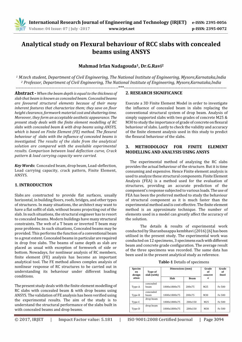
International Research Journal of Engineering and Technology (IRJET) e-ISSN: 2395-0056 Volume: 04 Issue: 07 | July -2017 www.irjet.net p-ISSN: 2395-0072 © 2017, IRJET | Impact Factor value: 5.181 | ISO 9001:2008 Certified Journal | Page 3094 Analytical study on Flexural behaviour of RCC slabs with concealed beams using ANSYS Mahmad Irfan Nadagouda 1 , Dr.G.Ravi 2 1 M.tech student, Department of Civil Engineering, The National Institute of Engineering, Mysore,Karnataka,India 2 Professor, Department of Civil Engineering, The National Institute of Engineering, Mysore,Karnataka,India ---------------------------------------------------------------------***--------------------------------------------------------------------- Abstract - When the beam depth is equal to the thickness of slab that beam is known as concealed beam. Concealed beams are favoured structural elements because of their many inherent features that characterize them; they save on floor height clearance, formwork material cost and shuttering time. Moreover, they form an acceptable aesthetic appearance. The present study deals with the finite element modelling of RC slabs with concealed beam & with drop beams using ANSYS, which is based on Finite Element (FE) method. The flexural behaviour of slabs with the influence of concealed beams is investigated. The results of the slabs from the analytical solution are compared with the available experimental results. Comparison between load deflection curve, Crack pattern & load carrying capacity were carried. Key Words: Concealed beam, drop beam, Load-deflection, Load carrying capacity, crack pattern, Finite Element, ANSYS. 1. INTRODUCTION Slabs are constructed to provide flat surfaces, usually horizontal, in building floors, roofs, bridges, and other types of structures. In many situations, the architect may want to have a flat soffit of slab, without beams projecting out of the slab. In such situations, the structural engineer has to resort to concealed beams. Modern buildings have many structural constraints. The web of a T beam or inverted T beam may pose problems. In such situations, Concealed beams may be provided. This performs the function of a conventional beam to a great extent. Concealed beams in particular are required in drop free slabs. The beams of same depth as slab are placed as usual with exception of formwork of side or bottom. Nowadays, for nonlinear analysis of RC members, finite element (FE) analysis has become an important analytical tool. The FE method allows complex analysis of nonlinear response of RC structures to be carried out in understanding its behaviour under different loading conditions. The present study deals with the finite element modelling of RC slabs with concealed beam & with drop beams using ANSYS. The validation of FE analysis has been verified using the experimental results. The aim of the study is to understand the structural performance of the slabs built in with concealed beams and drop beams. 2. RESEARCH SIGNIFICANCE Execute a 3D Finite Element Model in order to investigate the influence of concealed beam in slabs replacing the conventional structural system of drop beam. Analysis of simply supported slabs with two grades of concrete M25 & M30 to study the importance of grade of concrete on flexural behaviour of slabs. Lastly to check the validity and accuracy of the finite element analysis used in this study to predict the flexural behaviour of the slabs. 3. METHODOLOGY FOR FINITE ELEMENT MODELLING AND ANALYSIS USING ANSYS The experimental method of analyzing the RC slabs provides the actual behaviour of the structure. But it is time consuming and expensive. Hence Finite element analysis is used to analyze these structural components. Finite Element Analysis (FEA) is a method used for the evaluation of structures, providing an accurate prediction of the component’s response subjected to various loads. The use of FEA has been the preferred method to study the behaviour of structural component as it is much faster than the experimental method and is cost effective. The finite element method is an approximate technique. The number of elements used in a model can greatly affect the accuracy of the solution. The details & results of experimental work conducted by Sharanbasappa kembhavi (2016) [6] has been utilised in the present study. The experimental work was conducted on 12 specimens, 3 specimens each with different beam and concrete grade configuration. The average result of the three specimens was recorded. The same data has been used in the present analytical study as reference. Table-1 Details of specimens Specim en design ation Type of slab (with) Dimensions (mm) Grade of concret e Grade of Steel Slab Beam Type-A concealed beam 1000x1800x75 200x75 M25 Fe 500 Type-B concealed beam 1000x1800x75 200x75 M30 Fe 500 Type-C drop beam 1000x1800x75 200x150 M25 Fe 500 Type-D drop beam 1000x1800x75 200x150 M30 Fe 500
Transcript of Analytical study on Flexural behaviour of RCC … is capable of plastic deformation, cracking in...
International Research Journal of Engineering and Technology (IRJET) e-ISSN: 2395-0056
Volume: 04 Issue: 07 | July -2017 www.irjet.net p-ISSN: 2395-0072
© 2017, IRJET | Impact Factor value: 5.181 | ISO 9001:2008 Certified Journal | Page 3094
Analytical study on Flexural behaviour of RCC slabs with concealed beams using ANSYS
Mahmad Irfan Nadagouda1, Dr.G.Ravi2
1 M.tech student, Department of Civil Engineering, The National Institute of Engineering, Mysore,Karnataka,India 2 Professor, Department of Civil Engineering, The National Institute of Engineering, Mysore,Karnataka,India
---------------------------------------------------------------------***---------------------------------------------------------------------Abstract - When the beam depth is equal to the thickness of slab that beam is known as concealed beam. Concealed beams are favoured structural elements because of their many inherent features that characterize them; they save on floor height clearance, formwork material cost and shuttering time. Moreover, they form an acceptable aesthetic appearance. The present study deals with the finite element modelling of RC slabs with concealed beam & with drop beams using ANSYS, which is based on Finite Element (FE) method. The flexural behaviour of slabs with the influence of concealed beams is investigated. The results of the slabs from the analytical solution are compared with the available experimental results. Comparison between load deflection curve, Crack pattern & load carrying capacity were carried. Key Words: Concealed beam, drop beam, Load-deflection, Load carrying capacity, crack pattern, Finite Element, ANSYS.
1. INTRODUCTION Slabs are constructed to provide flat surfaces, usually horizontal, in building floors, roofs, bridges, and other types of structures. In many situations, the architect may want to have a flat soffit of slab, without beams projecting out of the slab. In such situations, the structural engineer has to resort to concealed beams. Modern buildings have many structural constraints. The web of a T beam or inverted T beam may pose problems. In such situations, Concealed beams may be provided. This performs the function of a conventional beam to a great extent. Concealed beams in particular are required in drop free slabs. The beams of same depth as slab are placed as usual with exception of formwork of side or bottom. Nowadays, for nonlinear analysis of RC members, finite element (FE) analysis has become an important analytical tool. The FE method allows complex analysis of nonlinear response of RC structures to be carried out in understanding its behaviour under different loading conditions. The present study deals with the finite element modelling of RC slabs with concealed beam & with drop beams using ANSYS. The validation of FE analysis has been verified using the experimental results. The aim of the study is to understand the structural performance of the slabs built in with concealed beams and drop beams.
2. RESEARCH SIGNIFICANCE Execute a 3D Finite Element Model in order to investigate the influence of concealed beam in slabs replacing the conventional structural system of drop beam. Analysis of simply supported slabs with two grades of concrete M25 & M30 to study the importance of grade of concrete on flexural behaviour of slabs. Lastly to check the validity and accuracy of the finite element analysis used in this study to predict the flexural behaviour of the slabs.
3. METHODOLOGY FOR FINITE ELEMENT MODELLING AND ANALYSIS USING ANSYS
The experimental method of analyzing the RC slabs provides the actual behaviour of the structure. But it is time consuming and expensive. Hence Finite element analysis is used to analyze these structural components. Finite Element Analysis (FEA) is a method used for the evaluation of structures, providing an accurate prediction of the component’s response subjected to various loads. The use of FEA has been the preferred method to study the behaviour of structural component as it is much faster than the experimental method and is cost effective. The finite element method is an approximate technique. The number of elements used in a model can greatly affect the accuracy of the solution.
The details & results of experimental work conducted by Sharanbasappa kembhavi (2016) [6] has been utilised in the present study. The experimental work was conducted on 12 specimens, 3 specimens each with different beam and concrete grade configuration. The average result of the three specimens was recorded. The same data has been used in the present analytical study as reference.
Table-1 Details of specimens
Specimen
designation
Type of
slab (with)
Dimensions (mm) Grade of
concrete
Grade of
Steel
Slab Beam
Type-A
concealed beam
1000x1800x75
200x75
M25
Fe 500
Type-B
concealed beam
1000x1800x75
200x75
M30
Fe 500
Type-C
drop beam 1000x1800x75
200x150
M25
Fe 500
Type-D
drop beam 1000x1800x75
200x150
M30
Fe 500
International Research Journal of Engineering and Technology (IRJET) e-ISSN: 2395-0056
Volume: 04 Issue: 07 | July -2017 www.irjet.net p-ISSN: 2395-0072
© 2017, IRJET | Impact Factor value: 5.181 | ISO 9001:2008 Certified Journal | Page 3095
(a) (b)
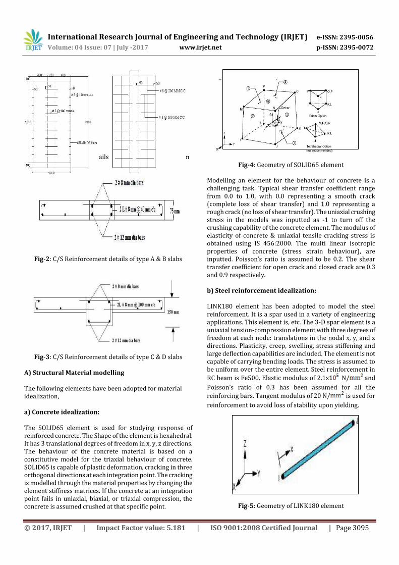
Fig-1: Reinforcement details of slabs at a) Top b) Bottom
Fig-2: C/S Reinforcement details of type A & B slabs
Fig-3: C/S Reinforcement details of type C & D slabs A) Structural Material modelling The following elements have been adopted for material idealization, a) Concrete idealization: The SOLID65 element is used for studying response of reinforced concrete. The Shape of the element is hexahedral. It has 3 translational degrees of freedom in x, y, z directions. The behaviour of the concrete material is based on a constitutive model for the triaxial behaviour of concrete. SOLID65 is capable of plastic deformation, cracking in three orthogonal directions at each integration point. The cracking is modelled through the material properties by changing the element stiffness matrices. If the concrete at an integration point fails in uniaxial, biaxial, or triaxial compression, the concrete is assumed crushed at that specific point.
Fig-4: Geometry of SOLID65 element
Modelling an element for the behaviour of concrete is a challenging task. Typical shear transfer coefficient range from 0.0 to 1.0, with 0.0 representing a smooth crack (complete loss of shear transfer) and 1.0 representing a rough crack (no loss of shear transfer). The uniaxial crushing stress in the models was inputted as -1 to turn off the crushing capability of the concrete element. The modulus of elasticity of concrete & uniaxial tensile cracking stress is obtained using IS 456:2000. The multi linear isotropic properties of concrete (stress strain behaviour), are inputted. Poisson’s ratio is assumed to be 0.2. The shear transfer coefficient for open crack and closed crack are 0.3 and 0.9 respectively. b) Steel reinforcement idealization: LINK180 element has been adopted to model the steel reinforcement. It is a spar used in a variety of engineering applications. This element is, etc. The 3-D spar element is a uniaxial tension-compression element with three degrees of freedom at each node: translations in the nodal x, y, and z directions. Plasticity, creep, swelling, stress stiffening and large deflection capabilities are included. The element is not capable of carrying bending loads. The stress is assumed to be uniform over the entire element. Steel reinforcement in
RC beam is Fe500. Elastic modulus of 2.1x N/ and
Poisson’s ratio of 0.3 has been assumed for all the
reinforcing bars. Tangent modulus of 20 N/ is used for
reinforcement to avoid loss of stability upon yielding.
Fig-5: Geometry of LINK180 element
International Research Journal of Engineering and Technology (IRJET) e-ISSN: 2395-0056
Volume: 04 Issue: 07 | July -2017 www.irjet.net p-ISSN: 2395-0072
© 2017, IRJET | Impact Factor value: 5.181 | ISO 9001:2008 Certified Journal | Page 3096
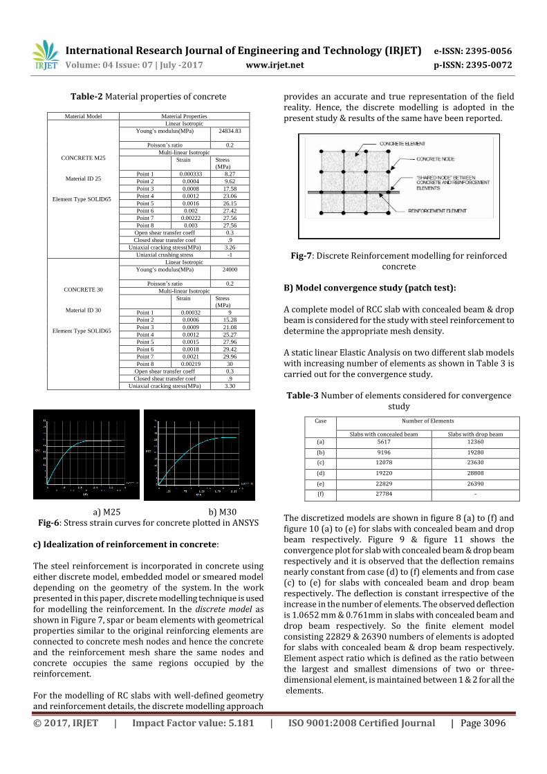
Table-2 Material properties of concrete
Material Model Material Properties
CONCRETE M25
Material ID 25
Element Type SOLID65
Linear Isotropic Young’s modulus(MPa) 24834.83
Poisson’s ratio 0.2
Multi-linear Isotropic Strain Stress
(MPa) Point 1 0.000333 8.27
Point 2 0.0004 9.62
Point 3 0.0008 17.58
Point 4 0.0012 23.06
Point 5 0.0016 26.15
Point 6 0.002 27.42
Point 7 0.00222 27.56
Point 8 0.003 27.56
Open shear transfer coeff 0.3
Closed shear transfer coef .9
Uniaxial cracking stress(MPa) 3.26
Uniaxial crushing stress -1
CONCRETE 30
Material ID 30
Element Type SOLID65
Linear Isotropic Young’s modulus(MPa) 24000
Poisson’s ratio 0.2
Multi-linear Isotropic Strain Stress
(MPa) Point 1 0.00032 9
Point 2 0.0006 15.28
Point 3 0.0009 21.08
Point 4 0.0012 25.27
Point 5 0.0015 27.96
Point 6 0.0018 29.42
Point 7 0.0021 29.96
Point 8 0.00219 30
Open shear transfer coeff 0.3
Closed shear transfer coef .9
Uniaxial cracking stress(MPa) 3.30
a) M25 b) M30 Fig-6: Stress strain curves for concrete plotted in ANSYS
c) Idealization of reinforcement in concrete: The steel reinforcement is incorporated in concrete using either discrete model, embedded model or smeared model depending on the geometry of the system. In the work presented in this paper, discrete modelling technique is used for modelling the reinforcement. In the discrete model as shown in Figure 7, spar or beam elements with geometrical properties similar to the original reinforcing elements are connected to concrete mesh nodes and hence the concrete and the reinforcement mesh share the same nodes and concrete occupies the same regions occupied by the reinforcement. For the modelling of RC slabs with well-defined geometry and reinforcement details, the discrete modelling approach
provides an accurate and true representation of the field reality. Hence, the discrete modelling is adopted in the present study & results of the same have been reported.
Fig-7: Discrete Reinforcement modelling for reinforced concrete
B) Model convergence study (patch test): A complete model of RCC slab with concealed beam & drop beam is considered for the study with steel reinforcement to determine the appropriate mesh density. A static linear Elastic Analysis on two different slab models with increasing number of elements as shown in Table 3 is carried out for the convergence study.
Table-3 Number of elements considered for convergence study
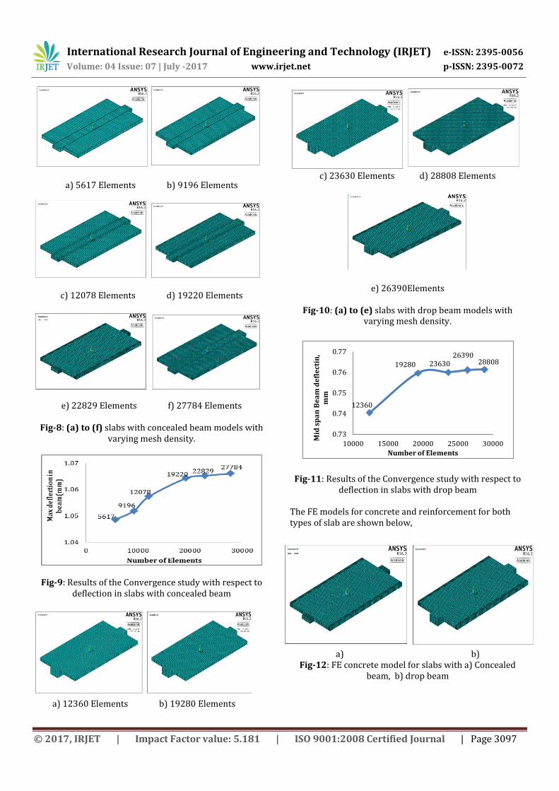
The discretized models are shown in figure 8 (a) to (f) and figure 10 (a) to (e) for slabs with concealed beam and drop beam respectively. Figure 9 & figure 11 shows the convergence plot for slab with concealed beam & drop beam respectively and it is observed that the deflection remains nearly constant from case (d) to (f) elements and from case (c) to (e) for slabs with concealed beam and drop beam respectively. The deflection is constant irrespective of the increase in the number of elements. The observed deflection is 1.0652 mm & 0.761mm in slabs with concealed beam and drop beam respectively. So the finite element model consisting 22829 & 26390 numbers of elements is adopted for slabs with concealed beam & drop beam respectively. Element aspect ratio which is defined as the ratio between the largest and smallest dimensions of two or three-dimensional element, is maintained between 1 & 2 for all the elements.
Case Number of Elements
Slabs with concealed beam Slabs with drop beam
(a) 5617 12360
(b) 9196 19280
(c) 12078 23630
(d) 19220 28808
(e) 22829 26390
(f) 27784 -
International Research Journal of Engineering and Technology (IRJET) e-ISSN: 2395-0056
Volume: 04 Issue: 07 | July -2017 www.irjet.net p-ISSN: 2395-0072
© 2017, IRJET | Impact Factor value: 5.181 | ISO 9001:2008 Certified Journal | Page 3097
a) 5617 Elements b) 9196 Elements
c) 12078 Elements d) 19220 Elements
e) 22829 Elements f) 27784 Elements
Fig-8: (a) to (f) slabs with concealed beam models with varying mesh density.
Fig-9: Results of the Convergence study with respect to deflection in slabs with concealed beam
a) 12360 Elements b) 19280 Elements
c) 23630 Elements d) 28808 Elements
e) 26390Elements
Fig-10: (a) to (e) slabs with drop beam models with varying mesh density.
12360
19280 2363026390
28808
0.73
0.74
0.75
0.76
0.77
10000 15000 20000 25000 30000
Mid
sp
an
Be
am
de
fle
ctin
, m
m
Number of Elements
Fig-11: Results of the Convergence study with respect to
deflection in slabs with drop beam
The FE models for concrete and reinforcement for both types of slab are shown below,
a) b) Fig-12: FE concrete model for slabs with a) Concealed
beam, b) drop beam
International Research Journal of Engineering and Technology (IRJET) e-ISSN: 2395-0056
Volume: 04 Issue: 07 | July -2017 www.irjet.net p-ISSN: 2395-0072
© 2017, IRJET | Impact Factor value: 5.181 | ISO 9001:2008 Certified Journal | Page 3098
(a) (b)
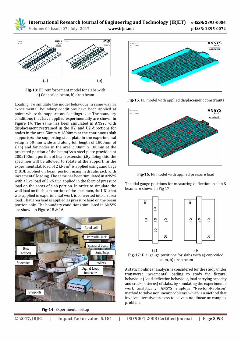
Fig-13: FE reinforcement model for slabs with a) Concealed beam, b) drop beam
Loading: To simulate the model behaviour in same way as experimental, boundary conditions have been applied at points where the supports and loadings exist. The boundary conditions that have applied experimentally are shown in Figure 14. The same has been simulated in ANSYS with displacement restrained in the UY, and UZ directions for nodes in the area 50mm x 1800mm at the continuous slab support(As the supporting steel plate in the experimental setup is 50 mm wide and along full length of 1800mm of slab) and for nodes in the area 200mm x 100mm at the projected portion of the beam(As a steel plate provided at 200x100mm portion of beam extension).By doing this, the specimen will be allowed to rotate at the support. In the experiment slab load 0f 2 kN/ is applied using sand bags & UDL applied on beam portion using hydraulic jack with incremental loading. The same has been simulated in ANSYS
with a live load of 2 kN/ applied in the form of pressure load on the areas of slab portion. In order to simulate the wall load on the beam portion of the specimen, the UDL that was applied in experimental work is converted into an area load. That area load is applied as pressure load on the beam portion only. The boundary conditions simulated in ANSYS are shown in Figure 15 & 16.
Fig-14: Experimental setup
Fig-15: FE model with applied displacement constraints
Fig-16: FE model with applied pressure load
The dial gauge positions for measuring deflection in slab & beam are shown in Fig 17
(a) (b) Fig-17: Dial gauge positions for slabs with a) concealed
beam, b) drop beam A static nonlinear analysis is considered for the study under transverse incremental loading to study the flexural behaviour (Load deflection behaviour, load carrying capacity and crack patterns) of slabs, by simulating the experimental work analytically. ANSYS employs “Newton-Raphson” method to solve nonlinear problems, which is a method that involves iterative process to solve a nonlinear or complex problem.
International Research Journal of Engineering and Technology (IRJET) e-ISSN: 2395-0056
Volume: 04 Issue: 07 | July -2017 www.irjet.net p-ISSN: 2395-0072
© 2017, IRJET | Impact Factor value: 5.181 | ISO 9001:2008 Certified Journal | Page 3099
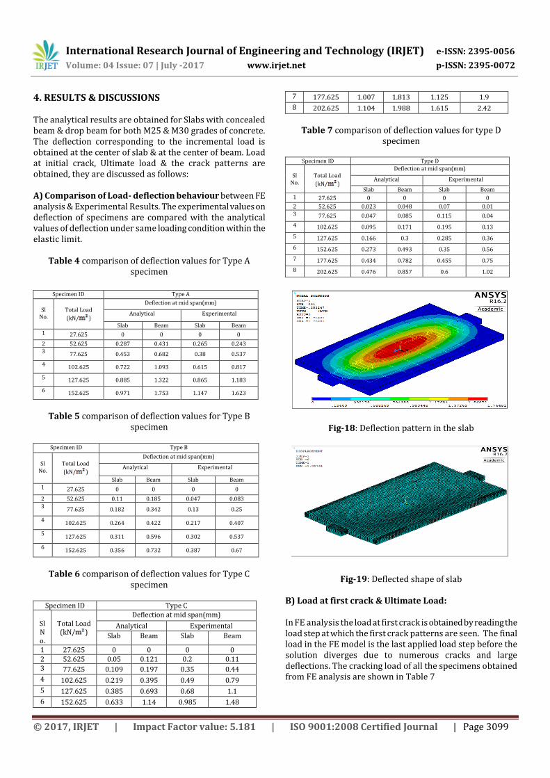
4. RESULTS & DISCUSSIONS The analytical results are obtained for Slabs with concealed beam & drop beam for both M25 & M30 grades of concrete. The deflection corresponding to the incremental load is obtained at the center of slab & at the center of beam. Load at initial crack, Ultimate load & the crack patterns are obtained, they are discussed as follows: A) Comparison of Load- deflection behaviour between FE analysis & Experimental Results. The experimental values on deflection of specimens are compared with the analytical values of deflection under same loading condition within the elastic limit.
Table 4 comparison of deflection values for Type A specimen
Table 5 comparison of deflection values for Type B specimen
Table 6 comparison of deflection values for Type C
specimen
Specimen ID Type C
Sl No.
Total Load (kN/ )
Deflection at mid span(mm)
Analytical Experimental
Slab Beam Slab Beam
1 27.625 0 0 0 0 2 52.625 0.05 0.121 0.2 0.11 3 77.625 0.109 0.197 0.35 0.44
4 102.625 0.219 0.395 0.49 0.79
5 127.625 0.385 0.693 0.68 1.1
6 152.625 0.633 1.14 0.985 1.48
7 177.625 1.007 1.813 1.125 1.9
8 202.625 1.104 1.988 1.615 2.42
Table 7 comparison of deflection values for type D specimen
Specimen ID Type D
Sl
No.
Total Load
(kN/ )
Deflection at mid span(mm)
Analytical Experimental
Slab Beam Slab Beam
1 27.625 0 0 0 0
2 52.625 0.023 0.048 0.07 0.01 3 77.625 0.047 0.085 0.115 0.04
4 102.625 0.095 0.171 0.195 0.13
5 127.625 0.166 0.3 0.285 0.36
6 152.625 0.273 0.493 0.35 0.56
7 177.625 0.434 0.782 0.455 0.75
8 202.625 0.476 0.857 0.6 1.02
Fig-18: Deflection pattern in the slab
Fig-19: Deflected shape of slab B) Load at first crack & Ultimate Load: In FE analysis the load at first crack is obtained by reading the load step at which the first crack patterns are seen. The final load in the FE model is the last applied load step before the solution diverges due to numerous cracks and large deflections. The cracking load of all the specimens obtained from FE analysis are shown in Table 7
Specimen ID Type A
Sl
No.
Total Load
(kN/ )
Deflection at mid span(mm)
Analytical Experimental
Slab Beam Slab Beam
1 27.625 0 0 0 0
2 52.625 0.287 0.431 0.265 0.243
3 77.625 0.453 0.682 0.38 0.537
4 102.625 0.722 1.093 0.615 0.817
5 127.625 0.885 1.322 0.865 1.183
6 152.625 0.971 1.753 1.147 1.623
Specimen ID Type B
Sl
No.
Total Load
(kN/ )
Deflection at mid span(mm)
Analytical Experimental
Slab Beam Slab Beam
1 27.625 0 0 0 0
2 52.625 0.11 0.185 0.047 0.083
3 77.625 0.182 0.342 0.13 0.25
4 102.625 0.264 0.422 0.217 0.407
5 127.625 0.311 0.596 0.302 0.537
6 152.625 0.356 0.732 0.387 0.67
International Research Journal of Engineering and Technology (IRJET) e-ISSN: 2395-0056
Volume: 04 Issue: 07 | July -2017 www.irjet.net p-ISSN: 2395-0072
© 2017, IRJET | Impact Factor value: 5.181 | ISO 9001:2008 Certified Journal | Page 3100
Table 7 Comparison of Analytical loads with experimental Loads
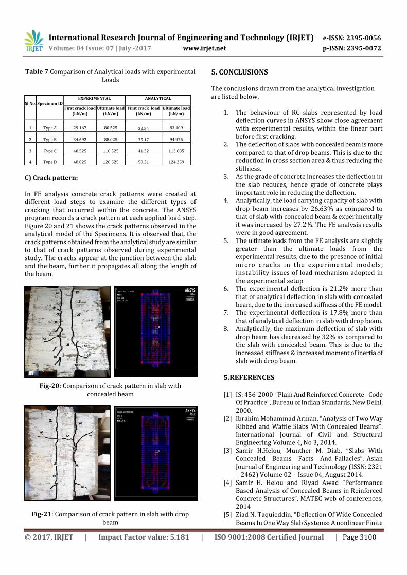
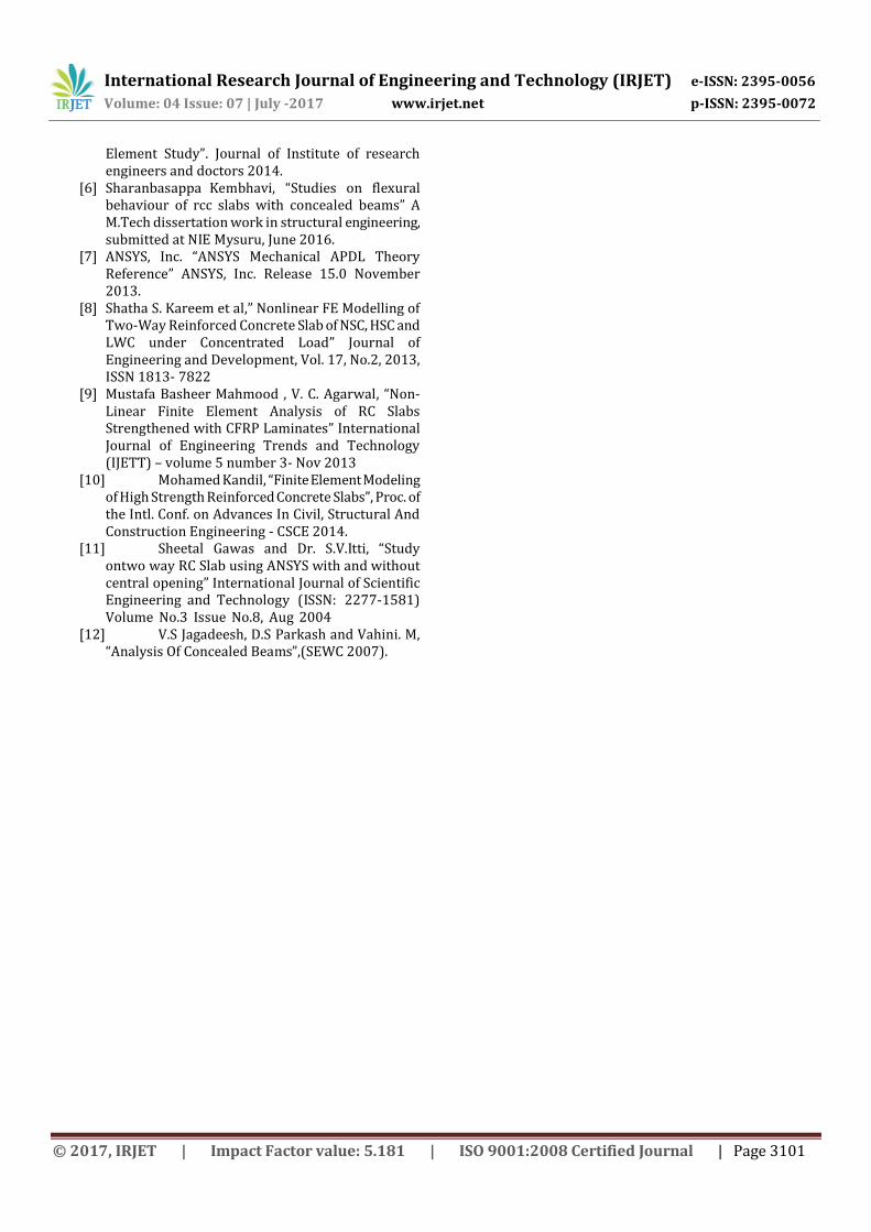
C) Crack pattern: In FE analysis concrete crack patterns were created at different load steps to examine the different types of cracking that occurred within the concrete. The ANSYS program records a crack pattern at each applied load step. Figure 20 and 21 shows the crack patterns observed in the analytical model of the Specimens. It is observed that, the crack patterns obtained from the analytical study are similar to that of crack patterns observed during experimental study. The cracks appear at the junction between the slab and the beam, further it propagates all along the length of the beam.
Fig-20: Comparison of crack pattern in slab with concealed beam
Fig-21: Comparison of crack pattern in slab with drop beam
5. CONCLUSIONS The conclusions drawn from the analytical investigation are listed below,
1. The behaviour of RC slabs represented by load deflection curves in ANSYS show close agreement with experimental results, within the linear part before first cracking.
2. The deflection of slabs with concealed beam is more compared to that of drop beams. This is due to the reduction in cross section area & thus reducing the stiffness.
3. As the grade of concrete increases the deflection in the slab reduces, hence grade of concrete plays important role in reducing the deflection.
4. Analytically, the load carrying capacity of slab with drop beam increases by 26.63% as compared to that of slab with concealed beam & experimentally it was increased by 27.2%. The FE analysis results were in good agreement.
5. The ultimate loads from the FE analysis are slightly greater than the ultimate loads from the experimental results, due to the presence of initial micro cracks in the experimental models , instability issues of load mechanism adopted in the experimental setup
6. The experimental deflection is 21.2% more than that of analytical deflection in slab with concealed beam, due to the increased stiffness of the FE model.
7. The experimental deflection is 17.8% more than that of analytical deflection in slab with drop beam.
8. Analytically, the maximum deflection of slab with drop beam has decreased by 32% as compared to the slab with concealed beam. This is due to the increased stiffness & increased moment of inertia of slab with drop beam.
5.REFERENCES [1] IS: 456-2000 “Plain And Reinforced Concrete - Code
Of Practice”, Bureau of Indian Standards, New Delhi, 2000.
[2] Ibrahim Mohammad Arman, “Analysis of Two Way Ribbed and Waffle Slabs With Concealed Beams”. International Journal of Civil and Structural Engineering Volume 4, No 3, 2014.
[3] Samir H.Helou, Munther M. Diab, “Slabs With Concealed Beams Facts And Fallacies”. Asian Journal of Engineering and Technology (ISSN: 2321 – 2462) Volume 02 – Issue 04, August 2014.
[4] Samir H. Helou and Riyad Awad “Performance Based Analysis of Concealed Beams in Reinforced Concrete Structures”. MATEC web of conferences, 2014
[5] Ziad N. Taquieddin, “Deflection Of Wide Concealed Beams In One Way Slab Systems: A nonlinear Finite
Sl No.
Specimen ID
EXPERIMENTAL ANALYTICAL
First crack load (kN/m)
Ultimate load (kN/m)
First crack load (kN/m)
Ultimate load (kN/m)
1
Type A
29.167
80.525 32.54
83.409
2
Type B
34.692
88.025 35.17
94.976
3
Type C
40.525
110.525
41.32
113.685
4
Type D
48.025
120.525
50.21
124.259
International Research Journal of Engineering and Technology (IRJET) e-ISSN: 2395-0056
Volume: 04 Issue: 07 | July -2017 www.irjet.net p-ISSN: 2395-0072
© 2017, IRJET | Impact Factor value: 5.181 | ISO 9001:2008 Certified Journal | Page 3101
Element Study”. Journal of Institute of research engineers and doctors 2014.
[6] Sharanbasappa Kembhavi, “Studies on flexural behaviour of rcc slabs with concealed beams” A M.Tech dissertation work in structural engineering, submitted at NIE Mysuru, June 2016.
[7] ANSYS, Inc. “ANSYS Mechanical APDL Theory Reference” ANSYS, Inc. Release 15.0 November 2013.
[8] Shatha S. Kareem et al,” Nonlinear FE Modelling of Two-Way Reinforced Concrete Slab of NSC, HSC and LWC under Concentrated Load” Journal of Engineering and Development, Vol. 17, No.2, 2013, ISSN 1813‐ 7822
[9] Mustafa Basheer Mahmood , V. C. Agarwal, “Non-Linear Finite Element Analysis of RC Slabs Strengthened with CFRP Laminates” International Journal of Engineering Trends and Technology (IJETT) – volume 5 number 3- Nov 2013
[10] Mohamed Kandil, “Finite Element Modeling of High Strength Reinforced Concrete Slabs”, Proc. of the Intl. Conf. on Advances In Civil, Structural And Construction Engineering - CSCE 2014.
[11] Sheetal Gawas and Dr. S.V.Itti, “Study ontwo way RC Slab using ANSYS with and without central opening” International Journal of Scientific Engineering and Technology (ISSN: 2277-1581) Volume No.3 Issue No.8, Aug 2004
[12] V.S Jagadeesh, D.S Parkash and Vahini. M, “Analysis Of Concealed Beams”,(SEWC 2007).