Analytical and Modeling Study of Composite Material … in order to obtain the reduction of the...
15
IOSR Journal of Mechanical and Civil Engineering (IOSR-JMCE) e-ISSN: 2278-1684,p-ISSN: 2320-334X, Volume 13, Issue 2 Ver. IV (Mar- Apr. 2016), PP 34-48 www.iosrjournals.org DOI: 10.9790/1684-1302043448 www.iosrjournals.org 34 | Page Analytical and Modeling Study of Composite Material Drive Shaft for an Automobile Ketan S. Patil a , Dr. A. J. Keche b , Prof. V. M. Chidri c a: PG Student, Department of Mechanical Engineering Maharashtra institute of technology, Aurangabad, India b: Associate Professor, Department of Mechanical Engineering Maharashtra Institute of Technology, Aurangabad, India c: Associate Professor, Department of Mechanical Engineering Maharashtra Institute of Technology, Aurangabad, India Abstract: The advanced composite materials such as Graphite, Carbon, Kevlar and Glass with suitable resins are widely used because of their high specific strength (strength/density) and high specific modulus (modulus/density). The weight reduction of the drive shaft can have a certain role in the general weight reduction of the vehicle and is a highly desirable goal, if it can be achieved without increase in cost and decrease in quality and reliability. It is possible to achieve design of composite drive shaft with less weight to increase the natural frequency of the shaft, decrease the bending stresses, and maximize the torque transmission and torsional buckling capabilities. Substituting composite material structure for conventional metallic structure has many advantages because of high specific strength and stiffness of composite material. This work deals with the replacement of conventional two-piece drive shaft with a single piece E-glass/Epoxy, high strength carbon/ epoxy, high modulus carbon/ epoxy composite drive shaft for an automotive application. The design parameters were optimized with the objective of minimizing the weight of composite drive shaft. The design optimization also showed significant potential improvement in the performance of drive shaft. Key words: Bernoulli Euler theory, Static Analysis, Modal analysis, Buckling analysis, ANSYS I. Introduction The advanced composite materials such as Graphite, Carbon, Kevlar and Glass with suitable resins are widely used because of their high specific strength (strength/density) and high specific modulus (modulus/density). Advanced composite materials seem ideally suited for long, power driver shaft (propeller shaft) applications. Their elastic properties can be tailored to increase the torque they can carry as well as the rotational speed at which they operate. The drive shafts are used in automotive, aircraft and aerospace applications. The automotive industry is exploiting composite material technology for structural components construction in order to obtain the reduction of the weight without decrease in vehicle quality and reliability. It is known that energy conservation is one of the most important objectives in vehicle design and reduction of weight is one of the most effective measures to obtain this result. Actually, there is almost a direct proportionality between the weight of a vehicle and its fuel consumption, particularly in city driving. Deborah D.L. Chung (2015) gives carbon fiber composites in depth review. Carbon fibers refer to fibers which are at least 92 wt. % carbons in composition. They can be short or continuous; their structure can be crystalline, amorphous, or partly crystalline. G.J. Withers et al. (2015) modified surface nanoclay reinforced epoxy glass-fiber composite is evaluated for properties of mechanical strength, stiffness, ductility and fatigue life, and compared with the pristine or epoxy glass-fiber composite material not reinforced with nanoclays Daniel Lawrence et al. (2014) examine the result of fiber orientation angles and stacking sequence on the torsional stiffness, natural frequency and buckling strength of composite drive shaft. The weight reduction of the drive shaft can have a certain role in the general weight reduction of the vehicle and is a highly desirable goal Ravi Arun (2014) worked for weight reduction of the drive shaft which have a certain role in the general weight reduction of the vehicle and is a highly desirable goal, if it can be achieved without increase in cost and decrease in quality and reliability. It is possible to achieve design of composite drive shaft with less weight to increase the first natural frequency of the shaft and to decrease the bending stresses using various stacking sequences. S V Gopals Krishna et al. (2013) examine that almost all automobiles (at least those which correspond to design with rear wheel drive and front engine installation) have transmission shafts. The weight reduction of the drive shaft can have a certain role in the general weight reduction of the vehicle and is a highly desirable goal. Substituting composite structures for conventional metallic structures has many advantages because of higher specific stiffness and strength of composite materials.
Transcript of Analytical and Modeling Study of Composite Material … in order to obtain the reduction of the...

IOSR Journal of Mechanical and Civil Engineering (IOSR-JMCE)
e-ISSN: 2278-1684,p-ISSN: 2320-334X, Volume 13, Issue 2 Ver. IV (Mar- Apr. 2016), PP 34-48
www.iosrjournals.org
DOI: 10.9790/1684-1302043448 www.iosrjournals.org 34 | Page
Analytical and Modeling Study of Composite Material Drive
Shaft for an Automobile
Ketan S. Patila, Dr. A. J. Keche
b, Prof. V. M. Chidri
c
a: PG Student, Department of Mechanical Engineering Maharashtra institute of technology, Aurangabad, India
b: Associate Professor, Department of Mechanical Engineering Maharashtra Institute of Technology,
Aurangabad, India
c: Associate Professor, Department of Mechanical Engineering Maharashtra Institute of Technology,
Aurangabad, India
Abstract: The advanced composite materials such as Graphite, Carbon, Kevlar and Glass with suitable resins
are widely used because of their high specific strength (strength/density) and high specific modulus
(modulus/density). The weight reduction of the drive shaft can have a certain role in the general weight
reduction of the vehicle and is a highly desirable goal, if it can be achieved without increase in cost and
decrease in quality and reliability. It is possible to achieve design of composite drive shaft with less weight to
increase the natural frequency of the shaft, decrease the bending stresses, and maximize the torque transmission
and torsional buckling capabilities. Substituting composite material structure for conventional metallic
structure has many advantages because of high specific strength and stiffness of composite material. This work
deals with the replacement of conventional two-piece drive shaft with a single piece E-glass/Epoxy, high
strength carbon/ epoxy, high modulus carbon/ epoxy composite drive shaft for an automotive application. The
design parameters were optimized with the objective of minimizing the weight of composite drive shaft. The
design optimization also showed significant potential improvement in the performance of drive shaft.
Key words: Bernoulli Euler theory, Static Analysis, Modal analysis, Buckling analysis, ANSYS
I. Introduction
The advanced composite materials such as Graphite, Carbon, Kevlar and Glass with suitable resins are
widely used because of their high specific strength (strength/density) and high specific modulus
(modulus/density). Advanced composite materials seem ideally suited for long, power driver shaft (propeller
shaft) applications. Their elastic properties can be tailored to increase the torque they can carry as well as the
rotational speed at which they operate. The drive shafts are used in automotive, aircraft and aerospace
applications. The automotive industry is exploiting composite material technology for structural components
construction in order to obtain the reduction of the weight without decrease in vehicle quality and reliability. It
is known that energy conservation is one of the most important objectives in vehicle design and reduction of
weight is one of the most effective measures to obtain this result. Actually, there is almost a direct
proportionality between the weight of a vehicle and its fuel consumption, particularly in city driving.
Deborah D.L. Chung (2015) gives carbon fiber composites in depth review. Carbon fibers refer to
fibers which are at least 92 wt. % carbons in composition. They can be short or continuous; their structure can
be crystalline, amorphous, or partly crystalline.
G.J. Withers et al. (2015) modified surface nanoclay reinforced epoxy glass-fiber composite is
evaluated for properties of mechanical strength, stiffness, ductility and fatigue life, and compared with the
pristine or epoxy glass-fiber composite material not reinforced with nanoclays
Daniel Lawrence et al. (2014) examine the result of fiber orientation angles and stacking sequence on
the torsional stiffness, natural frequency and buckling strength of composite drive shaft. The weight reduction of
the drive shaft can have a certain role in the general weight reduction of the vehicle and is a highly desirable
goal
Ravi Arun (2014) worked for weight reduction of the drive shaft which have a certain role in the
general weight reduction of the vehicle and is a highly desirable goal, if it can be achieved without increase in
cost and decrease in quality and reliability. It is possible to achieve design of composite drive shaft with less
weight to increase the first natural frequency of the shaft and to decrease the bending stresses using various
stacking sequences.
S V Gopals Krishna et al. (2013) examine that almost all automobiles (at least those which correspond
to design with rear wheel drive and front engine installation) have transmission shafts. The weight reduction of
the drive shaft can have a certain role in the general weight reduction of the vehicle and is a highly desirable
goal. Substituting composite structures for conventional metallic structures has many advantages because of
higher specific stiffness and strength of composite materials.

Analytical and Modeling Study of Composite Material Drive Shaft for an Automobile
DOI: 10.9790/1684-1302043448 www.iosrjournals.org 35 | Page
1.1 Purpose of the Drive Shaft The torque that is produced from the engine and transmission must be transferred to the rear wheels to
push the vehicle forward and reverse. The drive shaft must provide a smooth, uninterrupted flow of power to the
axles. The drive shaft and differential are used to transfer this torque.
1.2 Functions of the Drive Shaft
1. First, it must transmit torque from the transmission to the differential gear box.
2. During the operation, it is necessary to transmit maximum low-gear torque developed by the engine.
3. The drive shafts must also be capable of rotating at the very fast speeds required by the vehicle.
4. The drive shaft must also operate through constantly changing angles between the transmission, the
differential and the axles. As the rear wheels roll over bumps in the road, the differential and axles move up
and down. This movement changes the angle between the transmission and the differential.
5. The length of the drive shaft must also be capable of changing while transmitting torque. Length changes
are caused by axle movement due to torque reaction, road deflections, braking loads and so on. A slip joint
is used to compensate for this motion. The slip joint is usually made of an internal and external spline. It is
located on the front end of the drive shaft and is connected to the transmission.
1.3 Drive Shaft Arrangement in a Car Model Conventional two-piece drive shaft arrangement for rear wheel vehicle driving system is shown in fig.
1 below.
Fig.1 Conventional two-piece drive shaft arrangements for rear wheel vehicle driving system
1.4 Parts of Drive Shaft and Universal Joint
Parts of drive shaft and universal joint are shown in fig. 2 below;
Fig. 2 Parts of drive shaft and universal joint.
1.U-bolt nut 2. U-bolt washers 3. U-bolt
4.Universal joint journal 5.Lubrication fitting 6. Snap ring
7.Universal joint sleeve yoke 8. Spline seal 9. Dust cap
10.Drive shaft tube
1.5 Material of Conventional Steel Drive Shaft
Steel (SM45C) used for automotive drive shaft applications. The material properties of the steel
(SM45C) are given in Table 1
Analytical and Modeling Study of Composite Material Drive Shaft for an Automobile
DOI: 10.9790/1684-1302043448 www.iosrjournals.org 36 | Page
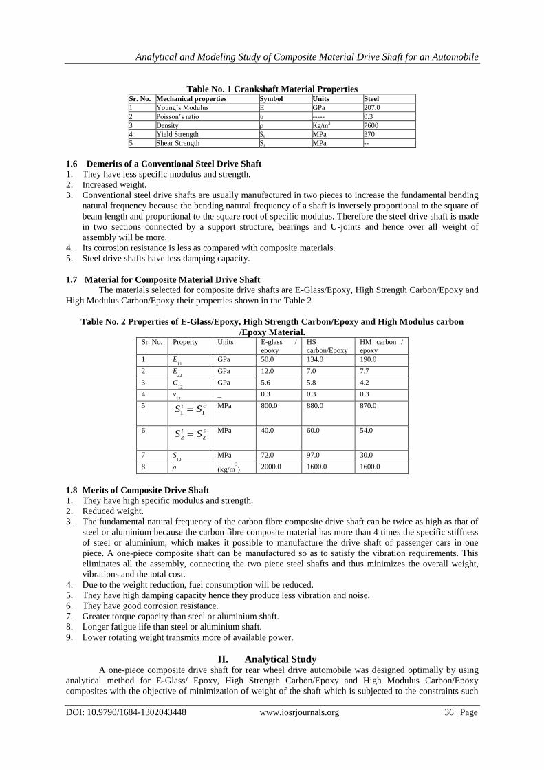
Table No. 1 Crankshaft Material Properties Sr. No. Mechanical properties Symbol Units Steel
1 Young’s Modulus E GPa 207.0
2 Poisson’s ratio υ ----- 0.3
3 Density ρ Kg/m3 7600
4 Yield Strength Sy MPa 370
5 Shear Strength Ss MPa --
1.6 Demerits of a Conventional Steel Drive Shaft 1. They have less specific modulus and strength.
2. Increased weight.
3. Conventional steel drive shafts are usually manufactured in two pieces to increase the fundamental bending
natural frequency because the bending natural frequency of a shaft is inversely proportional to the square of
beam length and proportional to the square root of specific modulus. Therefore the steel drive shaft is made
in two sections connected by a support structure, bearings and U-joints and hence over all weight of
assembly will be more.
4. Its corrosion resistance is less as compared with composite materials.
5. Steel drive shafts have less damping capacity.
1.7 Material for Composite Material Drive Shaft
The materials selected for composite drive shafts are E-Glass/Epoxy, High Strength Carbon/Epoxy and
High Modulus Carbon/Epoxy their properties shown in the Table 2
Table No. 2 Properties of E-Glass/Epoxy, High Strength Carbon/Epoxy and High Modulus carbon
/Epoxy Material. Sr. No. Property Units E-glass /
epoxy
HS
carbon/Epoxy
HM carbon /
epoxy
1 E11
GPa 50.0 134.0 190.0
2 E22
GPa 12.0 7.0 7.7
3 G12
GPa 5.6 5.8 4.2
4 ν12
_ 0.3 0.3 0.3
5 1 1
t cS S
MPa 800.0 880.0 870.0
6 2 2
t cS S
MPa 40.0 60.0 54.0
7 S12
MPa 72.0 97.0 30.0
8 ρ (kg/m3
) 2000.0 1600.0 1600.0
1.8 Merits of Composite Drive Shaft 1. They have high specific modulus and strength.
2. Reduced weight.
3. The fundamental natural frequency of the carbon fibre composite drive shaft can be twice as high as that of
steel or aluminium because the carbon fibre composite material has more than 4 times the specific stiffness
of steel or aluminium, which makes it possible to manufacture the drive shaft of passenger cars in one
piece. A one-piece composite shaft can be manufactured so as to satisfy the vibration requirements. This
eliminates all the assembly, connecting the two piece steel shafts and thus minimizes the overall weight,
vibrations and the total cost.
4. Due to the weight reduction, fuel consumption will be reduced.
5. They have high damping capacity hence they produce less vibration and noise.
6. They have good corrosion resistance.
7. Greater torque capacity than steel or aluminium shaft.
8. Longer fatigue life than steel or aluminium shaft.
9. Lower rotating weight transmits more of available power.
II. Analytical Study A one-piece composite drive shaft for rear wheel drive automobile was designed optimally by using
analytical method for E-Glass/ Epoxy, High Strength Carbon/Epoxy and High Modulus Carbon/Epoxy
composites with the objective of minimization of weight of the shaft which is subjected to the constraints such
Analytical and Modeling Study of Composite Material Drive Shaft for an Automobile
DOI: 10.9790/1684-1302043448 www.iosrjournals.org 37 | Page
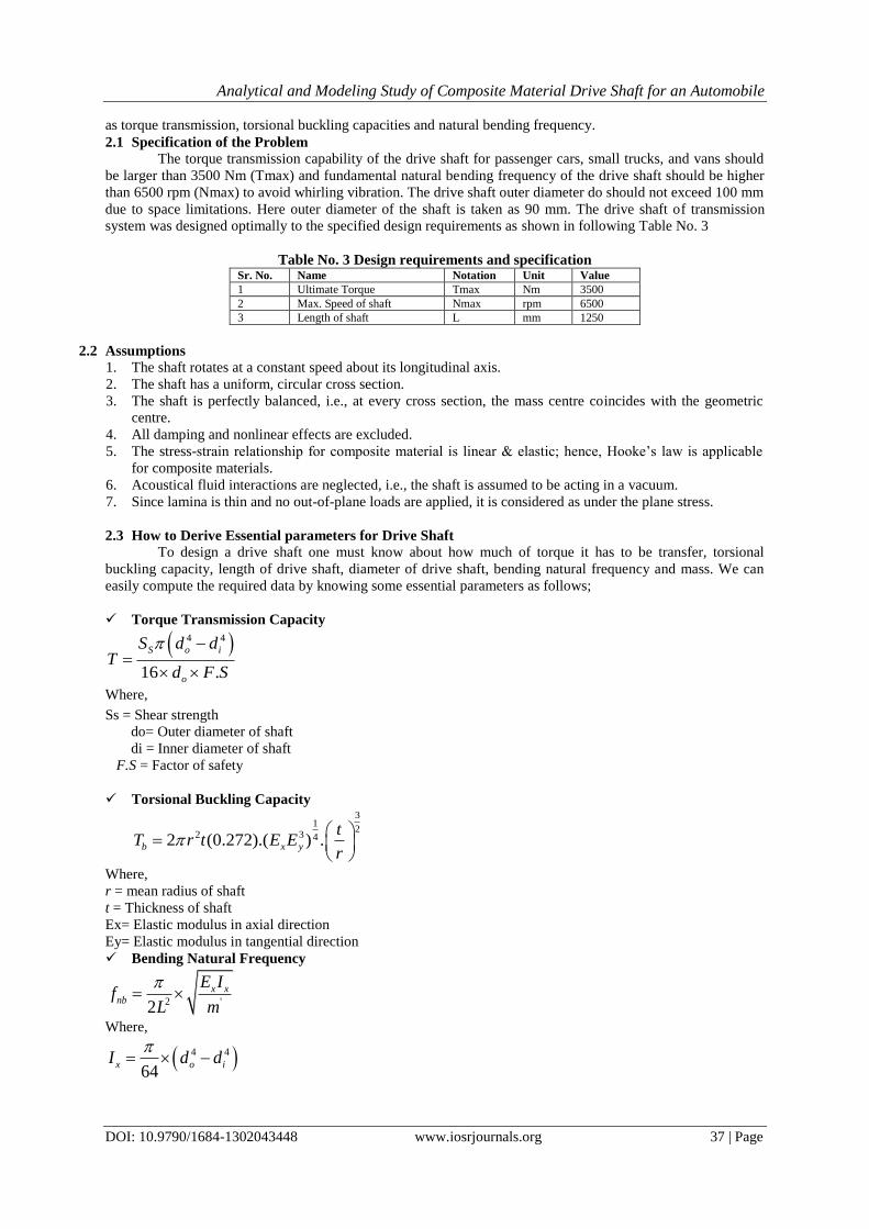
as torque transmission, torsional buckling capacities and natural bending frequency.
2.1 Specification of the Problem
The torque transmission capability of the drive shaft for passenger cars, small trucks, and vans should
be larger than 3500 Nm (Tmax) and fundamental natural bending frequency of the drive shaft should be higher
than 6500 rpm (Nmax) to avoid whirling vibration. The drive shaft outer diameter do should not exceed 100 mm
due to space limitations. Here outer diameter of the shaft is taken as 90 mm. The drive shaft of transmission
system was designed optimally to the specified design requirements as shown in following Table No. 3
Table No. 3 Design requirements and specification Sr. No. Name Notation Unit Value
1 Ultimate Torque Tmax Nm 3500
2 Max. Speed of shaft Nmax rpm 6500
3 Length of shaft L mm 1250
2.2 Assumptions
1. The shaft rotates at a constant speed about its longitudinal axis.
2. The shaft has a uniform, circular cross section.
3. The shaft is perfectly balanced, i.e., at every cross section, the mass centre coincides with the geometric
centre.
4. All damping and nonlinear effects are excluded.
5. The stress-strain relationship for composite material is linear & elastic; hence, Hooke’s law is applicable
for composite materials.
6. Acoustical fluid interactions are neglected, i.e., the shaft is assumed to be acting in a vacuum.
7. Since lamina is thin and no out-of-plane loads are applied, it is considered as under the plane stress.
2.3 How to Derive Essential parameters for Drive Shaft
To design a drive shaft one must know about how much of torque it has to be transfer, torsional
buckling capacity, length of drive shaft, diameter of drive shaft, bending natural frequency and mass. We can
easily compute the required data by knowing some essential parameters as follows;
Torque Transmission Capacity
4 4
16 .
S o i
o
S d dT
d F S
Where,
Ss = Shear strength
do= Outer diameter of shaft
di = Inner diameter of shaft
F.S = Factor of safety
Torsional Buckling Capacity 3
12
2 3 42 (0.272).( ) .b x y
tT r t E E
r
Where,
r = mean radius of shaft
t = Thickness of shaft
Ex= Elastic modulus in axial direction
Ey= Elastic modulus in tangential direction
Bending Natural Frequency
2 '2
x xnb
E If
L m
Where,
4 4
64x o iI d d

Analytical and Modeling Study of Composite Material Drive Shaft for an Automobile
DOI: 10.9790/1684-1302043448 www.iosrjournals.org 38 | Page
' 2 2
4o im d d
Where,
fnb = Natural frequency
L = Length of shaft
Ix= Moment of inertia of cross section of shaft
m’= Mass of shaft per unit length
Mass 'm m L
Percentage of Reduction in Mass
1 100new
old
m
m
Design Constraints
Torque transmission capacity of the shaft T ≥Tmax
Buckling torque capacity of the shaft Tcr ≥Tmax
Lateral fundamental natural frequency N ≥Ncrt
2.3 Calculations for Steel drive shaft
a) Torque transmission capacity of Steel Drive Shaft
4 4
16 .
S o i
o
S d dT
d F S
4 4
0 id d = (T x 16 x do x F.S.)/Ss X π
= (3500 x 16 x 0.09 x4)/ (370x 106 x π)
4 4
0 id d = 1.734 x 10
-5
4
id
= 4
od -1.734 x 10⁻⁵
id = 0.0833510m
id = 83.35
ir = 41.675mm
Hence, thickness of shaft
0 it r r
t = 45 - 41.6755 (2
i or rr
; r = 43.337mm)
t = 3.324mm
t = 3.324 x 10⁻³
m.
b) Torsional Buckling Capacity of Steel Drive Shaft (it must satisfy the following condition) 2
32
15.5,
(2 )1
L t
rv
It is for long shaft only.
As it satisfy the condition the next step is to calculate the torsional buckling Capacity
So,
[1/√(1-0.32)] x [(1250 x 10
-3)
2 x 3.324 x10
-3 ]/ 2x 43.3377 > 5.5
= 8.3612 > 5.5
Condition satisfied.
Now, Torsional Buckling Capacity 22cr crT r t
and
Analytical and Modeling Study of Composite Material Drive Shaft for an Automobile
DOI: 10.9790/1684-1302043448 www.iosrjournals.org 39 | Page
3/2
2 3/4( / )
3 2(1 )cr
Et r
v
cr = 1.112361 x 10⁹ N/m
2
and
bT = cr (2πr2t)
bT = 3733.44 Nm
Thus bT > T
c) Bending Natural Frequency of Steel Drive Shaft According to Bernoulli- Euler beam theory
The Bending natural Frequency of rotating shaft is given by. 2
12/
2nbe x
pf EI m
L
Where,
p – No of frequency (1st, 2
nd, 3
rd ….)
Ix = π/64 (do4-di
4)
&
m’=ρ (π/4) 2 2
o id d
Hence,
Ix = 8.5147 x 10⁻⁷
m4
And
m’= 6.881kg/m
nbf = 160.89 Hz
d) Mass of Steel Drive Shaft M = m
’ x L
= 6.881 x 1.25
= 8.601 kg.
2.4 Calculations for E-Glass / Epoxy Drive Shaft
a) Torque Transmission capacity of E-Glass/Epoxy Drive Shaft
4 4
16 .
S o i
o
S d dT
d F S
4 4
o id d = (T x 16 x d o x F.S.) / Ss x π
Hence id = 0.0764467 m
id = 76.44 mm
& ir =38.22 mm
o it r r
Hence t = 6.77 mm
& 0
2
ir rr
r = 41.61mm
b) Torsional Buckling Capacity of E-Glass/Epoxy Drive Shaft
Buckling Torque is given by,
2 3 0.25 1.5(2 r t)(0.272)(E E ) ( / )cr x yT t r
bT = 3893.86 Nm
As,
Analytical and Modeling Study of Composite Material Drive Shaft for an Automobile
DOI: 10.9790/1684-1302043448 www.iosrjournals.org 40 | Page
bT > T condition satisfied
c) Bending Natural Frequency of E-Glass/Epoxy Drive Shaft 2
12/
2nbe x
pf EI m
L
Ix =1.5447 x 10⁻⁶
& m’ = 3.545 kg/m
Now nbf = (π x 1
2/ 2 x L
2) √ (Ex Ix/m
’)
Hence nbf = 112.98 Hz
d) Mass of E-Glass/Epoxy Drive Shaft m = m
’ x L
= 4.261 kg
2.5 Calculations for High Strength Carbon / Epoxy Drive Shaft
a) Torque transmission Capacity of High Strength carbon/Epoxy Drive Shaft
4 4
16 .
S o i
o
S d dT
d F S
id = 0.0859 m
id = 85.9 mm
ir = 42.95 mm
t = 2.04 mm
& 2
i or rr
Hence r = 43.97 mm
b) Torsional Buckling Capacity of High Strength carbon/Epoxy Drive Shaft
2 3 0.25 1.5(2 r t)(0.272)(E E ) ( / )cr x yT t r
bT = 4005.70 Nm
As
bT > T condition satisfied
c) Bending Natural Frequency of High Strength carbon/Epoxy Drive Shaft 2
12/
2nbe x
pf EI m
L
p – No of frequency (1st, 2
nd, 3
rd ….)
Ix = 5.4797 x 10⁻⁷
m4
m’= 0.90627 kg/m
nbf = (π x 1
2/ 2 x L
2) √ (Ex Ix/m
’)
nbef = 127.71 Hz
Now,
d) Mass of High Strength carbon/Epoxy Drive Shaft m = m
’ x L
= 1.0568 kg
2.6 Calculations for High Modulus carbon / Epoxy Drive Shaft
a) Torque transmission capacity of High Modulus Carbon/Epoxy Drive shaft
4 4
16 . .
S o i
o
S d dT
d F S

Analytical and Modeling Study of Composite Material Drive Shaft for an Automobile
DOI: 10.9790/1684-1302043448 www.iosrjournals.org 41 | Page
id = 0.0859 m
id = 85.9 mm
ir = 42.95 mm
t = 2.04 mm
& 2
i or rr
Hence r = 43.975 mm
b) Torsional Buckling Capacity of High Modulus Carbon/Epoxy Drive shaft
2 3 0.25 1.5(2 r t)(0.272)(E E ) ( / )cr x yT t r
bT = 4365.54 Nm
As
bT > T condition satisfied
c) Bending Natural Frequency of High Modulus Carbon/Epoxy Drive shaft 2
12/
2nbe x
pf EI m
L
p – No of frequency (1st, 2
nd, 3
rd ….)
Ix = 5.4797 x 10⁻⁷
m4
m’ = 0.90627 kg/m
nbf = (π x 1
2/ 2 x L
2) √ (Ex Ix/m
’)
nbef = 157.68 Hz
Now,
d) Mass of High Modulus Carbon/Epoxy Drive shaft m = m
’ x L
= 1.0892 kg
III. Design Analysis
The above result obtain from analytical calculation is to be compare with results obtained by design
analysis in ANSYS, for confirmation. There is a small variation which is to be considered.
3.1 Comparison of Finite Element Analysis and Analytical Study
The general procedure of finite elements analysis is as shown in fig.3. It starts with modelling and
meshing as shown in fig.4 & fig.5 respectively to specify geometric condition.As most of the commonly used
element geometries have straight sides, it is generally impossible to include the entire physical domain in the
element mesh if the domain includes curved boundaries. Where a curved-boundary domain is meshed (quite
coarsely) using square elements. A refined mesh for the same domain is using smaller, more numerous
elements of the same type. Note that the refined mesh includes significantly more of the physical domain in the
finite element representation and the curved boundaries are more closely approximated. (Triangular elements
could approximate the boundaries even better.) Suppose solid cylinder fixed at one end and subjected to a
tensile load at the other end. Assuming the displacement at the point of load application to be of interest, a first
approximation is obtained by considering the cylinder to be uniform, having a cross-sectional area equal to the
average area
Fig. 3 FEA Steps
Analytical and Modeling Study of Composite Material Drive Shaft for an Automobile
DOI: 10.9790/1684-1302043448 www.iosrjournals.org 42 | Page
3.2 Modeling And Meshing of Composite Drive Shaft
a) Model for Composite Drive Shaft
Figure 4 Models for Composite Drive Shaft
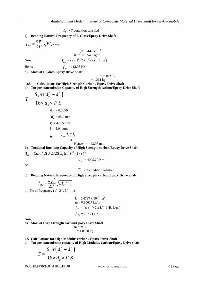
b) Meshing for Composite Drive Shaft
Figure 5 Meshed E-Glass Epoxy Drive Shaft
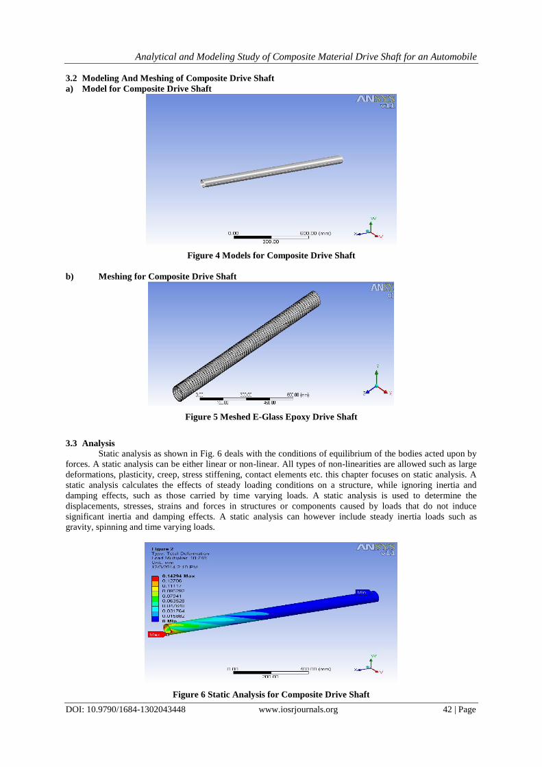
3.3 Analysis
Static analysis as shown in Fig. 6 deals with the conditions of equilibrium of the bodies acted upon by
forces. A static analysis can be either linear or non-linear. All types of non-linearities are allowed such as large
deformations, plasticity, creep, stress stiffening, contact elements etc. this chapter focuses on static analysis. A
static analysis calculates the effects of steady loading conditions on a structure, while ignoring inertia and
damping effects, such as those carried by time varying loads. A static analysis is used to determine the
displacements, stresses, strains and forces in structures or components caused by loads that do not induce
significant inertia and damping effects. A static analysis can however include steady inertia loads such as
gravity, spinning and time varying loads.
Figure 6 Static Analysis for Composite Drive Shaft
Analytical and Modeling Study of Composite Material Drive Shaft for an Automobile
DOI: 10.9790/1684-1302043448 www.iosrjournals.org 43 | Page
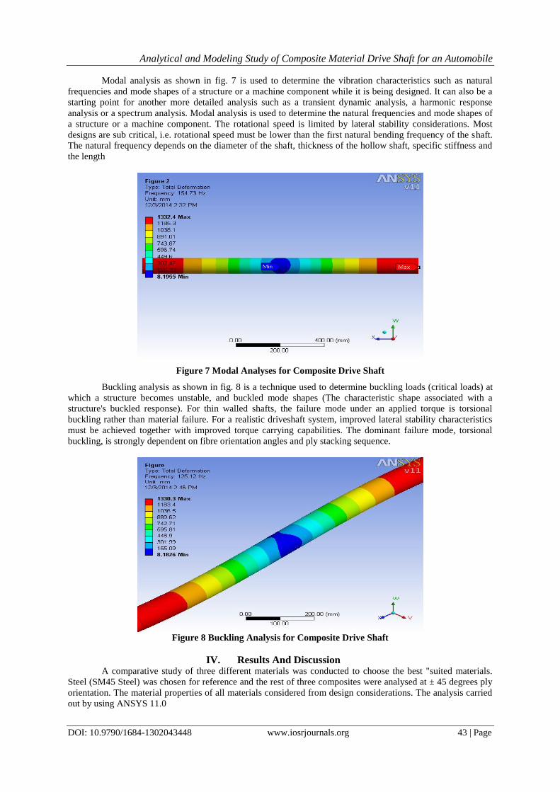
Modal analysis as shown in fig. 7 is used to determine the vibration characteristics such as natural
frequencies and mode shapes of a structure or a machine component while it is being designed. It can also be a
starting point for another more detailed analysis such as a transient dynamic analysis, a harmonic response
analysis or a spectrum analysis. Modal analysis is used to determine the natural frequencies and mode shapes of
a structure or a machine component. The rotational speed is limited by lateral stability considerations. Most
designs are sub critical, i.e. rotational speed must be lower than the first natural bending frequency of the shaft.
The natural frequency depends on the diameter of the shaft, thickness of the hollow shaft, specific stiffness and
the length
Figure 7 Modal Analyses for Composite Drive Shaft
Buckling analysis as shown in fig. 8 is a technique used to determine buckling loads (critical loads) at
which a structure becomes unstable, and buckled mode shapes (The characteristic shape associated with a
structure's buckled response). For thin walled shafts, the failure mode under an applied torque is torsional
buckling rather than material failure. For a realistic driveshaft system, improved lateral stability characteristics
must be achieved together with improved torque carrying capabilities. The dominant failure mode, torsional
buckling, is strongly dependent on fibre orientation angles and ply stacking sequence.
Figure 8 Buckling Analysis for Composite Drive Shaft
IV. Results And Discussion A comparative study of three different materials was conducted to choose the best "suited materials.
Steel (SM45 Steel) was chosen for reference and the rest of three composites were analysed at ± 45 degrees ply
orientation. The material properties of all materials considered from design considerations. The analysis carried
out by using ANSYS 11.0
Analytical and Modeling Study of Composite Material Drive Shaft for an Automobile
DOI: 10.9790/1684-1302043448 www.iosrjournals.org 44 | Page
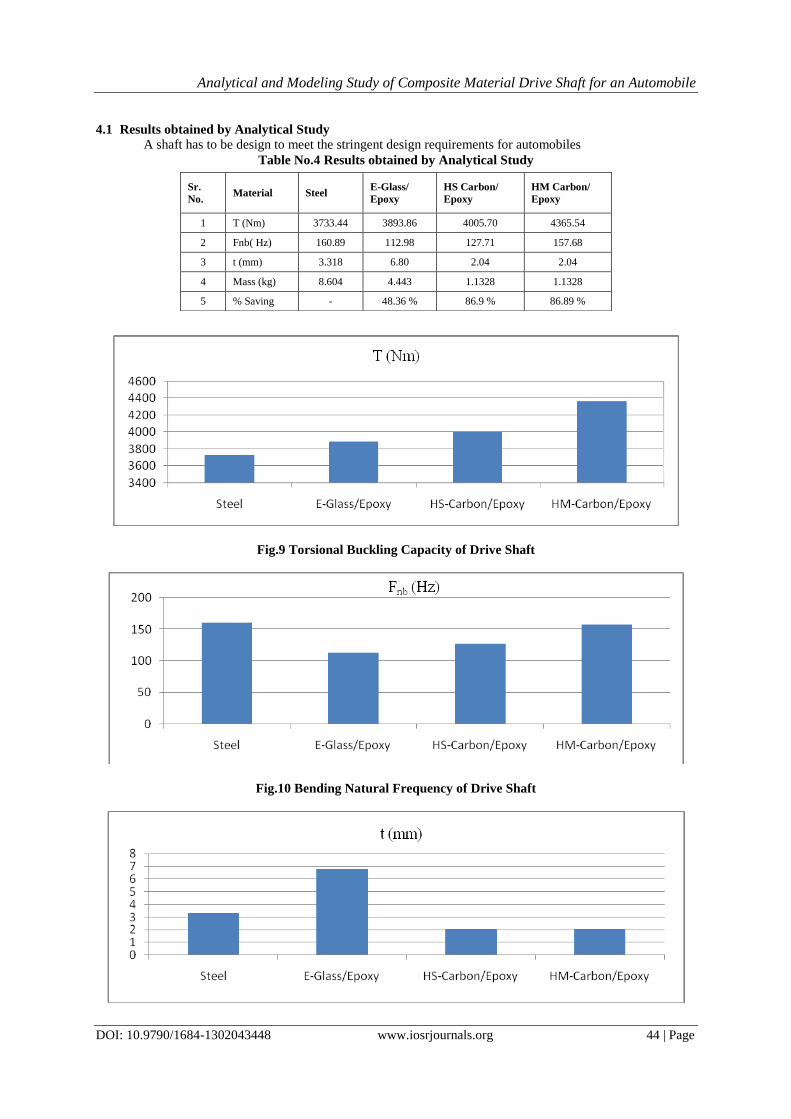
4.1 Results obtained by Analytical Study A shaft has to be design to meet the stringent design requirements for automobiles
Table No.4 Results obtained by Analytical Study
Fig.9 Torsional Buckling Capacity of Drive Shaft
Fig.10 Bending Natural Frequency of Drive Shaft
Sr.
No. Material Steel
E-Glass/
Epoxy
HS Carbon/
Epoxy
HM Carbon/
Epoxy
1 T (Nm) 3733.44 3893.86 4005.70 4365.54
2 Fnb( Hz) 160.89 112.98 127.71 157.68
3 t (mm) 3.318 6.80 2.04 2.04
4 Mass (kg) 8.604 4.443 1.1328 1.1328
5 % Saving - 48.36 % 86.9 % 86.89 %

Analytical and Modeling Study of Composite Material Drive Shaft for an Automobile
DOI: 10.9790/1684-1302043448 www.iosrjournals.org 45 | Page
Fig.11 Thickness of Drive Shaft
Fig.12 Mass of the Drive Shaft
4.2 Results comparison obtained by Analytical and Modeling study for drive Shaft
A comparison between the results obtained based on theoretical calculations and the results obtained
from the ANSYS 11.0.work bench has been carried out. For this purpose, the drive shaft of the automobile has
been idealized as a hollow cylindrical shaft. It is then subjected to same load theoretically and in finite element
solver. The comparisons of results shows a very close range (Table No. 5) conformance, which has been plotted
Table No.5 Results comparison obtained by Analytical and Modeling study for drive Shaft
Material Analytical Study Modeling Study
T(Nm) fn(hz) M(Kg) T(Nm) fn(hz) M(Kg)
Steel 3733.44 160.89 8.604 3815.94 158.25 8.504
E-Glass/Epoxy 3893.86 112.98 4.261 4087.77 111.03 4.511
HS-Carbon/Epoxy 4005.70 127.71 1.0868 4189.12 125.12 1.1283
HM-Carbon/Epoxy 4365.54 157.68 1.0561 4450.38 154.72 1.1272
Nature of graph (fig. 13, 14, 15) for above comparison is as shown below:
Fig.13 Comparative results of Analytical study and Modeling study for Torsional Buckling Capacity
Drive Shaft-

Analytical and Modeling Study of Composite Material Drive Shaft for an Automobile
DOI: 10.9790/1684-1302043448 www.iosrjournals.org 46 | Page
Fig.14 Comparative results of Analytical study and Modeling study for Bending Natural Frequency of
Drive Shaft
Fig.15 Comparative results of Analytical study and Modeling study for Mass of Drive Shaft
4.3 Stress and Strain distribution along
It’s been found that the stresses developed in E-Glass/Epoxy drive shaft are under permissible limit.
The values of stresses developed within the shaft with its permissible limit are shown in Table No. 6 below;
Table No. 6 Stress and Strain distribution along thickness of E-Glass/Epoxy drive Shaft
Material Allowable Predicted Stress Design is
Stress(MPa) (MPa) OK/NOT
E-Glass/Epoxy
St1 = 400 119.78 OK
St2= 20 19.38 OK
S12 = 36 23.45 OK
SC1 = - 400 - 87.34 OK
SC2 = -20 -18.11 OK
S12= -36 -26.08 OK
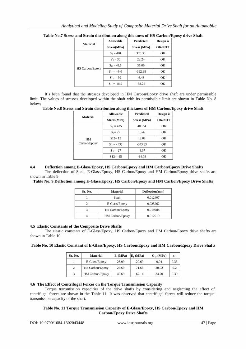
It’s been found that the stresses developed in HS Carbon/Epoxy drive shaft are under permissible limit.
The values of stresses developed within the shaft with its permissible limit are shown in Table No. 7 below;
Analytical and Modeling Study of Composite Material Drive Shaft for an Automobile
DOI: 10.9790/1684-1302043448 www.iosrjournals.org 47 | Page
Table No.7 Stress and Strain distribution along thickness of HS Carbon/Epoxy drive Shaft
Material Allowable Predicted Design is
Stress(MPa) Stress (MPa) OK/NOT
HS Carbon/Epoxy
St1 = 440 378.36 OK
St2 = 30 22.24 OK
S12 = 48.5 35.06 OK
Sc1 = - 440 -392.38 OK
SC2 = -30 -6.43 OK
S12 = -48.5 -38.25 OK
It’s been found that the stresses developed in HM Carbon/Epoxy drive shaft are under permissible
limit. The values of stresses developed within the shaft with its permissible limit are shown in Table No. 8
below;
Table No.8 Stress and Strain distribution along thickness of HM Carbon/Epoxy drive Shaft
Material Allowable Predicted Design is
Stress(MPa) Stress (MPa) OK/NOT
HM
Carbon/Epoxy
St1 = 435 406.54 OK
St2= 27 13.47 OK
S12= 15 12.09 OK
Sc1 = - 435 -343.63 OK
SC2= -27 -8.07 OK
S12= -15 -14.08 OK
4.4 Deflection among E-Glass/Epoxy, HS Carbon/Epoxy and HM Carbon/Epoxy Drive Shafts
The deflection of Steel, E-Glass/Epoxy, HS Carbon/Epoxy and HM Carbon/Epoxy drive shafts are
shown in Table 9
Table No. 9 Deflection among E-Glass/Epoxy, HS Carbon/Epoxy and HM Carbon/Epoxy Drive Shafts
Sr. No. Material Deflection(mm)
1 Steel 0.012407
2 E-Glass/Epoxy 0.025262
3 HS Carbon/Epoxy 0.019288
4 HM Carbon/Epoxy 0.012919
4.5 Elastic Constants of the Composite Drive Shafts
The elastic constants of E-Glass/Epoxy, HS Carbon/Epoxy and HM Carbon/Epoxy drive shafts are
shown in Table 10
Table No. 10 Elastic Constant of E-Glass/Epoxy, HS Carbon/Epoxy and HM Carbon/Epoxy Drive Shafts
Sr. No. Material Ex (MPa) Ey (MPa) Gxy (MPa) ν12
1 E-Glass/Epoxy 28.99 20.69 9.94 0.35
2 HS Carbon/Epoxy 26.69 71.68 20.02 0.2
3 HM Carbon/Epoxy 40.69 62.14 34.20 0.39
4.6 The Effect of Centrifugal Forces on the Torque Transmission Capacity
Torque transmission capacities of the drive shafts by considering and neglecting the effect of
centrifugal forces are shown in the Table 11 It was observed that centrifugal forces will reduce the torque
transmission capacity of the shaft.
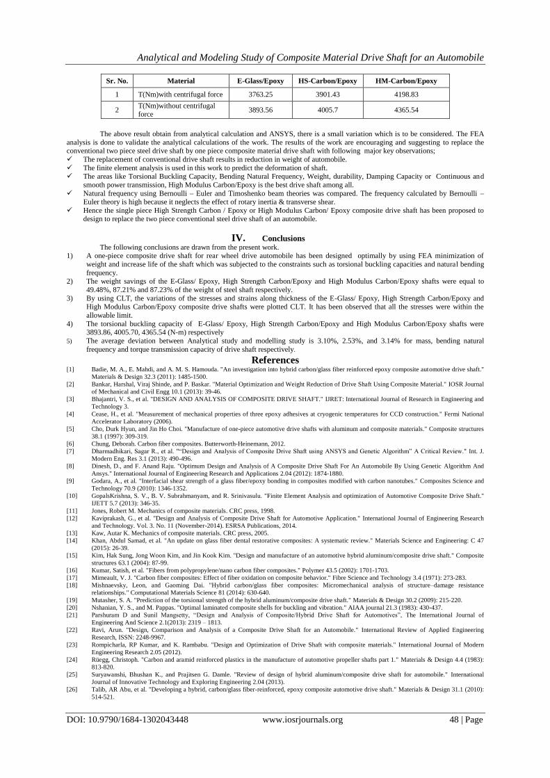
Table No. 11 Torque Transmission Capacity of E-Glass/Epoxy, HS Carbon/Epoxy and HM
Carbon/Epoxy Drive Shafts
Analytical and Modeling Study of Composite Material Drive Shaft for an Automobile
DOI: 10.9790/1684-1302043448 www.iosrjournals.org 48 | Page
Sr. No. Material E-Glass/Epoxy HS-Carbon/Epoxy HM-Carbon/Epoxy
1 T(Nm)with centrifugal force 3763.25 3901.43 4198.83
2 T(Nm)without centrifugal force
3893.56 4005.7 4365.54
The above result obtain from analytical calculation and ANSYS, there is a small variation which is to be considered. The FEA
analysis is done to validate the analytical calculations of the work. The results of the work are encouraging and suggesting to replace the conventional two piece steel drive shaft by one piece composite material drive shaft with following major key observations;
The replacement of conventional drive shaft results in reduction in weight of automobile.
The finite element analysis is used in this work to predict the deformation of shaft. The areas like Torsional Buckling Capacity, Bending Natural Frequency, Weight, durability, Damping Capacity or Continuous and
smooth power transmission, High Modulus Carbon/Epoxy is the best drive shaft among all.
Natural frequency using Bernoulli – Euler and Timoshenko beam theories was compared. The frequency calculated by Bernoulli – Euler theory is high because it neglects the effect of rotary inertia & transverse shear.
Hence the single piece High Strength Carbon / Epoxy or High Modulus Carbon/ Epoxy composite drive shaft has been proposed to
design to replace the two piece conventional steel drive shaft of an automobile.
IV. Conclusions
The following conclusions are drawn from the present work. 1) A one-piece composite drive shaft for rear wheel drive automobile has been designed optimally by using FEA minimization of
weight and increase life of the shaft which was subjected to the constraints such as torsional buckling capacities and natural bending
frequency. 2) The weight savings of the E-Glass/ Epoxy, High Strength Carbon/Epoxy and High Modulus Carbon/Epoxy shafts were equal to
49.48%, 87.21% and 87.23% of the weight of steel shaft respectively.
3) By using CLT, the variations of the stresses and strains along thickness of the E-Glass/ Epoxy, High Strength Carbon/Epoxy and High Modulus Carbon/Epoxy composite drive shafts were plotted CLT. It has been observed that all the stresses were within the
allowable limit.
4) The torsional buckling capacity of E-Glass/ Epoxy, High Strength Carbon/Epoxy and High Modulus Carbon/Epoxy shafts were 3893.86, 4005.70, 4365.54 (N-m) respectively
5) The average deviation between Analytical study and modelling study is 3.10%, 2.53%, and 3.14% for mass, bending natural
frequency and torque transmission capacity of drive shaft respectively.
References [1] Badie, M. A., E. Mahdi, and A. M. S. Hamouda. "An investigation into hybrid carbon/glass fiber reinforced epoxy composite automotive drive shaft."
Materials & Design 32.3 (2011): 1485-1500.
[2] Bankar, Harshal, Viraj Shinde, and P. Baskar. "Material Optimization and Weight Reduction of Drive Shaft Using Composite Material." IOSR Journal
of Mechanical and Civil Engg 10.1 (2013): 39-46.
[3] Bhajantri, V. S., et al. "DESIGN AND ANALYSIS OF COMPOSITE DRIVE SHAFT." IJRET: International Journal of Research in Engineering and
Technology 3.
[4] Cease, H., et al. "Measurement of mechanical properties of three epoxy adhesives at cryogenic temperatures for CCD construction." Fermi National
Accelerator Laboratory (2006).
[5] Cho, Durk Hyun, and Jin Ho Choi. "Manufacture of one-piece automotive drive shafts with aluminum and composite materials." Composite structures
38.1 (1997): 309-319.
[6] Chung, Deborah. Carbon fiber composites. Butterworth-Heinemann, 2012.
[7] Dharmadhikari, Sagar R., et al. "“Design and Analysis of Composite Drive Shaft using ANSYS and Genetic Algorithm” A Critical Review." Int. J.
Modern Eng. Res 3.1 (2013): 490-496.
[8] Dinesh, D., and F. Anand Raju. "Optimum Design and Analysis of A Composite Drive Shaft For An Automobile By Using Genetic Algorithm And
Ansys." International Journal of Engineering Research and Applications 2.04 (2012): 1874-1880.
[9] Godara, A., et al. "Interfacial shear strength of a glass fiber/epoxy bonding in composites modified with carbon nanotubes." Composites Science and
Technology 70.9 (2010): 1346-1352.
[10] GopalsKrishna, S. V., B. V. Subrahmanyam, and R. Srinivasulu. "Finite Element Analysis and optimization of Automotive Composite Drive Shaft."
IJETT 5.7 (2013): 346-35.
[11] Jones, Robert M. Mechanics of composite materials. CRC press, 1998.
[12] Kaviprakash, G., et al. "Design and Analysis of Composite Drive Shaft for Automotive Application." International Journal of Engineering Research
and Technology. Vol. 3. No. 11 (November-2014). ESRSA Publications, 2014.
[13] Kaw, Autar K. Mechanics of composite materials. CRC press, 2005.
[14] Khan, Abdul Samad, et al. "An update on glass fiber dental restorative composites: A systematic review." Materials Science and Engineering: C 47
(2015): 26-39.
[15] Kim, Hak Sung, Jong Woon Kim, and Jin Kook Kim. "Design and manufacture of an automotive hybrid aluminum/composite drive shaft." Composite
structures 63.1 (2004): 87-99.
[16] Kumar, Satish, et al. "Fibers from polypropylene/nano carbon fiber composites." Polymer 43.5 (2002): 1701-1703.
[17] Mimeault, V. J. "Carbon fiber composites: Effect of fiber oxidation on composite behavior." Fibre Science and Technology 3.4 (1971): 273-283.
[18] Mishnaevsky, Leon, and Gaoming Dai. "Hybrid carbon/glass fiber composites: Micromechanical analysis of structure–damage resistance
relationships." Computational Materials Science 81 (2014): 630-640.
[19] Mutasher, S. A. "Prediction of the torsional strength of the hybrid aluminum/composite drive shaft." Materials & Design 30.2 (2009): 215-220.
[20] Nshanian, Y. S., and M. Pappas. "Optimal laminated composite shells for buckling and vibration." AIAA journal 21.3 (1983): 430-437.
[21] Parshuram D and Sunil Mangsetty, “Design and Analysis of Composite/Hybrid Drive Shaft for Automotives”, The International Journal of
Engineering And Science 2.1(2013): 2319 – 1813.
[22] Ravi, Arun. "Design, Comparison and Analysis of a Composite Drive Shaft for an Automobile." International Review of Applied Engineering
Research, ISSN: 2248-9967.
[23] Rompicharla, RP Kumar, and K. Rambabu. "Design and Optimization of Drive Shaft with composite materials." International Journal of Modern
Engineering Research 2.05 (2012).
[24] Rüegg, Christoph. "Carbon and aramid reinforced plastics in the manufacture of automotive propeller shafts part 1." Materials & Design 4.4 (1983):
813-820.
[25] Suryawanshi, Bhushan K., and Prajitsen G. Damle. "Review of design of hybrid aluminum/composite drive shaft for automobile." International
Journal of Innovative Technology and Exploring Engineering 2.04 (2013).
[26] Talib, AR Abu, et al. "Developing a hybrid, carbon/glass fiber-reinforced, epoxy composite automotive drive shaft." Materials & Design 31.1 (2010):
514-521.