Centralized analytic software? Yes, an analytic software ...
J OURNAL OF PRO PU LSION AND PoweR Vol. 10, No. 5, Sept. - Oct. 1994
Analytic Design Methods for Wave Rotor Cycles
Edwin L. Resler Jr.,* Jeffrey C. Mocsari ,t and M. Razi Nalimt Cornell University, Ithaca, New York 14853
A procedure to design a preliminary wa,•e rotor cycle for any application is presented. To complete a cycle with heat addition there arc two separate-but related-design steps that must be performed . Selection of a wave configuration determines the allowable amount of heat added in any case, and the ensuing wave pattern requires associated pre~sure discharge conditions to allow the pr•w·e~~ In he made cyclic. This procedure, when applied, givtS a first estimate of the cycle performance and the necessary information for proceeding to the next step in the design process, namely, the application of a characteristic-based or other appropriate detai led onedimensional wave calculation that locates more precisely the proper porting around the periphery of the wave rotor. Examples of the design procedure are given to demonstrate its utility and generality. These examples also illustrate the large gains In performance that might be realized with the use of wave rotor enhanced propulsion cycles.
Nomenclature a sound speed cp specific heat at constant pressure L length of rotor channel M Mach number m mass P " rightward moving" characteristic quantity.
speed (u + a) p pressure Q "leftward moving·· characteristic quantity.
speed (u - a) q heat (added or rejected) per unit mass R gas constant s = entropy per unit mass T temperature
time interval u fluid velocity ( + to right, - to left) w cycle work per unit mass x position along channel y fraction of unit mass flow y specific heat ratio, 1.4 TJ efficiency p density
Subscripts eft effective turbine inlet temperature s refers to shock 1 total or stagnation quantity x = quantity at engine exit 0 ambient flight conditions
Introduction
T HE wave rotor is a device that provides direct energy exchange between gases. An introduction to wave rotor
technology can be found in the lite rature . ' 3 An important
Presented as Paper 93-2523 at the AIAA/SAE/ASME/ASEE 29th Joint Propulsion Conference and Exhibit. Monterey, CA. June 28-30. 1993: received July 19. 1993; revision received Jan. 14. 1994: accepted for publication Jan. 15. 1994. Copyright © 1993 by the American Institute of Aeronautics and Astronautics. Inc. All rights reserved.
• Joseph Newton Pew Jr. Professor of Engineering. Sibley School of Mechanical and Aerospace Engineering. 150 Upson Hall. Retired Fellow AIAA.
tGraduate Student. /.erospace Engineering. 290 Grumman Hall. Student Member ATAA.
683
application of wave rotors is for gas turbine topping cycles, an idea that dates back to the early 1940s.45
The wave rotor improves the overall performance of a conventional engine by allowing the combustor exit temperature to be higher than the maximum a llowable turbine inle t temperature. The performance of conventional gas turbine engines depends on the a llowable operating temperature of turbine blade materials. Attempts to c ircumvent this limitation have renewed interest in wave rotor topping cycles. '' •~
This article presents a design procedure for engine cycles utilizing a wave rotor to e nhance cycle performance. Attention is paid in particular to the general features common to all wave rotor cycles. To demonstrate the procedure a few cycle examples are given with an estimate of their performance.
The discussion focuses mainly on the thermodynamic cycles possible utilizing unsteady flow. A "wave rotor cycle" refers to the thermodynamic engine cycle resulting from a wave rotor design. A " wave cycle" refers to a periodic unsteady now pattern in the rotor channels. There is no ·'particular" o r "best" cycle, but there are general features presented that all cycles must possess. It is these general features that are the subject here. Applying these geperal features allows one to design a particular wave rotor cycle for any given application and to estimate its performance. Other interesting applications for unsteady flows not involving heat addition also follow the general principles discussed here.
An unsteady flow cycle utilized for propulsion involves using shock waves to replace conventional compressors and unsteady expansion rather than conventional steady flow expansion in a nozzle. Shock waves driven by heat addition to the working fluid constitute a "wave turbine-compressor combination" that allows one to avoid the restrictions on peak temperature imposed by materia l properties that limit the performance of present day propulsion systems. The use of a wave rotor cycle results in a higher efficiency as well as an increase in power as compared with present cycles.
The wave rotor cycles treated here involve a wave rotor made up of straight constant area wave channels so that no shaft power is derived from the wave rotor itself. For the cycles discussed here the wave rotor is situated between the conventional compressor and conventional turbine.
The conventional compressor not only charges the wave rotor but is also used to flush it so a new wave cycle can commence. T he conventional compressor is also the source of cooling a ir for the wave rotor which allows it to handle hot combustion gases. A conventional turbine is used whe re possible, intercepting hot flows issuing from the wave rotor chan-

684 RESLER , MOSCARL AND NALIM: DESIGN METHODS FOR WAVE ROTOR CYCLES
nels. The term "possible," implies in this context, a certain peak temperature for the turbine inlet that cannot be exceeded.
An unsteady expansion, as employed in a wave rotor, cools the flow isentropically as it would be cooled in a conventional turbine which extracts "enthalpy" from the flow, but does not require any blades. This has implications for the control of the NO. emissions from engines. 16.t 7
Comparison of wave engine cycles with conventional powerplant systems are conveniently made on the basis of Tcfl· Ter, is defined as the turbine inlet temperature of the cycle that would be necessary to produce the same power in a conventional engine operating with ideal components (100% efficient compressor and turbine) in the maximum power mode. This mode requires the temperature leaving the ideal compressor to be equal to the square root of the product of the compressor inlet temperature and the turbine inlet temperature. Tcrc is calculated by Eq. (1):
(1)
It is assumed in this article that present engines can operate, at best, at 3000°R (1667 K); therefore, equivalent turbine inlet temperatures in excess of this are a measure of the improvement possible with wave rotor cycles.
In all cases the wave rotor cycles discussed will include shock wave losses. For all the calculations in this article, C~' is assumed constant and y == 1.4.
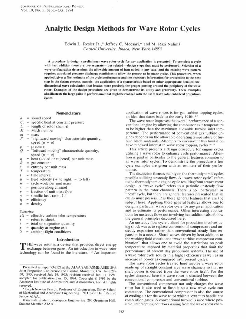
Wave Rotor Cycles The general features of a wave cycle are shown in Fig. 1.
The particular cycle portrayed is entitled "MINQ wave cycle." The essential waves are presented as a function of time as they progress through a single wave channel. A wave rotor is made up of a multitude of these channels arranged around a cylinder which is rotating at constant speed. Thus, the time in this diagram can be reinterpreted as an angle about the periphery of the wave rotor. An observer situated at a fixed angle at an open end of the rotor would observe a steady flow resulting from the unsteady cyclic flow in the channels going by. The flow velocity in the rotor is defined positive to the right. The discussion below concerns the necessary conditions to achieve an actual cycle.
There are generally eight regions of any cycle. To demonstrate the general wave cycle design procedure it will be
TIME
Coolin Blowby
X Distance along Wave Channel
Characteristics --- Contact Surface - Shockwave
To Combustor via Turbines if appropriate
Fig. I MINQ wave diagram.
applied first to the MINQ cycle. Start with the introducti~n of air from a compressor in region 1. The compressor air sweeps out the residual gases, 8, by means of the shock wave between regions 7 and 8. These regions not only contain residual gases from the previous cycle but also residual waves (not shown). The shock wave clearly sweeps out the residual gases; to deal with the residual waves requires more discussion. The flow in region 1 is introduced at M = -1. This is desirable as the port size for a given flow is then the smallest. This also prevents wave disturbances from the rotor channel from reaching the compressor, and the waves remaining from the preceding events are trapped in the channel.
There are two types of waves in the channel, those moving with the velocity (u + a), which we name P waves, and those moving with the velocity (u - a), which we choose to call Q waves. What we have chosen to call "waves," in accord with popular usage, are the mathematical characteristics of the set of differential equations describing the conservation laws for the one-dimensional unsteady flow in the rotor channels, along which a Riemann invariant is constant. (In our case, P = 5a + u and Q = 5a - u are the invariants, if the ratio of specific heats of the gas is a constant and equal to 1.4.) In port 1 the P waves are not allowed to enter because u = -a, whereas the Q waves emanating from port l all have the same value of Q. After the compressor gas clears the channel it is in some cases desirable to allow some blowby to supply cooling where necessary. Note that the extent of this region of blowby is arbitrary. If the cooling blowby gases are routed through a turbine after leaving the wave rotor, the cooling effect in this ideal case is "free," in that it does not affect the ideal Brayton cycle efficiency.
A stationary sidewall (stationary sidewalls are shown as cross-hatched regions in Fig. 1) is imposed at the end of the channel to stop the blowby flow. This results in a hammer shock wave that brings the flow in the tube to rest (thick line between 1 and 2). The Q waves pass through this shock wave with little change in their value of Q. These Q waves then reflect off the wall as P waves of constant value, since at the wall u = 0, soP = Q. Since behind the shock wave both P and Q are constant and equal to each other, the flow is at rest in region 2.
A more detailed calculation using the mathematical theory of characteristics can be used to determine the actual shock wave strength and trajectory that varies along the channel in just the required manner to, in effect, sweep out the residual waves. An apt description of this particular hammer shock wave for those familiar with a popular video game is the " pac man shock." The pressure that must be supplied at the boundary at 7 to force these desired wave phenomena to occur depends on other details of the cycle. Any wave pattern may be reduced to a uniform flow (it need not be a zero velocity flow) with this "wave trapping" procedure.
The hammer shock wave that brings the compressor flow to rest has a strength that can be estimated if it is assumed that it returns with. uniform speed. The strength of this shock can be found using Eq. (2), which relates the states before and after the shock in terms of the "shock wave Mach number," M,, :
u, - u2 = -~ (M,, __ 1_) a, 6 M .• 1
(2)
Solving Eq. (2) forM, " (note u2 = 0), provides an expression for the strength of the hammer shock:
-1 - \11 + 4(5/6M1) 2
10
6M,
(3)
Recall that M1 = -1; therefore, M., = 1.76, giving a static pressure ratio rise of 3.47. The hammer shock acts as a " wave
RESLER. MOSCARI. AND NALIM: DESIGN METHODS FO R WAVE ROTO R CYCLES 6R5
diffuser." If the wave was isentropic, the pressure rise would be 3.58. Thus , the shock wave diffuser operates with an efficiency of 97% . Note that the " unsteady wave diffuser" with shock wave losses included increases the pressure more than a perfect steady-flow diffuser would.
The gas in region 2 is then subjected to another shock wave (2 to 3). This shock wave is produced when the side plate that stopped the flow ends, and hot, high-pressure combustion gas is introduced into the wave channel at the left side of the figure . The compressor gas is further compressed by a factor of about 4 by this shock wave. The wave rotor cycle thus provides a static pressure rise ratio of 12-15 above the pressure supplied by the conventional compressor. Note that the compression process is in two stages, mimicking the O swatitch diffuser and avoiding the losses that would be incurred if only one larger shock wave were used.
A port on the right side (port 3) is situated to remain open while collecting the shock wave compressed gases. These hot compressed gases are then directed either to a turbine or directly to the combustor depending on the desired cycle. The conditions that determine the heat addition in terms of the shock wave strength are the continuity of pressure and velocity across the gas interface 3-4, along with accounting for the mass that is returned to create this shock wave. If heat is added at constant static pressure in the combustor and all the flow is returned to the wave rotor, the temperature ratio 4 to 3 is equal to the ratio of the port sizes 4 to 3, as is easily verified.
Equation (4) is a statement of mass conservation between the mass exiting at port 3 and the fraction y of that mass returning through port 4
(4)
where t4 is the time port 4 remains open . The mass of gas in the tube at station 2, p2L. is taken as the unit mass of the cycle. All of the fresh air charge at 2 exits the rotor at port 3. For this particular cycle (MINQ), t4 has been chosen such that the first P wave generated when port 4 is closed reaches the right end of the channel ·simultaneously with the 3-4 interface. This time is given by Eq. (5):
(5)
Across the gas interface u4 = u3 and p4a~ = p3a5. Combining these relations with Eqs. (4) and (5) one finds the quadratic equation
(6)
Solving Eq. (6) for the sound speed ratio across the contact surface allows one to find the heat added in the combustor in terms of the strength of shock wave 2-3:
(MINQ)
~ = -M3 + VMf + (4/y)(p/ p2)
a3 2 (7)
Naturally, the shock wave strength is determined by the heat addition. For computational purposes, it is easier to assume the shock wave strength and solve the last equation for the temperature rise across the combustor.
The closing of the port at 4 is immediately followed by the opening of exhaust port 5 to a lower pressure causing an unsteady expansion that reverses the flow. The static temperature change from 4 to 5 is given by
T5 =- [5 - M 3(a3/a4)]2
(8) T4 5 - M 5 .
Since the expansion wave is unsteady there is a decrease in both total temperature and total pressure from 4 to 5. The total temperature of the flow, processed by this expansion. decreases by at least a factor of 516 (if M5 = - 1). For temperatures near 3000oR (1667 K) this means this expansion reduces the temperature out of the combustor by at least 500oR (278 K). Until the weak shock formed by the closing port 3 returns to the left side of the channel, the flow out of port 5 is steady and an axial turbine might be situated to intercept this flow.
The amount of mass exiting at port 5 depends on the t ime it takes this shock wave to return to the left side of rotor. By solving the differential equation for the trajectory of this wave, assuming it is weak, an expression for the time port 5 is open t5 is found:
This result is used to calculate the mass leaving the rotor at port 5 with respect to the reference mass at station 2 (m~ = PzL):
Similarly, the amount of energy leaving the wave rotor at port 5 can be calculated to estimate the amount of work that can be extracted in a conventional turbine receiving this steady flow.
The pressure at 7 must be chosen to accommodate the required shock wave 7 to 8 that flushes the channel and sets up the flow that traps the waves so the cycle can be completed. The wave pattern in the channel is tending toward a uniform zero velocity condition as region 7 is approached, and so we neglect the kinetic energy term in region 7 in this approximation and assume the processes occurring from 6 to 7 , the " To Expander" region of Fig. 1, are isentropic. This module of the calculation depends on the first module describing heat addition, only through the total entropy change to 7. The shock strength M,1 is found by the following procedure. Using the boundary conditions at the gas interface between 8 and 1, uR = u 1 and PR = p 1, and the shock wave relations between states 7 and 8 , an expression for (a,la 1) can be found:
(lla)
and so
( ) 6 M,,
- M 1 S (Mi1 - 1) ( 11 b)
and from normal shock relations
Ps P1 7M;, - 1 - =- = p, p, 6
(llc)
For y = 1.4, the entropy change from 7 to 1 is
s7 - S1 = 7
R I.
p, II
PI (lld)
By combining Eqs. (llb-lld) an expression for M.,7 is found:
(lle)
The principles discussed so far are sufficient to describe any wave rotor cycle with wave trapping, and have been applied

686 RESLER, MOSCARI. AND NALIM: DESIGN METHODS FOR WAVE ROTOR CYCLES
to the particular cycle MINQ. The various regions of the cycle can now be analyzed separately to find the thermodynamic work that might be accomplished "piece wise," or alternately, a "thermodynamic cycle work" for the whole cycle can be found by determining the overall rejected heat. 18 Since both of these approaches must give the same answer it is convenient to use both of them and compare them as a check of the computation.
All cycles of interest are open, with the open part being a constant pressure process. Following the entropy changes of the gas as it is processed , we must get the same value when following the detailed changes through the cycle to the discharge state (p_., T.., where Px = p0 ) as proceeding from the ambient temperature T0 to T.. via a constant pressure process. If the final entropy of the gas when it leaves the propulsion system is sx, and of the entering flow s0 , then the exiting temperature Tx is
(12)
and the rejected cycle heat qR per unit mass is
(13)
The heat added, qR is determined by the cycle details alrea_dy discussed . The cycle work per unit mass is (qA - qR) . ThiS procedure can be followed for the various parcels of fluid following different paths to p0 until they have all been taken into account. The choice as to what device is used to extract the cycle power is a matter of design.
Further details of a particular wave cycle require a more sophisticated treatment. A design procedure utilizing mathematical characteristics has been developed for use with a computer,17 and the detailed wave pattern for one of the cases discussed below will be presented.
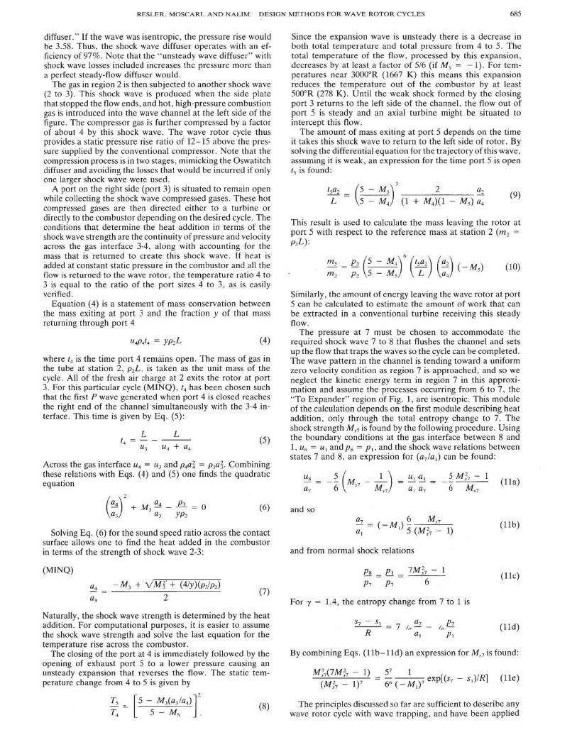
A similar analysis can be used for other cycles; another named MAXQ is shown in Fig. 2. For this cycle port 4 is kept open until the wave created by the closure of the compressed gas outflow arrives at the left side. This allows for the maximum port 4 opening time for a given state at 3 and chosen y , and corresponds to the maximum possible heat addition. Port 4 may be closed at any time giving rise to all those cycles with "intermediate Qs. "
For the MAXQ cycle the sound speed ratio across the contact surface following the procedure for MINQ is given in Eq. (14):
(MAXQ)
a4 = M3 + VM~ + (4/y)(pj p2)
a3 2 (14)
Wave cycles can be designed with any value of a4 /a3 between the maximum and minimum values. Each case involves a different relation for a4 /a3 •
The gas entering port 4, this time, flows through the rotor and out port 5. Across the expansion fan, P4 = P5, and the temperature ratio from 4 to 5 is
(15)
Similar to the MINQ case, the flow exiting the rotor. is steady until the first wave of the expansion reflects from wall closing port 4 and returns to right side of rotor. The time that port 5 remains open 15 , is again obtained by solving the differential equation for the trajectory of this wave:
t5a2 = (5 + M5)
3
L 5 + M4 (1 2 a2
M4)(1 + M5) a4 (16}
TIME
Cooling Blow by
To Combustor via Turbines if Appropriate
Fig. z MAXQ wave diagram.
The mass exiting the rotor at 5 with respect to the mass at station 2 for the MAXQ case is given by Eq. (17):
: : = ~: (~ : z:r ('~2) (::)(M~) (17)
As in the MINQ case , the wave processes from region 6 to 7 are assumed to be isentropic. Again, the pressure at 7 that allows the required shock 7 ·8 to form needs to be determined in order to complete the cycle. Equation (11e) from the MINQ treatment is still valid in this case.
This completes the description of the procedure to construct cycles that allow one to estimate performance and provide the data for the use of more sophisticated computational techniques to further design the hardware to accomplish the cycle performance. This procedure gives estimates of performance that agree very closely with those found from a detailed one· dimensional flow simulation using the method of characteristics adopted for a computer. 17
MINQ Cycle Performance In this section a few cycles patterned after the MINQ dia·
gram will be explored to present the possible advantages of utilizing a wave rotor cycle and demonstrate a few of the varied possibilities.
Helicopter
The first cycle we investigate we name " helicopter," since it is assumed in this example that it is desirable to produce shaft work cmly. The wave rotor follows a conventional compressor. A block diagram of this cycle is given in Fig. 3a. In this example the gases pass directly from behind the shock wave 2-3 in the wave rotor to the combustor , and all the flow is returned to the wave rotor. Use is made of the steady flow in region 5 by directing it to an axial turbine where the inlet temperature is maintained at the assumed maximum temper· ature for turbine blades of 3000°R (1667 K).
A large combustion chamber loss is incurred in this case, because use is not made of the total pressure mismatch be· tween the hot gas, 4 , and the cooler gas, 3. Some device is necessary to process the gases expanding from regions 6 to 7 . This device, situated to intercept the gases from the expander region, must be cooled by blowby gases as the mean temperature of these gases is above 3000°R. The gas exiting port 8, since it leaves the rotor channel with constant prop· erties, could also be directed to an axial turbine. As in the

RESLER, MOSCI\RI , AND NA LI M : pESIGN MI?.THODS FOR ~AVE ROTOR C YC LES 687
Inlet
a)
~ ' 1.8 - ---.- ---.,----,----.!----,
~ 1.7 . - · -c··-~r-· a: 1.6 + ---<'>----- -~ · r ,
~ " --l~"--- · ~;---l--1 ~ : :: ~~~~·:~~~.t~:··~-.~~·:-.-.c ... -.-.~~· ... ~~ .. ~.~-: .. : .. ;:w;::~--·· ~ 1.2 .•.... ·- ·1 ············· .. ·1········ .. ........ . ...... j ....... ··-e ··-·--·····--·-L ........... ~ .......... 1
........................ ..... - ................ 1
~ I. : + .................. ..,~,...._ .......... ....._,_._ ........ ....._,_._ ........ ....._,_._._._....., 0.4 0.45 o.s o.ss 0.6 0.65
b) EQUlV ALENCE RATIO
~ ~ 4100
~ t 4000
~~ , .. ~~
3800
3700
3600 0.4 0.4S . O.S O.SS 0.6 0.6S
c) EQUIVALENCE RATIO
Fig. 3 Helicopter a) block diag.ram, b) efficiency and powe.r .ratio curves, and c) effective turbine inlet temperature.
previous cycle all the power produced is via a shaft as might be desirable for helicopter applications.
For comparison purposes choose a maximum power Brayton cycle as mentioned in the Introduction. Efficiency ratio, power ratio, and effective turbine inlet temperature are quantitative measures used to compare the wave cycle performance with that of the ideal maximum power Brayton cycle. T he efficiency ratio is defined as
eff ratio = Tlw••• cy<lc
17or .. yaon
and the power ratio is
(18)
(19)
The effective turbine inlet temperature was defined in Eq. (!). By comparing ideal cycles it is expected that real cycles might scale in the same ratios.
The performance curves for helicopter are shown in Figs. 3b and 3c. Note the large gain in performance possible using the wave rotor cycle.
M = 0.8 Transport
Next, a rotor cycle ts treated that might be appropriate for subsonic flight conditions appropriate to modern day trans-
Inlet
a)
b)
4200
Iii 4000 g2
~~
~~ 3800
3600
i~ 3400
i'l
3200~~~~~~~-4~~~~~~ 0.3S 0.4 0.4S O.S O.SS 0.6 0.6S 0.7
C) EQUIVALENCE RATIO
Fig. 4 Subsonic transport a) block diag.ram, b) efficiency a nd powe.r curves, and c) effective turbine inlet temperature.
ports. The cycle schematic is shown in Fig. 4a. In this case the flow issuing from port 5 is again util ized in an axial turbine. In the case considered, the work from this axial turbine is more than sufficient to power the conventional compressor that feeds and purges the wave rotor channels.
In this cycle the flow in the expander region is utilized in a jet thrust nozzle and there is no need to utilize the cooling blowby flow. The unsteady process in the wave rotor expansion allows the nozzle and turbine drive temperature to differ by more than 800oR ( 444 K) with the nozzle receiving the hotter flow. This is not possible in a conventional engine unless after-burning, with its associated losses, is used. Since the turbine inlet temperature is within our chosen limits, no cooling in addition to the conventional blade cooling required to reach 3000°R (1667 K) is required in this cycle.
The advantages gained are slightly larger than in the previous case, as can be seen in Figs. 4b and 4c. Again, the improvement from utilizing wave rotor cycle technology is large and indicates the desirability of exploring further the possibilities. Associated noise and propulsive efficiency considerations are not considered.
Figure 5 is a computer-generated wave diagram for the subsonic transport case where the total pressure ratio of the conventional compressor is 21.48. T his cycle is a MINQ cycle. T he port data used to generate the computer diagram is given in Table 1. T he pressure used for port 7 is the value calculated via the procedure outlined in the Cycle Overview section. This is a specific example of the use of analytical calculations

688 ·RESLER. MOSCARI. AND NALIM: DESIGN METHODS FOR WAVE ROTOR CYC LES
Table 1 Subsonic transport boundary conditions
Description T. R p , atm M
Flight conditions 400 0.185 0.82 Port 1 801 2.10 -1 Shock (2-3) 2.778 Port 3 2926 64.4 1.293 Port 4 5474 64.4 0.945 Port 5 2500 4.14 -1 Station 7 1583 0.838 Shock (7-8) 1.514 Port 8 2105 2.100 -0.62
X
Fig. 5 Computer generated wave diagram for subsonic transport case.
to provide the necessary boundary conditions for a more detailed computer model of the cycle.
Sup.,.sonic Transport
The final example presented is a case similar to the subsonic transport in cycle geometry , but for a supersonic flight Mach number of 2.5, flying at an altitude of 60,000 ft. Because the ram pressure in this case is considerable, the possibilities are even more impressive than in the subsonic case. The range of equivalence ratios possible in this case extends all the way to stoichiometric.
The performance is summarized in Figs. 6a-6c. There are three ranges of operation (I, II, III in Fig. 6a). At low power, (I) , the drive turbine situated at port 5 is sized to drive the conventional compressor required to purge the combustion products. At intermediate equivalent ratios, (II), there is more than sufficient power in the gas leaving port 5 and entering the turbine to drive the required conventional compressor. The required conventional compressor is small at low power, increases until the turbine blade temperature limit forces mbre wave compression and a resulting decrease in the pressure ratio required of the conventional compressor, until finally the conventional compressor is not needed at all (Ill). In this stage the wave rotor cycle operates with ram and wave compression only. Over the entire operating range the performance of the cycle is more efficient and supplies more power than possible with current technology.
a)
b)
~2 ~~ ~~ ~ffi p c)
1.35 .,.--~-...---.---,--,--,---""""""\'-.....,
0.2 0.3 0.4 0.5 0.6 0.7 0.8 0.9
EQUIVALENCE RATIO
0.2 0.3 0.4 0.5 0.6 0.7 0.8 0.9
EQUIVALENCE RATIO
7000
6000
5000
4000
3000
2000
. . i i
·-·J-·!-··+ ·f··J .. I .. _ ...... r_ ........ i .............. r·-···-···r ··-··+·-·--···-~ ......... _.,!. ;
i ! I ! i I I ! . .
~F:r=:r=FFFT~ tooo~~~~~~~~~~~~~~
0.2 0.3 0.4 0.5 0.6 0.7 0.8 0.9
EQUIVALENCE RATIO
Fig. 6 Supersonic transport a) efficiency ratio curve, b} power ratio curve, and c) effective turbine inlet temperature.
Conclusions A convenient design procedure that, if followed , insures
workable wave rotor cycles, has been presented. The essential features of any propulsion cycle are outlined and several examples are presented to demonstrate the procedure and quantify the possible gains to be realized with rotor enhanced power cycles. .
· fhe initial design procedure provides the basis for a more detailed analysis for coupling the wave rotor to other power producing components. In this article a possible turbine blade operating temperature of 3000°R (1667 K) is assumed, although wave rotor enhancement of power cycles can be realized whatever the assumed turbine blade temperature. In wave rotor cycles the turbine blades are not subject to the highest temperatures of the cycle, allowing combustion chamber technology to be decoupled from the turbine blade performance.
The gains possible using wave rotor technology are considerable resulting in increases of power by a factor near 2, coupled with better efficiencies as compared with current practice. The versatility of the cycles discussed seem to open new possibilities for this technology, which if exploited would provide more efficient and powerful propulsion systems.

RESLER. MOSCARI. AND NALIM: DESIGN METHOOS F'OR WAV E ROTOR C YCLES 689
Acknowledgments This wo rk was carried out with support from NASA Lewis
Research Center, C leveland, Ohio. The contributions of G. P. Mathis and J . R. Hendricks are acknowledged.
References
'Azoury. P. H., Engineering Applications of Unsteady Flow, Wiley, New York. 1992. Chap. 4. ~Azoury, P. H .. "An Int roduction to the Dynamic Pressure Ex
changer." The lnstillltion of Mechanical Engineers Proceedings , Vol. 180. Pt. I. 1965-66.
'Foa. J . V .. Elememsof Flight Propulsion, Wiley. New York, 1960, Chap. 10.
•Meyer. A., "Recent Developments in Gas Turbines," Mechanical Engineering. Vol. 69. No. 4. 1947. pp. 273- 277.
5Kantrowitz. A., Hertzberg, A., McDonald, E. E., and Resler, E. L.. Jr.. " Heat Engines Based on Wave Processes," Contract Rept. to the Office of Naval Research N6-0NRT08. March 1949.
''Mathis, G. P., "Wave Enhanced Gas Turbine Engine Cycles," M.S. Thesis, Cornell Univ., Ithaca, New York. 1991.
'Shreeve. R. P., and Mathur, A. (ed.), Proceedings of the 1985 ONRINAVAIR Wave Rotor Research and Technology Workshop, Naval Postgraduate School, Monterey, CA. May 1985.
"Taussig. R. T. , and Hertzberg, A .• "Wave Rotors for Turbomachinery," Machinery for Direct Fluid-Fluid Energy Exchange, Aerospace Div ., American Society of Mechanical Engineers AD-07, Dec. 1984.
"Taussig. R. T., "Wave Rotor Turbofan Engines for Aircraft."
Machinery for Direct Fluid-Fluid Energy Exchange. Aerospace Div., American Society of Mechanical Engineers AD-07, Dec. 1984.
10Zauner. E., Chyou. Y., Walraven. F., and Althaus, R. , "Gas Turbine Topping Stage Based on Energy Exchangers: Process and Pe rformance. ·• Gas Turbine and Aeroengine Congress. American Society of Mechanical Engineers 93-GT-58, Cincinnati. OH , May 1993.
"Wilson, J ., and Fronek D., " Initial Re~ults from the NASALewis Wave Rotor Experiment ." AIAA Paper 93-2521, June 1993.
'1Paxson , 0., "A Comparison Between Numerically Modeled and
Experimentally Measured Loss Mechanism in Wave Rotors:· AIAA Paper 93-2522. June 1993.
' 3Lcar , W., Jr., and Candler. G., "Analysis of the Accuracy of Wave Rotor Boundary Conditions Using a Novel Computational Method," AIAA Paper 93-2524, June 1993.
'"Welch, G. , "Two-Dimensional Numerical Study of Wave Roto r Flow Dynamics," AIAA Paper 93-2525, June 1993.
' 5Larosiliere, L. , "Three-Dimensional Numerical Simulation of Gradual Opening in a Wave Rotor Passage," ATAA Paper 93-2526, June 1993.
' 6Nalim, M. R .. Mocsari, J . C. , and Resler, E . L., Jr. , "Wave Cycle Design for NOx-Limitcd Wave Rotor Core Engines for High Speed Propulsion," Gas Turbine and Aeroengine Congress. American Society of Mechanical Engineers 93-GT-426, Cincinnati, OH, May 1993.
17Nalim , M. R .. "Wave Cycle Design for Wave Rotor Engines with Limited Nitrogen-Oxide Emissions," Ph.D. Dissertation. Cornell Univ., Ithaca, New York , Jan. 1994.
' 8Reslcr, E. ·L. , Jr., and Greenberg, B. M., "Propulsion over a Wide Mach Number Range ," NASA CR 182267, March 1989.
Recommended Reading from Progress in Astronautics and Aeronautics
~~---High-Speed w-Fiight Propulsion Systems
----- --- S.N.B. Murthy and E. T. Curran, editors
This new text provides a cohesive treatment of the complex Issues In high speed prppulslon as well as introductions to the current capabilities for addressing several fundamental aspects of high-speed vehicle propulsion development. Nine chapters cover Energy Analysis of HighSpeed Flight Systems; Turbulent Mixing In Supersonic Combustion Systems; Facility Requirements for Hypersonic Propulsion System Testing; and more. Includes more than 380 references, 290 figures end tables, and 185 equations.
1991, 537 pp, illus, Hardback
Place your order today! Call 1-800/682-AIAA
ISBN 1-56347-011-X AJAA Members $54.95 Nonmembers $86.95 Order 1: V-137 (830)
·AIAA~ AmenQII lnttituto of Aoronautics ~nd Aslroovutia
Publication' Customer Selvice, 9 Jay Gould Ct, P.O. Box 7.53, Waldotf, MD 20604 FAX 301/843.0159 Phone 1-8()(V682-2422 9 a.m.- 5 p.m. Eastem
Sales Tax: CA mldec1ts, 8.25%; DC, 6%. For~ and to.lllllg add S4.751or 1-4 books (cal for rates lor higher qUIIItilies). O!dets under S100.00 must be prepaid. Foreign ordets must be fllepald and klcludt a $20.00 post~~ suroharge. Please allow 4 weelcs loriSMI)'. Prices are su~ to change without notk:e. Returns wll be ~ed withWl 30 days. ~oo-U.S. residents are responsible for Pil""ent of any rues required by their government.