Analysis on Aircraft Brake Squeal Problem Based on...
12
Research Article Analysis on Aircraft Brake Squeal Problem Based on Finite Element Method Ming Zhang, 1 Ran Xu, 1 and Hong Nie 1,2 1 Key Laboratory of Fundamental Science for National Defense-Advanced Design Technology of Flight Vehicle, Nanjing University of Aeronautics and Astronautics, Nanjing 210016, China 2 State Key Laboratory of Mechanics and Control of Mechanical Structures, Nanjing University of Aeronautics and Astronautics, Nanjing 210016, China Correspondence should be addressed to Ming Zhang; [email protected] Received 15 February 2017; Revised 5 April 2017; Accepted 19 April 2017; Published 28 May 2017 Academic Editor: Hikmat Asadov Copyright © 2017 Ming Zhang et al. is is an open access article distributed under the Creative Commons Attribution License, which permits unrestricted use, distribution, and reproduction in any medium, provided the original work is properly cited. Brake squeal phenomenon is a problem that has been long studied using multiple methods and theories. Finite Element Method (FEM) has been applied to the study of brake squeal problem. First, a disc brake model has been established. Complex mode theory has been applied to the mode analysis and unstable vibration modes can be extracted subsequently. e form of unstable vibration mode has been studied. en, transient dynamic simulation using explicit dynamic method has been performed. Response in both time and frequency domain has been analyzed. Two methods have been compared, considering accuracy and calculation consumption. en, the effect of different parameters such as coefficient of friction, stiffness, and brake force fluctuation frequency on squeal phenomenon has been analyzed. It can be found that coefficient of friction and the brake stiffness have a positive correlation with the extent of brake squeal phenomenon, while the frequency of brake force fluctuation should remain as low as possible. Aſterwards, a ring-shaped layer of viscoelastic damping material is constrained to outer margin of the stator to restrain the unstable modal. is method can change the vibration nature and improve the brake squeal problem. 1. Introduction Along with the rising requirement of comfort in the field of civil aviation, brake noise problem has gained great attention because it considerably affects passengers’ convenience [1–3]. Aircraſt brake system generates vibration during its normal working process, followed by noise inevitably. It has been over 60 years since foreign researchers began working on brake squeal problem, while domestic researchers merely initiated their study in 1980s. In terms of the classification of squeal problem, a universal standard has not yet been put forth. However, researchers agree on naming different types of brake noise according to their respective vibration frequency. Most of the researchers tend to divide squeal phenomenon into three kinds. First type of brake noise possesses a frequency range from 100 Hz to 1 kHz, which is relatively low. is type of brake noise comes from the stick- slip motion between friction surfaces [4]. Applying other materials whose coefficient of friction is stable about slip speed could ease this type of brake noise effectively. Second type of brake noise is generated due to the occurrence of modal coupling among brake parts, with a frequency range between 1 kHz and 3 kHz. e third type of brake noise is generally caused by modal response of brake discs, whose frequency is between 3 kHz and 15 kHz. e last two types of brake noise are oſten named as “squeal,” which has always been an important issue in the field of brake noise research [5–8]. Brake squeal phenomenon brings tremendous oscillation load to both brake mechanism and landing gear structure, which greatly interferes with pilot’s regular flight control and passengers’ comfort. Serious brake squeal may even damage the entire brake system [9]. As a result, it is quite necessary to study aircraſt brake squeal problem thoroughly. In the field of experiment, many researchers have found that it is very hard to replicate brake squeal in the lab [10]. Moreover, noise generated in the lab does not have a stable frequency and sound pressure level [11–14]. During Hindawi International Journal of Aerospace Engineering Volume 2017, Article ID 3982851, 11 pages https://doi.org/10.1155/2017/3982851
Transcript of Analysis on Aircraft Brake Squeal Problem Based on...

Research ArticleAnalysis on Aircraft Brake Squeal Problem Based onFinite Element Method
Ming Zhang1 Ran Xu1 and Hong Nie12
1Key Laboratory of Fundamental Science for National Defense-Advanced Design Technology of Flight VehicleNanjing University of Aeronautics and Astronautics Nanjing 210016 China2State Key Laboratory of Mechanics and Control of Mechanical Structures Nanjing University of Aeronautics and AstronauticsNanjing 210016 China
Correspondence should be addressed to Ming Zhang zhm6196nuaaeducn
Received 15 February 2017 Revised 5 April 2017 Accepted 19 April 2017 Published 28 May 2017
Academic Editor Hikmat Asadov
Copyright copy 2017 Ming Zhang et al This is an open access article distributed under the Creative Commons Attribution Licensewhich permits unrestricted use distribution and reproduction in any medium provided the original work is properly cited
Brake squeal phenomenon is a problem that has been long studied using multiple methods and theories Finite Element Method(FEM) has been applied to the study of brake squeal problem First a disc brake model has been established Complex mode theoryhas been applied to the mode analysis and unstable vibration modes can be extracted subsequently The form of unstable vibrationmode has been studied Then transient dynamic simulation using explicit dynamic method has been performed Response inboth time and frequency domain has been analyzed Two methods have been compared considering accuracy and calculationconsumptionThen the effect of different parameters such as coefficient of friction stiffness and brake force fluctuation frequencyon squeal phenomenon has been analyzed It can be found that coefficient of friction and the brake stiffness have a positivecorrelation with the extent of brake squeal phenomenon while the frequency of brake force fluctuation should remain as lowas possible Afterwards a ring-shaped layer of viscoelastic damping material is constrained to outer margin of the stator to restrainthe unstable modal This method can change the vibration nature and improve the brake squeal problem
1 Introduction
Along with the rising requirement of comfort in the field ofcivil aviation brake noise problem has gained great attentionbecause it considerably affects passengersrsquo convenience [1ndash3]Aircraft brake system generates vibration during its normalworking process followed by noise inevitably It has beenover 60 years since foreign researchers began working onbrake squeal problem while domestic researchers merelyinitiated their study in 1980s In terms of the classificationof squeal problem a universal standard has not yet beenput forth However researchers agree on naming differenttypes of brake noise according to their respective vibrationfrequency Most of the researchers tend to divide squealphenomenon into three kinds First type of brake noisepossesses a frequency range from 100Hz to 1 kHz which isrelatively low This type of brake noise comes from the stick-slip motion between friction surfaces [4] Applying othermaterials whose coefficient of friction is stable about slip
speed could ease this type of brake noise effectively Secondtype of brake noise is generated due to the occurrence ofmodal coupling among brake parts with a frequency rangebetween 1 kHz and 3 kHz The third type of brake noise isgenerally caused by modal response of brake discs whosefrequency is between 3 kHz and 15 kHz The last two typesof brake noise are often named as ldquosquealrdquo which has alwaysbeen an important issue in the field of brake noise research[5ndash8]
Brake squeal phenomenon brings tremendous oscillationload to both brake mechanism and landing gear structurewhich greatly interferes with pilotrsquos regular flight control andpassengersrsquo comfort Serious brake squeal may even damagethe entire brake system [9] As a result it is quite necessary tostudy aircraft brake squeal problem thoroughly
In the field of experiment many researchers have foundthat it is very hard to replicate brake squeal in the lab[10] Moreover noise generated in the lab does not have astable frequency and sound pressure level [11ndash14] During
HindawiInternational Journal of Aerospace EngineeringVolume 2017 Article ID 3982851 11 pageshttpsdoiorg10115520173982851
2 International Journal of Aerospace Engineering
FWD OUTBDBrake rod center bolt
AFT brakerod
Torque tubepedestal bushing
Torque tubeheat shield
Rotorinserts
Pressure plate
Pistonadjusterassembly
Brake tiebolts amp nuts
INBD
Brake attachmentpin
Bushing
Cross bolt
Piston housingtorque armbushing
Brake rod
Piston housingbushing
Inner cylinderfork lug
Figure 1 Schematic figure of aircraft brake system
experiment Oberst and Lai discovered that even brake forcespeed and temperature are stable the sound pressure levelof brake force still has a considerable straggling tendency[15] Beloiu and Ibrahim discovered that even during onesingle experiment progress there can still be an undeniablestraggling tendency in sound pressure level contact force offriction surface and coefficient of friction [16] So far no clearresult can be concluded from the experiments
As the theoretical research proceeds over time four maintheories dealing with brake squeal problem have been putforward by researchers They are stick-slip theory lock-sliptheory negative slope of friction force theory and modalcoupling theory The previous two theories emphasize stick-slip property the latter two theories concentrate on structuralinstability [17] In all researchers have been studying thecause and influence factor of brake squeal problem for a longtime But unfortunately a complete and universal theory tohandle brake squeal problem has not been invented yet [18]However there is no doubt that modal coupling and modalresponse method show promising prospect in coping withbrake squeal problem
Combining with previous researchersrsquo experience anFEM model of an actual aircraft brake system has been con-structed Complex mode analysis is thoroughly introducedand applied to the aircraft brake model Complex eigenvaluesare extracted and analyzed The vibration property of certaintypical unstable frequencies has been analyzed With thehelp of explicit dynamic analysis transient dynamic anal-ysis has been performed on the aircraft brake model Thedisplacement response in both time domain and frequency
domain has been acquired Several influence factors arestudied by applying complex mode method
2 Aircraft Disc Brake Modeling
Schematic figure of a typical aircraft disc brake is shownin Figure 1 It mainly consists of pistons torque tubesbrake rods and a set of brake discs that stack alternativelyHydraulic system provides pressure for the brake procedurePistons empowered by hydraulic system push a set of gangedstators against a set of ganged rotors so brake force canbe generated by friction between brake discs Brake forceis transferred to the entire landing gears structure throughwheel axis and piston houses Among the primary brakemechanisms carbon brake discs carry out the most crucialfunctions of the brake system which is friction Carbon brakediscs enable the aircraft to completely stop moving whilethe plane is taking off and landing this makes the discs keycomponents in the brake system
A simplified brake model is built according to theFEM modeling principles Subsequent improvements areconducted by setting up contact friction mesh and elementproperties This reliable model is the foundation stone forfurther analysis
21 Physical Modeling Brake discs model are currentlyapplied in actual type of civil aircraft The detailed CADmodels are given in CATIA software All the parts are madeof carbon composite material whose Youngrsquos modulus is80GPa density is 1800 kgm3 and coefficient of friction on
International Journal of Aerospace Engineering 3
Figure 2 Simplified model of stator
Figure 3 Simplified model of rotor
the contact surface is 03 Because straggling brake discs arethe key objects in the analysis several tiny holes fillets andchamfers are simplified or removed to ensure amore qualifiedmesh Finished discs models are shown in Figures 2ndash4
Import these simplified disc models into ABAQUS soft-ware and construct the assembly model according to theiractual position The completed assembly model is shown inFigure 5
22 Improvements of the Model During brake procedurecontact behavior exists in multiple positions Simulatingcontact behavior both conveniently and accurately is the keyto analyzing brake squeal problem Construct surface-surfacecontact pair on every contact surface of the brake disc sofriction effect can be built in the software Contact propertyincludes penalty function so coefficient of friction can be
Figure 4 Simplified model of baseplate
Figure 5 FEMmodel of assembly
introduced There are two kinds of contact algorithms inABAQUS software which are small sliding and finite slidingSmall sliding algorithm is applied because subsequent anal-ysis does not contain large scale of displacement comparedwith the size of element
In order to satisfy accuracy and time consumptionrequirements of FEM simulation partitions of the entiremodel are divided based on geometry appearance of themodel Afterwards an exquisite structural mesh can beestablished Comparison between directly generated meshand partition based mesh is shown in Figure 6 It is obviousthat by setting up partitions mesh becomes neater andmore concise which provides great accuracy and efficiencyfor further analysis There are 11440 elements on rotormodel 11165 elements on stator model and 8136 elements onbaseplate model
Finally verify the entire mesh condition for excessivedistortion for excessive errors At last FEM model of aircraftbrake is finished
3 Complex Mode Analysis
After finishing constructing of the FEM model of the brakesystem subsequent squeal analysis can be performed Thischapter concentrates on complex mode theory unstablevibration modes are extracted and unstable vibration modesare analyzed
4 International Journal of Aerospace Engineering
Figure 6 Comparison between different mesh strategies
31 Theory of Complex Mode Analysis In order to researchbrake squeal problem modal analysis must be conductedto discover intrinsic vibration property of the entire modelModal analysis means decoupling the differential equationswhich demonstrate vibration property of the system andtransform physical coordinate into modal coordinate sorelative modal parameters can be deduced
As for ordinary real mode vibration analysis mass matrixand stiffness matrix are both symmetric and positive definiteDamping matrix is a linear representation of mass andstiffness matrix which can be decoupled Moreover naturalvibration modes are real vectors which are orthogonal tomass stiffness and damping matrices Therefore modalcoordinate is capable of simplifying the differential equationsHowever in the aircraft disc brake model damping matrixcannot be linearly represented bymass and stiffness matricesAs a result modal parameters turn to be complex instead ofreal
For an ordinary damped vibration system damping forceis in direct proportion to velocity The vibration differentialequation is
119872 + 119862 + 119870119883 = 119865 (1)
where119872 119862119870119883 and 119865 are all matrices representing massdamping stiffness displacement and force matrices Thisequation can also be illustrated in matrix form
[119862 119872119872 0 ]
+ [
119870 00 minus119872]119883 = 1198650 (2)
Assume 2119873 times 1 state vector119883 is
119883 = 119883 (3)
So (2) can be simplified as
119860 + 119861119883 = 119865119860 = [119862 119872
119872 0 ]
119861 = [119870 00 minus119872]
(4)
Equation (4) is the state equation of complex modeanalysis Matrix 119860 and matrix 119861 are both of 2119873 times 2119873 sizeFor free vibration 119865 becomes zero matrix Assume root ofthe equation is
119883 = 120595119890120582119905 = 120595120582119890120582119905 (5)
where 120595 is
120595 = [1206011 120601119873] (6)
So (4) can be solved and 2119873 eigenvalues and eigenvectorscan be acquired
1205821 120582lowast1 1205822 120582lowast2 120582119873 120582lowast119873 120595112059511205821
120595lowast1120595lowast1 120582lowast1 120595119873120595119873120582119873
120595lowast119873120595lowast119873120582lowast119873 (7)
Plug eigenvectors to original vibration equation (4)
(119860120582 + 119861)120595 = 0 120595 = 120595120595120582 (8)
for No 119903mode it can be shown as
(119860120582119903 + 119861)120595119903 = 0 (9)
Combine with eigenvector of No 119904 mode It can beinferred that
120595119879119904 (119860120582119903 + 119861)120595119903 = 0120595119879119903 (119860120582119904 + 119861)120595119904 = 0
(10)
Because 119860 and 119861 are both symmetric
120595119879119903119860120595119904 = 120595119879119904 119860120595119903120595119879119903 119861120595119904 = 120595119879119904 119861120595119903
(11)
So it is evident that
120595119879119903119860120595119904 (120582119903 minus 120582119904) = 0 (12)
Therefore orthogonal property of complexmode analysisis
120595119879119904 119860120595119903 = 0120595119879119904 119861120595119903 = 0
(13)
120582119903 is the complex modal frequency of the vibration system120595119903 is the complex modal eigenvector These two parametersalways come in conjugate pairs According to the complexmode properties a systemwith119873 degrees of freedom has 2119873eigenvalues and eigenvectors
International Journal of Aerospace Engineering 5
32 FEM Analysis with Complex Mode Method It is vitalto calculate undamped vibration frequency and vibrationmodes before any complex frequency analysis in ABAQUSsoftware Besides static analysis step must be added to exertactual working conditions on the entire model such asrotation speed and pressure so accuracy can be ensuredTherefore analysis steps of the entire simulation are listedbelow
Step one is the static mechanic analysis By exertingpressure on outward stator surface brake force can be sim-ulated and contact interactions among parts are establishedMoreover stress status under actual working condition can beachieved Stress may alter the stiffness matrix and influencesubsequent frequency simulation
Step two is generating rotating velocity InABAQUS staticmechanic analysis there are no rotating freedoms for nodesof 3D solid objects so it is unable to exert rotation on rotorsas boundary condition as usual So special keywordsmust beadded to the model to solve this problem Categorize everynode of rotors under one set named as ldquorotorrdquo Then usekeywords ldquolowastMotion Rotationrdquo to establish relevant rotationaxis and velocity
Step three is the extraction of natural frequency ofundamped model This step is the foundation of complexmode analysis
Step four is the complex mode analysis Complex fre-quency and complex eigenvalues are calculated and recorded
Complex eigenvalues are all complex numbersThe imag-inary part of complex eigenvalue indicates the complex vibra-tion frequency while real part of eigenvalue denotes stabilityof vibration Complex modal damping equals to oppositenumber of real part divided by imaginary part Therefore apositive real part means a negative modal damping whichultimately leads to unstable vibration
There is another factor that needs to be taken intoconsideration The existing material damping and structuraldamping are not included in the model so total dampingeffect in the vibration system is smaller than it should bethis may cause the result to be more unstable As a resultconsidering existing practical analysis experience vibrationmodes with a modal damping less than minus001 are determinedto be unstable complex modes which lead to brake squealphenomenon
In this analysis eigenvalue data are extracted by historyoutput and mapped in Figure 7
The slope in the figure represents a minus001 damping Dotsabove the slope mean unstable vibration mode Correspond-ing frequency can be seen in the figure as well There are 36unstable vibration modes in the analysis totally
There has been no certain conclusion that the strongersqueal is the more serious negative damping exists Andtheoretical improvement of the relationship between squealextent and negative damping value has not been conductedyet However based on past experiment experience andcomplex mode simulation results the tendency of seriousbrake squeal phenomenon does relate to the real part valueof corresponding eigenvalueThus it is practical to determinethe brake squeal extent by analyzing real part of the eigen-value
6000 8000 10000 12000 14000 16000 180004000Imaginary part of eigenvalue
minus6000
minus4000
minus2000
0
2000
4000
6000
Real
par
t of e
igen
valu
e
Figure 7 Complex eigenvalue scattergram
In the analysis conducted in this chapter unstable vibra-tion mode firstly emerges at 4930Hz It is clear that unstablemodes do not distribute uniformly In fact they clusteraround several certain values 5 kHz 8 kHz 10 kHz 12 kHz135 kHz and 162 kHz are intervals where most unstablemodes exist As a result the frequencies of brake squealalso exist in those intervals So far the frequency of brakesqueal phenomenon has been calculated from complexmodeanalysis
33 Properties of Unstable Vibration Modes To take a deeperlook at the unstable vibration property it is vital to analyzespecific orders of unstable vibration modes
There are two major vibration mode categories in-planemode and out-of-planemode [19] According to past researchexperience each mode is mainly dominated by only onecategory of vibration while the other category has little effect
Vibrationmodes dominated by out-of-planemotion pos-sess obvious out-of-plane vibration tendency This tendencycan be described by static diameter and static circle Asfor modes dominated by in-plane motion circumferentialdirection and radial direction are analyzed There will atleast be one static diameter along circumferential directionmotion while there is no static diameter or static circle alongradial direction Some typical unstable vibration modes areshown in Figure 8 Contour shows the displacement along itsmajor direction of every vibration mode 119865119903 represents thereal part of corresponding eigenvalue It is noteworthy thatthe value of displacement has been normalized so it does notreflect any actual length
Properties of unstable vibration modes can be concludedfrom the figures Most of the unstable modes are dominatedby out-of-plane vibration only a few exceptions exist Amongthese exceptions radial direction vibration plays the maincharacter In terms of vibration modes whose frequency isunder 10 kHz brake discs have similar vibration tendencyOn the other hand if vibration frequency exceeds 10 kHzdifferent brake discs vibrate differently with more staticdiameters Moreover brake discs near the baseplate vibratefiercer under high frequency
6 International Journal of Aerospace Engineering
f = 4971Hz fr = 649 f = 5161 Hz fr = 283 f = 7572 Hz fr = 297 f = 9859 Hz fr = 2287
f = 16123Hz fr = 1987f = 13269 Hz fr = 821f = 13185 Hz fr = 564f = 12010 Hz fr = 4727
Figure 8 Typical unstable vibration modes
4 Transient Dynamic Analysis
In order to study brake squeal problem more precisely non-linear properties must be taken into consideration Explicitdynamic method is applied for transient dynamic analysis onbrake squeal problem Fourier transformation is also appliedto analyze vibration property in the frequency domain
41 Theory of Explicit Dynamic Explicit dynamic analysisfocuses on differences about timeNo simultaneous equationsneed to be constructed or solved Convergence is not aproblem either Dynamic analysis always offers a result nomatter how rough the model is However the increment steplength is heavily influenced by the FEM element quality Thenumber of increment steps is also very tremendous so it takesa lot of time and resource to conduct the analysis
ABAQUS applies central difference method for solvingtransient dynamic problems The FEM process can be shownas follows
119872(119905) = 119891(119905)ex minus 119891(119905)in (14)
In the equation stands for acceleration vector and119872 is the mass matrix 119891ex represents external load and 119891inrepresents internal load During explicit simulations thereare certain relations between velocity and displacement
(119905+05Δ119905) = (119905minus05Δ119905) + Δ119905(119905+Δ119905) + Δ119905(119905)2 (119905)119909(119905+Δ119905) = 119909(119905) + Δ119905(119905+Δ119905)(119905+05Δ119905)
(15)
In the equation 119905plusmn05Δ119905 stands for the middle incrementstep during calculations and Δ119905 is the step length Difference
instead of differential is applied in explicit dynamic analysisso step length must be short enough to ensure sufficientaccuracy
42 Explicit Dynamic Analysis Explicit analysis step isunable to coexist with previous static analysis steps so awhole new set of analysis steps are needed During the linearperturbation steps in the last chapter the entire system isstable in every increment step and time does not participatein the actual simulation while in dynamic analysis time isan important parameter which heavily influences the analysisprocedure
Therefore the new analysis steps need further modifica-tion Keywords are not able to exert rotation to the rotors soa reference point is established at the axis of rotation Thencouple every node of rotor model with the reference pointso that boundary conditions can be exerted at the referencepoint as well as the rotors Rotation and brake force are bothgradually applied according to time as shown in Figure 9
After finishing applying rotation speed simulation con-tinues for 001 seconds to observe and analyze the vibrationwhich grants a 100Hz lower limit for frequency domainanalysis
Change contact algorithm into finite sliding methodbecause the relative sliding is large compared to the size ofsingle element According to the purpose of the transientdynamic analysis extra history output must be added Picka certain observation point on the rotor and record thedisplacement data every 5ms which ensures a high samplingdensity After completing the simulation map the curves ofdisplacements along three directions as shown in Figures 10and 11 In this analysis119883 is the axial direction and119884 and119885 are
International Journal of Aerospace Engineering 7
Rota
tion
spee
d (r
ads
)Br
ake f
orce
(N)
Total time (s)
Total time (s)
65
10500
01 015
Figure 9 Applying process of rotation speed and brake force
Along Y axisAlong Z axis
minus03
minus02
minus01
000102
Disp
lace
men
t (m
)
005 010Time (s)
Figure 10 Displacement curves of 119884 and 119885 direction
the directions in the disc plane In Figure 10 the blue curveindicates displacement along 119884 direction and brown curvereflects 119885 direction
From these two figures it can be concluded that rotationdominates the motion along 119884 and 119885 axis no obvious highfrequency vibration takes place This matches the result fromcomplex mode analysis where in-plane unstable vibrationmodes are minority In terms of 119883 axis direction theamplitude of the displacement is merely among millimeterswhich is very tiny comparedwith the size of brake disc At 001secondswhen brake force is applied high frequency vibrationtakes place As brake force gradually increases the vibration
005 01 015001234567
Time (s)
Along Xaxis
Disp
lace
men
t (m
m)
Figure 11 Displacement curve of119883 direction
times10minus4
times10minus3
times104
Time domain
Frequency domain
0152 0154 0156015 016 01620158t (s)
0123456
y
06 08 1 12 14 16 1804Frequency (Hz)
25
2
15
1
05
0
Figure 12 Displacement curves in time and frequency domain
becomes more acute To study the vibration property infrequency domain extract the last 001-second curve andthen use MATLAB to perform Fourier transformation thenFigure 12 can be achieved
From Figure 12 it is evident that acute vibration takesplace around 5 kHz 8 kHz 10 kHz 12 kHz and 15 kHz inter-vals By comparing this result with result from last chapterit can be concluded that squeal phenomenon around 5 kHz10 kHz and 12 kHz has been accurately predicted by complexmode analysis while 8 kHz 135 kHz and 15 kHz vibrationfrequency do not match the result from complex modeanalysis These phenomena are called ldquooverpredictionrdquo andldquomissing orderrdquo by other researchers The reason for suchphenomena lies in the linear method used by complex modeanalysis As a linear perturbation analysis step complexmodeanalysis uses linear algorithm to approach nonlinear problemin its essence Although it saves a lot of time and resourceinaccuracy is inevitable
8 International Journal of Aerospace Engineering
minus6000
minus5000
minus4000
minus3000
minus2000
minus1000
0
Coefficient of friction 020Coefficient of friction 030Coefficient of friction 035
4000 6000 8000 10000 12000Imaginary part of eigenvalue
14000 16000 18000
Real
par
t of e
igen
valu
e
100020003000400050006000
Figure 13 Complex eigenvalue scattergram of different coefficientof friction
On the other hand explicit dynamic analysis takes non-linearity into consideration so accuracy is guaranteed Nev-ertheless explicit dynamic analysis requires a considerableamount of time and resource For instance the simulation inthis chapter is conducted using 16 cores of high-performanceCPU and takesmore than two hours to finish Complexmodeanalysis merely takes less than 20 minutes to complete As aresult explicit dynamic method is not practical to conductsqueal parameter study
As a result though complexmode analysis is less accuratethan explicit dynamic method it is still a handy tool toanalyze brake squeal problem Complex mode analysis con-sumes moderate resource and time and provides satisfactoryaccuracy which is enough for subsequent simulations
5 Parameter Study of Brake Squeal
As is analyzed in previous chapters brake squeal is causedby friction-induced unstable modal coupling Thus changingphysical properties of the brake discs may be an effective wayto ease the squeal phenomenon In this chapter three param-eters are analyzed using complex mode analysis method
51 Coefficient of Friction After modifying the penalty func-tion of the contact property the effect of different coefficientsof friction can be analyzed
In Figure 13 it can be discovered that as the coefficientof friction increases the real part of complex eigenvaluerises as well which means vibration becomes more unstableMoreover the increase of coefficient of friction also slightlyalters the distribution of vibration frequency
So according to the analysis result to ease the brakesqueal phenomenon coefficient of friction has to be as lowas possible However a low coefficient of friction weakensthe brake performance which makes it difficult to stop theaircraft because the brake time and brake length cannot be
minus600060004000 8000 10000 12000
Imaginary part of eigenvalue14000 16000 18000
Real
par
t of e
igen
valu
e
minus4000
minus2000
0
2000
4000
6000
80GPa85GPa90GPa
Figure 14 Complex eigenvalue scattergram of different stiffness
extended at will As a result altering coefficient of friction isnot a suitable option to solve the brake squeal problem
52 Stiffness of Brake Disc Stiffness matrix of the vibrationequation gets changed while stiffness of brake disc changesLet Youngrsquos modulus be 80GPa 85GPa and 90GPa respec-tively map the complex eigenvalue scattergram in Figure 14
It can be concluded that vibration frequency rises as thestiffness increases which matches the common sense Thereal part values have a positive correlation with stiffnesswhich means the harder the brake discs become the moreeasily they squeal So changing the stiffness of the brake discfor the lower is an auxiliary option for solving brake squealproblem and lowering the squeal frequency
53 Brake Force Fluctuation During taxiing procedure thecarbon brake discs have a complicated effect on the entirebrake system [20ndash22] For example assembling clearance[23] eccentric wear and wear particles may cause consid-erable brake force fluctuation The fluctuation brings extraexcitement for the vibration system which heavily influencesbrake system performance Steady-state dynamic analysis hasbeen performed to study the effect of brake force fluctuation
Steady-state dynamic is an important category ofdynamic analysis It focuses on researching dynamicresponse under steady simple harmonic load By performingsteady-state dynamic analysis it is able to verify the systemrsquosability to tolerate resonance and fatigue Steady-state dynamicaims at acquiring the relationship between displacementand the frequency of external excitement so subsequentstructural optimization and modification can be carried outOnly steady-state response will be recorded and analyzed insteady-state analysis
Delete original natural frequency and complex frequencyanalysis steps and set up a direct steady-state analysis stepEstablish a load whose amplitude is 2 kN and use default
International Journal of Aerospace Engineering 9
Displacement along X
Displacement along Y
Displacement along Z
0050 times 10minus5
10 times 10minus4
15 times 10minus4
20 times 10minus4
25 times 10minus4
30 times 10minus4
35 times 10minus4
40 times 10minus4
45 times 10minus4
Disp
lace
men
t (m
)
1000 2000 3000 4000 5000 6000 70000Frequency (Hz)
Figure 15 Steady-state displacement response and excitementfrequency
simple harmonic function to exert this load for steady-stateanalysis The frequency range of the load is under 7 kHz
After completing the simulation extract displacementcurves about frequency on the observation point as shownin Figure 15
It is obvious that displacement along 119883 direction playsa main character compared to other directions While thefrequency of brake force excitement is under 2500Hz thesteady-state displacement response is stable At 4880Hzfirst displacement peak takes place which is also the firstunstablemode according to complexmode analysis Between4880Hz and 5859Hz steady-state displacement responsealong119884 and119885 direction rises As a result external excitementfluctuation must be limited under 4880Hz to prevent fromacute vibration which leads to severe squeal phenomenon
6 Vibration Reduction Using ViscoelasticDamping Material
61 VibrationReduction Principle Based onViscoelasticDamp-ing According to the results above modifying coefficientof friction stiffness of brake disc and brake force fluc-tuation frequency can improve brake squeal problem Butmodifying coefficient of friction stiffness is enslaved to theinternal characteristics of carbon disc and the operabilityis limited Brake force fluctuation frequency is related tomany coefficients such as manufacturing and installationerror using clearance microscopic characteristics of discsurface and so on It is difficult to control the brake forcefluctuation frequencyThe viscoelastic damping material wasintroduced to the brake disc manufacturing and installationin the automotive industry which has a good effect on thebrake squeal problem So the vibration reduction effect willbe studied by using the viscoelastic damping material to theaircraft brake disc
Dissipation factor is used to describe the damping Asthe shearing deformation expends more energy than tensiledeformation the dissipation factor produced by complexshear modulus 119866 is studied here
119866 = 1198661015840 + 11989511986610158401015840 = 1198661015840 (1 + 119895 tan120572) 120591 = (1198661015840 + 11989511986610158401015840) 120574 (16)
where 1198661015840 is the real part of the complex shear modulus and11986610158401015840 is the imaginary part of the complex shear modulus 120572 isthe phase difference of the strain and stress after excitation 120591120574 are the shear stress and shear strain Shear dissipation factor120573 can be described by
120573 = 119866101584010158401198661015840 = tan120572 (17)
The physical meaning of 120573 is the ratio of the dissipationenergy Δ119882 and the stored energy119882 by elastic deformationSuppose the material excited by sine force Because ofhysteretic phenomena Δ119882 can be derived
Δ119882 = int21205870
120591 119889120574 = 12059101205740120587 sin120572 (18)
where 1205910 1205740 are amplitude of shear stress and shear strainrespectively Because
1198661015840 = 12059101205740 cos12057211986610158401015840 = 12059101205740 sin120572
(19)
the dissipation energy Δ119882 is
Δ119882 = 120587119866101584012057312057420 (20)From formula (20) the key point to reduce vibration
using the viscoelastic damping material is to maximize theproduct of the real part of the complex shear modulus1198661015840 and shear dissipation factor 120573 The two coefficients areaffected by temperature and vibration frequency so theability of vibration reduction fluctuates under different workconditions and vibration frequency The real part of thecomplex shear modulus1198661015840 and shear dissipation factor 120573 canbe determined by test [24 25]
Considering the structure of the aircraft brake disc andwork conditions a ring-shaped layer of viscoelastic dampingmaterial is constrained to outer margin of the stator Shearstrain of the ring-shaped damping layer can absorb anddissipate the energy of the out-of-plane vibration to improvethe brake squeal problem The multiphase iron carbon alloyis used as the viscoelastic damping material in this paperBecause the dissipation factor 120573 of the material cannotbe directly defined in the software ABAQUS the Rayleighdamping is used to define the damping Under the circum-stance of thematerial used in this paper the dissipation factorsatisfies
120578 = 2120577 = Δ120587 = 119876minus1 = SDC200120587 (21)
1198862120596 + 1198871205962 = 120585 (22)
10 International Journal of Aerospace Engineering
minus60000
minus40000
minus20000
00
Without dampingWith damping
Real
par
t of e
igen
valu
e 20000
40000
60000
6000
0
8000
0
1000
00
4000
0
1400
00
1600
00
1800
00
1200
00
Imaginary part of eigenvalue
Figure 16 Complex eigenvalue scattergram comparison with orwithout damping
where 120577 is the damping ratio Δ is the logarithm deletionrate 119876 is quality factor and SDC is the specific dampingcapacity SDC of the multiphase iron carbon alloy is about20 so the damping ratio 120577 can be derived by formula(21) 0000159 119886 and 119887 are the mass matrix coefficient andstiffness matrix coefficient respectively The CAE model ofthe ring-shaped damping layer is established separately andthe normal frequency is computed The first two frequenciesare extracted using formula (22) the Rayleigh dampingfactor can be obtained approximatelyThen this factor is usedto the complex eigenvalue analyzing
62 Results of Vibration Reduction After the ring-shapeddamping layer constrained to outer margin of the statorand the damping factor set-up the disc complex modalis computed and the complex eigenvalues distribution isobtained in Figure 16
Under the effect of damping the imaginary part ofeigenvalue of every rank changes remarkably which indicatesthe vibration frequency of the damping system changesMeanwhile the real part of eigenvalue decreases mostlyBut in a few ranks new unstable modal is produced bythe damping material so the damping method needs tobe optimized further In general damping material changesthe vibration nature and can restrain the unstable modalevidently It is also an operable and economy method toimprove the brake squeal problem
7 Conclusions
(1) Aircraft brake noise problem contains a lot of nonlinearproperties which makes it a sophisticated engineering issueA disc brake FEM model based on actual aircraft brake has
been established By applying FEM analysis method complexmode analysis has been performed on the brake model Thepossibility of squeal has been analyzed according to the eigen-values results and vibration properties of typical unstablevibration modes which are highly likely to cause squeal havebeen studied thoroughly Explicit dynamic method has beentaken to conduct transient dynamic analysis Brake discrsquosvibration properties have been researched in both time andfrequency domain Comparisons between these twomethodshave been performed Complex mode method has beenadopted for further parameter analysis
(2) Parameter analysis has been conducted to study theinfluence of coefficient of friction stiffness and brake forcefluctuation frequency on the brake squeal phenomenonThe results show that a small coefficient of friction a lowbrake disc stiffness or relatively low brake force fluctuationfrequency all help improve the brake squeal problem
(3) A ring-shaped layer of viscoelastic damping materialis constrained to outer margin of the stator to restrain theunstable modal The simulation results indicate that thismethod can change the vibration nature and improve thebrake squeal problem
Conflicts of Interest
The authors declare that there are no conflicts of interestregarding the publication of this paper
Acknowledgments
This study was supported by the Fundamental ResearchFunds for the Central Universities (no NS2016001)the National Natural Science Foundation of China (no51305198) and the Aero-Science Fund of China (no20142852025)
References
[1] J J Enright ldquoReducing aircraft brake squeal with a dampedbrake-rodrdquo in Proceedings of the World Aviation Conference p5599 San Diego Calif USA October 2000
[2] M Neubauer and R Oleskiewicz ldquoBrake squeal control withshunted piezoceramics-efficient modelling and experimentsrdquoProceedings of the Institution of Mechanical Engineers Part DJournal of Automobile Engineering vol 222 no 7 pp 1141ndash11512008
[3] D Hochlenert G Spelsberg-Korspeter and P Hagedorn ldquoFric-tion induced vibrations in moving continua and their applica-tion to brake squealrdquo Journal of Applied Mechanics vol 74 no3 pp 542ndash549 2007
[4] S Y Liu J T Gordon and M A Ozbek ldquoNonlinear model foraircraft brake squeal analysis model description and solutionmethodologyrdquo Journal of Aircraft vol 35 no 4 pp 623ndash6301998
[5] H Hetzler ldquoBifurcation analysis for brake squealrdquo in Proceed-ings of ASME 10th Biennial Conference on Engineering SystemsDesign and Analysis ESDA rsquo10 pp 253ndash262 American Societyof Mechanical Engineers July 2010
[6] H D Guan and X D Su ldquoAn overview on brake vibration andnoiserdquo Engineering Mechanics vol 21 no 4 pp 150ndash155 2004
International Journal of Aerospace Engineering 11
[7] P Z Yu X D Yin and J L Zhang ldquoA review on brake judderrdquoAutomotive Engineering vol 27 no 3 pp 372ndash376 2005
[8] F BergmanM Eriksson and S Jacobson ldquoThe effect of reducedcontact area on the occurrence of disc brake squeals for an auto-motive brake padrdquo Proceedings of the Institution of MechanicalEngineers Part D Journal of Automobile Engineering vol 214no 5 pp 561ndash568 2000
[9] H M Lu L J Zhang and Z P Yu ldquoA review of automotive discbrake squealrdquo Journal of Vibration and Shock vol 40 no 4 pp1ndash7 2011
[10] F Chen ldquoDisc brake squeal an overviewrdquo SAETechnical Papers2007-01-0587 2007
[11] G Spelsberg-Korspeter ldquoEigenvalue optimization against brakesqueal symmetrymathematical background and experimentsrdquoJournal of Sound and Vibration vol 331 no 19 pp 4259ndash42682012
[12] J Z ZhuoWD Xie and B XNing ldquoAn overview on disc brakevibrations and noiserdquoMachinery Design ampManufacture vol 11pp 215ndash217 2007
[13] O Dessouki G Drake B Lowe and W K Chang ldquoDisc brakesqueal diagnosis and preventionrdquo SAE Technical Papers 2003-01-1618 2003
[14] F Renaud G Chevallier J-L Dion and G Taudire ldquoMotioncapture of a pad measured with accelerometers during squealnoise in a real brake systemrdquo Mechanical Systems and SignalProcessing vol 33 no 2 pp 155ndash166 2012
[15] S Oberst and J C S Lai ldquoStatistical analysis of brake squealnoiserdquo Journal of Sound andVibration vol 330 no 12 pp 2978ndash2994 2011
[16] D M Beloiu and R A Ibrahim ldquoAnalytical and experimentalinvestigations of disc brake noise using the frequency-timedomainrdquo Structural Control and Health Monitoring vol 13 no1 pp 277ndash300 2006
[17] W A Wen Complex eigenvalue analysis of the squeal propensityof a railway vehicle disc brake system using the finite elementmethod [PhDThesis] Southwest JiaotongUniversity ChengduChina 2007
[18] H Chen and L Y Chen ldquoStudy on automobile disc brake brakesshaking problemrdquo Internal Combustion Engine and Parts no 2pp 11ndash13 2013
[19] K Chen Experimental and computational research on disc brakesqueal [PhD Thesis] Harbin Institute of Technology HarbinChina 2014
[20] T J Hutton BMcEnaney and J C Crelling ldquoStructural studiesof wear debris from carbon-carbon composite aircraft brakesrdquoCarbon vol 37 no 6 pp 907ndash916 1999
[21] L Dagli and Y Remond ldquoIdentification of the non-linearbehaviour a 4D carbon-carbonmaterial designed for aeronauticapplicationrdquo Applied Composite Materials vol 9 no 1 pp 1ndash152002
[22] X Xiong B-Y Huang J-H Li and H-J Xu ldquoFrictionbehaviors of carboncarbon composites with different pyrolyticcarbon texturesrdquo Carbon vol 44 no 3 pp 463ndash467 2006
[23] G Zhang M Xie J Li G Qi and X Pu ldquoVehicle brake moannoise induced by brake pad taper wearrdquo Journal of MechanicalEngineering vol 49 no 9 pp 81ndash86 2013
[24] X T Liu M Y Shi and X H Hua ldquoCurrent situation andprospect of active constrained layer damping vibration controltechnologyrdquo Journal of Vibration and Shock vol 20 no 2 pp1ndash6 2001
[25] Q Yang XWangWW Zhang et al ldquoStudy onNoise Suppress-ing Performance of Constrained Layer Damping StructurerdquoJournal of Noise and Vibration Control no 4 pp 150ndash157 2010
RoboticsJournal of
Hindawi Publishing Corporationhttpwwwhindawicom Volume 2014
Hindawi Publishing Corporationhttpwwwhindawicom Volume 2014
Active and Passive Electronic Components
Control Scienceand Engineering
Journal of
Hindawi Publishing Corporationhttpwwwhindawicom Volume 2014
International Journal of
RotatingMachinery
Hindawi Publishing Corporationhttpwwwhindawicom Volume 2014
Hindawi Publishing Corporation httpwwwhindawicom
Journal of
Volume 201
Submit your manuscripts athttpswwwhindawicom
VLSI Design
Hindawi Publishing Corporationhttpwwwhindawicom Volume 201
Hindawi Publishing Corporationhttpwwwhindawicom Volume 2014
Shock and Vibration
Hindawi Publishing Corporationhttpwwwhindawicom Volume 2014
Civil EngineeringAdvances in
Acoustics and VibrationAdvances in
Hindawi Publishing Corporationhttpwwwhindawicom Volume 2014
Hindawi Publishing Corporationhttpwwwhindawicom Volume 2014
Electrical and Computer Engineering
Journal of
Advances inOptoElectronics
Hindawi Publishing Corporation httpwwwhindawicom
Volume 2014
The Scientific World JournalHindawi Publishing Corporation httpwwwhindawicom Volume 2014
SensorsJournal of
Hindawi Publishing Corporationhttpwwwhindawicom Volume 2014
Modelling amp Simulation in EngineeringHindawi Publishing Corporation httpwwwhindawicom Volume 2014
Hindawi Publishing Corporationhttpwwwhindawicom Volume 2014
Chemical EngineeringInternational Journal of Antennas and
Propagation
International Journal of
Hindawi Publishing Corporationhttpwwwhindawicom Volume 2014
Hindawi Publishing Corporationhttpwwwhindawicom Volume 2014
Navigation and Observation
International Journal of
Hindawi Publishing Corporationhttpwwwhindawicom Volume 2014
DistributedSensor Networks
International Journal of
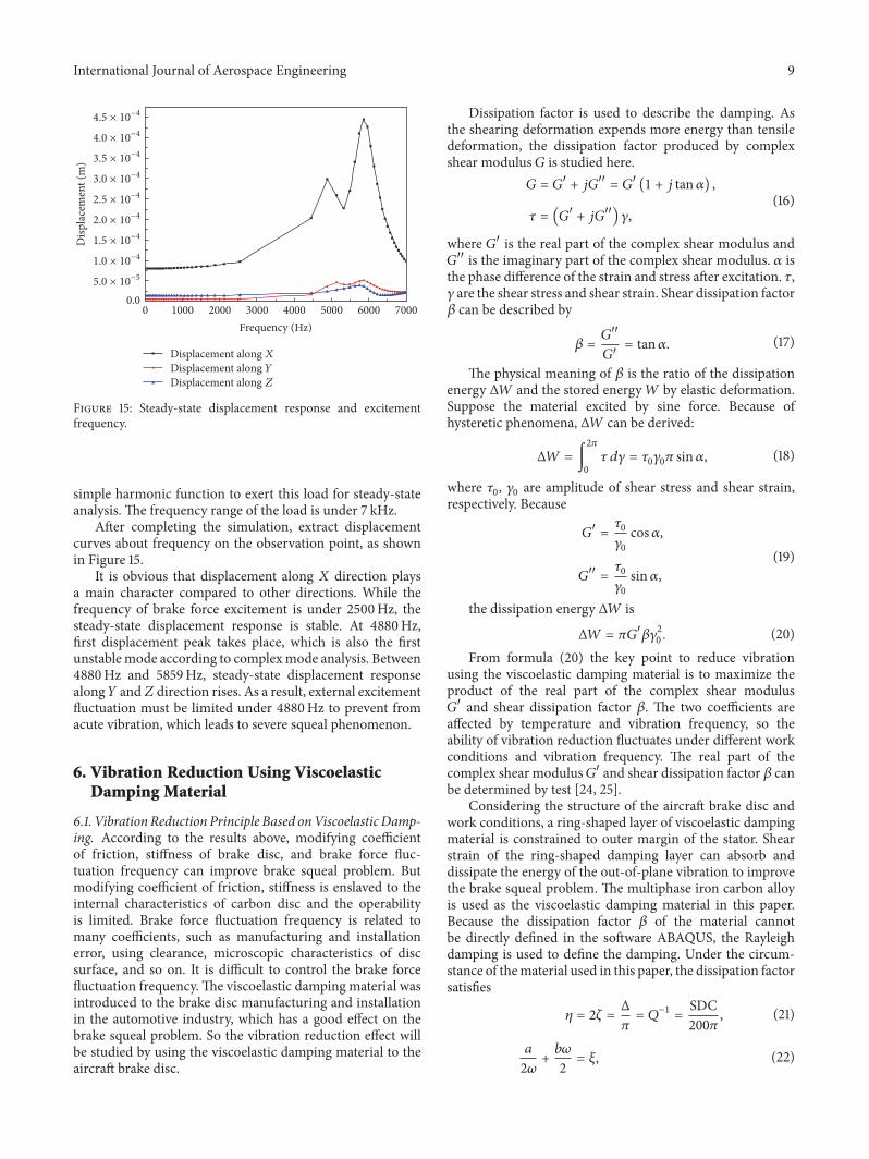