
Analysis of vane loads and motion in a hydraulic double ...
15
Vol.:(0123456789) 1 3 Archives of Civil and Mechanical Engineering (2021) 21:112 https://doi.org/10.1007/s43452-021-00254-y ORIGINAL ARTICLE Analysis of vane loads and motion in a hydraulic double vane pump with integrated electrical drive Wiesław Fiebig 1 · Piotr Cependa 1 · Hubert Kuczwara 1 · Feng Wang 2 Received: 29 January 2021 / Revised: 18 May 2021 / Accepted: 4 June 2021 / Published online: 9 July 2021 © The Author(s) 2021 Abstract In this paper, the results of the analysis of the forces acting on vanes in a double-acting vane pump with an integrated elec- tric drive have been presented. In the new motor pump unit, the pump is assembled inside the rotor of the electric motor. A dynamic model representing the vane movement has been developed considering the impact of pressure load distribution, vane support forces and friction forces. The loss of contact between the vane head and the cam ring lead to the noise and reduction of the volumetric pump efficiency. The dynamic model which describes the vane motion and contact between the vane tip and cam ring has been solved using MATLAB software. The influence of load distribution, pump design and operational parameters on the vane dynamics has been analysed. Keywords Vane pump · Dynamic loads · Vane motion · Internal leakages · Integrated electric drive List of symbols A D Flow surface through the kidneys F pr Pressure force acting on the right side of vane’s head F pl Pressure force acting on the left side of vane’s head F u Vane supporting force from pressure F s Vane supporting force from springs F b Inertia force F p Resultant pressure force along the vane axis F n Reaction force between vane tip and cam ring F h Pressure force acting on the vane head N 1 , N 2 Reaction forces between vane and rotor Q b Flow rate through the channel connecting vane chamber with pressure or the suction area S Contact area between object and fluid T Sum of all friction forces acting along vane axis T f Sum of friction forces in rotor grooves T v Total viscous friction force V c Chamber volume a l Vane thickness affected by the pressure on its left side b v Vane width c vc Damping coefficient between the vane tip and cam ring c v Damping coefficient from oil in the vane chamber c u Damping coefficient from oil under the vane h Lubrication gap thickness/distance between the vane and the cam ring, h = y c − y h h va Axial gap between the vane and pressure plate h vr Radial gap between the vane tip and cam ring h vrg Gap between the vane and rotor groove k vc Spring coefficient between the vane tip and cam ring k s Equivalent spring coefficient of vane support springs l v Vane height l vrg Vane height in the rotor groove l b Length of the channel connecting the vane cham- ber with pressure or the suction area p s Suction pressure p d Delivery pressure p l Pressure on the left side of the vane p r Pressure on the right side of the vane p u Pressure under the vane (vane chamber) Δp b Pressure drop in the channel connecting vane chamber with pressure or the suction area * Wiesław Fiebig wieslaw.fi[email protected] 1 Faculty of Mechanical Engineering, Wroclaw University of Science and Technology, Łukasiewicza 7/9, 50-371 Wrocław, Poland 2 State Key Laboratory of Fluid Power and Mechatronic Systems, School of Mechanical Engineering, Zhejiang University, Hangzhou, China
Transcript of Analysis of vane loads and motion in a hydraulic double ...
Vol.:(0123456789)1 3
Archives of Civil and Mechanical Engineering (2021) 21:112 https://doi.org/10.1007/s43452-021-00254-y
ORIGINAL ARTICLE
Analysis of vane loads and motion in a hydraulic double vane pump with integrated electrical drive
Wiesław Fiebig1 · Piotr Cependa1 · Hubert Kuczwara1 · Feng Wang2
Received: 29 January 2021 / Revised: 18 May 2021 / Accepted: 4 June 2021 / Published online: 9 July 2021 © The Author(s) 2021
AbstractIn this paper, the results of the analysis of the forces acting on vanes in a double-acting vane pump with an integrated elec-tric drive have been presented. In the new motor pump unit, the pump is assembled inside the rotor of the electric motor. A dynamic model representing the vane movement has been developed considering the impact of pressure load distribution, vane support forces and friction forces. The loss of contact between the vane head and the cam ring lead to the noise and reduction of the volumetric pump efficiency. The dynamic model which describes the vane motion and contact between the vane tip and cam ring has been solved using MATLAB software. The influence of load distribution, pump design and operational parameters on the vane dynamics has been analysed.
Keywords Vane pump · Dynamic loads · Vane motion · Internal leakages · Integrated electric drive
List of symbolsAD Flow surface through the kidneysFpr Pressure force acting on the right side of vane’s
headFpl Pressure force acting on the left side of vane’s
headFu Vane supporting force from pressureFs Vane supporting force from springsFb Inertia forceFp Resultant pressure force along the vane axisFn Reaction force between vane tip and cam ringFh Pressure force acting on the vane headN1,N2 Reaction forces between vane and rotorQb Flow rate through the channel connecting vane
chamber with pressure or the suction areaS Contact area between object and fluidT Sum of all friction forces acting along vane axisTf Sum of friction forces in rotor groovesTv Total viscous friction force
Vc Chamber volumeal Vane thickness affected by the pressure on its left
sidebv Vane widthcvc Damping coefficient between the vane tip and
cam ringcv Damping coefficient from oil in the vane chambercu Damping coefficient from oil under the vaneh Lubrication gap thickness/distance between the
vane and the cam ring, h = yc − yhhva Axial gap between the vane and pressure platehvr Radial gap between the vane tip and cam ringhvrg Gap between the vane and rotor groovekvc Spring coefficient between the vane tip and cam
ringks Equivalent spring coefficient of vane support
springslv Vane heightlvrg Vane height in the rotor groovelb Length of the channel connecting the vane cham-
ber with pressure or the suction areaps Suction pressurepd Delivery pressurepl Pressure on the left side of the vanepr Pressure on the right side of the vanepu Pressure under the vane (vane chamber)Δpb Pressure drop in the channel connecting vane
chamber with pressure or the suction area
* Wiesław Fiebig [email protected]
1 Faculty of Mechanical Engineering, Wroclaw University of Science and Technology, Łukasiewicza 7/9, 50-371 Wrocław, Poland
2 State Key Laboratory of Fluid Power and Mechatronic Systems, School of Mechanical Engineering, Zhejiang University, Hangzhou, China
Archives of Civil and Mechanical Engineering (2021) 21:112
1 3
112 Page 2 of 15
rv Curvature radius of the vanerb Radius of the channel connecting vane chamber
with pressure or the suction areasv Vane thicknessU Circumferential speed of the vane relative to the
cam ringyh Vane extension above the rotor circumferenceyc Curvature radius of the cam ring�D Flow coefficient�e Reaction force angle� sv
bv Relationship
�r Friction coefficient between the vane and rotor�f Compressibility factor of the fluid�c Friction coefficient between the vane tip and cam
ring� Dynamic oil viscosity
1 Introduction
The new design of the vane pump integrated with the electric motor [1] is based on the kinematic inversion and assumes that the rotor of the electric motor is the outer casing of the pump. Since the pump shaft and motor shaft are not connected, the drive torque is transmitted due to the form-fit connection between the rotor of the electric motor and the pump cam ring. Both elements are fixed together. The principle of operation of the pump significantly differs from standard pumps because the cam ring rotates with the rotor of the electric motor, while the pump “rotor” and the vanes placed in it remain stationary. There is no centrifugal force that press the vanes against the cam ring. In the new design, the vane supporting force comes from the springs located under the vanes and from the operating pressure of the pump acting on the bottom surface of the vanes.
There are many papers on the friction between the vane tip and cam ring. Inaguma [2–4] shows that this type of fric-tion has a significant impact on the mechanical efficiency of a double-acting vane pump and that the friction force is proportional to the vane force, vane thickness and deliv-ery pressure. Elashmawy [5, 6] stated that the oil type used by the vane pump is an essential element influencing the pump performance. Faber and Ortwig [7, 8] have carried out the experimental and theoretical investigations of fric-tion between vanes and cam ring and developed theoretical model for the description of vane friction. Wasel at all in [9] developed a (Thermo-Elasto-Hydrodynamic Lubrica-tion) TEHL-Model was developed to calculate the friction forces between vane tip and cam ring in oil vane pumps. The results showed in [10] show that the lubrication mode of the vane tip exists in the rigid-variable-viscosity region, and that discharge pressure affects the oil film pressure. Mucchi
[11] proposed a methodology for the identification of the lubrication which occurs between the vane and cam ring and analyse the wear occurring on the vane tip. Almghadi [12] investigated the influence of the vane tip geometry on the lubrication conditions. Frendo [13], Rundo [14] and Suzuki [15] describe models for determining the pressure loads in a vane pump as well as CFD 3D models for the flow simulation.
There are a few papers focussed on the vane dynamics. One model for the description of vane motion for single act-ing vane pumps have been presented in the paper [16, 17] published in 1990 and 1992. The losing of contact between the vane and cam ring is caused due to the pressure overdue in the inter-vane volumes. The results of simulation have been compared with the experimental results. Myung-Rae Cho [18] presented the numerical model for the simulation of vane motion and vane chamber pressure changes. It has also been stated that the vane detachment occurs due to the excess pressure in the inter-vane chambers.
This paper describes the forces acting on the vanes in a new design of the vane pump with an integrated elec-tric drive which is important for the description of vane motion. The first part describes the design principle of the pump. Then, the forces acting on the vane and the pressure courses occurring in the inter-vane volumes are described. A dynamic model of a vane was developed, taking into account the frictional and damping forces which have a significant impact on its movement. The final part describes the results of experimental studies confirming the results obtained on the basis of the model.
2 Design of the motor pump assembly
In the new solution (Fig. 1), the hydraulic pump is built into the rotor of the electric motor with permanent magnets (BLDC—Brushless Direct Current). The rotor of the electric motor causes the rotation of the pump housing. The internal part of the pump with the vanes is not movable. Due to lack of rotation, the vanes are pressed against a cam ring with spring elements.
Double vane pumps have many advantages, such as load compensation, small reaction forces in the bearings and rela-tively high efficiency. These pumps are also often applied due to their high durability and simple design and manufac-turing [1, 5–7].
Figure 1 shows a cross-section of a double-acting vane pump integrated in the rotor of an electric motor [1] with permanent magnets. A BLDC motor has been used because such motors have the highest energy efficiency, the highest power value per unit mass, large durability and a very good dynamic range.

Archives of Civil and Mechanical Engineering (2021) 21:112
1 3
Page 3 of 15 112
In Fig. 2, the pump elements 1, 2, and 4 are movable while the elements 3, 5, and 6 are stationary. The connec-tion to the suction and delivery line occurs with the pres-sure compensated plate 5 and the connecting part 6 with the suction and discharge channels. Several problems had to be overcome through the different stages of the design process. One of the important issues was to select the geometry of the cross over areas between the suction and discharge ports and to provide sufficient support for the vanes in these areas.
To avoid the magnetisation of the fluid inside the pump and the collection of metallic impurities particles, the non-magnetic sleeve 6 (Fig. 1) has been used. This solution can be used in applications in which the high power, high compactness and low noise of the fluid power drives are required. The possibility to control the flow of the displace-ment pumps directly through the rotational speed has many advantages and is an important simplification of fluid power drives.
The solution has all advantages of the Variable Speed Drives (VSD) where the electric drive with variable rpm and hydraulic pump with constant displacement are combined. Due to the adjustment of the power of the electric motor
to the power required from actuators (hydraulic cylinder or hydraulic motor), higher efficiency can be achieved. In the new solution, an additional up to 40% mass reduction in comparison with the conventional assembly can be obtained and lower noise emission is to be expected due to the loca-tion of the pump inside the electric motor. The features such as high power density, robustness and simple realisation of fast linear movements under load are very important in com-petition with electromechanical servo drives.
This solution can be used especially in key market seg-ments such as plastic machinery, stamping and forming presses, metallurgy, aircraft industry, testing machinery and many other applications.
3 Forces acting on the vane
3.1 Simulation of the pressure in the inter‑vane volume
In Fig. 3, the flow balance in the inter-vane volume has been shown [20]. The flows and leakages between the inter-vane chamber n and adjacent chambers n − 1 and n + 1 can be divided into:
Qan is the leakage in the sum of the flows through axial gap,Qrn is the leakages through the radial gap,Qrg is the leakages through the rotor grooves,Qs is the flow through the kidneys.
The calculation of the pressure and flow changes in the chamber between the vanes starts with the determination of the chamber volume and its changes in time [19–21]. To establish the pressure change in the inter-vane volume Qn the
Fig. 1 Vane pump integrated with BLDC motor—cross-section [1]. 1—stator, 2—pump cartridge, 3—suction and delivery channels, 4—pump rotor, 5—rotor of BLDC motor, 6—nonmagnetic sleeve, 7—permanent magnets, 8—external housing
Fig. 2 Vane pump module [1]. 1—left pressure plate, 2—cam ring, 3—pump rotor, 4—right pressure plate/rotational part of flow distrib-utor, 5—stationary part of flow distributor, 6—delivery channels Fig. 3 Flow balance inside the chamber between the vanes
Archives of Civil and Mechanical Engineering (2021) 21:112
1 3
112 Page 4 of 15
balance of the incoming and outgoing flow rates should be taken into account [1]:
where ∑
Qan is the sum of the flows through axial gaps, ∑Qrn is the sum of the flows through the radial gaps,
∑Qs
is the flow through the kidneys, ∑
Qrg is the flow through the rotor grooves, Qn is the change of the chamber volume over time.
A laminar flow through an axial gap hva is assumed in accordance with the following formula:
where Δpn is the pressure difference between the inter-vane chamber n and adjacent chambers.
The flow in the radial gap can be described with
(1)
dp
dt=
1
�fVn
(Qn −
∑Qan −
∑Qrn −
∑Qrg −
∑Qs
),
(2)Qan =lv ⋅ h
3vaΔpn
12 ⋅ � ⋅ sv,
The flow in the gap between the vane and rotor groove can be described with (Fig. 3)
The flow through the suction and delivery kidneys:
The leakages and the pressure calculations have been per-formed in the AMESim Software [20].
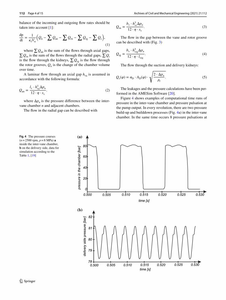
Figure 4 shows examples of computational time runs of pressure in the inter-vane chamber and pressure pulsation at the pump output. In every revolution, there are two pressure build-up and builddown processes (Fig. 4a) in the inter-vane chamber. In the same time occurs 8 pressure pulsations at
(3)Qrn =bv ⋅ h
3vrΔpn
12 ⋅ � ⋅ sv.
(4)Qrg =bv ⋅ h
3vrgΔpn
12 ⋅ � ⋅ lvrg.
(5)Qs(�) = �D ⋅ AD(�) ⋅
√2 ⋅ Δpn
�f.
Fig. 4 The pressure courses (n = 2500 rpm, p = 8 MPa) a inside the inter-vane chamber, b on the delivery side, data for simulation according to the Table 1, [19]

Archives of Civil and Mechanical Engineering (2021) 21:112
1 3
Page 5 of 15 112
the pump output (Fig. 4b), because the experimental pump has 8 vanes.
3.2 Pressure forces on the vane
Pressure forces acting on the vane cause reaction forces in contact between the vane, cam ring and rotor. As the vane moves in the radial direction, relative to the rotor, friction forces arise at the point of contact. Figure 5 shows the forces acting on the vane.
During pump operation, it is very important that the vane and cam ring are in contact. Each detachment of the vane head from the cam ring results in the connection of adja-cent displacement chambers of the pump and a decrease of its volume efficiency. Adequate pressure below the vane ensures sufficient support to keep the vane tip in contact with the cam ring surface. The main forces acting on the vane are forces from the pressure, which depends on the pressure in the displacement chambers of the pump. If the vane sepa-rates two displacement chambers at different pressures, the distribution of forces from the pressure is uneven and causes the vane tilting in the rotor grooves.
The characteristic positions of the vanes in relation to the cam ring are shown in Fig. 6, and corresponding to them, the distribution of pressure on the vanes is shown in Fig. 7.
Fig. 5 Forces acting on the vane
Fig. 6 Vanes position in relation to the cam ring
Fig. 7 Pressure distribution on vanes for different positions in relation to the cam ring
Archives of Civil and Mechanical Engineering (2021) 21:112
1 3
112 Page 6 of 15
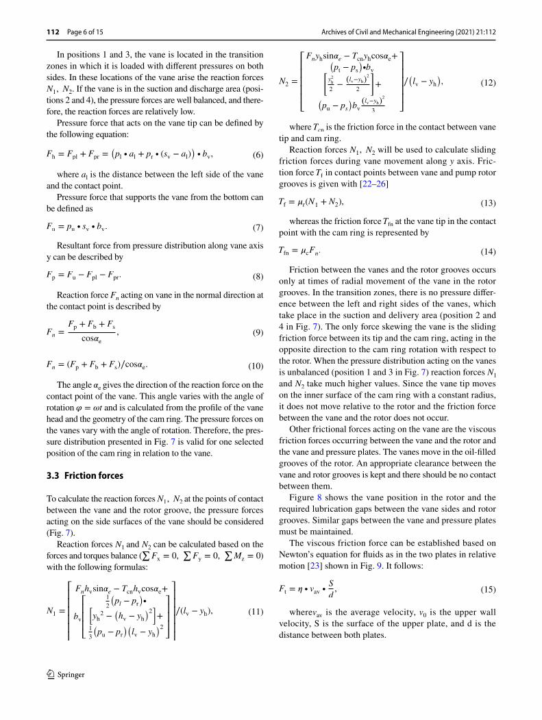
In positions 1 and 3, the vane is located in the transition zones in which it is loaded with different pressures on both sides. In these locations of the vane arise the reaction forces N1, N2 . If the vane is in the suction and discharge area (posi-tions 2 and 4), the pressure forces are well balanced, and there-fore, the reaction forces are relatively low.
Pressure force that acts on the vane tip can be defined by the following equation:
where al is the distance between the left side of the vane and the contact point.
Pressure force that supports the vane from the bottom can be defined as
Resultant force from pressure distribution along vane axis y can be described by
Reaction force Fn acting on vane in the normal direction at the contact point is described by
The angle �e gives the direction of the reaction force on the contact point of the vane. This angle varies with the angle of rotation � = �t and is calculated from the profile of the vane head and the geometry of the cam ring. The pressure forces on the vanes vary with the angle of rotation. Therefore, the pres-sure distribution presented in Fig. 7 is valid for one selected position of the cam ring in relation to the vane.
3.3 Friction forces
To calculate the reaction forces N1, N2 at the points of contact between the vane and the rotor groove, the pressure forces acting on the side surfaces of the vane should be considered (Fig. 7).
Reaction forces N1 and N2 can be calculated based on the forces and torques balance (
∑Fx = 0,
∑Fy = 0,
∑Mz = 0 )
with the following formulas:
(6)Fh = Fpl + Fpr =(pl ∙ al + pr ∙ (sv − al)
)∙ bv,
(7)Fu = pu ∙ sv ∙ bv.
(8)Fp = Fu − Fpl − Fpr.
(9)Fn =Fp + Fb + Fs
cos�e,
(10)Fn = (Fp + Fb + Fs)∕cos�e.
(11)N1 =
⎡⎢⎢⎢⎢⎢⎣
Fnhvsin�e − Tcnhvcos�e+
bv
⎡⎢⎢⎢⎣
1
2
�pl − pr
�∙�
yh2 −
�hv − yh
�2�+
1
3
�pu − pr
��lv − yh
�2
⎤⎥⎥⎥⎦
⎤⎥⎥⎥⎥⎥⎦
∕(lv − yh),
where Tcn is the friction force in the contact between vane tip and cam ring.
Reaction forces N1, N2 will be used to calculate sliding friction forces during vane movement along y axis. Fric-tion force Tf in contact points between vane and pump rotor grooves is given with [22–26]
whereas the friction force Tfn at the vane tip in the contact point with the cam ring is represented by
Friction between the vanes and the rotor grooves occurs only at times of radial movement of the vane in the rotor grooves. In the transition zones, there is no pressure differ-ence between the left and right sides of the vanes, which take place in the suction and delivery area (position 2 and 4 in Fig. 7). The only force skewing the vane is the sliding friction force between its tip and the cam ring, acting in the opposite direction to the cam ring rotation with respect to the rotor. When the pressure distribution acting on the vanes is unbalanced (position 1 and 3 in Fig. 7) reaction forces N1 and N2 take much higher values. Since the vane tip moves on the inner surface of the cam ring with a constant radius, it does not move relative to the rotor and the friction force between the vane and the rotor does not occur.
Other frictional forces acting on the vane are the viscous friction forces occurring between the vane and the rotor and the vane and pressure plates. The vanes move in the oil-filled grooves of the rotor. An appropriate clearance between the vane and rotor grooves is kept and there should be no contact between them.
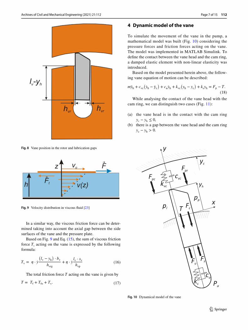
Figure 8 shows the vane position in the rotor and the required lubrication gaps between the vane sides and rotor grooves. Similar gaps between the vane and pressure plates must be maintained.
The viscous friction force can be established based on Newton’s equation for fluids as in the two plates in relative motion [23] shown in Fig. 9. It follows:
wherevav is the average velocity, v0 is the upper wall velocity, S is the surface of the upper plate, and d is the distance between both plates.
(12)N2 =
⎡⎢⎢⎢⎢⎢⎣
Fnyhsin�e − Tcnyhcos�e+�pt − ps
�∙bv�
y2h
2−
(lv−yh)2
2
�+
�pu − ps
�bv
(lv−yh)2
3
⎤⎥⎥⎥⎥⎥⎦
∕�lv − yh
�,
(13)Tf = �r(N1 + N2),
(14)Tfn = �cFn.
(15)Ft = � ∙ vav ∙S
d,
Archives of Civil and Mechanical Engineering (2021) 21:112
1 3
Page 7 of 15 112
In a similar way, the viscous friction force can be deter-mined taking into account the axial gap between the side surfaces of the vane and the pressure plate.
Based on Fig. 9 and Eq. (15), the sum of viscous friction force Tv acting on the vane is expressed by the following formula:
The total friction force T acting on the vane is given by
(16)Tv = 𝜂 ⋅ y
(lv − yh
)⋅ bv
hvrg+ 𝜂 ⋅ y
lv ⋅ sv
hvp
(17)T = Tf + Tfn + Tv.
4 Dynamic model of the vane
To simulate the movement of the vane in the pump, a mathematical model was built (Fig. 10) considering the pressure forces and friction forces acting on the vane. The model was implemented in MATLAB Simulink. To define the contact between the vane head and the cam ring, a damped elastic element with non-linear elasticity was introduced.
Based on the model presented herein above, the follow-ing vane equation of motion can be described:
While analysing the contact of the vane head with the cam ring, we can distinguish two cases (Fig. 11):
(a) the vane head is in the contact with the cam ring yc − yh ≤ 0,
(b) there is a gap between the vane head and the cam ring yc − yh > 0.
(18)myh + cvc
(yh − yc
)+ cuyh + kvc
(yh − yc
)+ ksyh = Fp − T .
Fig. 8 Vane position in the rotor and lubrication gaps
Fig. 9 Velocity distribution in viscous fluid [23]
Fig. 10 Dynamical model of the vane

Archives of Civil and Mechanical Engineering (2021) 21:112
1 3
112 Page 8 of 15
In the situation when the vane head is in contact with the cam ring and there is no oil film between them, the model assumes a linear contact of both surfaces, considering Hertz-ian contact. The stiffness coefficient for the spring element between the vane head and cam ring will be described as [26]
In the second case, the gap between the vane head and the cam ring is small enough to create a thin oil film. Since the cam ring moves with high speeds against the vanes, a hydrodynamic force is created towards the centre of the rotor. The generalised Reynolds equation [24, 27] can be used to calculate the pressure distribution on the vane head:
where h is the local oil film thickness, p is the local oil film pressure, x is the circumferential direction, y is the lon-gitudinal direction, U is the linear vane velocity, and � is the dynamic viscosity of oil.
The hydrodynamic force between the vane head and cam ring can be described with the following formula [24]:
where rv is the radius of the curvature on the vane tip and hvcmin is the minimum value of the gap between the vane tip and cam ring.
(19)kvc =2rvbv
0.462⋅ 107
[N
m
].
(20)�
�x
(h3 ∙
�p
�x
)+
�
�y
(h3 ∙
�p
�y
)= 6U�
�h
�x,
(21)Fhd =2.45 ∙ U ∙ � ∙ bv ∙ rv
hvcmin
,
For higher gap values, the flow over the vane head and the pressure distribution can be determined by CFD analysis [1, 19].
The change of the oil volume pumped in or out of the chamber below the vane is equal to the flow rate through the connecting channel. Based on the sketch shown in Fig. 12, the damping force results from the pressure drop in the chan-nel connecting the vane chamber with the suction and dis-charge spaces.
Fig. 11 Vane contact with the cam ring
Fig. 12 Under vane chamber
Archives of Civil and Mechanical Engineering (2021) 21:112
1 3
Page 9 of 15 112
Assuming laminar flow from the under vane chamber to pressure or suction chamber, the damping force due to the pressure drop along the length lb is represented by the fol-lowing formula [17]:
The damping factor will be
Equation (23) shows that the damping force increases with increasing pump speed. Its value is inversely propor-tional to the cross-section of the channel connecting the vane chamber with the suction and discharge spaces of the pump. The description does not include oil inertia forces and flow phenomena in the pump suction chamber.
The occurrence of an oil film between two interacting surfaces creates a damping effect when the two surfaces approach each other. This is because the gap between them decreases, while the oil must be squeezed out between both surfaces. This phenomenon is referred to as “squeeze film damping”. For two flat rectangular surfaces, the damping coefficient takes the form [17]:
where � = sv∕bvef and bvef is the effective thickness on the vane tip.
Since the vane tip is rounded, its effective gap width bvef is very small thus the damping coefficient is also small. It is also to mention that the squeeze film damping coefficient cvc is strongly dependent on the vane width.
5 Simulation results
For the simulation, the parameters used have been shown in Table 1.
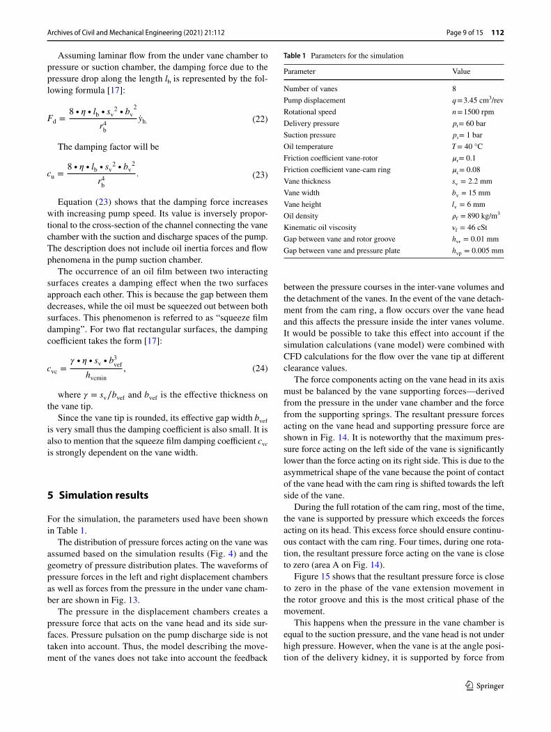
The distribution of pressure forces acting on the vane was assumed based on the simulation results (Fig. 4) and the geometry of pressure distribution plates. The waveforms of pressure forces in the left and right displacement chambers as well as forces from the pressure in the under vane cham-ber are shown in Fig. 13.
The pressure in the displacement chambers creates a pressure force that acts on the vane head and its side sur-faces. Pressure pulsation on the pump discharge side is not taken into account. Thus, the model describing the move-ment of the vanes does not take into account the feedback
(22)Fd =8 ∙ 𝜂 ∙ lb ∙ sv
2 ∙ bv2
r4b
yh.
(23)cu =8 ∙ � ∙ lb ∙ sv
2 ∙ bv2
r4b
.
(24)cvc =� ∙ � ∙ sv ∙ b
3vef
hvcmin
,
between the pressure courses in the inter-vane volumes and the detachment of the vanes. In the event of the vane detach-ment from the cam ring, a flow occurs over the vane head and this affects the pressure inside the inter vanes volume. It would be possible to take this effect into account if the simulation calculations (vane model) were combined with CFD calculations for the flow over the vane tip at different clearance values.
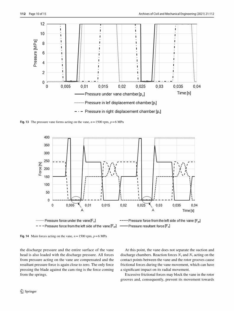
The force components acting on the vane head in its axis must be balanced by the vane supporting forces—derived from the pressure in the under vane chamber and the force from the supporting springs. The resultant pressure forces acting on the vane head and supporting pressure force are shown in Fig. 14. It is noteworthy that the maximum pres-sure force acting on the left side of the vane is significantly lower than the force acting on its right side. This is due to the asymmetrical shape of the vane because the point of contact of the vane head with the cam ring is shifted towards the left side of the vane.
During the full rotation of the cam ring, most of the time, the vane is supported by pressure which exceeds the forces acting on its head. This excess force should ensure continu-ous contact with the cam ring. Four times, during one rota-tion, the resultant pressure force acting on the vane is close to zero (area A on Fig. 14).
Figure 15 shows that the resultant pressure force is close to zero in the phase of the vane extension movement in the rotor groove and this is the most critical phase of the movement.
This happens when the pressure in the vane chamber is equal to the suction pressure, and the vane head is not under high pressure. However, when the vane is at the angle posi-tion of the delivery kidney, it is supported by force from
Table 1 Parameters for the simulation
Parameter Value
Number of vanes 8Pump displacement q = 3.45 cm3/revRotational speed n = 1500 rpmDelivery pressure pt = 60 barSuction pressure ps = 1 barOil temperature T = 40 °CFriction coefficient vane-rotor �r = 0.1Friction coefficient vane-cam ring �c = 0.08Vane thickness sv = 2.2 mm
Vane width bv = 15 mmVane height lv = 6 mm
Oil density �f = 890 kg/m3
Kinematic oil viscosity �f = 46 cSt
Gap between vane and rotor groove hvr = 0.01 mm
Gap between vane and pressure plate hvp = 0.005 mm
Archives of Civil and Mechanical Engineering (2021) 21:112
1 3
112 Page 10 of 15
the discharge pressure and the entire surface of the vane head is also loaded with the discharge pressure. All forces from pressure acting on the vane are compensated and the resultant pressure force is again close to zero. The only force pressing the blade against the cam ring is the force coming from the springs.
At this point, the vane does not separate the suction and discharge chambers. Reaction forces N1 and N2 acting on the contact points between the vane and the rotor grooves cause frictional forces during the vane movement, which can have a significant impact on its radial movement.
Excessive frictional forces may block the vane in the rotor grooves and, consequently, prevent its movement towards
Fig. 13 The pressure vane forms acting on the vane, n = 1500 rpm, p = 6 MPa
Fig. 14 Main forces acting on the vane, n = 1500 rpm, p = 6 MPa
Archives of Civil and Mechanical Engineering (2021) 21:112
1 3
Page 11 of 15 112
the cam ring. The analysis of the pump design shows that the N1 and N2 forces are greatest at the times when the vane separates two displacement chambers at different pressures. The hydrostatic pressure forces acting on the side surfaces of the vane are then unbalanced and the vane is “tilted” in the rotor seat.
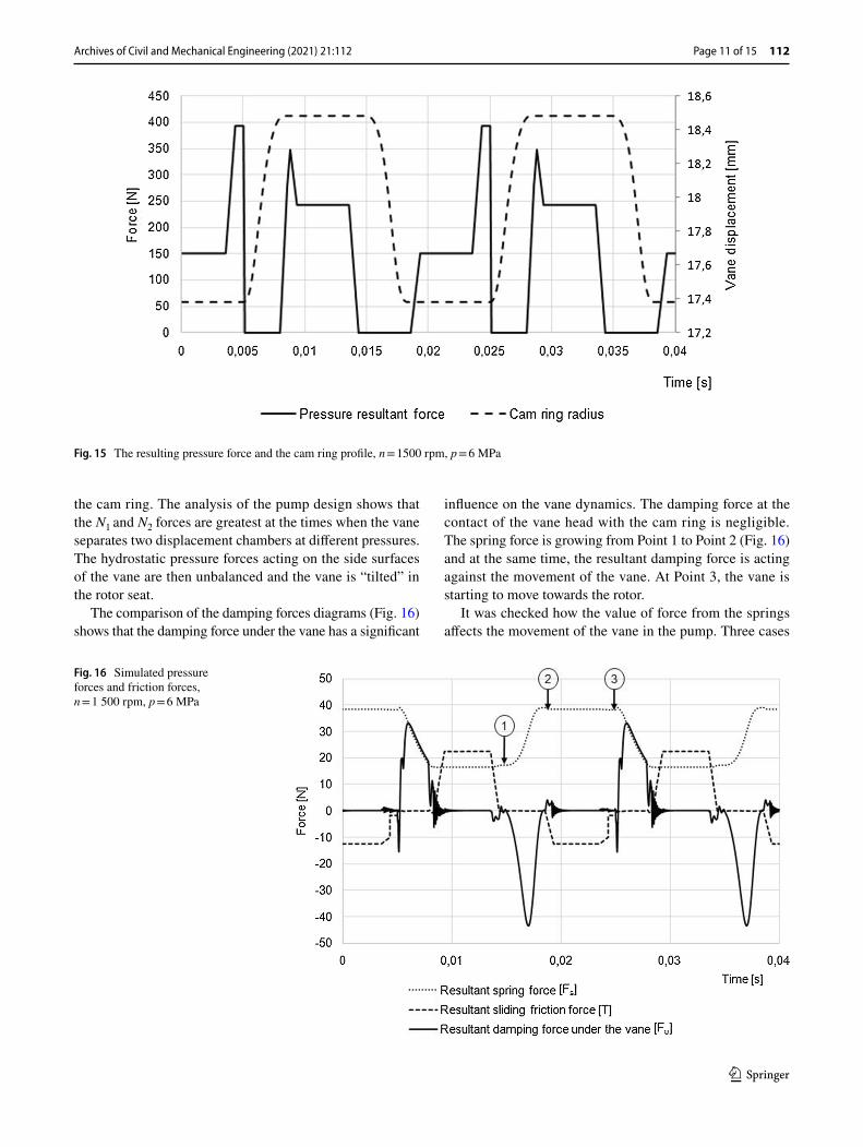
The comparison of the damping forces diagrams (Fig. 16) shows that the damping force under the vane has a significant
influence on the vane dynamics. The damping force at the contact of the vane head with the cam ring is negligible. The spring force is growing from Point 1 to Point 2 (Fig. 16) and at the same time, the resultant damping force is acting against the movement of the vane. At Point 3, the vane is starting to move towards the rotor.
It was checked how the value of force from the springs affects the movement of the vane in the pump. Three cases
Fig. 15 The resulting pressure force and the cam ring profile, n = 1500 rpm, p = 6 MPa
Fig. 16 Simulated pressure forces and friction forces, n = 1 500 rpm, p = 6 MPa
Archives of Civil and Mechanical Engineering (2021) 21:112
1 3
112 Page 12 of 15
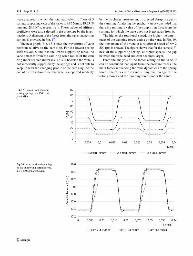
were analysed in which the total equivalent stiffness of 5 springs supporting each of the vanes is 9.85 N/mm, 19.33 N/mm and 28.4 N/m, respectively. These values of stiffness coefficient were also selected in the prototype by the inves-tigations. A diagram of the forces from the vanes supporting springs is provided in Fig. 17.
The next graph (Fig. 18) shows the waveforms of vane position relative to the cam ring. For the lowest spring stiffness value, and thus the lowest supporting force, the vane detaches from the cam ring when radius of the cam ring inner surface increases. This is because the vane is not sufficiently supported by the springs and is not able to keep up with the changing profile of the cam ring. At the end of the transition zone, the vane is supported suddenly
by the discharge pressure and is pressed abruptly against the cam ring. Analysing the graph, it can be concluded that there is a minimum value of the supporting force from the springs, for which the vane does not break away from it.
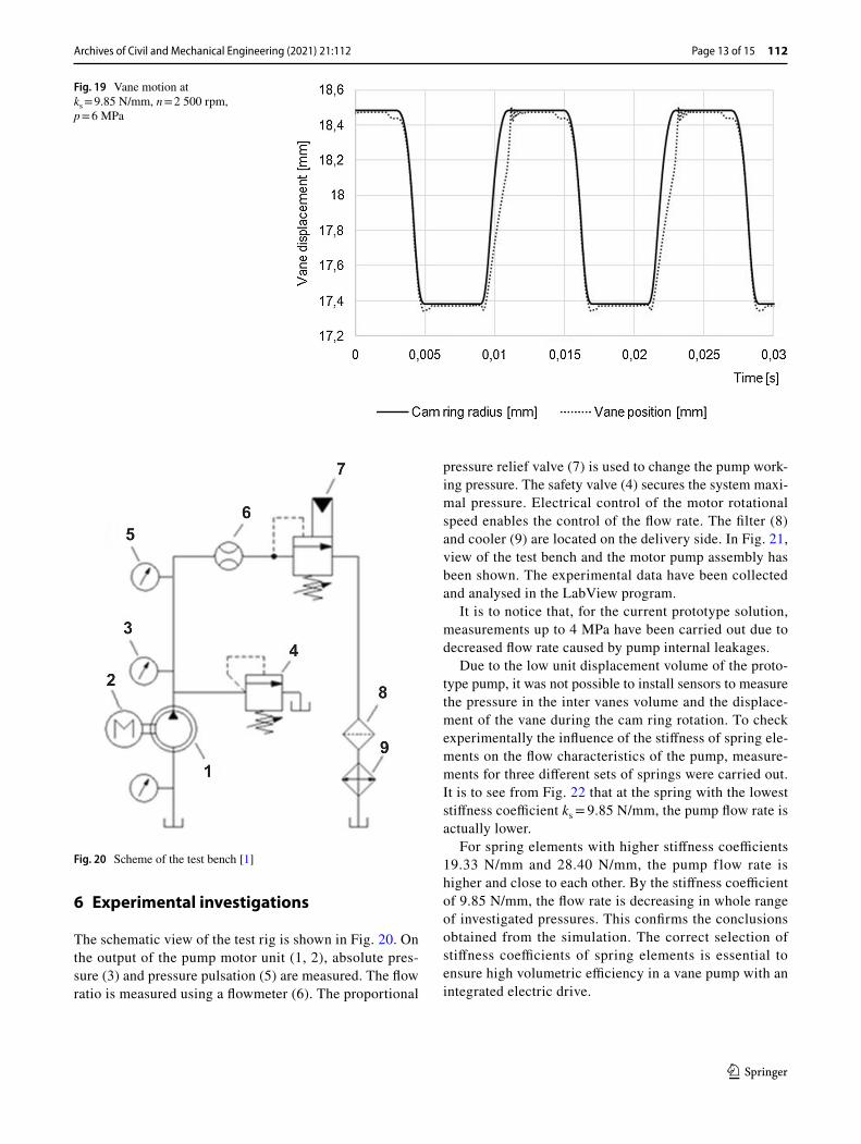
The higher the rotational speed, the higher the ampli-tudes of the damping forces acting on the vane. In Fig. 19, the movement of the vane at a rotational speed of n = 2 500 rpm is shown. The figure shows that for the same stiff-ness of the supporting springs at higher speeds, the gap between the vane head and cam becomes larger.
From the analysis of the forces acting on the vane, it can be concluded that, apart from the pressure forces, the main forces influencing the vane dynamics are the spring forces, the forces of the vane sliding friction against the rotor grooves and the damping forces under the vane.
Fig. 17 Forces from vane sup-porting springs, n = 1500 rpm, p = 6 MPa
Fig. 18 Vane motion depending on the supporting spring forces, n = 1 500 rpm, p = 6 MPa
Archives of Civil and Mechanical Engineering (2021) 21:112
1 3
Page 13 of 15 112
6 Experimental investigations
The schematic view of the test rig is shown in Fig. 20. On the output of the pump motor unit (1, 2), absolute pres-sure (3) and pressure pulsation (5) are measured. The flow ratio is measured using a flowmeter (6). The proportional
pressure relief valve (7) is used to change the pump work-ing pressure. The safety valve (4) secures the system maxi-mal pressure. Electrical control of the motor rotational speed enables the control of the flow rate. The filter (8) and cooler (9) are located on the delivery side. In Fig. 21, view of the test bench and the motor pump assembly has been shown. The experimental data have been collected and analysed in the LabView program.
It is to notice that, for the current prototype solution, measurements up to 4 MPa have been carried out due to decreased flow rate caused by pump internal leakages.
Due to the low unit displacement volume of the proto-type pump, it was not possible to install sensors to measure the pressure in the inter vanes volume and the displace-ment of the vane during the cam ring rotation. To check experimentally the influence of the stiffness of spring ele-ments on the flow characteristics of the pump, measure-ments for three different sets of springs were carried out. It is to see from Fig. 22 that at the spring with the lowest stiffness coefficient ks = 9.85 N/mm, the pump flow rate is actually lower.
For spring elements with higher stiffness coefficients 19.33 N/mm and 28.40 N/mm, the pump flow rate is higher and close to each other. By the stiffness coefficient of 9.85 N/mm, the flow rate is decreasing in whole range of investigated pressures. This confirms the conclusions obtained from the simulation. The correct selection of stiffness coefficients of spring elements is essential to ensure high volumetric efficiency in a vane pump with an integrated electric drive.
Fig. 19 Vane motion at ks = 9.85 N/mm, n = 2 500 rpm, p = 6 MPa
Fig. 20 Scheme of the test bench [1]

Archives of Civil and Mechanical Engineering (2021) 21:112
1 3
112 Page 14 of 15
7 Conclusions
In this paper, the results of theoretical studies on vane loads and their dynamic behaviour in a double-acting vane pump with an integrated electric drive have been presented. A dynamical model for the determination of vane motion was developed, with the help of which it is possible to determine the causes of vane detachment from the cam ring. From the analysis, it follows that the unde-sired vane detachment occurs due to hydraulic processes
and both pressure and friction forces. The pressure forces at the vane head and the spring and damping forces in the space under the vanes determine the extent of lifting in the suction area.
Despite many simplifying assumptions made during the model development, the results obtained on the basis of the simulation allow to explain the cause–effect relationships causing the vanes detachment from the cam ring. With the knowledge gained, measures can be derived to prevent the vane from lifting off the cam ring. As a result, an improve-ment in volumetric efficiency of the vane pump with the
Fig. 21 Test bench: a view b motor pump assembly
Fig. 22 Flow rate of the pump depending on the supporting spring forces, n = 1500 rpm
Archives of Civil and Mechanical Engineering (2021) 21:112
1 3
Page 15 of 15 112
integrated electric drive has been achieved. In further research, it is planned to expand the model by calculating the pressure courses in each inter-vane volume and taking into account the feedback between pressure courses in inter-vane volumes and vane movements. In addition, more effort by including contact conditions between the vane tip and cam ring in the model is needed, especially for high-pressure applications.
Funding This study was funded by The Polish National Centre of Research and Development (NCBR), Grant No. 208471.
Declarations
Conflict of interest The authors declare that they have no conflict of interest.
Open Access This article is licensed under a Creative Commons Attri-bution 4.0 International License, which permits use, sharing, adapta-tion, distribution and reproduction in any medium or format, as long as you give appropriate credit to the original author(s) and the source, provide a link to the Creative Commons licence, and indicate if changes were made. The images or other third party material in this article are included in the article’s Creative Commons licence, unless indicated otherwise in a credit line to the material. If material is not included in the article’s Creative Commons licence and your intended use is not permitted by statutory regulation or exceeds the permitted use, you will need to obtain permission directly from the copyright holder. To view a copy of this licence, visit http:// creat iveco mmons. org/ licen ses/ by/4. 0/.
References
1. Fiebig W, Cependa P, Jędraszczyk P, Kuczwara H. Innovative solution of an integrated motor pump assembly. ASME Sympo-sium on Fluid Power and Motion Control, Sarasota, FL, USA (2017)
2. Inaguma Y. Theoretical analysis of mechanical efficiency in vane pump. JTEKT Eng J Eng Ed. 2010;1007E:28–35.
3. Inaguma Y. Friction characteristics of vane for a balanced vane pump. Jpn Fluid Power Syst Soc. 2014;45(4):58–65.
4. Inaguma Y, Hibi A. Vane pump theory for mechani-cal efficiency. Proc Inst Mech Eng Part C J Mech Eng Sci. 2005;219(11):1269–78.
5. Elashmawy M. Theoretical investigation of friction forces between vane tip and cam-ring in oil vane pumps. Int J Sci Technol Soc. 2014;2(5):121–8.
6. Ashmawy MEL, Murrenhoff H. Experimental investigation of friction force between vane tip and cam-ring in oil vane pumps. Int J Fluid Power. 2009;10(1):37–46.
7. Faber I. Theoretische und experimentelle Untersuchung der Flügelkopfreibung in einer Flügelzellenpumpe. Diss. TU Bochum. 2005
8. Ortwig H. Analytische und experimentelle Untersuchung hochb-elasteter linienförmiger Gleitkontakte in einer Flügelzellenpumpe, Diss. RWTH Aachen. 1990
9. Wasel M, Abdel-Rahim A, El-Gohary H, Elashmawy M. Theo-retical study of the parameters affecting vane tip friction in oil vane pumps using simplified Tehl-model. Int J Sci Technol. 2015;3:60–70.
10. Cho IS, Oh SH, Song KK, et al. The Lubrication characteristics of the vane tip under pressure boundary condition of oil hydraulic vane pump. J Mech Sci Technol. 2006;20(10):1716–21.
11. Mucchi E, Agazzi A, D’Elia G, et al. On the wear and lubri-cation regime in variable displacement vane pumps. Wear. 2013;306(1–2):36–46.
12. Alghamdi A, Elashmawy M. Vane geometry effect on lubrica-tion conditions between vane tip and cam-ring in hydraulic vane machines. Int J Mech Eng Appl. 2014;3(1):1–10.
13. Frendo F, Novi N, Squarcini R. Numerical and experimental analysis of variable displacement vane pumps. International con-ference on tribology. 20–22 September 2006, Parma, Italy. 2006
14. Rundo M., Altare G. (2017). Lumped parameter and three-dimen-sional CFD simulation of a variable displacement vane pump for engine lubrication. Proceedings of the ASME 2017 fluids engi-neering division summer meeting
15. Suzuki K, Nakamura Y, et al. Characteristics Prediction of Vane Pump by CFD Analysis. KYB Tech Rev. 2016;53:8–15.
16. Heisel U, Fiebig W. Betrachtungen zum dynamischen Verhalten von druckgeregelten Fluegelzellenpumpen. Oelhydraulik und Pneumatik. 1990;34(6):429–32.
17. Heisel U, Fiebig W, Matten N. Untersuchungen zum Fluegelver-halten von Druckgeregelten Fluegelzellenpumpen. Oelhydraulik und Pneumatik. 1992;36(2):102–10.
18. Cho MR, Han DC. Vane tip detachment in a positive displacement vane pump. KSME Int J. 1998;12(5):881–7.
19. Fiebig W, Dudzikowski I, Ciurys M, Kuczwara H. A vane pump integrated with an electric motor. The 9th international fluid power conference, 9. IFK, March 24–26, Aachen, Germany. 2014
20. Heisel U, Fiebig W, Matten N. Druckwechselvorgänge in druck-geregelten Flüelzellenpumpen. Oelhydraulik und Pneumatik. 1991;35(12):906–13.
21. Cavallari M. A lumped parameter model for the pressure and vibration analysis of variable displacement vane pumps, Univer-sita degli Studi di Ferrara. 2011
22. Dowson D, Higginson GR. Elasto-hydrodynamic Lubrication. London: Pergamon Press; 1997.
23. Wen S, Huang P, Tian Y, Liran M. Principles of Tribology. 5th ed. Beijing: Tsinghua University Press; 2018.
24. Cameron A (1966) Principles of lubrication. lmgmans Green, London
25. Totten GE. Handbook of lubrication and tribology. In: Application and maintenance, vol. I. Routledge: Taylor and Francis Group; 2006.
26. Eschmann P, Hasbargen L, Weigand K. Waezlager-praxis. Munich: Oldenlmrg-Verlag; 1979.
27. Wei SL, Wang Z, Ji H. Effects of shape of vane on force of vane in high pressure vane pump. Proceedings of the 2011 international conference on fluid power and mechatronics, 2011
Publisher’s Note Springer Nature remains neutral with regard to jurisdictional claims in published maps and institutional affiliations.


![Lecture 8 HYDRAULIC PUMPS [CONTINUED] 1. 2. 1.7.1 ... · Unbalanced vane pump with pressure-compensated variable delivery. 2. Balanced vane pump. 1.7.1 Unbalanced Vane Pump with Fixed](https://static.fdocuments.us/doc/165x107/5e7b47f4f37b13248168840a/lecture-8-hydraulic-pumps-continued-1-2-171-unbalanced-vane-pump-with.jpg)


