Analysis of Tool Wear, Cutting Force, Surface Roughness...
8
warwick.ac.uk/lib-publications Original citation: Abd Halim, Nor Farah Huda Binti, Ascroft, Helen and Barnes, Stuart (2017) Analysis of tool wear, force, surface roughness and machining temperature during finishing operation of ultrasonic assisted milling (UAM) of carbon fibre reinforced plastic (CFRP). In: International Conference on Advances in Materials and Processing Technologies (AMPT), Kuala Lumpur, Malaysia, 8–11 Nov 2016. Published in: Procedia Engineering, 184 pp. 185-191. Permanent WRAP URL: http://wrap.warwick.ac.uk/84047 Copyright and reuse: The Warwick Research Archive Portal (WRAP) makes this work of researchers of the University of Warwick available open access under the following conditions. This article is made available under the Attribution-NonCommercial-NoDerivatives 4.0 (CC BY-NC-ND 4.0) license and may be reused according to the conditions of the license. For more details see: http://creativecommons.org/licenses/by-nc-nd/4.0/ A note on versions: The version presented in WRAP is the published version, or, version of record, and may be cited as it appears here. For more information, please contact the WRAP Team at: [email protected]
-
Upload
nguyenminh -
Category
Documents
-
view
223 -
download
0
Transcript of Analysis of Tool Wear, Cutting Force, Surface Roughness...

warwick.ac.uk/lib-publications
Original citation: Abd Halim, Nor Farah Huda Binti, Ascroft, Helen and Barnes, Stuart (2017) Analysis of tool wear, force, surface roughness and machining temperature during finishing operation of ultrasonic assisted milling (UAM) of carbon fibre reinforced plastic (CFRP). In: International Conference on Advances in Materials and Processing Technologies (AMPT), Kuala Lumpur, Malaysia, 8–11 Nov 2016. Published in: Procedia Engineering, 184 pp. 185-191. Permanent WRAP URL: http://wrap.warwick.ac.uk/84047 Copyright and reuse: The Warwick Research Archive Portal (WRAP) makes this work of researchers of the University of Warwick available open access under the following conditions. This article is made available under the Attribution-NonCommercial-NoDerivatives 4.0 (CC BY-NC-ND 4.0) license and may be reused according to the conditions of the license. For more details see: http://creativecommons.org/licenses/by-nc-nd/4.0/ A note on versions: The version presented in WRAP is the published version, or, version of record, and may be cited as it appears here. For more information, please contact the WRAP Team at: [email protected]

Procedia Engineering 184 ( 2017 ) 185 – 191
Available online at www.sciencedirect.com
1877-7058 © 2017 The Authors. Published by Elsevier Ltd. This is an open access article under the CC BY-NC-ND license (http://creativecommons.org/licenses/by-nc-nd/4.0/).Peer-review under responsibility of the organizing committee of the Urban Transitions Conferencedoi: 10.1016/j.proeng.2017.04.084
ScienceDirect
Advances in Material & Processing Technologies Conference
Analysis of Tool Wear, Cutting Force, Surface Roughness and Machining Temperature During Finishing Operation of Ultrasonic Assisted Milling
(UAM) of Carbon Fibre Reinforced Plastic (CFRP) Nor Farah Huda Abd Halima*, Helen Ascrofta, Stuart Barnesa
aWMG, University of Warwick, CV4 7AL, United Kingdom
Abstract
Carbon fibre reinforced plastic (CFRP) is typically manufactured near to net-shape. However, secondary machining processes such as milling are often required before final assembly operation. Conventional milling is often associated with challenges such as rapid tool wear, poor surface roughness, fibre pull-out, delamination and high cutting forces. The present work compares ultrasonic assisted milling (UAM) with conventional milling (CM) of CFRP in term of tool wear, cutting force, surface roughness, and machining temperature. Experiments for UAM and CM were conducted using three fluted polycrystalline-diamond (PCD) tools employing constant speed (500m/min) and feed rate (0.8m/min). For UAM, the amplitude and frequency were fixed at 5μm and 39000 Hz, respectively. Application of UAM resulted in reduced forces (up to 20 %) and temperatures (up to 15 %), however, it was observed that surface roughness increased (up to 5 %). In addition, UAM produced higher tool wear (106 μm) when compared to CM (80 μm) after 10m machining length. Analysis of thermal damage of machined surface using Different Scanning Calorimetry (DSC) is also presented. The glass transition temperature (Tg) of CFRP shifted from 272 °C to ≈70 °C for both UAM and CM suggesting that machining temperature resulted in significant material property changes. © 2017 The Authors. Published by Elsevier Ltd. Peer-review under responsibility of the organizing committee of the Advances in Material & Processing Technologies Conference.
Keywords: Composite; Milling; Machinability; Ultrasonic Assisted Machining
1. Introduction
Due to high demand in high strength and stiffness to weight ratio materials, especially in aerospace and automotive industries, application of composite materials in this area has been increasing significantly. For instance, the use of carbon fibre reinforced plastic (CFRP) can reduce 40 % of the mass of products in some aerospace applications for example by replacing aluminium yet keeping the same material properties [1]. Moreover, weight reduction in aerospace application gives benefits to the product performances and better fuel consumption. CFRP can also be modified to suit particular engineering applications. CFRP composites have much freedom in shape design and are usually moulded near to net shape. A secondary machining operation, however, such as milling of CFRP is typically required in order to remove excess material, to produce complex contours and to meet product dimensional tolerances as well as for quality requirements [2-4]. Milling of CFRP is crucial since the machining operation usually takes place at the end of the manufacturing process. Properties of CFRP which are isotropic and heterogeneous, create problems in machining such as rapid tool wear, fibre delamination, high cutting force, fibre pull-out and fibre-matrix debonding [5-7]. Poor surface roughness and high internal damage of CFRP decrease the strength of the CFRP structure [5-7].
* Corresponding author. Tel +447513688420.
E-mail address: [email protected]
© 2017 The Authors. Published by Elsevier Ltd. This is an open access article under the CC BY-NC-ND license (http://creativecommons.org/licenses/by-nc-nd/4.0/).Peer-review under responsibility of the organizing committee of the Urban Transitions Conference

186 Nor Farah Huda Abd Halim et al. / Procedia Engineering 184 ( 2017 ) 185 – 191
Selection of machining parameters, tool geometry and materials are crucial in machining of CFRP to reduce the damage on the machined surface and increase tool life. Polycrystalline Diamond (PCD) has typically been selected as cutting tools when the surface roughness requirement and tool life expectation are the major concerns in machining. PCD tools provide longer tool life due to their superior abrasion resistance [5]. Machining forces present during milling are dependent on machining parameters such as cutting speed, feed rate, tool geometry, ply orientation and tool condition. Many researchers agree that with an increase in feed rate and a decrease in cutting velocity [6, 7], forces exerted on the composite laminates will be increased. Increasing volume of uncut chip thickness generally resulted in an increase in machining force [8, 9]. In terms of depth of cut, higher depth of cut will require more force to remove the material. Machining quality of CFRP is described by surface finish and surface integrity including the mechanical, and thermal damage of the machined surface [10]. The mechanism of chip formation is determined by feed rate and therefore largely influence the value of average surface roughness (Ra). Azmi et al. [11] suggest that higher feed rate leads to an increase in strain rate on the composite, which promotes excessive fracture of the fibre leading to deterioration of the surface roughness.
In addition, machining temperature is an important factor that needs to be considered when machining CFRP. Machining temperature that is higher than the glass transition temperature (Tg) of the resin will degrade the strength and properties of the CFRP [5,6]. Several methods have been implemented to measure temperature while milling CFRP such as thermal camera [12], K-type thermocouple and tool-work thermocouple [13]. However, there is no consensus that the temperature recorded using any of these proposed methods is the actual machining temperature. The application of water based coolant in machining CFRP is not recommended [14] since it can affect the strength and properties of the CFRP. Meanwhile, it has been proven that the implementation of chilled air coolant during machining, will reduce the measured machining temperature [12, 15]. To overcome deficiencies in conventional machining (CM), ultrasonic assisted machining (UAM) is one of the prominent techniques being investigated in machining CFRP. The general principle of UAM is to apply high frequency (10-40 kHz), and low peak-to-peak vibration amplitude to the tool or workpiece [16-18]. Ultrasonic vibration can be implemented by either vibrating the workpiece [19, 20] or oscillated the cutting tool. The ultrasonic vibration can be superimposed either in x, y or z- direction for both tool and the workpieces. Research on UAM of CFRP is still ongoing and limited literature can be found. However, UAM of metal has been reported widely by many researchers. Razfar et al. [16] investigated the effect of ultrasonic assisted milling of AISI 1020 steel in term of depth of cut, cutting speed and feed rate. The surface roughness is improved by up to 12.9 % when implementing UAM. Throughout UAM, the cutting tool cooled more quickly, and they attributed this to the periodic separation between the cutting tool and the workpiece. Lower cutting parameters are recommended for UAM to achieve lower forces and improvements in surface roughness, since the tool and the workpiece were separated during ultrasonic vibration [16, 18, 19]. In terms of tool life, however , Janghorbanian et al. [20] suggest employing higher cutting speed in order to improve tool life while milling AISI 304 steel. Phadnis et al. [21] reported that average thrust force was reduced by 30 % when applying ultrasonic vibration when drilling CFRP. Zarchi et al. [17] and Shen et al. [22] agree that forces while milling AISI 420 steel are reduced during UAM compared to CM. Reduction of cutting forces is attributed to the vibration amplitude influencing the gap between the cutting tool and the workpiece material resulting in improved chip-breaking conditions.
The aim of the present work is to investigate the influence of UAM and to compare with CM of CFRP using a finishing tool recommended by the aerospace industry in terms of tool wear, machining force, surface roughness and machining temperature. The effect of machining temperature on the materials property changes will be discussed as well in this paper.
2.0 EXPERIMENTAL METHODOLOGY
End milling of Carbon Fibre Reinforced Plastic (CFRP) was performed on an Ultrasonic DMU 65 machine using a 10 mm diameter Polycrystalline Diamond (PCD) tool with three straight cutting flutes supplied by Exactaform, Figure 1. The workpiece materials employed in this study comprised of 36 layers unidirectional fibre layered up to achieve quasi-isotropic materials with 5250-4 BMI type of resin. The BMI resin has a glass transition temperature of 272 °C. CFRP workpiece materials were cut into two different dimensions of 50x100x5 mm and 165x100x5 mm, for force measurement and tool wear measurement, respectively. The CFRP strip for force measurement was attached to a special fixture on a Kistler Dynamometer Type 9257 B while for the progression of tool wear the CFRP panel was clamped on the machine table using a special fixture. The dynamometer was connected to a personal computer running Dynoware software that recorded cutting forces during the end milling process. Figure 2 illustrates the overall set up for the end milling experiment. The temperature during end milling of CFRP was recorded using FLIR T425 thermal camera with capabilities of recording maximum 2000 °C temperature. The thermal camera was located 50 cm from the machining area, and it was covered using plastic to avoid the carbon dust from affecting the camera lens. Progression of tool wear during milling was measured for every 1-metre of machining length using an optical microscope equipped with ZEISS Axiocam digital camera. The tool wear was measured at all three flutes. Variation of surface roughness was measured using an Alicona optical 3D micro coordinate system in the longitudinal direction with 0.8 m cut off and 4 mm evaluation length. The surface roughness was measured at six different locations on the machined surface. In addition, machined surface and tool condition after milling were examined using a Scanning Electron Microscope (SEM) for detailed analysis. Figure 3(a-b) show the method for measuring the ultrasonic amplitude using Keyence LK-H008 laser device before the UAM test was performed. The ultrasonic amplitude was measured three times to ensure the validity of the data. Ultrasonic amplitude and frequency were kept constant at 5 μm peak-to-peak and 39000 Hz, respectively for UAM. The ultrasonic oscillation was imposed on the cutting tool and in the z-direction. A constant machining parameter was employed in this speed (500 m/min),

187 Nor Farah Huda Abd Halim et al. / Procedia Engineering 184 ( 2017 ) 185 – 191
feed (800 mm/min) and radial depth of cut (2 mm). Both experiments were conducted without the presence of cutting fluid. Dust extractor was turned on during the machining test to avoid any hazardous dust created by the CFRP. The effect of machining temperature on the materials property changes was examined using the Differential Scanning Calorimetry (DSC) with a heating rate of 10 °C/min from 25–290 °C.
Fig 1. 10 mm diameter of Polycrystalline Diamond with three cutting flute from Exactaform
Fig 2. Experimental Set-Up for finishing experiment of CFRP Fig 3. (a) Set-up for amplitude measurement and (b) peak-to-peak amplitude measured by Keyence LK-H008
3.0 ANALYSIS OF TOOL WEAR
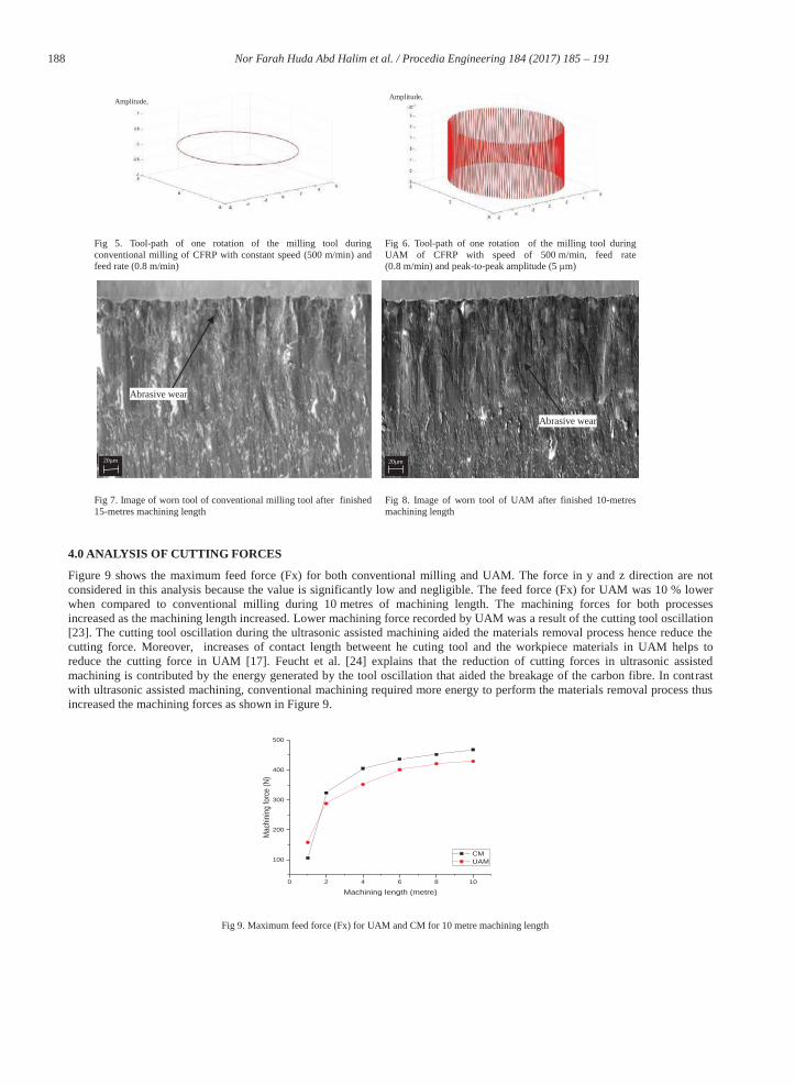
Figure 4 compares the progression of tool wear for conventional milling and ultrasonic assisted milling of CFRP. The pattern of tool wear for both processes indicates that for the first 8 m the tool wear was at a similar rate. When approaching 10 m of machining length, an average of tool wear for UAM approached the maximum wear band recommended by the industry which is 110 μm. For the conventional milling, it was possible to machine a further 5 m up to 15 m before the tool reached the maximum wear band. At 10 m machining length, the conventional milling tool exhibited just 80 μm of wear, which was 29 % less than the UAM tool. This finding is similar to Janghorbanian et al. [20] where they reported that the tool wore out faster during UAM compared to conventional milling of AISI 304. The increased tool wear in UAM can be attributed on the whole to the motion of the cutting tool due to the ultrasonic vibration. During UAM, the tool rotates, vibrates and moves at the same time which increases its contact length, hence, creating more abrasion between the tool and workpiece. The oscillation of the cutting tool in z-direction created more interaction between the tool and the workpiece thus increase the tool wear of the cutting tool. Figures 5 and 6 illustrate the tool path for conventional milling and UAM showing that the tool in UAM travelled a longer distance when compared with conventional milling under the same machining cycle. As a result, the tool for UAM worn out faster when compared with the conventional milling. In contrast with conventional milling, the tool only rotated and moved along the machine path hence reduce the contact length between the cutting tool and the workpiece material. Inspection of both tools under Scanning Electron Microscopy confirmed that the wear mechanism for both UAM and conventional milling tool were abrasive wear (Fig. 7 and 8).
0 2 4 6 8 10 12 14 16
0
20
40
60
80
100
120
Tool
Wea
r (um
)
Machining length (m)
CM UAM
Fig 4. Tool wear of UAM and CM with maximum wear limit of 110 μm recommended by industry
CFRP panel
FLIR thermal camera
CFRP strip
Dynamometer
Cutting Tool
Ultrasonic actuator
(a) (b)
188 Nor Farah Huda Abd Halim et al. / Procedia Engineering 184 ( 2017 ) 185 – 191
Fig 5. Tool-path of one rotation of the milling tool during conventional milling of CFRP with constant speed (500 m/min) and feed rate (0.8 m/min)
Fig 6. Tool-path of one rotation of the milling tool during UAM of CFRP with speed of 500 m/min, feed rate (0.8 m/min) and peak-to-peak amplitude (5 μm)
Fig 7. Image of worn tool of conventional milling tool after finished 15-metres machining length
Fig 8. Image of worn tool of UAM after finished 10-metres machining length
4.0 ANALYSIS OF CUTTING FORCES
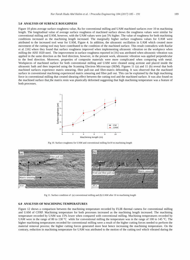
Figure 9 shows the maximum feed force (Fx) for both conventional milling and UAM. The force in y and z direction are not considered in this analysis because the value is significantly low and negligible. The feed force (Fx) for UAM was 10 % lower when compared to conventional milling during 10 metres of machining length. The machining forces for both processes increased as the machining length increased. Lower machining force recorded by UAM was a result of the cutting tool oscillation [23]. The cutting tool oscillation during the ultrasonic assisted machining aided the materials removal process hence reduce the cutting force. Moreover, increases of contact length betweent he cuting tool and the workpiece materials in UAM helps to reduce the cutting force in UAM [17]. Feucht et al. [24] explains that the reduction of cutting forces in ultrasonic assisted machining is contributed by the energy generated by the tool oscillation that aided the breakage of the carbon fibre. In contrast with ultrasonic assisted machining, conventional machining required more energy to perform the materials removal process thus increased the machining forces as shown in Figure 9.
0 2 4 6 8 10
100
200
300
400
500
CM UAM
Mac
hini
ng fo
rce
(N)
Machining length (metre)
Fig 9. Maximum feed force (Fx) for UAM and CM for 10 metre machining length
20μm 20μm
Amplitude, Amplitude,
Abrasive wear
Abrasive wear
189 Nor Farah Huda Abd Halim et al. / Procedia Engineering 184 ( 2017 ) 185 – 191
5.0 ANALYSIS OF SURFACE ROUGHNESS
Figure 10 plots average surface roughness value, Ra for conventional milling and UAM machined surfaces over 10 m machining length. The longitudinal value of average surface roughness of machined surface shows the roughness values were similar for conventional milling and UAM, however, with the UAM values were just 5% higher. The value of roughness for both machining conditions increased as the machining length increased. The marginally higher surface roughness values for UAM were attributed to the increased tool wear for UAM, Figure 4. In addition, the ultrasonic oscillation in UAM which created more movement of the cutting tool may have contributed to the condition of the machined surface. This result contradicts with Razfar et al. [16] where they found that surface roughness improved when implementing ultrasonic vibration on the workpiece when milling the AISI 1020 steel. The improvement in surface roughness reported in [16] was attributed when ultrasonic vibration was applied in the same direction as the feed direction, however, in the present work, ultrasonic vibration was applied perpendicular to the feed direction. Moreover, properties of composite materials were more complicated when comparing with metal. Workpieces of machined surface for both conventional milling and UAM were cleaned using acetone and placed inside the ultrasonic bath and then inspected using the Scanning Electron Microscopy (SEM). Figures 11 (a) and 11 (b) reveal that both machined surfaces experience matrix smearing, fibre pull-out and fibre-matrix debonding. It was observed that the machined surface in conventional machining experienced matrix smearing and fibre pull out. This can be explained by the high machining force in conventional milling that created shearing effect between the cutting tool and the machined surface. It was also found on the machined surface that the matrix resin was plastically deformed suggesting that high machining temperature was a feature of both processes.
0 2 4 6 8 10
2
3
4
5
6
7
CM UAM
Surfa
ce ro
ughn
ess
(um
)
Machining length (m)
Fig 10. Surface roughness for UAM and conventional milling for10 m machining length
Fig 11. Surface condition of (a) conventional milling and (b) UAM after 10 m machining length
6.0 ANALYSIS OF MACHINING TEMPERATURES
Figure 12 shows a comparison between the machining temperature recorded by FLIR thermal camera for conventional milling and UAM of CFRP. Machining temperature for both processes increased as the machining length increased. The machining temperature recorded by UAM was 15% lower when compared with conventional milling. Machining temperatures recorded by UAM were in the range of 80 to 130 °C while for conventional milling the temperature was in the range of 100 to 145 °C. The higher machining temperatures recorded for conventional milling were a result of the higher cutting forces needed to perform the material removal process; the higher cutting forces generated more heat hence increasing the machining temperature. On the contrary, reduction in machining temperature for UAM was attributed to the motion of the cutting tool which vibrated during the
(a) (b)
Matrix smearing
Fibre pull-out
Matrix smearingVoid and fibre pull-out

190 Nor Farah Huda Abd Halim et al. / Procedia Engineering 184 ( 2017 ) 185 – 191
machining. The vibration of the cutting tool created the air medium which aided the cooling process of the cutting tool during machining of CFRP. However, the machining temperature recorded was not the actual machining temperature while machining CFRP. The actual tool-tip temperature was not recorded in this study.
0 2 4 6 8 10
40
60
80
100
120
140
Mac
hini
ng te
mpe
ratu
re (°
C)
Machining length (m)
CM UAM
Fig 12. Maximum machining temperature recorded by FLIR thermal camera for UAM and conventional milling.
Further analysis of the machined surface was performed using Different Scanning Calorimetry (DSC) analysis to understand the effect of the machining temperature on the machined surface. In addition, machined surfaces were tested using DSC analysis. Figure 13 shows that the glass transition temperature, Tg curve for the unmachined sample was 272 °C (within the manufacturer specified range). Following machining by both methods the Tg had moved and new melting peaks were indicated at 76 °C and 65 °C, respectively, indicating that the resin has either degraded considerably as a result of experiencing high machining temperatures or further chemical species are being liberated from the sample during the machining process. This result suggests that the material properties have been changed due to the high machining temperature. The machining temperature at the workpiece/cutting tool interface could be significantly higher than the temperatures recorded using the thermal imaging hardware. As confirmation that the workpiece material experienced machining temperatures more than 150 °C a sample of unmachined CFRP was heated up to 150 °C in an oven and then tested using DSC. The result shown in Figure 14 confirmed that the CFRP did not experience any shift in glass transition temperature, or new peaks would be seen if heated up to 150 °C. Thus, the shift in glass transition temperature measured from the machined surface samples for both conventional milling and UAM, Figure 13, suggests that the actual machining temperature in both processes was higher than the temperatures recorded using thermal imaging hardware. Further investigations to determine the machining temperature and the identification of the lower temperature peaks are still ongoing.
0 50 100 150 200 250 300 350
-0.3
-0.2
-0.1
0.0
0.1
0.2
270
71.3
333
68.5
Hea
t Flo
w (
Wg^
-1)
Temperature (°C)
Unmachined
UAM
CM
0 50 100 150 200 250 300 350-0.6
-0.4
-0.2
0.0
27
0
Hea
t Flo
w (
Wg^
-1)
Temperature (°C)
Fig 13. Machined surface analysis using Different Scanning Calorimetry (DSC) with a heating rate of 10 °C/min showing that the glass transition temperature, Tg of the resin shifted from 272 °C to 76 °C and 65 °C for both UAM and conventional milling at 10 m machining length, respectively.
Fig 14. Analysis of CFRP that has been heated up to 150 °C with a heating rate of 10 °C/min from 25 to 290 °C

191 Nor Farah Huda Abd Halim et al. / Procedia Engineering 184 ( 2017 ) 185 – 191
CONCLUSIONS
Based on the observation and analysis of ultrasonic assisted milling and conventional milling of CFRP with constant speed (500 m/min), feed (800 mm/min) and radial depth of cut (2 mm), the following conclusions are drawn: a) Experimental results indicate that the tool wore out faster during UAM when compared with conventional milling. The effect
of ultrasonic vibration on the cutting tool generated more friction between the tool and surface hence wore out the tool faster. Abrasive wear was a feature of both tools.
b) In term of cutting forces, the maximum cutting forces recorded in UAM were lower (10 %) when compared to conventional milling. Tool vibration aided the material removal process in UAM.
c) However, the average surface roughness, Ra for UAM was higher between 5 to 25 % compares with conventional milling. Worse surface quality in UAM was attributed to the motion of the tool which was perpendicular to the machining direction generating a rougher machined surface.
d) DSC analysis of machined surfaces revealed a shift in the glass transition temperature from 272°C to ~70°C for both CM and UAM indicating that the resin had degraded considerably as a result of experiencing high machining temperatures. Further investigations to determine the machining temperature required to result in this shift are still ongoing.
ACKNOWLEDGMENTS
The research presented within this paper was supported by Innovate UK through the WMG Centre High-Value Manufacturing (HVM) in collaboration with BAE Systems, who provided CFRP panels and PCD tool. The authors would also like to thank the Government of Malaysia and International Islamic University Malaysia for providing funding for Nor Farah Huda and Mr. Darren Grant (WMG, University of Warwick) for his assistance during machining. REFERENCES [1] J. Y. Sheikh-Ahmad, Machining of polymer composites: Springer, 2009. [2] H. Hocheng, H. Y. Puw, and Y. Huang, "Preliminary study on milling of unidirectional carbon fibre-reinforced plastics," Composites Manufacturing,
Vol. 4, pp. 103-108, 1993. [3] H. Hocheng and H. Puw, "On drilling characteristics of fiber-reinforced thermoset and thermoplastics," International Journal of Machine Tools and
Manufacture, Vol. 32, pp. 583-592, 1992. [4] A. I. Azmi, R. J. T. Lin, and D. Bhattacharyya, "Machinability study of glass fibre-reinforced polymer composites during end milling," The
International Journal of Advanced Manufacturing Technology, Vol. 64, pp. 247-261, 2013. [5] M. H. El-Hofy, S. L. Soo, D. K. Aspinwall, W. M. Sim, D. Pearson, and P. Harden, "Factors Affecting Workpiece Surface Integrity in Slotting of
CFRP," Procedia Engineering, Vol. 19, pp. 94-99, 2011. [6] J. P. Davim, P. Reis, and C. C. António, "A study on milling of glass fiber reinforced plastics manufactured by hand-lay up using statistical analysis
(ANOVA)," Composite Structures, Vol. 64, pp. 493-500, 2004. [7] J. P. Davim and P. Reis, "Damage and dimensional precision on milling carbon fiber-reinforced plastics using design experiments," Journal of
Materials Processing Technology, Vol. 160, pp. 160-167, 2005. [8] M. Haddad, R. Zitoune, H. Bougherara, F. Eyma, and B. Castanié, "Study of trimming damages of CFRP structures in function of the machining
processes and their impact on the mechanical behavior," Composites Part B: Engineering, Vol. 57, pp. 136-143, 2014. [9] M. Ucar and Y. Wang, "End-milling machinability of a carbon fiber reinforced laminated composite," Journal of advanced materials, Vol. 37, pp. 46-
52, 2005. [10] D. Kalla, J. Sheikh-Ahmad, and J. Twomey, "Prediction of cutting forces in helical end milling fiber reinforced polymers," International Journal of
Machine Tools and Manufacture, Vol. 50, pp. 882-891, 2010. [11] A. I. Azmi, "Machinability study of fibre-reinforced polymer matrix composites," ResearchSpace@ Auckland, 2012. [12] M. K. Nor Khairusshima, C. H. Che Hassan, A. G. Jaharah, A. K. M. Amin, and A. N. Md Idriss, "Effect of chilled air on tool wear and workpiece
quality during milling of carbon fibre-reinforced plastic," Wear, Vol. 302, pp. 1113-1123, 2013. [13] T. Yashiro, T. Ogawa, and H. Sasahara, "Temperature measurement of cutting tool and machined surface layer in milling of CFRP," International
Journal of Machine Tools and Manufacture, Vol. 70, pp. 63-69, 2013. [14] M. Ramulu, "Machining and surface integrity of fibre-reinforced plastic composites," Sadhana, Vol. 22, pp. 449-472, 1997. [15] W. Hintze, D. Hartmann, and C. Schütte, "Occurrence and propagation of delamination during the machining of carbon fibre reinforced plastics
(CFRPs) – An experimental study," Composites Science and Technology, Vol. 71, pp. 1719-1726, 2011. [16] M. Razfar, P. Sarvi, and M. A. Zarchi, "Experimental investigation of the surface roughness in ultrasonic-assisted milling," Proceedings of the
Institution of Mechanical Engineers, Part B: Journal of Engineering Manufacture, Vol. 225, pp. 1615-1620, 2011. [17] M. M. Abootorabi Zarchi, M. R. Razfar, and A. Abdullah, "Influence of ultrasonic vibrations on side milling of AISI 420 stainless steel," The
International Journal of Advanced Manufacturing Technology, Vol. 66, pp. 83-89, 2013. [18] H. Takeyama and N. Iijima, "Machinability of Glassfiber Reinforced Plastics and Application of Ultrasonic Machining," CIRP Annals -
Manufacturing Technology, Vol. 37, pp. 93-96, 1988. [19] M. M. A. Zarchi, M. R. Razfar, and A. Abdullah, "Investigation of the effect of cutting speed and vibration amplitude on cutting forces in ultrasonic-
assisted milling," Proceedings of the Institution of Mechanical Engineers, Part B: Journal of Engineering Manufacture, Vol. 226, pp. 1185-1191, 2012.
[20] J. Janghorbanian, M. R. Razfar, and M. M. A. Zarchi, "Effect of cutting speed on tool life in ultrasonic-assisted milling process," Proceedings of the Institution of Mechanical Engineers, Part B: Journal of Engineering Manufacture, Vol. 227, pp. 1157-1164, 2013.
[21] V. A. Phadnis, A. Roy, and V. V. Silberschmidt, "A Finite Element Model of Ultrasonically Assisted Drilling in Carbon/Epoxy Composites," Procedia CIRP, Vol. 8, pp. 141-146, 2013.
[22] X.-H. Shen, J.-H. Zhang, H. Li, J.-J. Wang, and X.-C. Wang, "Ultrasonic vibration-assisted milling of aluminum alloy," The International Journal of Advanced Manufacturing Technology, Vol. 63, pp. 41-49, 2012.
[23] A. H. N. F. Huda, H. Ascroft, and S. Barnes, "Machinability Study of Ultrasonic Assisted Machining (UAM) of Carbon Fibre Reinforced Plastic (CFRP) with Multifaceted Tool," Procedia CIRP, Vol. 46, pp. 488-491, 2016.
[24] Feucht, F., Ketelaer, J., Wolff, A., Mori, M., & Fujishima, M. "Latest machining Technologies of hard-to-cut materials by ultrasonic Machine Tool". Procedia CIRP, 14, 148-152 (2014).