Analysis of the internal heat losses in a thermoelectric generator · Analysis of the internal heat...
12
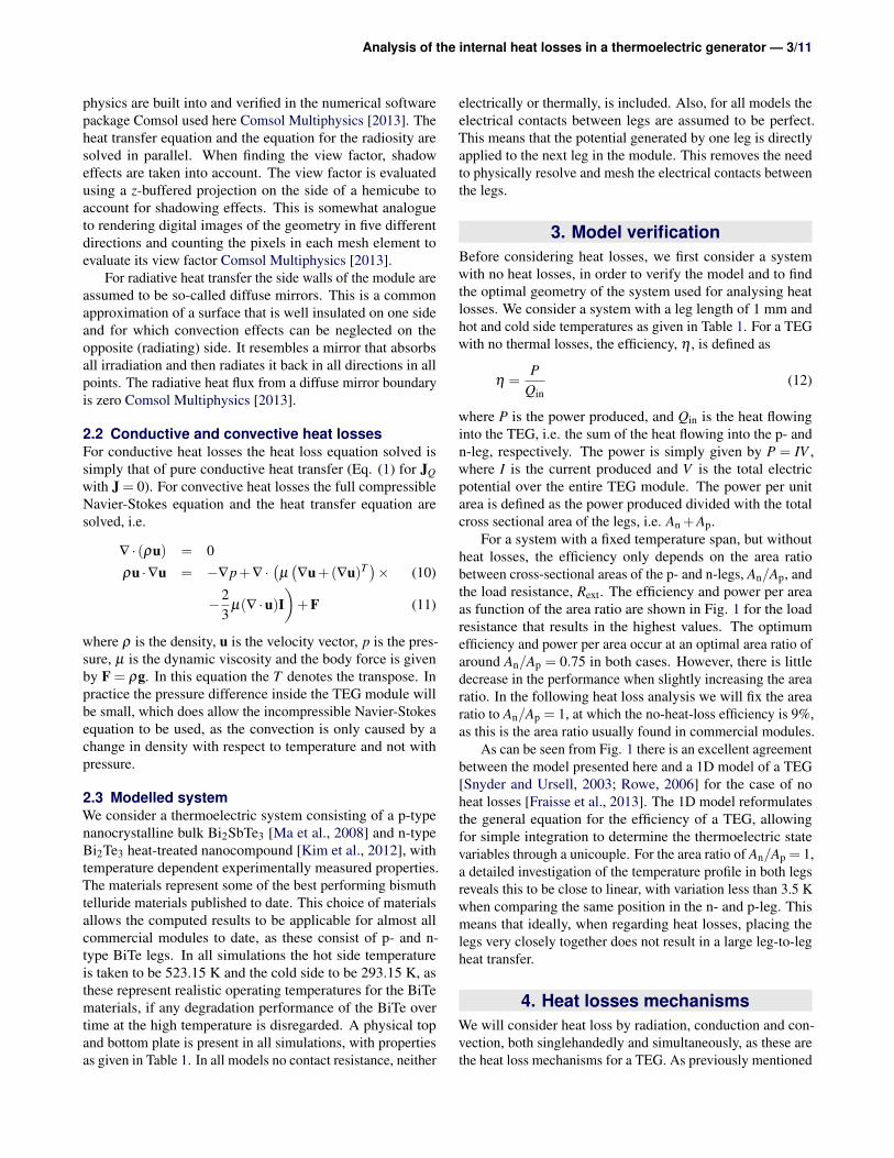
General rights Copyright and moral rights for the publications made accessible in the public portal are retained by the authors and/or other copyright owners and it is a condition of accessing publications that users recognise and abide by the legal requirements associated with these rights. Users may download and print one copy of any publication from the public portal for the purpose of private study or research. You may not further distribute the material or use it for any profit-making activity or commercial gain You may freely distribute the URL identifying the publication in the public portal If you believe that this document breaches copyright please contact us providing details, and we will remove access to the work immediately and investigate your claim. Downloaded from orbit.dtu.dk on: Apr 07, 2020 Analysis of the internal heat losses in a thermoelectric generator Bjørk, Rasmus; Christensen, Dennis Valbjørn; Eriksen, Dan; Pryds, Nini Published in: International Journal of Thermal Sciences Link to article, DOI: 10.1016/j.ijthermalsci.2014.06.003 Publication date: 2014 Link back to DTU Orbit Citation (APA): Bjørk, R., Christensen, D. V., Eriksen, D., & Pryds, N. (2014). Analysis of the internal heat losses in a thermoelectric generator. International Journal of Thermal Sciences, 85, 12-20. https://doi.org/10.1016/j.ijthermalsci.2014.06.003
Transcript of Analysis of the internal heat losses in a thermoelectric generator · Analysis of the internal heat...
General rights Copyright and moral rights for the publications made accessible in the public portal are retained by the authors and/or other copyright owners and it is a condition of accessing publications that users recognise and abide by the legal requirements associated with these rights.
Users may download and print one copy of any publication from the public portal for the purpose of private study or research.
You may not further distribute the material or use it for any profit-making activity or commercial gain
You may freely distribute the URL identifying the publication in the public portal If you believe that this document breaches copyright please contact us providing details, and we will remove access to the work immediately and investigate your claim.
Downloaded from orbit.dtu.dk on: Apr 07, 2020
Analysis of the internal heat losses in a thermoelectric generator
Bjørk, Rasmus; Christensen, Dennis Valbjørn; Eriksen, Dan; Pryds, Nini
Published in:International Journal of Thermal Sciences
Link to article, DOI:10.1016/j.ijthermalsci.2014.06.003
Publication date:2014
Link back to DTU Orbit
Citation (APA):Bjørk, R., Christensen, D. V., Eriksen, D., & Pryds, N. (2014). Analysis of the internal heat losses in athermoelectric generator. International Journal of Thermal Sciences, 85, 12-20.https://doi.org/10.1016/j.ijthermalsci.2014.06.003

Published in International Journal of Thermal Sciences, Vol. 85, 12–20, 2014DOI: 10.1016/j.ijthermalsci.2014.06.003
Analysis of the internal heat losses in athermoelectric generatorR. Bjørk, D. V. Christensen, D. Eriksen and N. Pryds
AbstractA 3D thermoelectric numerical model is used to investigate different internal heat loss mechanisms for athermoelectric generator with bismuth telluride p- and n-legs. The model considers all thermoelectric effects,temperature dependent material parameters and simultaneous convective, conductive and radiative heat losses,including surface to surface radiation. For radiative heat losses it is shown that for the temperatures consideredhere, surface to ambient radiation is a good approximation of the heat loss. For conductive heat transfer themodule efficiency is shown to be comparable to the case of radiative losses. Finally, heat losses due to internalnatural convection in the module is shown to be negligible for the millimetre sized modules considered here. Thecombined case of radiative and conductive heat transfer resulted in the lowest efficiency. The optimized loadresistance is found to decrease for increased heat loss. The leg dimensions are varied for all heat losses casesand it is shown that the ideal way to construct a TEG module with minimal heat losses and maximum efficiencyis to either use a good insulating material between the legs or evacuate the module completely, and use smalland wide legs closely spaced.
Department of Energy Conversion and Storage, Technical University of Denmark - DTU, Frederiksborgvej 399, DK-4000 Roskilde, Denmark*Corresponding author: [email protected]
1. IntroductionPower generation through the thermoelectric effect is a subjectof increasing interest both scientifically and commercially.The performance of a thermoelectric generator (TEG) is oftenestimated using numerical modelling before actual physicalmodules are constructed. This allows for the development ofnew and better thermoelectric generators in a cost effectivemanner, as well as for designing and optimizing modules toachieve as high an efficiency as possible. To accurately designthe most efficient module possible, a large number of factorsmust be taken into account including geometric parameters,temperature dependence of the material properties, heat lossesand thermal and electrical contact resistances.
A substantial number of numerical models of thermoelec-tric generators, both of unicouples and modules, have beenpublished, but most of these only consider the ideal case withno heat losses and contact resistances. While the latter effectpresents some challenges to determine experimentally, it caneasily be included in a numerical model, if the contact resis-tance is known from experimental measurements. Includingheat losses in a numerical model is more troublesome, but isnever the less important as heat losses can significantly de-grade the performance of a TEG. Experimental thermoelectricgenerator output is known to deviate from a TEG model withno heat losses; for example have heat losses determined ex-perimentally previously been reported to reduce the efficiencyby about 40-50% [El-Genk et al., 2006; Hung et al., 2014].
Heat losses have been considered in numerical models ofTEGs in both one, two and three dimensional models. Muto
et al. [2009] considered a 1D TEG model where the radiativeheat loss is given by Stefan-Boltzmann law for a specifiedperimeter length, whereas Meng et al. [2011] consider a 1Dmodel including all heat losses (radiative, conductive and con-vective) by assuming the temperature in the air gap betweenthe TEG legs to be equal to that in the legs themselves. Forthree dimensions a substantial number of publications existswhere a TEG is modelled, however without heat losses, usinga finite element model (FEM) [Kim et al., 2009; Ebling et al.,2010; Jang et al., 2011; Seetawan et al., 2012; Wang et al.,2013; Huang et al., 2013; Wang et al., 2014]. When heatlosses are considered, most frequently the models reportedin literature only consider a single heat loss mechanism andtypically the heat loss mechanisms are simplified substantially.For general heat loss and for fluid flow problems often onlyheat loss through a simple heat transfer coefficient has beenconsidered [Harris et al., 2006; Chen et al., 2011; Reddy et al.,2013; Bauknecht et al., 2012; Yang et al., 2011; Wang et al.,2012]. For heat loss through radiation, only surface to ambientradiation and not surface to surface radiation has been consid-ered [Saber and El-Genk, 2002; Ziolkowski et al., 2010; Yanget al., 2011; Reddy et al., 2013]. Using the simplified physicalassumptions presented above, different heat loss mechanismshave been compared, where it was found that the convectionallosses are greatest followed by radiation and thermal conduc-tion of a solid filling material within the voids of the module[Ziolkowski et al., 2010].
Here we consider the performance of a TEG, accountingfor heat losses in full detail numerically by modelling surface

Analysis of the internal heat losses in a thermoelectric generator — 2/11
to surface radiation as well as conductive and convective heatlosses, where the flow field is completely modelled for thelatter. For each heat loss mechanism the influence of bothgeometrical factors and physical parameters are investigated,with the aim of determining the influence of the various heatloss mechanisms on the performance of a TEG. This knowl-edge will allow for the optimal TEG with regards to cost andefficiency to be designed.
2. Three dimensional TEG modelA 3D thermoelectric model of a module with p- and n-typelegs, electrodes and substrates has been set up and imple-mented in the commercial finite element software ComsolMultiphysics [Comsol Multiphysics, 2013]. The coupled dif-ferential equations describe the electrical current density, J,and the heat flux, JQ, as [Yang et al., 2012]
−J = σ∇V +σα∇T
JQ = −κ∇T +T αJ (1)
Here σ is the electrical conductivity, V is the electrical poten-tial, α is the Seebeck coefficient, T is the temperature, and κ
is the thermal conductivity. In the equation for J, the first termis Ohm’s law, while the second describes the Seebeck effect.In the equation for JQ the first term describes Fourier heatconduction, while the latter describes the Peltier effect. Nu-merically, the latter term in the equation for J is implementedas an “External Current Density” in Comsol, while the expres-sion for JQ is modified through a “Weak Expression”1.
In steady state operation the current density is divergence-free
∇ ·J = 0 , (2)
whereas the heat flux is given by
∇ ·JQ = −∇ · (V J) . (3)
For the case of steady state operation, the energy accumu-lation, e, must be zero, i.e.
e = ∇ · (κ∇T )−∇ · ((V +T α)J) = 0. (4)
Remembering that the current is divergence-free the energyaccumulation becomes
e = ∇ · (κ∇T )−J · (σ−1J)−T ∇α ·J. (5)
where the middle term is the Joule heating and the latterterm is the Thomson effect, both of which are present in thesimulations.
These equations are solved on a finite element mesh forthe desired geometry and thermal and electrical boundaryconditions. The geometry considered here is that of severalunicouples connected electrically in serial and thermally in
1The latest version of Comsol, 4.4, has built-in support of thermoelectricmaterials. The implementation discussed here is equivalent to this implemen-tation.
parallel into a module. Either the material properties of theelectrodes must be specified or an infinitely good electricalcontact can be assumed. An external electrical load resistance,Rext, is applied to the TEG. This is modelled as a boundarycondition, described as a thin sheet of resistive material, withconductivity σs and thickness ds, connected to a referencepotential Vref = 0 in one end of the module. The equation forthis boundary condition is
n · (J1 −J2) =σs
ds(V −Vref) , (6)
where n is the normal vector to the surface. The other endof the module is assumed connected to ground, V = 0. Allsurfaces of the TE legs not exposed to the electrodes areassumed to be electrically insulating, i.e. J · n = 0, whilethe current is conserved over all internal boundaries. Finally,a contact resistance can be specified on all boundaries, inorder to model an imperfect joining between the legs and theelectrodes. However, here we assume the joining to be perfectin all cases.
Thermally, any two parameters out of the hot side tem-perature, cold side temperature, hot side heat flux and coldside heat flux must be specified as input parameters to themodel. The thermal boundary conditions depend on the heatlosses modelled, e.g. whether an infinite module or a moduleof finite size, with heat loss through the sides of the module,is considered. Here, we consider modules where no heat islost through the sides of the module, but only lost internallyin the module.
2.1 Radiative heat lossesIf radiative heat losses are considered, for a surface radiatingthrough a transparent medium, the radiative heat flux is givenby the difference between the incoming radiation and theradiation leaving the surface, i.e.
Q = ε(G−σSBT 4) (7)
where ε is the emissivity, G is the incoming radiative heat flux,or irradiation, and σSB = 5.67 ∗ 10−8 Wm−2K−4 is Stefan-Boltzmanns constant. The irradiation can in general be writtenas
G = Gm +FambσSBT 4amb (8)
where Gm is the mutual irradiation from other surfaces, Fambis the ambient view factor, i.e. the fraction of the field of viewthat is not covered by other surfaces, and Tamb is the ambienttemperature. The mutual irradiation will depend on the totaloutgoing radiative flux, or radiosity, J, at every other point inview. This results in an implicit equation for the radiosity as
J = (1− ε)(Gm(J)+FambσSBT 4amb)+ εσSBT 4 (9)
where Gm(J) is the mutual irradiation from other surfaces,which depends on J. For the case of blackbody radiation, theradiosity only depends on the temperature of the surface, as allincoming radiation is absorbed and converted to heat. These
Analysis of the internal heat losses in a thermoelectric generator — 3/11
physics are built into and verified in the numerical softwarepackage Comsol used here Comsol Multiphysics [2013]. Theheat transfer equation and the equation for the radiosity aresolved in parallel. When finding the view factor, shadoweffects are taken into account. The view factor is evaluatedusing a z-buffered projection on the side of a hemicube toaccount for shadowing effects. This is somewhat analogueto rendering digital images of the geometry in five differentdirections and counting the pixels in each mesh element toevaluate its view factor Comsol Multiphysics [2013].
For radiative heat transfer the side walls of the module areassumed to be so-called diffuse mirrors. This is a commonapproximation of a surface that is well insulated on one sideand for which convection effects can be neglected on theopposite (radiating) side. It resembles a mirror that absorbsall irradiation and then radiates it back in all directions in allpoints. The radiative heat flux from a diffuse mirror boundaryis zero Comsol Multiphysics [2013].
2.2 Conductive and convective heat lossesFor conductive heat losses the heat loss equation solved issimply that of pure conductive heat transfer (Eq. (1) for JQwith J = 0). For convective heat losses the full compressibleNavier-Stokes equation and the heat transfer equation aresolved, i.e.
∇ · (ρu) = 0ρu ·∇u = −∇p+∇ ·
(µ(∇u+(∇u)T )× (10)
−23
µ(∇ ·u)I)+F (11)
where ρ is the density, u is the velocity vector, p is the pres-sure, µ is the dynamic viscosity and the body force is givenby F = ρg. In this equation the T denotes the transpose. Inpractice the pressure difference inside the TEG module willbe small, which does allow the incompressible Navier-Stokesequation to be used, as the convection is only caused by achange in density with respect to temperature and not withpressure.
2.3 Modelled systemWe consider a thermoelectric system consisting of a p-typenanocrystalline bulk Bi2SbTe3 [Ma et al., 2008] and n-typeBi2Te3 heat-treated nanocompound [Kim et al., 2012], withtemperature dependent experimentally measured properties.The materials represent some of the best performing bismuthtelluride materials published to date. This choice of materialsallows the computed results to be applicable for almost allcommercial modules to date, as these consist of p- and n-type BiTe legs. In all simulations the hot side temperatureis taken to be 523.15 K and the cold side to be 293.15 K, asthese represent realistic operating temperatures for the BiTematerials, if any degradation performance of the BiTe overtime at the high temperature is disregarded. A physical topand bottom plate is present in all simulations, with propertiesas given in Table 1. In all models no contact resistance, neither
electrically or thermally, is included. Also, for all models theelectrical contacts between legs are assumed to be perfect.This means that the potential generated by one leg is directlyapplied to the next leg in the module. This removes the needto physically resolve and mesh the electrical contacts betweenthe legs.
3. Model verificationBefore considering heat losses, we first consider a systemwith no heat losses, in order to verify the model and to findthe optimal geometry of the system used for analysing heatlosses. We consider a system with a leg length of 1 mm andhot and cold side temperatures as given in Table 1. For a TEGwith no thermal losses, the efficiency, η , is defined as
η =P
Qin(12)
where P is the power produced, and Qin is the heat flowinginto the TEG, i.e. the sum of the heat flowing into the p- andn-leg, respectively. The power is simply given by P = IV ,where I is the current produced and V is the total electricpotential over the entire TEG module. The power per unitarea is defined as the power produced divided with the totalcross sectional area of the legs, i.e. An +Ap.
For a system with a fixed temperature span, but withoutheat losses, the efficiency only depends on the area ratiobetween cross-sectional areas of the p- and n-legs, An/Ap, andthe load resistance, Rext. The efficiency and power per areaas function of the area ratio are shown in Fig. 1 for the loadresistance that results in the highest values. The optimumefficiency and power per area occur at an optimal area ratio ofaround An/Ap = 0.75 in both cases. However, there is littledecrease in the performance when slightly increasing the arearatio. In the following heat loss analysis we will fix the arearatio to An/Ap = 1, at which the no-heat-loss efficiency is 9%,as this is the area ratio usually found in commercial modules.
As can be seen from Fig. 1 there is an excellent agreementbetween the model presented here and a 1D model of a TEG[Snyder and Ursell, 2003; Rowe, 2006] for the case of noheat losses [Fraisse et al., 2013]. The 1D model reformulatesthe general equation for the efficiency of a TEG, allowingfor simple integration to determine the thermoelectric statevariables through a unicouple. For the area ratio of An/Ap = 1,a detailed investigation of the temperature profile in both legsreveals this to be close to linear, with variation less than 3.5 Kwhen comparing the same position in the n- and p-leg. Thismeans that ideally, when regarding heat losses, placing thelegs very closely together does not result in a large leg-to-legheat transfer.
4. Heat losses mechanismsWe will consider heat loss by radiation, conduction and con-vection, both singlehandedly and simultaneously, as these arethe heat loss mechanisms for a TEG. As previously mentioned

Analysis of the internal heat losses in a thermoelectric generator — 4/11
Area ratio, An/A
p
η [%
]
0 0.5 1 1.5 24
6
8
10
12Opt. for efficiencyOpt. for power/area1D model results
20
40
60
80
100
120
140
160
Opt
imiz
ed R
load
[mΩ
]
10
20
30
40
50
60
70P
ower
/are
a [m
W m
m−
2 ]
0 0.5 1 1.5 24
6
8
10
12
Figure 1. The optimized efficiency, η , and power per unitarea and corresponding load resistances as function of arearatio. Also shown are results calculated using a 1D numericalmodel [Snyder and Ursell, 2003; Rowe, 2006].
we consider legs with dimensions of 1×1×1 mm3, which isclose to the optimal area ratio and to the dimensions usedin commercial TEG modules [Marlow Industries, Inc, 2013].We have not optimized the cross-sectional area ratio betweenn- and p-legs for the different heat loss cases, as we wish tocompare the magnitude of the different heat loss mechanismsfor identical TEGs. For all modelled systems the external loadresistance that optimizes the efficiency for the given system isfound.
We consider whole modules, consisting of n × n-legs,equidistantly spaced and topped with a hot plate and witha cold bottom plate. In some cases the efficiency is the sameregardless of the value of n, but if this is not the case weconsider modules with 2×2 or 4×4 legs. Such a case couldbe surface to surface radiation, where the number of visiblelegs changes depending on the total number of legs. The legsare separated by a distance, termed the leg separation distance,and the top and bottom plates extend half of this distance outfrom the legs, as also shown in Fig. 2. In this way the areaof the legs compared to the area of the plates does not varybased on the number of legs in the module.
The module has adiabatic side walls. Thus there is noexternal heat loss from the module, but only internal losses,e.g. heat passing directly from the hot plate to the cold plate,bypassing the legs. Modelling heat loss through the side wallswould require knowing the conditions outside of the TEG, i.e.simulating the precise environment that the TEG is placed in,which would mean that the heat losses could not be generallycalculated. An illustration of a slice through the 3D systemmodelled is shown in Fig. 2, as well as some illustrations ofthe different heat transfer mechanisms considered.
For a module with heat losses, we will consider the systemefficiency in the same way as for the no heat loss case, i.e.using Eq. (12), but where Qin is taken as the total heat that is
# of mesh elements
Nor
mal
ized
η
104
105
106
0.96
0.97
0.98
0.99
1
2x2, Vacuum: Rad.4x4, Vacuum: Rad.2x2, Air: Conv. + Cond. + Rad.2x2, Air: Cond. + Rad.
Figure 3. The normalized efficiency as function of thenumber of mesh elements of the finite element mesh for someof the different heat loss mechanisms and different number oflegs considered. The chosen mesh resolutions have beenindicated for the different cases with a circle.
flowing from the hot side. This means that for e.g. a system inwhich the legs are embedded in a thermal insulator, the heatflowing directly from the hot side to the cold side through thethermal insulator, bypassing the legs completely, is includedin the efficiency. Thus the efficiency measures the fractionof heat deducted from the hot side that is transformed intoelectricity by the TEG.
For each model containing different heat loss mechanismsa mesh size analysis was conducted to ensure that the resultswere not a function of mesh size. The normalized efficiencyas function of mesh size is shown in Fig. 3, where the meshused for the subsequent calculations have also been indicated.
5. Heat losses by conduction
We first consider the isolated case of heat losses only occur-ring by conduction. This corresponds to the situation wherethe legs in a TEG are surrounded by a thermally insulatingmaterial with a given thermal conductivity, κ , and an infiniteelectrical resistivity. We assume that no heat is lost throughthe outer sides of the module. As the temperature profiles inthe n- and p-legs are almost identical in the no heat loss case,and as the legs have the same size, the efficiency is the sameregardless of both the number of legs and the absolute size ofthe module.
The parameters varied for this system were leg separa-tion values of 0.25-4 mm in steps of 0.25 mm and κ = 10x
Wm−1K−1 from x = −3 to 0 in steps of 0.5. Shown in Fig. 4is a surface plot of the efficiency as function of the leg sepa-ration distance and the thermal conductivity of the insulatormaterial. The efficiency decreases for both increasing thermalconductivity and leg separation. This is expected as higherthermal conductivities and leg separations reduce the thermal

Analysis of the internal heat losses in a thermoelectric generator — 5/11
Thot
Tcold = TambLeg separation½ Leg separation
Radiation
n-leg
Top plate
Bottom plate
Di"
use
mirro
r, Q =
0
Convection
Conduction
x
yz
Streamlines
Direction
of gravity
Hot top plate
0.40.81.6 1.2 0
Radiative heat #ux [W/m2]
Radiation Conduction
2428 26 0.9 0.8 0.7
.
...
Temperature gradient [K/m]
Convective speed [mm/s]
p-leg
Di"
use
mirro
r, Q =
0
Legs
3.02.01.00-1x10³
2.02.22.6 2.4
1
Conductive heat #ux [W/m2]x104
...
Convectionx105
Figure 2. An illustration of a slice of the thermoelectric system modelled for the different heat loss mechanisms considered. Aspreviously mentioned the electrical connection between the legs is assumed to be perfect, removing the need to resolve theelectrical contacts. The full 3D system is modelled. The distance between the legs is the same in the x and y directions. Thedifferent heat loss mechanisms modelled are also illustrated in the figure. The radiative heat flux for a 4x4 module includingsurface to surface radiation is shown for a leg separation distance of 1 mm, with the TEG viewed from the bottom. For the caseof convection the flow field is shown for a 3 mm leg separation 2x2 module filled with air and including surface to surfaceradiation, conduction and convection. Finally the conductive heat flux and the temperature gradient is shown for the case of a 2mm leg separation 2x2 module with a solid thermal insulator placed between the legs.
Module Thot = 523.15 K Tcold = 293.15 K ε = 1Legs and plates xlegs = ylegs = zlegs = 1 mm zplates = 0.1 mm κplates = 429 Wm−1K−1
Table 1. The general module parameters. The thermal conductivity of the plates is identical to Ag at room temperature.

Analysis of the internal heat losses in a thermoelectric generator — 6/11
3
4
1
5
2
67
3
2
4
5
6
8
7
34
567
8
κ, Thermal conductivity [W m−1 K−1]
8
9
Leg
sepa
ratio
n [m
m]
10−3
10−2
10−1
100
0.5
1
1.5
2
2.5
3
3.5
4
η [%
]
2
3
4
5
6
7
8
9
Figure 4. A surface plot of the efficiency, η , as function ofthe leg separation distance and the thermal conductivity ofthe insulator material. The efficiency is independent of thenumber of legs in the module.
resistance of the insulator material and thus increases the heatflux that bypasses the legs. Note that the thermal conductiv-ity of the p- and n-leg materials is around 1 Wm−1K−1 forthe materials considered here. For the thermal conductivityof still air, κ ≈ 0.02−0.04 W m−1 K−1 for the temperaturerange considered here [Lemmon et al., 2000], the efficiency is8−9% for small leg separations. Fig. 4 can be used to deter-mine the optimal insulator material if e.g. there is a significantprice difference between two insulator material, and the costper efficiency loss ratio is known.
6. Heat losses by radiation
We next consider the case of heat loss by radiation only. In thisconfiguration the sides of the module are modelled as diffusemirrors, and the module is assumed completely evacuated.We consider modules of sizes 2x2 and 4x4, to evaluate theinfluence of increasing leg number. Also, in order to comparethe importance of including surface to surface radiation, theefficiency of the 2x2 and 4x4 modules are compared to that ofa 2x2 module, where all surfaces are assumed to radiate onlyto the ambient. The efficiency as function of leg separationdistance is shown in Fig. 5. As can be seen from the figure,the efficiency of the 2x2 and 4x4 modules are comparable,with the largest difference being less than 0.2% efficiency.This means that the heat loss computed for the 2x2 modelcan be considered a good approximation of an n×n system.The difference between including surface to surface and onlysurface to ambient radiation is also seen to be small, on theorder of 0.35% efficiency. This means that the computation-ally much faster surface to ambient method can be used toestimate the radiative heat loss, at least for the temperaturesconsidered here.
Leg separation [mm]
η [%
]
1 2 3 4 5
7
7.5
8
8.5
9
No heat loss2x2, Vacuum: Rad.4x4, Vacuum: Rad.2x2, Vacuum: Amb. Rad.
Figure 5. The efficiency, η , a function of the leg separationdistance for a 2x2 and 4x4 module including surface tosurface radiation and for a 2x2 module including only surfaceto ambient radiation. Due to computational resources, onlyleg separations up to 3.5 mm are considered for the 4x4module.
7. Heat losses by convectionHeat loss by convection have been considered previously inthe literature for a TEG, by specifying a heat transfer coeffi-cient and not by modelling the actual fluid flow [Chen et al.,2011; Ziolkowski et al., 2010; Reddy et al., 2013; Bauknechtet al., 2012; Yang et al., 2011; Saber and El-Genk, 2002]. Thisapproach is a simplification of the true physical problem, inwhich the heat transfer coefficient must depend on the positionon the surface of the leg(s). Here we consider the losses dueto natural convection inside a closed and sealed module, filledwith air. The module is assumed filled with atmospheric air atatmospheric pressure, with temperature dependent properties,thus the flow is assumed to be compressible. The air is consid-ered transparent to radiation. Transport of heat can thus occurboth by radiation between surfaces (of different temperature),conduction through the air and convection. The flow of air isassumed to be laminar.
The hot and cold surfaces of the TEG will establish agradient in density, which can lead to convective cells. Thebalance of forces is between the gravitational force on thegradient in density as opposed to the viscous damping forcein the fluid. This balance is expressed by the non-dimensionalRayleigh number, RaL, defined as
RaL =gβ
να(Tb −Tt)L3 (13)
where g is the acceleration due to gravity, ν is the kinematicviscosity, α is the thermal diffusivity, β is the thermal expan-sion coefficient, Tb and Tt is the temperature of the bottom andtop plates, respectively, and L is the height of the container.
The critical Rayleigh number depends on the boundaryconditions of the system. For the rigid-rigid boundary system
Analysis of the internal heat losses in a thermoelectric generator — 7/11
of the TEG module, the critical Rayleigh number depends onwhether there is vertical velocity symmetry with respect tothe mid plane or vertical velocity antisymmetry. The formermode has one row of cells along the vertical while the latterhas two row of cells. The critical Rayleigh numbers are 1707and 17610 for the two cases, respectively.
For the TEG module, placed with the cold side on top andthe hot side on the bottom, the Rayleigh number is on theorder of 10-30 for the temperature range and size of moduleconsidered here. This means that no convection cells willdevelop inside the TEG. However, a convective flow can beestablished inside the TEG if the TEG is placed such that thehot and cold sides are vertical. In this configuration the airwill be heated as it raises along the hot vertical surface andcooled as is falls along the cold vertical surface, allowing aconvective flow to be established. This configuration meansthat the individual air currents are in maximal contact withthe heating and cooling surfaces, resulting in the largest con-vection possible. The efficiency of this configuration will beexamined below.
8. Comparing the heat loss mechanisms
We now turn to studying the efficiency as function of leg sepa-ration for a combination of the different heat loss mechanismsdescribed above. We consider the efficiency as function of theleg separation for the following cases
• Radiation losses for evacuated module.
• Conduction losses for a module filled with opaque stillair (κ = 0.035 Wm−1K−1) or still argon (κ = 0.016Wm−1K−1).
• Conduction and radiative losses for a module filledwith still transparent air.
• Convection, conductive and radiative losses for avertical module filled with transparent air.
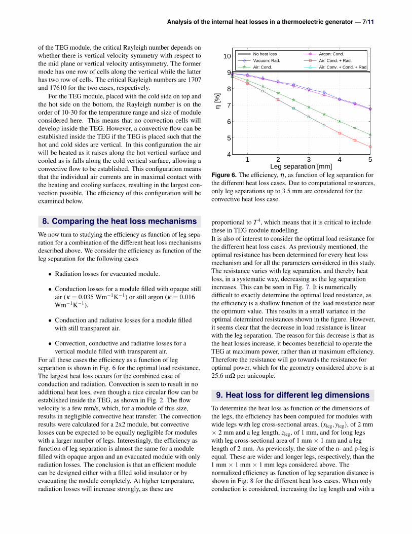
For all these cases the efficiency as a function of legseparation is shown in Fig. 6 for the optimal load resistance.The largest heat loss occurs for the combined case ofconduction and radiation. Convection is seen to result in noadditional heat loss, even though a nice circular flow can beestablished inside the TEG, as shown in Fig. 2. The flowvelocity is a few mm/s, which, for a module of this size,results in negligible convective heat transfer. The convectionresults were calculated for a 2x2 module, but convectivelosses can be expected to be equally negligible for moduleswith a larger number of legs. Interestingly, the efficiency asfunction of leg separation is almost the same for a modulefilled with opaque argon and an evacuated module with onlyradiation losses. The conclusion is that an efficient modulecan be designed either with a filled solid insulator or byevacuating the module completely. At higher temperature,radiation losses will increase strongly, as these are
Leg separation [mm]
η [%
]
1 2 3 4 54
5
6
7
8
9
10 No heat loss
Vacuum: Rad.
Air: Cond.
Argon: Cond.
Air: Cond. + Rad.
Air: Conv. + Cond. + Rad.
Figure 6. The efficiency, η , as function of leg separation forthe different heat loss cases. Due to computational resources,only leg separations up to 3.5 mm are considered for theconvective heat loss case.
proportional to T 4, which means that it is critical to includethese in TEG module modelling.It is also of interest to consider the optimal load resistance forthe different heat loss cases. As previously mentioned, theoptimal resistance has been determined for every heat lossmechanism and for all the parameters considered in this study.The resistance varies with leg separation, and thereby heatloss, in a systematic way, decreasing as the leg separationincreases. This can be seen in Fig. 7. It is numericallydifficult to exactly determine the optimal load resistance, asthe efficiency is a shallow function of the load resistance nearthe optimum value. This results in a small variance in theoptimal determined resistances shown in the figure. However,it seems clear that the decrease in load resistance is linearwith the leg separation. The reason for this decrease is that asthe heat losses increase, it becomes beneficial to operate theTEG at maximum power, rather than at maximum efficiency.Therefore the resistance will go towards the resistance foroptimal power, which for the geometry considered above is at25.6 mΩ per unicouple.
9. Heat loss for different leg dimensionsTo determine the heat loss as function of the dimensions ofthe legs, the efficiency has been computed for modules withwide legs with leg cross-sectional areas, (xleg,yleg), of 2 mm× 2 mm and a leg length, zleg, of 1 mm, and for long legswith leg cross-sectional area of 1 mm × 1 mm and a leglength of 2 mm. As previously, the size of the n- and p-leg isequal. These are wider and longer legs, respectively, than the1 mm × 1 mm × 1 mm legs considered above. Thenormalized efficiency as function of leg separation distance isshown in Fig. 8 for the different heat loss cases. When onlyconduction is considered, increasing the leg length and with a

Analysis of the internal heat losses in a thermoelectric generator — 8/11
Leg separation [mm]
Opt
imiz
ed R
load
/ #
Uni
coup
les
[mΩ
]
1 2 3 4 5
30
32
34
36
No heat loss
Vacuum: Rad.
Air: Cond.
Argon: Cond.
Air: Cond. + Rad.
Air: Conv. + Cond. + Rad.
Figure 7. The optimized load resistance per unicouple asfunction of leg separation for the same systems as consideredin Fig. 6. The lines are straight lines fitted to the data.
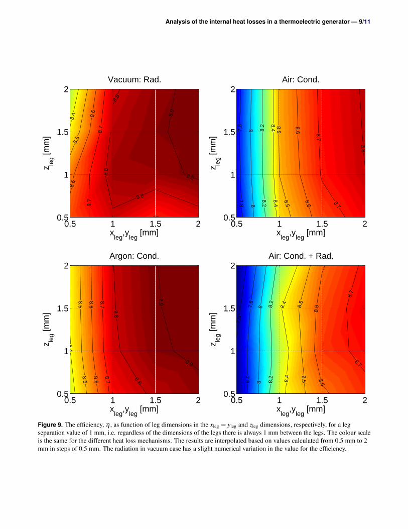
fixed cross-sectional area the efficiency remains constant.This is expected due to the adiabatic boundary conditions, aswell as the almost linear temperature profile along the legs,which means that heat loss from the leg to the air isnegligible. In the radiation case, longer legs lead to largerheat loss, as the legs have a larger surface from which toradiate heat to the cold plate. The wide legs are seen tosubstantially increase the efficiency for both the radiative andconductive heat loss cases. This is due to a smaller surface tocross-sectional area ratio, which leads to lower heat losscompared to the amount of heat flowing through the leg. Theuse of wider legs is seen to be increasingly beneficial at largerleg separations, due to the increased cross-sectional area ofthe legs compared to that of the top plate.The decrease in efficiency for longer or larger legs can beunderstood by noting that heat losses have the least effect onthe efficiency if the majority of the heat flows through thelegs and only a minor fraction bypasses the active materialvia the heat loss mechanisms. Scaling the absolute leg sizewith a factor x, increases the conduction flow through the legslinearly as the cross-sectional area increases quadratically,but the length increases linearly. However, the leg surfacearea – where the heat losses occur – scales quadratically.Thus, when up-scaling the legs, heat losses becomes moredominant. Instead, shorter legs and large cross-sectionalareas are optimal in reducing heat losses.The heat loss as function of the leg cross-sectional area,xleg = yleg, and leg length, zleg, has also been considered for afixed leg separation of 1 mm. Fig. 9 show the efficiencies ofthe module for different legs dimensions and heat lossesbased on calculated leg values of 0.5-2 mm in steps of 0.5mm. As seen in Fig. 9, increasing the legs cross-sectionalarea, (xleg,yleg) increases the efficiency of the module whilechanging the length of the legs only decreases the efficiencyin the case of radiative heat loss. This is as observed in Fig. 8.Note that, as previously mentioned, had the legs had different
Leg separation [mm]
η/η(
1x1x
1 m
m3 )
[%]
1 2 3 4 580
100
120
140
160Vacuum: Rad.Air: Cond.Air: Cond. + Rad.
1x1x2 mm3 (Long legs)
2x2x1 mm3 (Wide legs)
Figure 8. The efficiency, η , as function of leg separation forthe different heat loss cases and for different leg dimensionsnormalized with the 1×1×1 mm3 system. The argon caseconsidered in Fig. 6 is not shown, but results are in trendsimilar to the case of air.
temperature profiles due to different material properties, thelegs will start to cross-talk thermally at small separations inthe conduction case also. The ideal way to construct a TEGmodule with minimal heat losses is thus to use a goodinsulating material between the legs, properly seal themodule and using small and wide, closely spaced legs.
10. ConclusionA three dimensional numerical finite element model of athermoelectric generator consisting of p- and n-leg bismuthtelluride has been developed. The model was compared witha one dimensional numerical model for the case of no heatlosses and the results were shown to be identical. Next,different heat loss mechanisms were investigated for a closedmodule. Both surface to surface radiative heat transfer,conductive and convective heat transfer were considered, andboth separately and simultaneously. First, the influence ofsurface to surface radiation was shown to be small for the hotside temperature of 523.15 K considered here and using thesimpler surface to ambient radiation is sufficient. Second, forconductive heat transfer the efficiency as function of thermalconductivity and unicouple separation was determined. Third,heat losses due to convection inside the module were shownto be negligible for the module size considered here.Comparing the heat loss mechanisms, it was shown that foran insulator with properties similar to argon, the efficiency iscomparable to radiative heat losses. The efficiency wassignificantly lower for combined radiative and conductionheat transfer. Investigating the dimensions of the legs showedthat the ideal way to construct a TEG module with minimalheat losses is to either use a good insulating material betweenthe legs or evacuate the module completely, and use smalland wide legs closely spaced.
Analysis of the internal heat losses in a thermoelectric generator — 9/11
8.98.
9
8.8
xleg
,yleg
[mm]
Vacuum: Rad.
8.8
8.8
8.7
8.6
8.7
8.5
8.4
8.6
z leg [m
m]
0.5 1 1.5 20.5
1
1.5
2
8.8
8.7
8.7
8.6
xleg
,yleg
[mm]
Air: Cond.
8.6
8.5
8.58.4
8.4
8.2
8.2
8
8
7.8
7.8
z leg [m
m]
0.5 1 1.5 20.5
1
1.5
2
8.9
8.9
8.8
xleg
,yleg
[mm]
Argon: Cond.
8.8
8.78.7
8.68.6
8.58.5
8.4z leg [m
m]
0.5 1 1.5 20.5
1
1.5
2
8.7
8.7
8.6
8.6
8.5
xleg
,yleg
[mm]
Air: Cond. + Rad.
8.5
8.4
8.4
8.2
8.2
88
7.8
7.8
7.6
z leg [m
m]
0.5 1 1.5 20.5
1
1.5
2
Figure 9. The efficiency, η , as function of leg dimensions in the xleg = yleg and zleg dimensions, respectively, for a legseparation value of 1 mm, i.e. regardless of the dimensions of the legs there is always 1 mm between the legs. The colour scaleis the same for the different heat loss mechanisms. The results are interpolated based on values calculated from 0.5 mm to 2mm in steps of 0.5 mm. The radiation in vacuum case has a slight numerical variation in the value for the efficiency.

Analysis of the internal heat losses in a thermoelectric generator — 10/11
AcknowledgementsThe authors would like to thank the Programme Commissionfor Energy and Environment (EnMi), The Danish Researchand Innovations (Project No. 10-093971) for sponsoring theOTE-POWER research work.
ReferencesM. S. El-Genk, H. H. Saber, T. Caillat, J. Sakamoto, Tests
results and performance comparisons of coated andun-coated skutterudite based segmented unicouples, Energ.Convers. Manage. 47 (2) (2006) 174–200.
L. T. Hung, N. V. Nong, L. Han, R. Bjørk, P. H. Ngan, T. C.Holgate, S. Linderoth, B. Balke, G. J. Snyder, N. Pryds,Segmented thermoelectric oxide-based module, submittedto Energy (2014).
A. Muto, D. Kraemer, Q. Hao, Z. F. Ren, G. Chen,Thermoelectric properties and efficiency measurementsunder large temperature differences, Rev. Sci. Instrum.80 (9) (2009) 093901.
Meng, F., Chen, L., Sun, F., A numerical model andcomparative investigation of a thermoelectric generatorwith multi-irreversibilities. ENERGY 36 (5) (2011)3513–3522.
H. Kim, O. J. Kim, K. H. Lee, P. W. Heo, B. S. Choi, Finiteelement analysis of a thin-film thermoelectric module forthermal management in micro electronics. PowerMEMS2009, Washington DC, USA, December 1-4 (2009) 281.
D. Ebling, K. Bartholome, M. Bartel, M. Jagle, Modulegeometry and contact resistance of thermoelectricgenerators analyzed by multiphysics simulation, J.Electron. Mater. 39 (9) (2010) 1376–1380.
B. Jang, S. Han, J.-Y. Kim, Optimal design formicro-thermoelectric generators using finite elementanalysis. Microelectron. Eng. 88 (5) (2011) 775–778.
T. Seetawan, U. Seetawan, A. Ratchasin, S. Srichai, K.Singsoog, W. Namhongsa, C. Ruttanapun, S. Siridejachai,Analysis of thermoelectric generator by finite elementmethod. Proc. Eng. 32 (2012) 1006–1011.
Wang, X. D., Zhang, X. X., Meng, J. H., Transient modelingand dynamic characteristics of thermoelectric cooler. Appl.Energy 108 (2013) 340–348.
Huang, Y.-X., Wang, X.-D., Cheng, C.-H., Lin, D. T.-W.,Geometry optimization of thermoelectric coolers usingsimplified conjugate-gradient method. ENERGY 59 (2013)689.
Wang, X. D., Zhang, X. X., Meng, J. H., Dynamic responsecharacteristics of thermoelectric generator predicted by athree-dimensional heat-electricity coupled model. J. PowerSources 245 (2014) 262–269.
Harris, R., Shih, T.-P., Hogan, T., Schock, H., Shih, T.-P.,Heat transfer and electric current flow in a thermoelectriccouple. Collection of Technical Papers - 44th AIAAAerospace Sciences Meeting 10 (2006), 6855–6869.
M. Chen, L. A. Rosendahl, T. Condra, A three-dimensionalnumerical model of thermoelectric generators in fluidpower systems, Int. J. Heat Mass Tran. 54 (2011) 345–355.
B. Reddy, M. Barry, J. Li, Mathematical modeling andnumerical characterization of composite thermoelectricdevices, Int. J. Therm. Sci. 67 (2013) 53.
A. Bauknecht, T. Steinert, C. Spengler, G. Suck, Analysis ofannular thermoelectric couples with nonuniformtemperature distribution by means of 3-d multiphysicssimulation, J. Electron. Mater. 42 (7) (2013) 1641–1646.
T. Yang, J. Xiao, P. Li, P. Zhai, Q. Zhang, Simulation andoptimization for system integration of a solarthermoelectric device. J. Electron. Mater. 40 (5) (2011)967–973.
Wang, X.-D., Huang, Y.-X., Cheng, C.-H., Lin, D. T.-W.,Kang, C.-H., A three-dimensional numerical modeling ofthermoelectric device with consideration of coupling oftemperature field and electric potential field. ENERGY47 (1) (2012) 488–497.
H. H. Saber, M. S. El-Genk, A three-dimensional,performance model of segmented thermoelectricconverters. AIP Conf. Proc. 608 (1) (2002) 998.
P. Ziolkowski, P. Poinas, J. Leszczynski, G. Karpinski, E.Muller, Estimation of thermoelectric generatorperformance by finite element modeling. J. Electron. Mater.39 (9) (2010) 1934–1943.
Comsol Multiphysics, A., 2013. Tegnergatan 23, SE-111 40Stockholm, Sweden.
Y. Yang, S. H. Xie, F. Y. Ma, J. Y. Li, On the effectivethermoelectric properties of layered heterogeneousmedium, J. Appl. Phys. 111 (1) (2012) 013510.
Y. Ma, Q. Hao, B. Poudel, Y. Lan, B. Yu, D. Wang, G. Chen,Z. Ren, Enhanced thermoelectric figure-of-merit in p-typenanostructured bismuth antimony tellurium alloys madefrom elemental chunks. Nano Lett. 8 (8) (2008)2580–2584.
C. Kim, D. H. Kim, H. Kim, J. S. Chung, Significantenhancement in the thermoelectric performance of abismuth telluride nanocompound through brief fabricationprocedures. ACS Appl. Mater. Interfaces 4 (6) (2012)2949–2954.
G. J. Snyder, T. S. Ursell, Thermoelectric efficiency andcompatibility. Phy. Rev. Lett. 91 (14) (2003) 148301.
Analysis of the internal heat losses in a thermoelectric generator — 11/11
D. M. Rowe (Ed.), Thermoelectrics Handbook - Macro ToNano. Taylor and Francis Group, LLC, 2006.
G. Fraisse, J. Ramousse, D. Sgorlon, C. Goupil, Comparisonof different modeling approaches for thermoelectricelements, Energ. Convers. Manage. 65 (2013) 351–356.
Marlow Industries, Inc, 2013. Private communication.
Lemmon, E., Jacobsen, R., Penoncello, S., Friend, D., 2000.Thermodynamic properties of air and mixtures of nitrogen,argon, and oxygen from 60 to 2000 K at pressures to 2000MPa. J.Phys.Chem. Ref. Data 29 (3).