ANALYSIS OF SPHERICAL TEXTURE ON CHARACTERISTICS OF HYDRODYNAMIC JOURNAL...
70
ANALYSIS OF SPHERICAL TEXTURE ON CHARACTERISTICS OF HYDRODYNAMIC JOURNAL BERAING A Thesis Submitted in Partial Fulfillment of the Requirements for the Award of the Degree of Master of Technology in Mechanical Engineering (Machine Design & Analysis) By Himalaya Dawani Roll No.213ME1376 Under the Supervision of Prof. Suraj Kumar Behera NATIONAL INSTITUTE OF TECHNOLOGY ROURKELA
-
Upload
trankhuong -
Category
Documents
-
view
226 -
download
4
Transcript of ANALYSIS OF SPHERICAL TEXTURE ON CHARACTERISTICS OF HYDRODYNAMIC JOURNAL...

ANALYSIS OF SPHERICAL TEXTURE ON
CHARACTERISTICS OF HYDRODYNAMIC
JOURNAL BERAING
A Thesis Submitted in Partial Fulfillment of the Requirements for the
Award of the Degree of
Master of Technology
in
Mechanical Engineering
(Machine Design & Analysis) By
Himalaya Dawani Roll No.213ME1376
Under the Supervision of
Prof. Suraj Kumar Behera
NATIONAL INSTITUTE OF TECHNOLOGY ROURKELA

National Institute of Technology Rourkela
Certificate
This is to certify that the thesis entitled, “Analysis of spherical texture on
characteristics of hydrodynamic journal bearing” submitted by Mr. Himalaya
Dawani to National Institute of Technology Rourkela, during the academic session
2013-2015 is a record of bonafide research work carried out by him under my
supervision and is worthy of consideration for the award of the degree of Masters
of Technology in Mechanical Engineering with specialization in Machine Design
and Analysis. The embodiment of this thesis has not been submitted to any Other
University and/or Institute for the award of any degree or diploma.
\
Date: 2nd Jun, 2015
Prof. Suraj Kumar Behera
Dept. of Mechanical Engineering
National Institute of Technology
Rourkela-769008
DEPARTMENT OF MECHANICAL ENGINEERING
NATIONAL INSTITUTE OF TECHNOLOGY
ROURKELA 769008
ACKNOWLEDGEMENT
It gives me immense pleasure to express my deep sense of gratitude to my
supervisor Prof. Suraj Kumar Behera for his invaluable guidance, motivation,
constant inspiration and above all for his ever co-operating attitude that enabled
me in bringing up this thesis in the present form.
I am thankful to Prof. S. S. Mohapatra, Head, Department of Mechanical Engineering
for providing all kinds of possible help and advice during the Course of this work.
I would like to thank Mr. Pravajyoti patra M.Tech scholar, Department of
Mechanical Engineering for his valuable suggestion during the research work. I am
greatly thankful to all the staff members of the department and all my well-
wishers, class mates and friends for their inspiration and help.
I would like to thanks my parents for their unconditional support, love and
affection. Their encouragement and never ending kindness made everything easier
to achieve.

i | P a g e
Abstract
Texture produced on the surface of hydrodynamic journal bearing have certain changes in the
coefficient of friction, load carrying capacity, wear rate, stiffness and damping of the two
surfaces which are matting with each other. By creating texture or micro dimple on a
hydrodynamic journal bearing, pressure increases and significant improvement has been
achieved in its load carrying capacity, lubricant flow rate, coefficient of friction etc. In a present
work numerical analysis has been carried out to determine the effect of using negative spherical
surface texture on hydrodynamic journal bearing surface and it is compared with normal journal
bearing i.e. journal bearing without texture. We can take any other profile also but spherical
profile is easy to fabricate by laser technology or etching process. The Reynolds equation is
solved numerically with the help of central finite difference method and analysis is done on the
effect of texture height, asperity ratio and number of textures on the journal bearing. Here we
also determine the behavior of parameters of hydrodynamic journal bearing (texture and without
texture) with increase in eccentricity ratio. Texture journal bearing has a great importance in
journal bearing because in vertical journal bearing initially it provides converging part which
helps in increasing load carrying capacity which is not present in plain journal bearing. The
author believes that such detail analysis of texture on journal bearing surface to study different
tribological behavior under different condition will help researchers around the world.

ii | P a g e
CONTENTS
TITLE PAGE.NO
Abstract i
Contents ii
List of Figures iv
Nomenclature vi
1 INTRODUCTION
1.1: Background 1
1.2: Thesis overview 2
1.3: Objective of the Project 2
1.4: Basic Concepts 4
1.4.1: Surface topography 4
1.4.2: Friction 5
1.4.3: Wear 6
1.4.4: Lubrication 7
1.5: Fluid Film Lubrication 8
1.6: Design 9
1.6.1: Integral 10
1.6.2: Bushing 10

iii | P a g e
1.6.3: Two piece 11
1.7: Surface texturing 12
1.7.1: Deterministic asperities 13
2 LITERATURE REVIEW 16
3 NUMERICAL ANALYSIS 20-36
4 RESULT AND DISCUSSIONS 37
5 CONCLUSION AND FUTURE SCOPE 54
5.1: Conclusion 54
5.2: Future scope 55
6. References 56

iv | P a g e
LIST OF FIGURES
Fig.No Title Page. No
Figure 1.1: Surface topography 4
Figure 1.2: Square positive asperity 14
Figure 1.3: Cylindical positive asperity 14
Figure 1.4: Square Negative Asperity 15
Figure 1.5: Cylindrical Negative Asperity 15
Figure 3.1: Infinitesimal element in Equilibrium 21
Figure 4.1: Modelling with different aspect ratio and texture height ratio 37
Figure 4.2: Modelling with different aspect ratio and texture height ratio 38
Figure 4.3: Textured bearing 38
Figure 4.4: Zoomed micro asperities on journal bearing surface 38
Figure 4.5: Single positive asperity 39
Figure 4.6: Distributed positive asperity 39
Figure 4.7: Single negative asperity 39
Figure 4.8: Distributed negative asperity 39
Figure 4.9: Pressure profile of normal journal bearing 40
Figure 4.10: Pressure profile of texture journal bearing 40
Figure 4.11: Eccentricity ratio vs Non dimensional load 42
Figure 4.12: Eccentricity ratio vs Friction parameter 43
Figure 4.13: Eccentricity ratio vs Non dimensional flow rate 44
Figure 4.14: Eccentricity ratio vs Stiffness coefficient (normal bearing) 45

v | P a g e
Figure 4.15: Eccentricity ratio vs Stiffness coefficients (textured bearing) 46
Figure 4.16: Eccentricity ratio vs Damping coefficient (normal bearing) 47
Figure 4.17: Eccentricity ratio vs Damping coefficients (textured bearing) 48
Figure 4.18: Asperity ratio vs Non dimensional load 49
Figure 4.19: Aspect ratio vs Coefficient of friction parameter 50
Figure 4.20: Texture height vs Non dimensional load 51
Figure 4.21: Texture height vs Coefficient of friction parameter 52

vi | P a g e
Nomenclature
ρ: Density of lubricant (Kg/m3)
η or : Dynamic viscosity of lubricant (N-sec/m2)
h: Lubricant film thickness (mm)
�̅� : Non-dimensional film thickness = h
c
z
zL
C: Clearance (mm)
Cg: Texture height (mm)
𝑪𝒈̅̅ ̅̅ : Non-dimensional texture height
R: Radius of bearing (mm)
r: Radius of journal (mm)
�̅� : Non-dimensional co-ordinates
�̅� : Non-dimensional load = 2
2
W
u R L
c
�̅�: Non-dimensional flow = 3
q
c
�̅� : Non-dimensional frictional force =F
uRL
c
�̅�: Non-dimensional co-efficient of friction = /F W
�̅�: Non-dimensional pressure = 2
26
pc
R
THR: Texture height ratio
vii | P a g e
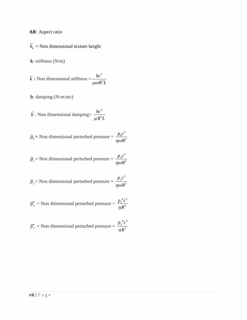
AR: Aspect ratio
bh = Non dimensional texture height
k: stiffness (N/m)
k : Non dimensional stiffness =2
3
kc
R L
b: damping (N-m/sec)
b : Non dimensional damping= 3
3
bc
R L
0p = Non dimensional perturbed pressure = 2
0
2
p c
R
xp = Non dimensional perturbed pressure = 3
2
xp c
R
yp = Non dimensional perturbed pressure =
3
2
yp c
R
xp = Non dimensional perturbed pressure = 3
2
xp c
R
yp = Non dimensional perturbed pressure =
3
2
yp c
R

1 | P a g e
Chapter 1
Introduction
1.1 Background
Tribology is the branch of science which deals the surfaces, that are rub together or we can say
that it is a scientific and systematic method to deal with interacting surfaces so that
characteristics of the system can be improved. Tribology contains the study of chemistry, physics
and mechanics of rubbing surfaces which include friction wear and lubrication of materials.
From the ancient civilization various attempts have been made to minimize friction and wear so
that we can transport men and materials from one place to another place in an economical way.
This was the biggest challenge faced from past till now. In the nineteenth and the twentieth
century lubrication came into picture which is usually put between interacting surfaces to
minimize friction and wear.
Tower (1883) [1] who was a railroad engineer at that time has done a series of experiments on
lubrication so that he could minimize friction to control the wear, for this he drilled a hole in a
bearing so that lubricant (oil) can be poured through it, when shaft starts rotating he observes that
the oil is coming out of that hole, to prevent this he put a plug on that hole. However, he noticed
that plug is been thrown out from that hole, from there he concluded that oil film is being formed
in between shaft and bearing that generates sufficiently high pressure to through the plug out of
the hole. At the same time Petroff (1883) [2] was interested in calculating friction in journal
bearings. For this he conducted some experiments and came out with some relationship between
frictional force and operating parameters of bearing. However, he didn’t notice that the oil film
also generates the pressure which was given by tower hence he should be given the credit for

2 | P a g e
enhancing the concept of hydrodynamic fluid film lubrication. With the help of these
developments, Reynolds (1886) [3] formulated the concept of formation of hydrodynamic fluid
film lubrication in journal bearings and developed Reynolds equation for hydrodynamic
lubrication. Reynolds equation also explained that hydrodynamic pressure which is generated
between shaft and bearing is due to converging wedge shaped film, viscosity of oil and surface
motion. It was also suggested by him that both pressure gradient and pressure for divergent
portion will be zero at the film rupture boundary. The results gave by Reynolds were
approximate as he didn’t go for the integration of Reynolds equation. Sommerfield (1904) [4]
obtained the analytical expression for pressure distribution, load carrying capacity, frictional
force etc. by integrating the Reynolds equation. These equations form a basis later to design
different types of bearings which was later used in different machineries. After these
developments Kingsbury (1913) [5] developed gas bearing and showed that air film can also be
used to carry load.
Current research target to modify the surface of journal by introducing texture on it and a detail
study was done to find non dimensional pressure profile, non-dimensional load carrying
capacity, coefficient of friction parameter, stiffness and damping coefficients by varying
eccentricity ratio, asperity ratio and texture height.
1.2 Thesis overview
Creating surface texture or micro asperity or undulation on the surface the surface of mechanical
component produces more wedging action as compared to the normal i.e. without textured
bearing which will results in increase in pressure due to which there will be increase in load

3 | P a g e
carrying capacity, it also reduces friction because each undulation will act as a reservoir, stores
lubricant and will provide it during starving condition. Micro asperities or texture can be of
different shapes such as cylindrical, elliptical, spherical, circular, semi spherical and various
others but we have done work using spherical micro asperity and it can be of different sizes also,
so an optimum size should be used. Here we have done a theoretical analysis on hydrodynamic
journal bearing by applying texture on it and find its effect on tribological parameters of
hydrodynamic journal bearing.
1.3 Objectives of present work
In present research work we study how negative spherical micro asperities affect the properties
of journal bearing. Following are the main objectives of present work:
a. Development of numerical solution to determine the effect of negative spherical micro
asperity on hydrodynamic journal bearing.
b. Analysis is done by varying epsilon, asperity ratio, and texture height.
c. Comparison of tribological parameters for plain and textured journal bearing on varying
eccentricity ratio, asperity ratio and texture height.

4 | P a g e
1.4 Basic concepts
1.4.1 Surface topography
Fig 1.1: Surface topography ( www.ptu.tu-darmstadt.de)
Usually due to mating surfaces tribological phenomenon occurs, so the variation in the surface
texture is the key point for studying the mechanism of friction and wear. The imperfections at the
surface at a nano level are measured and compared by macroscopic deviations from flatness. In
general we consider all the surfaces to be rough except cleaved faces of mica. Roughness means
peaks and valleys on the most part of the surfaces. The rough surface profile is always random
unless and until some deliberately rough structures are made on it.
Most of the real engineering surfaces generally consist of random and non random features. The
prime example of non random topological characteristics is a series of grooves formed by a
shaper on a metal surface. The shaped surfaces also give rough texture because it also contains
5 | P a g e
high degree of random surface features.
These micro asperity or undulations have various shape and sizes. Their heights vary from
fraction of a nanometer to several millimeters. Depending on the scale, they can be called macro
deviations, roughness or waviness. Macro deviations are mainly recognized by asperities of
small height with gentle slopes similarly for waviness the ratio of distance between asperities to
asperity height is more than 40.
1.4.2 Friction
In many types of machinery rough surfaces generally rub against each other under an
unlubricated environment which results in high friction and lubrication. Leonardo da Vinci
(1452-1519) [6], Coulomb (1785) [7], Amonton (1699) [8] enunciates the fundamental laws of
friction which are
i. Frictional force varies with the normal load.
ii. The force of friction is independent of the contact area.
iii. Static friction is much larger as compared to kinetic friction.
iv. Friction doesn’t depend on the sliding velocity.
When the shaft rotates inside the bearing generally interlocking of asperities takes place due to
which resistance to relative motion occurs which is the main cause of friction between two
surfaces. Molecular attraction as the main reason for friction between two interacting surfaces is
proposed by Hardy (1936) [9]. Bowen and Tabor (1950) [10] also proposed the theory in which
the theory of cold welding, shearing, ploughing of the soft metal by hard asperities are the main
reasons of friction. Tomlinson (1929) also gave the molecular attraction theory in which he

6 | P a g e
attributed frictional resistance to rupture of molecular bond between the two surfaces which are
interacting with each other. For metal to metal contacts Bowen and Tabor theory is widely
accepted and for polymer molecular bond rupture theory is widely used.
1.4.3 Wear
Wear can be defined as a removal of material from one of the surface of a body (which are
interacting with each other) occurring as a result of relative motion at the surface. Generally
tribological pairs are supplied with lubricant so as to avoid the excessive wear and damage which
would be present if two surfaces interacted with each other in dry state, to reduce their frictional
resistance to motion. The economic consequences of wear are many more such as-:
Cost of replacement of parts
Cost involved in machine downtime
Loss of production.
The wear rate of rolling or sliding contact is often defined as the volume which is lost due to
wearing of surface per sliding distances. For particular dry or unlubricated sliding situation the
wear rate depends on various factors such as –:
I. Normal load,
II. Relative sliding speed,
III. Initial temperature
IV. Thermal, mechanical and chemical properties of the materials in contact.
7 | P a g e
1.4.4 LUBRICATION
There are various lubrication system types which are classified as [11]-:
Class I — Bearings in which lubricant is provided from an external source (e.g., oil, grease,
etc.).
Class II — Bearings which have lubricant inside the walls of the bearing (e.g., graphite, bronze,
etc.). Generally these bearings required lubricant from outside for achieving maximum
performance.
Class III — Bearings in which materials of bearing is similar to that of lubricant. These are also
known as “self-lubricating” and don’t require external lubricant.
Plastic bearings and oilites made from polyacetal are the examples of second type of bearing;
metalized graphite bearings and PTFE bearings [11] are the examples of third type of bearings.
Plain bearings have plain inner surface, some of them are grooved which helps the lubrication in
entering the bearing to cover the whole journal [12].
Bearings which have lubricant enclosed within the bearing walls are known as self-lubricated
bearings. These are of many types. Bearings having porous walls are the first type of self-
lubricated bearings which is known as sintered metal bearings. These porous walls use capillary
action to draw oil [13] and discharges when heat or pressure is applied [14], for e.g. in self-
lubricating chains. Second one is a solid one-piece metal bushing having a figure eight groove
channel on the inner diameter which is filled with graphite, eight groove channel is there so that
bearing can be lubricated inside and out [15] and its final form is a plastic bearing, in which
lubricant is shaped into the bearing. The lubricant is discharged as the bearing is run in [16].
Types of lubrication can be classified as:
8 | P a g e
I. Boundary condition.
II. Full film condition.
III. Dry condition.
1.5 Fluid lubrication
Fluid lubrication results in a boundary or full film lubricant mode condition. It can be lubricated
in two ways i.e. hydro statically or hydro dynamically lubricated. Hydrostatically lubricated
bearings are those bearing which use external pump to lubricate the bearing and constantly
generate static pressure whereas the bearing which keeps the pressure in the oil film by the
rotation of the journal is known as hydro dynamically lubricated journal bearing. State of
hydrostatic bearings changes in to hydrodynamic state during rotation of journal [17]. Mostly oil
is used by hydrostatic bearing whereas hydrodynamic bearing can use grease or oil.
"Oil whirl" is the disadvantage in high speed machinery in fluid lubricated bearing. The main
reason of oil whirl occurrence is lack of stability in lubrication wedge, small disturbance in the
journal cause reaction forces from the oil film which results in further movement, causing both
the oil film and journal to "whirl". Generally the frequency of whirl is about 42% of the turning
speed of journal. In worst cases oil whirl may cause the direct contact between the journal and
the bearing, due to which bearing wears out rapidly. In some of the cases the frequency of whirl
matches with the natural frequency this leads to catastrophic failure [17, 18] and it is very
destructive.
This can be prevented by a stabilizing force which is applied to the journal. There are number of
bearing designs which used bearing geometry to either provide an obstruction in the way of

9 | P a g e
whirling fluid or to provide a stabilizing load so as whirl can be minimize. One such is called
the elliptical bore or lemon bore. In this design, shims are installed between the two halves of the
bearing housing and then the bore is machined to size. After the removal of shims, the bore
resembles a lemon shape, which reduces the clearance in one direction of the bore and increases
the pre-load in that direction. The main disadvantage of this design is its lower load carrying
capacity, in comparison to typical journal bearings. It is also still capable to oil whirl at high
speeds, however its cost is relatively low [17].
Another design is the pressure dam or dammed groove [19] which has a deep relief cut in the
center of the bearing over the top half of the bearing. The groove suddenly stops in order to
create a downward force to balance the journal. Design has a high load capacity and rectifies
most oil whirl situations. The disadvantage is that it works only in one direction. Offsetting the
bearing halves have the same effect as the pressure dam. The only difference is that the load
capacity increases as the offset increases [17].
A more ultra-design is the tilting pad design, which utilizes multiple pads that are designed to
move with loads which changes frequently. It is mostly used in very large applications such as
modern turbo machinery because it almost completely cancels out oil whirl and saves the bearing
from catastrophic failure.
1.6 DESIGN
The design of a bearing mainly depends on the type of motion which the bearing is provided.
The three types of motions which are possible are:

10 | P a g e
Journal (friction, radial or rotary) bearing: It is a type of plain bearing; this type of bearing
usually consist of a shaft rotating in a bearing [20] for e.g. in rail road car and
locomotive applications a journal bearing specifically focus to the plain bearing once used at the
ends of the axles of railroad wheel sets, enclosed by journal boxes [21].
Linear bearing: This type of bearing provides linear motion; it can take the form of a circular
bearing and shaft or any other two similar surfaces (e.g., a slide plate) [20].
Thrust bearing: This bearing provides a bearing surface for forces acting axial to the shaft [3].
1.6.1 Integral
Integral plain bearings are developed into the object of use. It is a hole which has been prepared
into a bearing surface. The materials used in this type of bearing are Babbitt or cast iron and a
hardened steel shaft [21].
These bearings are not as common because in these types of bearings, bushings are easy to adjust
and it can be replaced if necessary [20]. Looking with respect to material, an integral bearing
may be lesser in cost but it cannot be replaced, if it wears out. If wearing occurs, then the item
may be replaced or reworked for e.g. hinge, which is usually in both thrust bearing and a journal
bearing.
1.6.2 Bushing
An independent plain bearing which is inserted into a housing so that it give a bearing surface for
rotary applications is known as bushing, it is also known as a bush; and also the most common
form of a plain bearing [22]. There are carious design of bushings which include sleeve, split,
and clenched bushings. A sleeve, split, or clenched bushing is only a "sleeve" of material with an
inner diameter (ID), outer diameter (OD), and length. These three bushing are different in a way

11 | P a g e
that a solid sleeved bushing is solid whole way around, a split bushing has a cut along its length,
and a clenched bearing similar like the split bushing but with a clench across the cut. A flanged
bushing known as sleeve bushing consists of a flange at one end which is extending radially
outward from the outer diameter. Flange is used to position the bushing when it is installed or to
provide a thrust bearing surface [23].
1.6.3 Two-piece
Two-piece plain bearings or full bearings are mainly used in industrial machinery [24], these are
mainly used for larger diameters, for e.g. in crankshaft bearings. Two-piece plain bearings
contain two half which are called shells [25]. To keep the shells positioned various systems are
used. The method which is mostly used is a notch in the housing tab that matches with the
parting line edge to restrain axial movement after installation. For shells which are large, thick
button stop or dowel pin is used. The button stop is coupled to the housing, while the dowel pin
keys the two shells together. Another method which is not generally uses a dowel pin that keys
the shell to the housing through a slot or hole in the shell [26].
The distance between one parting edge and the other is larger than the corresponding distance in
the housing so that pressure which is required should be small which keeps the bearing in place
as the two halves of the housing are installed. Finally, the housing circumference is also merely
smaller than the shell's circumference so that the bearing crushes lightly when the two halves are
bolted together. Due to this large amount of radial force around the entire bearing will be
developed, which keeps it spinning. It also forms a better interface for heat to travel in to the
housing from bearing [25].

12 | P a g e
1.7 SURFACE TEXTURING
Surface texturing is a technique by which micro dimples or undulation or asperity is created on
the surface of materials which improve tribological properties such as load carrying capacity,
wear resistance, friction resistance etc. of the material [27]. These undulations or micro dimples
act as a reservoir which feed the lubricant to contact surfaces during starved conditions reduces
the friction and wear. If the surface is mostly rough then wear will develop quickly, however if
most of the surface smooth, inadequate lubrication or seizure may occur.
Different types and shapes of grooves can be produced by various techniques which are-
I. Lithography technique
II. Etching of silicon wafer
III. Mechanical indentation
IV. Laser surface texturing
V. Abrasive jet machining
VI. Novel dressing technique
From above all techniques, laser surface texturing technique is generally used because of its
cleanliness to environment and provides outstanding control on the properties of micro-dimple. It
is known that friction and wear create losses but efficiency and lifespan can be extensively
improved by using laser surface texturing.
Laser surface texturing mainly have three functions-:
Micro hydrodynamic bearing-: During relative motion between two contact surfaces
each micro dimple acts as a small hydrodynamic bearing. This hydrodynamic effect
results from the pressure gradient which forms in each cavity. Shear forces acting on a

13 | P a g e
lubricant at the surfaces due to relative motion between two contact surfaces, which
results in wedge formation and due to wedge formation pressure profile is developed.
This type of bearing reduces friction and wear. For micro hydrodynamic bearing
lubrication is necessary.
Lubricant reservoirs-: Micro dimple act as a reservoir of lubricant which will feed
lubricant to the contact surfaces whenever starved condition arises due to which friction
and wear decreases which prolonged the life span of the material. Since these micro
reservoirs exist as asperities or micro dimples on the surface of bearing, so the geometry
and pattern of micro dimple must be closed so as to prevent the force flow of lubricant
out of channel.
Debris trap-: Micro dimple provide the space for debris to fit in to it and reduce the
abrasive wear which was earlier taking place in contact zone.
1.7.1 Deterministic Asperities
Micro asperities or undulation are the small dimples on a surface of the metals that creates
surface roughness. Deterministic micro asperities are the asperities of definite shape, size, and
orientation. Macro asperities have specific surface features with very low height to diameter
(aspect ratio) <0.0001. Macro asperities are mostly few in numbers which are created on the
surface of bearing with comparative ease by using various processes such as laser itching and
grinding. Similarly deterministic micro asperities are smaller in average diameter, significantly
large in number with larger aspect ratio. There are various methods to fabricate such asperities
such as photo etching, laser texturing, LIGA process (German acronym for lithography,
electroplating & molding) & UV photo lithography process. Modified LIGA process has UV
light as a substitute for X-ray. Surface texturing concept was developed after 1990 using
14 | P a g e
primarily laser technology. This process found a large number of industrial applications like in
case of mechanical seals this technology enhances axial stiffness. Surface texturing technique is
an efficient technique in tribology field because it reduces friction coefficient, wear rate and
increases load capacity without changing dynamic stiffness and damping coefficient.
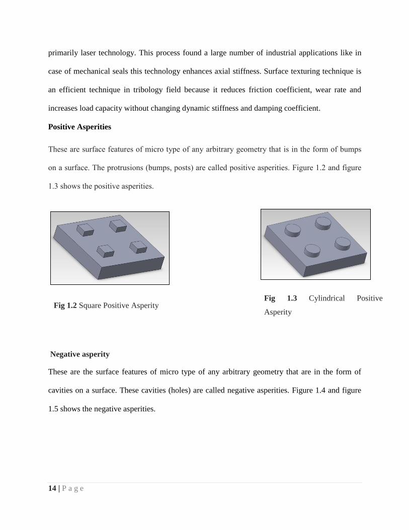
Positive Asperities
These are surface features of micro type of any arbitrary geometry that is in the form of bumps
on a surface. The protrusions (bumps, posts) are called positive asperities. Figure 1.2 and figure
1.3 shows the positive asperities.
Negative asperities
Negative asperity
These are the surface features of micro type of any arbitrary geometry that are in the form of
cavities on a surface. These cavities (holes) are called negative asperities. Figure 1.4 and figure
1.5 shows the negative asperities.
Fig 1.2 Square Positive Asperity Fig 1.3 Cylindrical Positive
Asperity

15 | P a g e
Fig 1.4 Square Negative Asperity Fig 1.5 Cylindrical Negative Asperity
(a)-: We can produce both positive and negative dimples of various cross section and shape with
the help of Lithography technique.
(b)-: Only way of producing spherical or conical geometry is by laser texturing method.

16 | P a g e
Chapter 2
Literature survey
Considerable amount work has been done on the surface texture on hydrodynamic journal
bearing but still a lot of work has to be done further. This chapter contains a list of works which
have already been done in the past on the texture profile journal bearing which helps in
understanding various aspects of the surface texture journal bearing and study the performance
parameter.
It is now easy to improve the tribological performance by surface texturing technique, which
includes decrease in friction parameter, increases life, load capacity and lowers the energy
consumed by producing the micro dimples on bearing surface. The technology of surface
texturing is expected to be a very sufficient in future because it improves tribological properties
of component as demonstrated by Priest [28].
Surface texture improves the tribological properties of boundary lubricated sliding surfaces. By
producing micro dimples or asperities on the surface, we can improve the tribological properties
of the component. After then lubricant is supplied inside the system with the help of small
reservoirs, so as to reduce friction and increase lifetime of the system.
There are various situations of tribological contact in which improvement in characteristics has
been seen by texturing such as in lubricated mechanical components e.g. aerodynamically
lubricated magnetic hard disks, honed cylinder surfaces
Petterson and Jacobson [29] in 2003 determine the behavior of wear and friction properties of
boundary lubricated textured surfaces. In this they determine how lubricant can be supplied to
the interface and how to separate wear particles according to their sizes, shapes and orientation.

17 | P a g e
Series of surface textures of parallel grooves or square depression of various characteristics have
been produced by various techniques such as anisotropic etching of silicon wafers and
lithography.
Wakuda et al. [30] experimentally found that tribological characteristics of any system mainly
relies on the size and density of micro dimples, and have very little effect of shape .
According to Siripuram et al. [31] there are various types of shapes of microstructures such as
spherical, cylindrical, hemi spherical, triangular cross-section, square etc. and according to his
experimental results square asperities gives the largest leakage rate and triangular asperities gives
the smaller leakage rate.
Kovalchenko et al. [32] have studied laser texturing expanded the contact parameters in terms of
speed and load of hydrodynamic lubrication. Laser surface texturing technique is more efficient
at higher loads and speed provided that viscosity of lubricant should be high.
Mehenny et al. [33] had done a theoretical analysis to determine the influence of circumferential
waviness of the journal in automotive engine on the lubrication of bearing. Assumption was
made that surfaces of bearing and shafts have to be rigid and lubricant isoviscous.
Ronen et al. [34] provided the way to improve the tribological characteristics of the reciprocating
automotive components by studying the micro-surface structure in the form of micro pores. He
found that surface texturing on the surface of system can be used effectively to maintain
hydrodynamic effects even with nominally parallel surface, and the optimum surface texturing
improves the tribological characteristics in reciprocating automotive components.
18 | P a g e
Brizmer [35] demonstrated the use of laser surface texturing in parallel thrust bearing. It is found
that the characteristics of textures may affect characteristics of bearing. The effects of texturing
will be positive and it will improve the performances of journal bearing.
Values of friction torque, maximum pressure, minimum film thickness, axial film flow, and
rupture film angle for both the surfaces (smooth and textured) are compared for different texture
area fraction δ2. The following results are obtained-:
With the increase in area of dimples, frictional torque will decrease for textured
surface, whereas for smooth surface it will remain constant throughout.
Maximum pressure will decrease with increase in surface area for textured
surface, whereas for smooth area it will remain constant.
Minimum film thickness increases with increase in area of dimples for textured
surface, whereas for smooth surface it will remain constant.
Axial film flow will decrease with area for textured surface whereas for smooth
surface it will remain constant.
Rupture film angle will increase with increase in area for textured surface,
whereas it remains constant for smooth surface.
Friction torque, maximum pressure, minimum film thickness, axial film flow and rupture film
angle are dissimilar from corresponding values which involve smooth surface. Difference
becomes much larger as we increase texture area fraction.
Christensen [36], Tonder [37], Elrod [38], and Patir and Cheng [39] established the theories for
hydrodynamic lubrication of rough surfaces. Surfaces of material can have different texture
positions because of running-in and machining process. Christensen's concept [36] was extended

19 | P a g e
to the two sided roughness cases by Rhow and Elrod [40], Prakash [41], Z hang and Qiu [42, 43].
The averaged flow model of Patir and Cheng [44] was used by Boedo and Booker [45] for the
analysis of isotropic Gaussian surface roughness effects in engine bearings. Christensen's
stochastic model [36] was used by the Zhang and Qiu [42, 43] for determining the engine
bearings effects of two-sided roughness with three types of roughness texture, in which the effect
of transverse roughness only concerned the dimensionless bearing parameters.
The nominal minimum film thickness constantly decreases by the isotropic roughness. Minimum
film thickness was negligibly affected by the transverse roughness. Increase in maximum film
pressure is constantly seen due to transverse roughness, while decreases in nominal minimum
film thickness is seen due to longitudinal roughness and both the roughness’s increase or
decrease the maximum film pressure is closely related to characteristics of nominal geometry
and operating factors.
Asymmetric pressure distribution in the dimple area provides extra hydrodynamic pressure to
separate the surface, due to inertia of lubricant. According to Tonder [37], if series of micro
dimples are produced at the starting of sliding surface, it will generate extra pressure and will
support higher load. Brizmer et al. [46] concluded that partial texturing generates collective
dimple effect which results in pressure distribution over textured zone. Etsion and coworkers
[47] concluded that dimple depth is most important factor for load generation. According to Yu
and Sadeghi [48] there is some optimum value at which bearing can take maximum load. Sachlin
et al. [49] states that maximum load is achieved when recirculation occurs at certain groove
depth. According to Arghir et al. [63] if we analyze a single cell having micro dimple showed
that, anti-symmetrical profile is induced due to inertia effects which results in positive load on
the upper sliding surface.

20 | P a g e
Chapter 3
Theoretical and numerical analysis
Generalized fluid equation & Reynolds’s equation-:
The equations used for the generalized journal bearing is derived from the simplification to the
general fluid mechanic equations governing the conservation of mass (continuity equation),
momentum (Navier-Stokes equations), and energy (energy equation). The theory of
hydrodynamic bearing on a differential equation was derived by Osborne Reynold. From
Reynolds’ theory we get the mechanism of lubrication through the generation of a viscous liquid
film between two interacting surfaces. There are two conditions for the occurrence of
hydrodynamic lubrication.
There must be relative motion between two interacting surfaces with velocity which is
sufficient for a load carrying lubricating film to be generated.
Surfaces which are interacting must be inclined at some angle to each other, i.e. if they
are parallel, pressure field will not be formed in the lubricating film and required load
can’t be supported.
Reynolds’s equation is based on the following assumptions:
Newton’s law of viscosity must be obeyed by lubricant.
The lubricant incompressible.
The inertia forces of oil film are negligible.
Lubricant should be of constant viscosity.
21 | P a g e
The effect of curvature of the film with respect to film thickness is neglected.
Assumption is already made that the film is so thin that the pressure is constant across the
film thickness.
Lubricant should be constantly supplied.
There is no slip at the boundary.
The shaft and bearing are rigid.
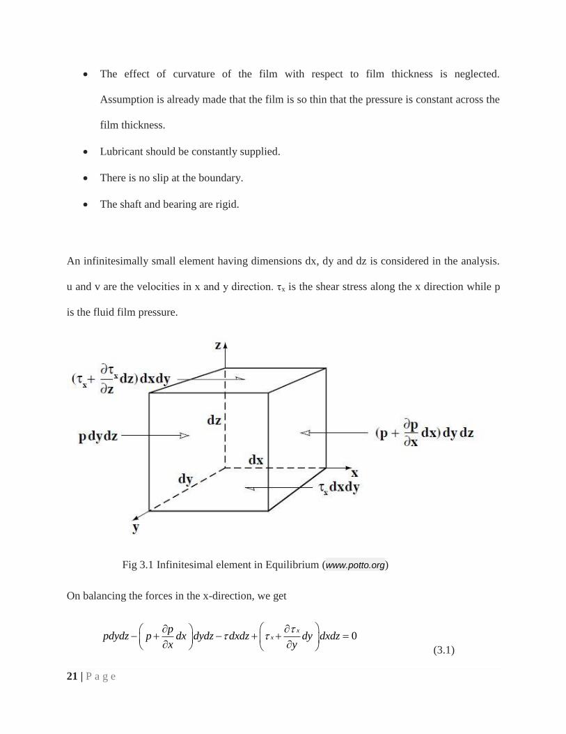
An infinitesimally small element having dimensions dx, dy and dz is considered in the analysis.
u and v are the velocities in x and y direction. τx is the shear stress along the x direction while p
is the fluid film pressure.
Fig 3.1 Infinitesimal element in Equilibrium (www.potto.org)
On balancing the forces in the x-direction, we get
0x
xp
pdydz p dx dydz dxdz dy dxdzx y
(3.1)

22 | P a g e
xp
x z
( Assuming dx, dy, dz 0) (3.2)
From Newton’s law of viscosity we know that
xdu
dz (3.3)
Substituting (3.3) into (3.2) we get
2
2
P u
x z
(3.4)
Similarly balancing the forces in the y- direction, final result will be
2
2
P v
y z
(3.5)
And in z- direction (assumption)
0p
z
(3.6)
As mention in the above assumption that, there is no slip or velocity at the boundary of the
wedge, the boundary conditions are:
u = U2 at z = 0
u = U1 at z = h
Integrating twice the equation (3.4) and (3.5) we will find he value of velocities “u and v” as
2
1 2 22
z zh p zu U U U
x h
(3.7)
23 | P a g e
2
1 2 22
z zh p zv V V V
y h
(3.8)
Taking the equation of continuity
0u v w
t x y z
(3.9)
Integrating the above equation from 0 to h
0 0 0 0
0h h h h
dz u dz v dz w dzt x y z
(3.10)
Applying Leibnitz integration rule i.e.
, ,u d d
dz udz u x u xx x dx dx
Putting the value of ‘u’ and ‘v’ from equation (3.7) and (3.8) and applying at equation (3.10) a
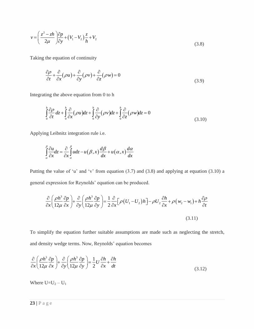
general expression for Reynolds’ equation can be produced.
3 3
1 2 2 2 1
1
12 12 2
h p h p hU U h U w w h
x x y y x x t
(3.11)
To simplify the equation further suitable assumptions are made such as neglecting the stretch,
and density wedge terms. Now, Reynolds’ equation becomes
3 3 1
12 12 2
h p h p h hU
x x y y x dt
(3.12)
Where U=U2 – U1

24 | P a g e
In polar form
3 31 1 1
12 12 2
h P h P U h h
R R R t
(3.13)
The above Reynolds equation is valid for laminar fluid flow and ideal no-slip boundary
condition. For finding out the pressure distribution and easy calculation we need to change the
equation (3.13) in non-dimensional form. The non-dimensional form of the Reynolds’ equation
is given by
3 32
P D P hh h
L
(3.14)
Differentiating the above equation
3 323P P h D P h
h hL
(3.15)
We know that
1h cos (For normal journal bearing)
1 bh cos h (For spherical textured journal bearing)
Putting the above value in equation (3.15), we get
3 32
3 sin sinp p D p
h hL
3
3
23
sin sinp p D P
hLh h
(3.16)
Using central FDM

25 | P a g e
1, 1,
1, 1, ,
2 2
, 1 , 1
, 1 , 1 ,
2 2
2
2
2
2
i j i j
i j i j i j
i j i j
i j i j i j
p pp
p p pp
p pp
z
p p pp
z
Putting the above value in equation (3.16), equation becomes
3
2
1, 1, , 1, 1, , 1 , 1 ,
2 2
2 23sin sin
1 cos 2
i j i j i j i j i j i j i j i jp p p p p p p pD
L h
(3.17)
By solving equation (3.17) we can find out the value of ,i jP is
,i j
A B C DP
E
Where
3
1, 1,
2 2
, 1 , 1 , 2
1, 1,
2
2 2
2
( 2 )
3 sin( )
2 1 cos
sin
2 1
i j i j
i j i j i j
i j i j
A p p
DB p p p
L
C p p
D
h
DE
L
26 | P a g e
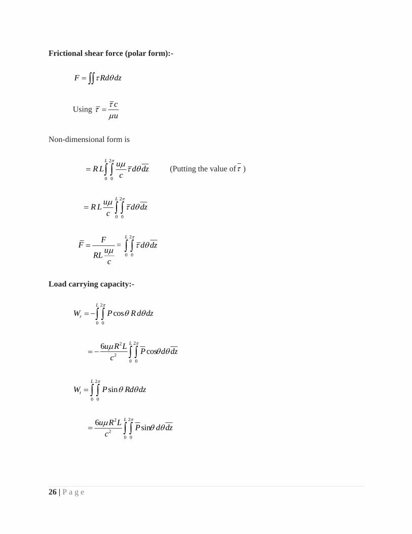
Frictional shear force (polar form):-
F Rd dz
Using c
u
Non-dimensional form is
2
0 0
Lu
R L d dzc
(Putting the value of )
2
0 0
Lu
R L d dzc
F
Fu
RLc
=
2
0 0
L
d dz
Load carrying capacity:-
2
0 0
cosL
rW P R d dz
22
2
0 0
6cos
Lu R L
P d dzc
2
0 0
sinL
tW P Rd dz
22
2
0 0
6sin
Lu R L
P d dzc

27 | P a g e
Net load 2 2
rW W W
22
2
0 0
6L
u R LPd dz
c
2
2
6
WW
u R L
c
=
2
0 0
L
Pd dz
Friction parameter -:
The force known as friction can be defined as resistance suffered by the body in relative motion
by moving against each other. Coefficient of friction is defined as the ratio between the frictional
force and normal load and is generally denoted by or . Coefficient of friction is the
characteristics of tribological system but it is not a material characteristics. The term coefficient
of friction is usually used in science and engineering
We can find friction parameter by -:
/F W
Where
=coefficient of friction
F=frictional force
W=load carrying capacity of journal
Flow rate (Q)-:
The high heat intensity developed inside the bearings of modern machines, particularly the crank
pin bearing part of engine definitely requires the correct control of heat flows. Generally the heat

28 | P a g e
removal is directly proportional to the amount of lubricant flowing inside it, lubricant flow rate is
one of major factors which controls the temperature inside the bearing and consequently its
reliability and life.
We can find flow rate by -:
2
0 0
( ^ 3)* / 4
Lp
q hz
Damping and stiffness coefficient-:
In modern era the need of increasing speed yet reliable operation of rotating machinery is
increasing day by day and to achieve this we have to predict the dynamic response and stability
of a rotor bearing system in an accurate way. Generally rotating machinery is supported by a one
or more journal which plays a vital role in system, since it permits the relative motion between
stationary and moving parts.
There are generally two types of bearings -:
1-: Fluid-film bearing
2-: Rolling-element bearing
Most of the machine of our era uses fluid-film bearing; it has large number of applications which
varies from small electric motors to automobile and aircraft piston engines to large steam engines
for electric power generation. In fluid-film bearing fluid-film is a thin film that separates the
bearing to keep in contact with the journal, it acts like a spring and provides damping. Stiffness
and damping properties of the fluid-film bearing alter the critical speed and out of balance
response of rotor.

29 | P a g e
Non dimensional damping and stiffness coefficient can be calculated by:
2
0 0
(cos )
L
xk p d dz
(3.18)
2
0 0
(cos )
L
z yk p d dz
(3.19)
2
0 0
(sin )
L
z xk p d dz
(3.20)
2
0 0
(sin )
L
z z yk p d dz
(3.21)
2
0 0
(cos )
L
xb p d dz
(3.22)
2
0 0
(cos )
L
z yb p d dz
(3.23)
2
0 0
(sin )
L
z xb p d dz
(3.24)
2
0 0
(sin )
L
z z yb p d dz
(3.25)
Where
k , zk , zk . z zk are the non-dimensional stiffness in different directions and b , zb , zb , z zb
are the non-dimensional damping coefficients in different directions which are calculated by
infinitely perturbation method [50].
The governing equation for the pressure distribution in hydro dynamic journal bearing film is-:
30 | P a g e
3 3
2
1 1
12 12 2
h p h p h h
R z z t
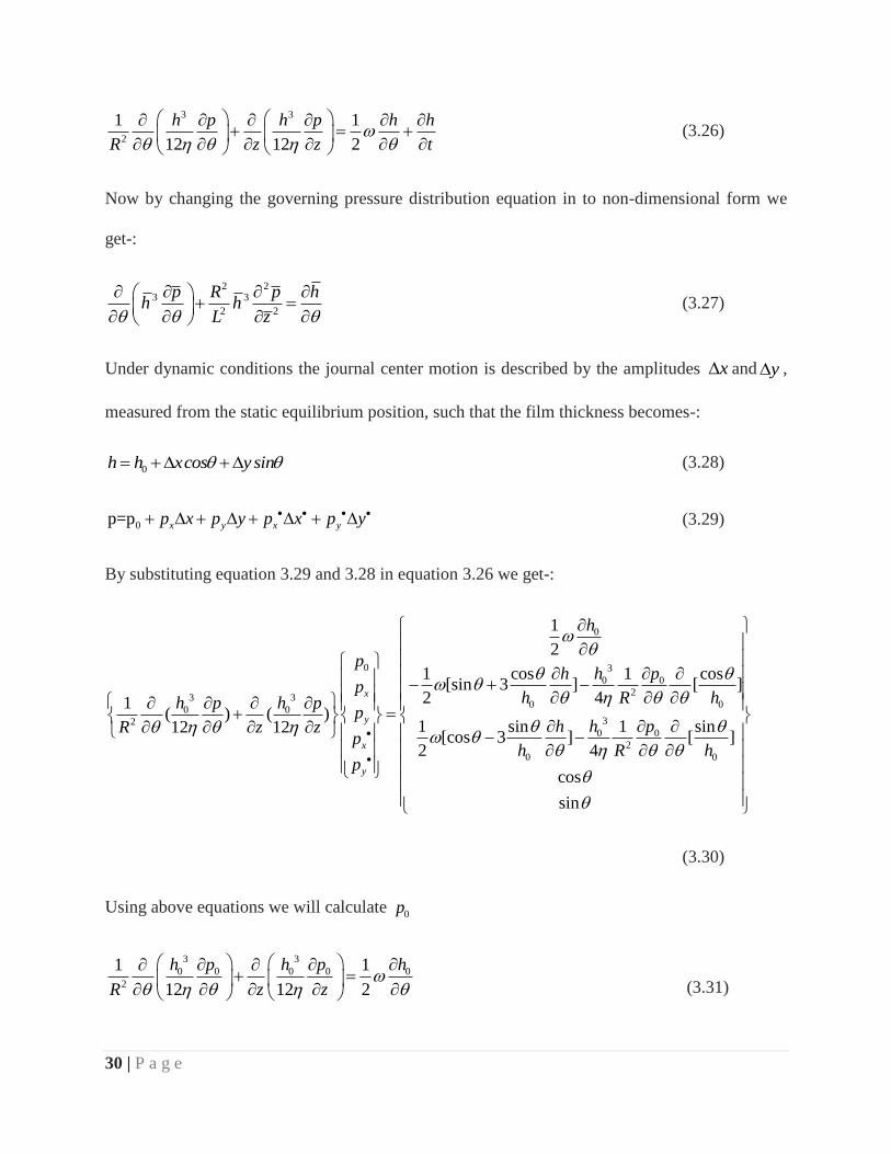
(3.26)
Now by changing the governing pressure distribution equation in to non-dimensional form we
get-:
2 23 3
2 2
p R p hh h
L z
(3.27)
Under dynamic conditions the journal center motion is described by the amplitudes x and y ,
measured from the static equilibrium position, such that the film thickness becomes-:
0h h xcos y sin (3.28)
0p=p x y x yp x p y p x p y (3.29)
By substituting equation 3.29 and 3.28 in equation 3.26 we get-:
0
0 3
0 0
23 3
0 00 0
320 0
2
0 0
1
2
1 cos 1 cos[sin 3 ] [ ]
2 41( ) ( )
1 sin 1 sin12 12[cos 3 ] [ ]
2 4
cos
sin
x
y
x
y
h
ph h p
ph R hh p h p
ph h pR z z
ph R h
p
(3.30)
Using above equations we will calculate 0p
3 3
0 0 0 0 0
2
1 1
12 12 2
h p h p h
R z z
(3.31)

31 | P a g e
First of all we will non dimensionlized the above equation so that all the values which we are
calculating can be used universally for all the bearings.
By multiplying equation 3.31 by 212 R we get-
23 2 3 20 0 0
0 0 2
1*12
2
p p hh R h R
z
(3.32)
Making the above equation dimensionless by using the following,
hh
c ,
2
00 26
p cp
R ,
zz
L
22 2 23 3 3 3 20 0 0
0 02 2 2 2
6 6 1* 12
2
p p hR R Rh c h c R c
c L z c
(3.33)
Eliminate 26 R c from whole equation
223 30 0 0
0 02 2
p p hRh h
L z
(3.34)
2 223 2 30 0 0 0 0
0 0 02 2 23
p p h p hRh h h
L z
(3.35)
The above equation 3.35 is the non dimensionlized form of equation 3.31.
Now on dividing whole equation 3.35 by 3
0h we get-:
2 22
0 0 0 0 0
2 2 2 3
0 0
3 1p p h p hR
h L z h
(3.36)
On applying finite difference method in equation 3.36 we get pressure in the form of-:

32 | P a g e
0
A B C Dp
E
Where A= 1, 1,0 0i j i j
P P
B= , 1 , 1
2 2
0 02 2[ ]
i j i j
RP P
L z
C= 1, 1,0 0
0
3sin [ ]
2 i j i jP P
h
D= 2
3
0
sinh
E= 2 2
2 22 1
R
L z
Similarly we can calculatexp , yp , xp
, yp and by putting these all in equation 3.18 to 3.25 we
will calculate stiffness and damping coefficients.
1 1 1 1
1
x
A B C Dp
E
A1= 1, 1,i j i jx xP P
B1= , 1 , 1
2 2
2 2[ ]
i j i jx x
RP P
L z
C1= 1, 1,
0
3sin [ ]
2 i j i jx xP Ph
D1= 1, 1,
20 0
0 03
0 0
3 cos sinsin 3 ( sin cos sin )
2
i j i jp p
h hh h

33 | P a g e
E1= 2 2
2 22 1 ( )
R
L z
2 2 2 2
2
y
A B C Dp
E
A2= 1, 1,i j i jy yP P
B2= , 1 , 1
2 2
2 2[ ]
i j i jy y
RP P
L z
C2= 1, 1,
0
3sin [ ]
2 i j i jy yP Ph
D2= 1, 1,
2 20 02
0 03
0 0
3 sincos 3 ( cos sin )
2
i j i jp p
h hh h
E2= 2 2
2 22 1
R
L z
Similarly for xp
3 3 3 3
3
x
A B C Dp
E
A3= 1, 1,i j i jx xp p
B3= , 1 , 1
2 2
2 2[ ]
i j i jx x
Rp p
L z
C3= 1, 1,
0
3sin [ ]
2 i j i jx xp ph

34 | P a g e
D3= 2
3
0
cos2 *
h
E3= 2 2
2 22 1
R
L z
Similarly for yp
4 4 4 4
4
y
A B C Dp
E
A4= 1, 1,i j i jy yp p
B4= , 1 , 1
2 2
2 2[ ]
i j i jy y
Rp p
L z
C4= 1, 1,
0
3sin [ ]
2 i j i jy yp ph
D4= 2
3
0
sin2* *
h
E4= 2 2
2 22 1
R
L z
By putting values ofxp , yp , xp
, yp in equations 3.18 to 3.25, we will get various values of
stiffness and damping coefficient.

35 | P a g e
Flow Chart to calculate pressure profile and other parameters of spherical textured journal bearing
Fig. 3.2 Flow chart (static characteristics)
Yes
Start
Input control variables, asperity ratio,
eccentricity ratio, texture height ratio etc.
Generate the mesh grid and calculate the film
thickness at each grid point
Stop
Yes
Solve Reynolds equation to find pressure with the
help of central Finite Difference method
No Check
Convergence
Calculate non dimensional pressure, load
carrying capacity, Flow rate
36 | P a g e
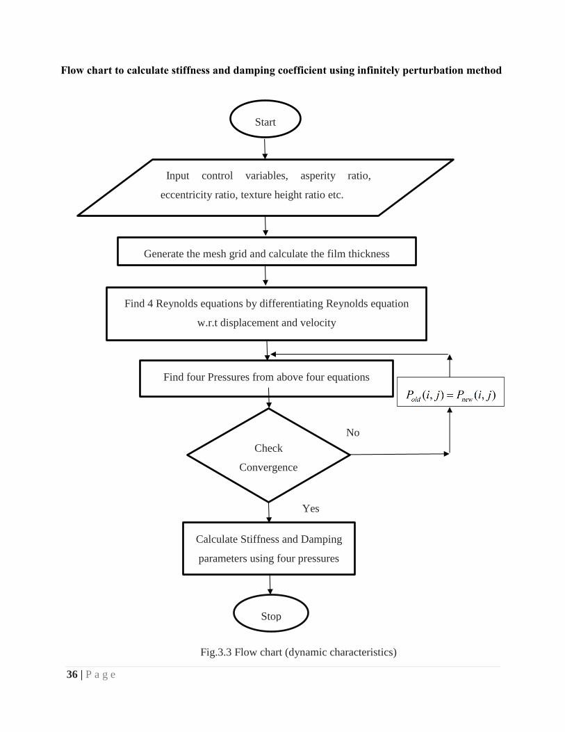
Flow chart to calculate stiffness and damping coefficient using infinitely perturbation method
Fig.3.3 Flow chart (dynamic characteristics)
Start
Input control variables, asperity ratio,
eccentricity ratio, texture height ratio etc.
Generate the mesh grid and calculate the film thickness
Find 4 Reynolds equations by differentiating Reynolds equation
w.r.t displacement and velocity
Find four Pressures from above four equations
Check
Convergence
Calculate Stiffness and Damping
parameters using four pressures
Stop
Yes
No

37 | P a g e
Chapter 4
Result and Discussion
Theoretical and graphical analysis of texture is done on the hydrodynamic journal bearing to
study its effect on parameters of journal bearing. In present analysis we are studying the effect of
eccentricity ratio, asperity ratio and texture height on non-dimensional load, friction parameter,
non-dimensional flow rate, stiffness coefficients and damping coefficients.
4.1 What is aspect ratio and texture height ratio?
For numerical analysis, the bearing surface is modeled by dividing into finite number of squares
(unit cell) which are equal to number of asperities, i.e. each unit cell contain one asperity. Aspect
Ratio is defined as ratio of projected area of asperities to total area of square. Similarly each
asperity has some height, when the maximum height of the asperity is divided by the width of the
unit cell it gives the texture height ratio. Figure 4.1 shows asperities with different aspect ratio
and height ratio for better understanding of the terms.
Fig.4.1 Modelling with different aspect ratio and texture height ratio
0
0.2
0.4
0.6
0.8
1
0
0.2
0.4
0.6
0.8
1
0
0.1
0.2
Width
Spherical Asperity: Aspect Ratio=0.2, Texture Height Ratio =0.2
Breadth
Heig
ht
0
0.2
0.4
0.6
0.8
1
0
0.2
0.4
0.6
0.8
1
0
0.1
0.2
Width
Spherical Asperity: Aspect Ratio=0.8, Texture Height Ratio =0.2
Breadth
Heig
ht

38 | P a g e
Fig.4.2 Modelling with different aspect ratio and texture height ratio
How spherical textured hydrodynamic bearing does looks alike?
Fig.4.3 Textured bearing
Texture bearing have undulations or micro asperities or dimples or texture which are created
inside the surface by bearing by some surface texturing techniques, the bearing will look like as
shown in fig.4.3 . Fig.4.4 shows the zoomed view of spherical micro asperities on the surface of
bearing.
0
0.20.4
0.6
0.81
0
0.2
0.4
0.6
0.8
1
0
0.2
0.4
0.6
0.8
Width
Spherical Asperity: Aspect Ratio=0.5, Texture Height Ratio =0.5
Breadth
Heig
ht
00.2
0.40.6
0.81
0
0.2
0.4
0.6
0.8
1
0
0.2
0.4
0.6
0.8
Width
Spherical Asperity: Aspect Ratio=0.2, Texture Height Ratio =0.8
Breadth
Heig
ht
Fig 4.4 Zoomed micro asperities on journal
bearing surface
39 | P a g e
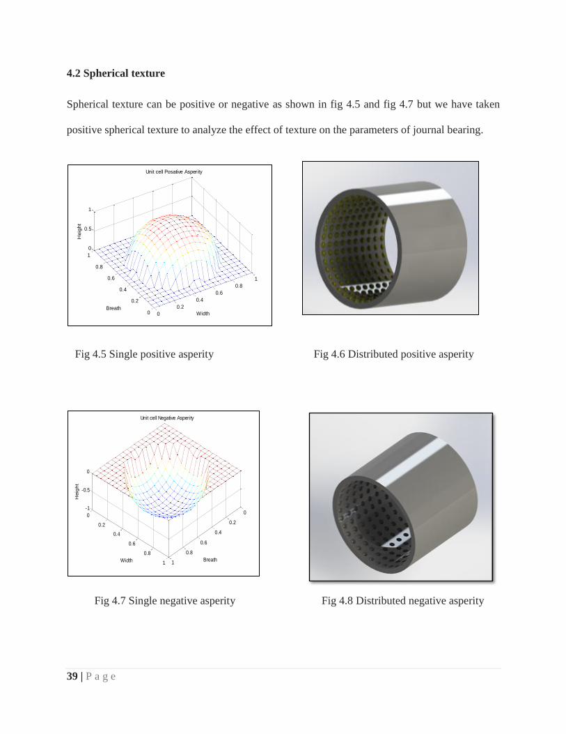
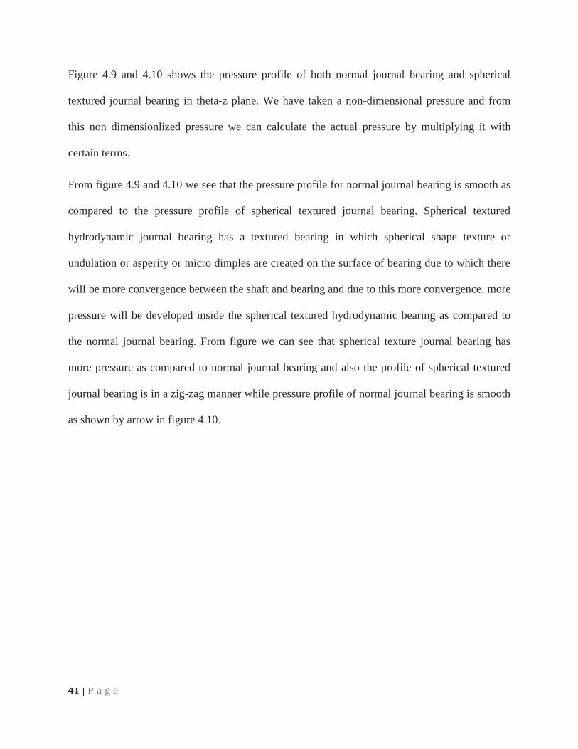
4.2 Spherical texture
Spherical texture can be positive or negative as shown in fig 4.5 and fig 4.7 but we have taken
positive spherical texture to analyze the effect of texture on the parameters of journal bearing.
Fig 4.5 Single positive asperity Fig 4.6 Distributed positive asperity
Fig 4.7 Single negative asperity Fig 4.8 Distributed negative asperity
0
0.2
0.4
0.6
0.8
1
0
0.2
0.4
0.6
0.8
1
-1
-0.5
0
Breath
Unit cell Negative Asperity
Width
Heig
ht
0
0.2
0.4
0.6
0.8
1
0
0.2
0.4
0.6
0.8
1
0
0.5
1
Width
Unit cell Posative Asperity
Breath
Heig
ht

40 | P a g e
Above are micron scaled surface featured with spherical asperity on a surface. Model of single
positive asperity and distributed positive asperity is shown in figure 4.5 and figure 4.6 whereas
model of single negative asperity and distributed negative asperity is shown in figure 4.7 and
figure 4.8.
Asperities can be of many types such as square, rectangular, elliptical, cylindrical, spherical etc.
also they can be positive or negative but from all these types of asperities we are taking only
spherical asperity and its effects on the parameters of hydrodynamic journal bearing because
from all these types of asperities only spherical asperity will give optimum result.
4.3 Comparison between pressure profile of normal and negative spherical textured
journal bearing on varying eccentricity ratio
Fig. 4.9 Pressure profile of
normal journal bearing
Fig. 4.10 Pressure profile of spherical
textured journal bearing
41 | P a g e
Figure 4.9 and 4.10 shows the pressure profile of both normal journal bearing and spherical
textured journal bearing in theta-z plane. We have taken a non-dimensional pressure and from
this non dimensionlized pressure we can calculate the actual pressure by multiplying it with
certain terms.
From figure 4.9 and 4.10 we see that the pressure profile for normal journal bearing is smooth as
compared to the pressure profile of spherical textured journal bearing. Spherical textured
hydrodynamic journal bearing has a textured bearing in which spherical shape texture or
undulation or asperity or micro dimples are created on the surface of bearing due to which there
will be more convergence between the shaft and bearing and due to this more convergence, more
pressure will be developed inside the spherical textured hydrodynamic bearing as compared to
the normal journal bearing. From figure we can see that spherical texture journal bearing has
more pressure as compared to normal journal bearing and also the profile of spherical textured
journal bearing is in a zig-zag manner while pressure profile of normal journal bearing is smooth
as shown by arrow in figure 4.10.

42 | P a g e
4.4 Effect on non-dimensional load carrying capacity of both spherical textured and
normal journal bearing on varying eccentricity ratio
The above graph is in between eccentricity ratio vs non dimensional load for negative spherical
asperity. We have taken eccentricity ratio as abscissa because radial clearance is in our control,
we can increase or decrease eccentricity ratio by varying radial clearance. Eccentricity ratio is
the ratio of eccentricity to the radial clearance. From fig 4.11 we get that on increasing
eccentricity ratio load carrying capacity of both normal and textured bearing increases, but in
latter case it increases more than normal journal bearing because in textured journal bearing
more pressure will be there due to the more convergence which happen due to the texture
formation on the surface of bearing and due to this more pressure it can carry large amount of
0.1 0.2 0.3 0.4 0.5 0.6 0.7 0.80
0.2
0.4
0.6
0.8
1
1.2
1.4
1.6
1.8x 10
-4
Eccentricity Ratio
Non-d
imensio
n L
oad
Spherical asperity: Asperity ratio=0.5, Texture height ratio=0.5
Textured Surface
Smooth Surface
Fig 4.11 Eccentricity ratio vs Non dimensional load

43 | P a g e
load, so by varying eccentricity ratio from 0.1 to 0.8 we see that after reaching eccentricity ratio
0.6 there is an sudden increment in load carrying capacity of texture journal bearing.
4.5 Effect on non-dimensional friction parameter of both normal and spherical textured
journal bearing on varying eccentricity ratio
In industries friction is the term which is generally used now and then, friction is directly
proportional to power, more the friction, more will be the wastage of power. In order to
minimize the wastage of power we have to control friction. In above figure blue color is for
textured journal bearing and red color is for normal journal bearing. As we can see from the
0.1 0.2 0.3 0.4 0.5 0.6 0.7 0.80
1
2
3
4
5
6
7x 10
4
Eccentricity Ratio
Nom
dim
ensio
nal fr
iction p
ara
mete
r
Spherical asperity: Asperity ratio=0.5, texture height ratio=0.5
Textured Surface
Smooth Surface
Fig. 4.12 Eccentricity ratio vs friction parameter

44 | P a g e
figure that during starting, non-dimensional coefficient of friction parameter is more in textured
journal bearing than normal journal bearing, but as soon as we reach the eccentricity ratio i.e. 0.6
it becomes almost equal or less after that as shown in figure 4.12.
4.6 Effect of surface texture on lubricant flow rate on both spherical textured and normal
journal bearing on varying eccentricity ratio
Fig 4.13 Eccentricity ratio vs Non dimensional flow rate
To control friction in journal bearing, lubrication is provided inside the journal bearing so that
we can control power loss by reducing friction. Figure 4.13 shows a comparison of flow rate of
lubricant inside the normal journal bearing and inside the spherically textured journal bearing.
From figure we can see that lubricant flow rate in textured journal bearing is less than that of
normal journal bearing, it is because, in spherically textured journal bearing, texture behaves as a
0.1 0.2 0.3 0.4 0.5 0.6 0.7 0.80
0.005
0.01
0.015
0.02
0.025
0.03
0.035
0.04
0.045
0.05
Eccentricity Ratio
Non
dim
ensi
onal
flo
w r
ate
Spherical asperity: Aspect ratio=0.5, Texture height ratio=0.5
Textured Surface
Smooth Surface

45 | P a g e
reservoir which stores lubricant and provide it during starving condition, so there is less wastage
of lubricant in textured journal bearing as compared to normal bearing.
4.7 Variation of various stiffness coefficients on varying eccentricity ratio for normal
journal bearing
Fig 4.14 Eccentricity ratio vs Non dimensional stiffness coefficient (normal bearing)
Above figure shows the variation of various non dimensional stiffness coefficients on varying
eccentricity ratio for normal journal bearing. k and z zk lines on graph have constant slope,
whereas the slope of zk , zk line on graph is positive and increasing .Thus we can conclude
from the above figure that on increasing eccentricity ratio stiffness coefficient zk and zk
increases while the other two stiffness coefficients remain constant.
0.1 0.2 0.3 0.4 0.5 0.6 0.7 0.8-2
0
2
4
6
8
10
12
Eccentricity Ratio
Non
Dim
ensi
onal
Stif
fnes
s co
effic
ient
s
Stifness of Journal bearing without Texture
k
kz
kz
kzz

46 | P a g e
4.8 Variation of various stiffness coefficients on varying eccentricity ratio for negative
spherical textured journal bearing
Fluid film stiffness coefficients are affected by the behavior of lubricant, from figure 4.14 we can
see that on increasing eccentricity ratio, stiffness coefficient of the spherically textured journal
bearing zk and zk increases whereas both the other stiffness coefficients have no effect or very
small effect. On comparing figure 4.14 and 4.15 we get that stiffness coefficient of spherically
textured journal bearing is slightly less than that of normal journal bearing. The role of stiffness
is to provide the journal a restoring force that pushes back journal towards its steady state
equilibrium condition.
0.1 0.2 0.3 0.4 0.5 0.6 0.7 0.8-1
0
1
2
3
4
5
6
7
8
Eccentricity Ratio
Non d
imensio
nal S
tiff
ness c
oeff
icie
nts
Spherical asperity: Aspect ratio=0.7, Texture height ratio=0.7
k
kz
kz
kzz
Fig 4.15 Eccentricity ratio vs Non dimensional stiffness coefficients
(textured bearing)

47 | P a g e
4.9 Variation of various damping coefficient on varying eccentricity ratio for normal
journal bearing
Fig 4.16 Eccentricity ratio vs Non dimensional damping coefficient (normal bearing)
Above figure shows the variation of damping coefficients of normal journal bearing on varying
eccentricity ratio. From above figure we can see that damping coefficient zb and zb are almost
equal while damping coefficient b and z zb increases on increasing eccentricity ratio, later one
initially has larger value than the former one as shown in figure. Slope of both b and z zb are
positive and increasing.
Damping is generally provided for following purpose:
In order to pass through critical speeds.
To suppress instabilities and sub synchronous vibration.
0.1 0.2 0.3 0.4 0.5 0.6 0.7 0.8-2
0
2
4
6
8
10
12
14
16
Eccentricity Ratio
Non
dim
ensi
onal
dam
ping
coe
ffic
ient
s
Damping of Journal bearing without Texture
b
bz
bz
bzz

48 | P a g e
To reduce noise.
Able to withstand shock loads
Reduced transmitted vibration.
4.10 Variation of various damping coefficient of negative spherical textured journal
bearing on varying eccentricity ratio
Fig. 4.17 Eccentricity ratio vs Non dimensional damping coefficients (textured bearing)
From above figure we can see that for a spherically textured hydrodynamic journal bearing, on
increasing the eccentricity ratio of spherically textured journal bearing, damping coefficient zb
and zb remains unchanged whereas damping coefficients b and z zb increases with it, the later
one has initially higher value than the former one. On comparing figure 4.16 and 4.17 we get that
damping coefficients of textured bearing is slightly less than the normal bearing.
0.1 0.2 0.3 0.4 0.5 0.6 0.7 0.8-2
0
2
4
6
8
10
12
14
Eccentricity Ratio
Non
dim
ensi
onal
dam
ping
coe
ffic
ient
s
Spherical asperity: Aspect ratio=0.5, Texture height ratio=0.5
b
bz
bz
bzz

49 | P a g e
4.11 Variation of load for different number of textures on varying asperity ratio for
spherically textured journal bearing
From above figure we can see that for spherically textured hydrodynamic journal bearing, on
varying asperity ratio (ratio of area of dimple to the area of cell) for different number of textures
how non dimensional load is varying. Each line of different colors indicates the number of
textures used to calculate non dimension load by varying asperity ratio for e.g. black line is for
5X50 number of textures, and on varying asperity ratio, non-dimension load also increase
therefore the slope of black line is positive, from figure we observe that the surface having less
number of textures have slightly high load carrying capacity than others because as soon as we
0.1 0.2 0.3 0.4 0.5 0.6 0.7 0.81
2
3
4
5
6
7
8x 10
-4
Asperity ratio
Non-d
imensio
n L
oad
Asperity ratio Vs Non-dimension Load
1X50
2X50
3X50
4X50
5X50
Fig 4.18 Asperity ratio vs Non dimensional load

50 | P a g e
cross the limit of increasing the number of textures , the surface instead of becoming rough will
become smooth.
4.12 Variation of coefficient of friction parameter for different number of textures on
varying asperity ratio for spherically textured journal bearing
As we can see that from the above figure that for a spherically textured hydrodynamic journal
bearing, on increasing the aspect ratio (area of dimple to the area of cell), coefficient of friction
parameters decreases, and with increase in number of textures on the surface, coefficient of
friction parameter increases for e.g. coefficient of friction parameter of surface having textures
5X50 is more than the surface having textures 1X50, so from above we can conclude that, more
the number of textures on the surface, more will be the coefficient of friction parameter. Slope of
0.1 0.2 0.3 0.4 0.5 0.6 0.7 0.81
1.5
2
2.5
3
3.5
4x 10
7
Aspect Ratio
Coe
ffic
ient
of
Fric
tion
para
met
er
Aspect Ratio Vs Coefficient of friction
1X50
2X50
3X50
4X50
5X50
Fig 4.19 Aspect ratio Vs Coefficient of friction parameter
51 | P a g e
the curve between asperity ratio and coefficient of friction parameter is negative because
coefficient of friction is decreasing as we increase the asperity ratio.
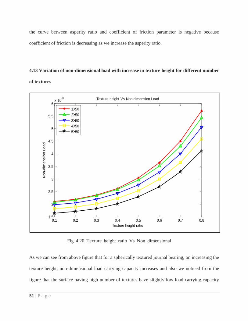
4.13 Variation of non-dimensional load with increase in texture height for different number
of textures
As we can see from above figure that for a spherically textured journal bearing, on increasing the
texture height, non-dimensional load carrying capacity increases and also we noticed from the
figure that the surface having high number of textures have slightly low load carrying capacity
0.1 0.2 0.3 0.4 0.5 0.6 0.7 0.81.5
2
2.5
3
3.5
4
4.5
5
5.5
6x 10
-3
Texture height ratio
Non-d
imensio
n L
oad
Texture height Vs Non-dimension Load
1X50
2X50
3X50
4X50
5X50
Fig 4.20 Texture height ratio Vs Non dimensional
load
52 | P a g e
than remaining others for e.g. surface having texture 3X50(blue line) have larger load carrying
capacity than surface having texture 5X50(black line). Slope of the curve is positive because as
we are increase the texture height, non-dimensional load carrying capacity also increases.
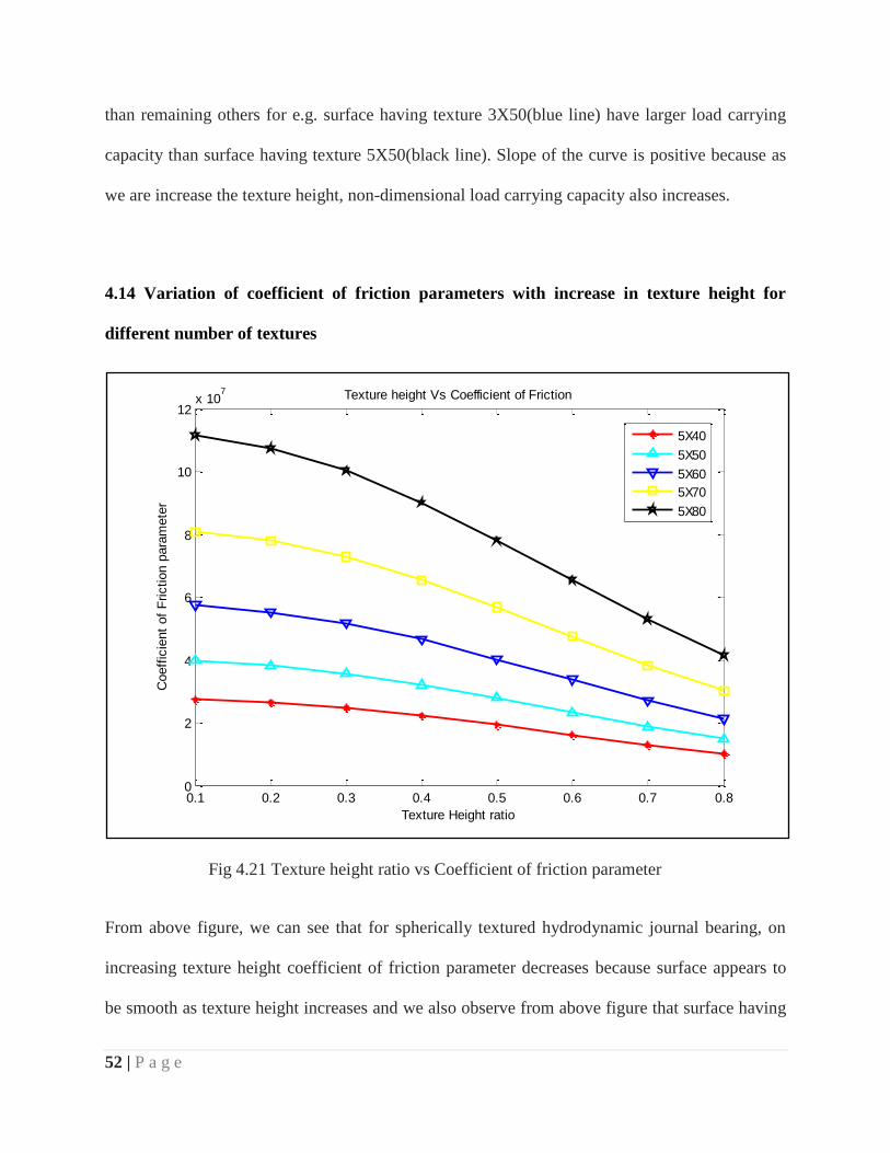
4.14 Variation of coefficient of friction parameters with increase in texture height for
different number of textures
From above figure, we can see that for spherically textured hydrodynamic journal bearing, on
increasing texture height coefficient of friction parameter decreases because surface appears to
be smooth as texture height increases and we also observe from above figure that surface having
0.1 0.2 0.3 0.4 0.5 0.6 0.7 0.80
2
4
6
8
10
12x 10
7
Texture Height ratio
Coeff
icie
nt
of
Friction p
ara
mete
r
Texture height Vs Coefficient of Friction
5X40
5X50
5X60
5X70
5X80
Fig 4.21 Texture height ratio vs Coefficient of friction parameter

53 | P a g e
higher number of textures on it, having more coefficient of friction parameters than the surface
having low number of textures. This is because, surface having higher number of textures, have
higher roughness due to the texture portion, which will increase friction for e.g. surface having
5X80(black curve) number of textures have high coefficient of friction parameter than the
surface having 5X40(red curve) as shown in figure 4.21.Slope of all curves is negative because
as we are increase texture height coefficient of friction parameter decreases.
54 | P a g e
Chapter 5
Conclusion and Future Scope
5.1 Conclusion
On increasing eccentricity ratio, the non-dimensional load carrying capacity of
hydrodynamic journal bearing increases for both spherically textured as well as for
normal bearing, but non-dimensional load carrying capacity is more for the former one.
With increase in eccentricity ratio, the coefficient of friction parameter of hydrodynamic
journal bearing decreases for both spherically textured and normal bearing.
On increasing eccentricity ratio, the non-dimensional flow rate increases for both
spherically textured hydrodynamic journal bearing and normal journal bearing but it
increases more for the latter one.
With increase in eccentricity ratio, stiffness of spherically textured journal bearing is
slightly less than that of normal journal bearing.
On increasing eccentricity ratio, damping of spherically textured journal bearing is
slightly less than that of normal journal bearing.
On increasing in asperity ratio, non-dimensional load carrying capacity increases for
spherically textured hydrodynamic journal bearing.
With increase in number of textures, non-dimensional load carrying capacity decreases.
On increasing asperity ratio, coefficient of friction parameter for spherically textured
hydrodynamic journal bearing decreases.
With increase in number of textures, coefficient of friction parameter increases for
spherically textured hydrodynamic journal bearing.

55 | P a g e
On increasing texture height, non-dimensional load carrying capacity increases for
spherically textured hydrodynamic journal bearing.
With increase in texture height, coefficient of friction parameter decreases for spherically
textured hydrodynamic journal bearing.
5.2 Future scope
Study the behavior of dynamic characteristics of spherically textured journal bearings by
distributed texture partially on the bearing surface.
To provide spherical texture on piston cylinder arrangement between piston and piston
rings and analyze its effect on the dynamic characteristics of the system.
Study the behavior of dynamic characteristics of journal bearing, by applying different
shapes of texture.
Experimental validification of results.
56 | P a g e
References
1. Tower, B.1883, First and second report on friction experiments (friction of lubricated
bearings), Proc. Inst. Mech. Engrs.London.UK.p.659 andpp.58-70.
2. Petroff, N. (1883), Friction in machines and the effect of lubrication(in Russian), Inzh.
Zh. St. Petersburg, 1-4(71), 227,377,535.
3. Reynolds, O. (1886), On the theory of lubrication and its application to Mr. Beauchamp
Tower’s experiments, including an experimental determination of the viscosity of olive
oil, Phil. Trans. Royal Society, 177,157-234.
4. Sommerfeld, A. (1904), Zur Hydrodynamischen Theorie der Schmiermittelreibung, Z.
Angrew. Math. Phys., 50, 97-155.
5. Kingsbury. A. (1913), Experiments with an air lubricated bearing, Journal of American
Society of Naval Engineers, 9.
6. Leonardo da Vinci (1938), The Notebooks of Leonardo da Vinci, E. Macardy (ed.),
Reynal & Hitchcock, Newyork.
7. Coulomb, C.A. (1785), Theorie des Machines Simples, Mem. Math, phys. Acad. Sci, 10,
161.
8. Amonton, G. (1699), De la Resistance Causee dams les Machine, Royal Society (Paris),
206.
9. Hardy, W.B. (1950), Collected Scientific Papers, Cambridge University Press, 1936.
10. Bowen, F.P. and Tabor, D. (1950), The Friction and Lubrication of Solids, Oxford Press,
Cambridge.
11. Weichsel, Dick (1994-10-03), "Plane bearings" ESC Report 5 (1).
12. McMaster-Carr catalog, (115th ed.), McMaster-Carr, p. 1119, retrieved 2009-12-20.

57 | P a g e
13. Oilite, archived from the original on 2009-12-16, retrieved 2009-12-16.
14. Curcio, Vincent (2001), Chrysler: The Life and Times of an Automotive Genius, Oxford
University Press US, p. 485, ISBN 978-0-19-514705-6.
15. McMaster-Carr catalog, McMaster-Carr, p. 1118, retrieved 2009-12-20.
16. Iglide, pp. 1.2–1.3, archived from the original on 2009-12-10, retrieved2009-12-10.
17. Journal Bearings, archived from the original on 2010-05-08, retrieved2010-05-08.
18. Bently.D. & Hatch.C. "Fundamentals of Rotating Machinery Diagnostics", pps480 -
489. (2002).
19. Neale 1995, "Fundamentals of Rotating Machinery Diagnostics", p. A10.4.
20. Bearings and bearing metals 1921, p. 1.
21. Car and Locomotive Cyclopedia Of American Practice.
22. Brumbach, Michael E.; Clade, Jeffrey A. (2003), Industrial Maintenance, Cengage
Learning, p. 199, ISBN 978-0-7668-2695-3.
23. Neale 1995, p. A12.1.
24. Journal Bearings, archived from the original on 2010-05-08, retrieved2010-05-08.
25. Mobley, R. Keith (2001), Plant engineer's handbook (5th ed.), Butterworth-Heinemann,
p. 1094, ISBN 978-0-7506-7328-0.
26. Neale 1995, p. A11.6.
27. O. O. Ajayi, A. C. Greco, R. A. Erck, and G. R. Fenske Argonne, National Laboratory
June 10, 2010.
28. Priest M., Taylor C.M., 2000, Automobile engine tribology - approaching the surface,
Wear, 241, pp. 193-203.

58 | P a g e
29. U. Pettersson, S. Jacobson, Influence of surface texture on boundary lubricated sliding
contacts, Tribol. Int. 36 (2003) 857–864
30. Wakuda, M., Yamauchi, Y., Kanzaki, S., Yasuda, Y., 2003, Effect of Surface Texturing
on Friction Reduction Between Ceramic and Steel Materials under Lubricated Sliding
Contact, Wear, 254. pp. 356-363.
31. Siripuram, R.B., Stephens, L.S., 2004, Effect of Deterministic Asperity Geometry on
Hydrodynamic Lubrication", Journal of Tribology, 126, pp., 527-534.
32. Kovalchenko, A., Ajayi, O., Erdemir, A., Fenske, G., Etsion, I., 2005, The effect of laser
surface texturing on transitions in lubrication regimes during unidirectional sliding
contact Tribology International, 38. pp. 219-225.
33. Mehenny D.S. Taylor, Taylor C.M., 2000, Influence of circumferential waviness on
engine bearing performance, Journal of Mechanical Engineering Science, 214, pp. 51-61.
34. Ronen, A., Etsion, I., Kligerman, Y., 2001, Friction-Reducing Surface-Texturing in
Reciprocating Automotive Components, Tribology Transactions, 44, 3, pp. 359-366.
35. Brizmer, V., Kligerman, Y., Etsion, I., 2003, A Laser Textured Parallel Thrust Bearing,
Tribology Transactions, 46, 3, pp. 397-403.
36. Christensen, H., "Stochastic Models for Hydrodynamic Lubrication of rough surfaces” in
Proc IMechE, 184, Pan 1, 55, pp 1019-1026. (1969-1970)
37. Tonder, I1, "Mathematical Verification of the Applicability of Modified Reynolds
Equation to Striated Rough Surfaces," Wear, 44, 2, pp 329-343, (1977).
38. Elrod, H. G., "Thin-Film Lubrication Theory for Newtonian Fluids Possessing Striated
Roughness or Grooving," ASME Jour. of Trib., 93, 3, pp324-330. (1973).

59 | P a g e
39. Patir. N. and Cheng, H. s., "An Averaged Flow Model for Determining Effects of Three-
Dimensional Roughness on Partial Hydrodynamic Lubrication."Tram. ASME, Series F,
100, pp 12-17, (1978).
40. Rhow, S. K and Elrod, H. G., "The Effects on Bearing Load-Carrying Capacity of Two-
Sided Striated Roughness," ASME Jour. of Lubr. Tech.. 94,1, pp 554560, (1974).
41. Prakash, J., "On the Lubrication of Rough Rollers," ASME Jour. of Trib., 106, 3. pp 324-
330. (1984).
42. Zhang, C. and Qiu, Z., "Effects of Surface Roughness and Lubricant Non-Newtonian
Property on the performance of IC Engine Journal Bearings,"Chinese Intmal Cornburlion
Engine Eng., 16, 1, pp 69-76, (1995).
43. Zhang, C. and Qiu, Z., "Analysis of TwoSided Roughness and Non-Newtonian Effects
in Dynamically Loaded Finite Journal Bearings," in Roc. of the In11 Tnb. Conf:,
Yokohama. pp 1005-1010, (1995).
44. Patir. N. and Cheng, H. s., "An Averaged Flow Model for Determining Effects of Three-
Dimensional Roughness on Partial Hydrodynamic Lubrication."Tram. ASME, Series F,
100, pp 12-17, (1978).
45. Boedo, S. and Booker, J. F., "Body Force and Roughness Effects in A Mass-Conserving
Model-Based Elastohydrodynamic Lubrication Model," in Roc. of the Inl'l Tnb. hf:,
Yokohama, pp 1061-1066. (1995).
46. Brizmer, V., Kligerman, Y., and Etsion, I., 2003, “A Laser Surface Textured Parallel
Thrust Bearing,” Tribol. Trans., 46_3_, pp. 397–403.
47. Ronen, A., Etsion, I., Kligerman, Y., 2001, Friction-Reducing Surface-Texturing in
Reciprocating Automotive Components, Tribology Transactions, 44, 3, pp. 359-366.

60 | P a g e
48. Yu, T. H., and Sadeghi, F., 2001, “Groove Effects on Thrust Washer
Lubrication,”ASME J. Tribol., 123_2_, pp. 295–304.
49. Sahlin, F., Glavatskih, S. B., Almqvist, T., and Larsson, R., 2005, “Two-Dimensional
CFD-Analysis of Micro-Patterned Surfaces in Hydrodynamic Lubrication,”Trans.
ASME, J. Tribol., 127_1_, pp. 96–102.
50. T S Reddy Ganji and S K Kakoty, “DYNAMIC CHARACTERISTICS AND
STABILITY OFCYLINDRICAL TEXTURED JOURNAL BEARING” Department of
Mechanical Engineering, Indian Institute of Technology Guwahati, Assam, India