Analysis of Punch and Die for Forming Sheet metal ... · Analysis of Punch and Die for Forming...
5
International Journal of Trend in Research and Development, Volume 3(5), ISSN: 2394-9333 www.ijtrd.com IJTRD | Sep-Oct 2016 Available [email protected] 342 Analysis of Punch and Die for Forming Sheet metal component using Finite Element Method 1 Raghavendra, 2 U.N. Kempaiah, 1 ME Student, 2 Professor, 1,2 Mechanical Engineering Department, University Visveswaraya College of Engineering, Bangalore, Karnataka, India Abstract — This paper presents Static structural analysis for forming Punch and Die using Finite Element analysis technique for an aerospace sheet metal component. Sheet metal components are manufactured by applying the force on the blank placed between Punch and Die using a Press Tool. Necessity for the structural analysis of Press Tool components like Punch and Die are very much needed. The design of the Press Tool components is done using Catia Software by considering geometry of the component to be produced and complexity involved. Analysis statically before releasing for manufacturing helps in finding out possibilities of failure in the design of Punch and die and also to optimize. A Press Tool for sheet metal half duct component is designed and analyzed for its structural strength of Punch and Die using Catia Structural Analysis capability. Von-Mises stresses are considered for the failure study. The Finite Element Analysis helps in optimizing the design by avoiding trails and errors, recognizing Problem areas, critical regions and maximum deformed areas with a reduced design cycle time. Index Terms — Finite Element Analysis, Forming, Static Structural Analysis I. INTRODUCTION Sheet metal forming is a complex deformation process carried out on Press Tool using different forming methodology. Press tool is a device used to perform cutting, non-cutting and hybrid operations on a sheet metal blank. Forming press Tool is used to achieve the final shape of the desired contour by deforming the blank with the set of Punch and Die. Punch and Dies are the Male and Female portion of the component to be produced. Forming is an operation where shaping of the metal for the final contour requirement is processed through nonlinear axis. In this process the blank of sheet metal component is subjected to plastic deformations. It is a non-cutting operation where material is subjected to forming loads. Sheet metal blank is placed on the stripper plate between the Punch and Die and the final component is confined to the shape of Punch and Die. While forming, the Die descends and gradually hits the sheet metal and takes the shape of Punch in a Press. During design of Press Tool components, the major tool components like Punch and Die are to be optimized with respect to the design parameters to eliminate failure and to ensure safety during the production stage. Finite Element analysis is applied in the design of Punch and Die to make the design more efficiently by avoiding failures for the respective loads before production release. By analyzing the Finite Element Analysis result we can predict the critical areas of failures and compensations to be considered during the design process. II. COMPONENT STUDY Fig 1 shows the Sheet metal component 3D model required to be formed by the Press forming process. Thickness of the component to be produced is 1mm. Contour surface of the model is a complex 3D surface and forming is a nonlinear deformation process. Forming process planning is done and decided that, part has to be altered for the forming feasibility. Fig 1 Component The component altered for the forming is done by keeping curvature continuity considerations. Modified geometry for forming operation is as shown in the fig 2. The model is modified for the forming flow easiness and we observe in the 3D model that component to be formed is extended in both the directions. Fig 2 Modified Component for Forming Operation III. TOOL DESIGN During designing the tool, Sheet Thickness for design calculations, Machine specifications for deciding tool size, critical dimensions, complexity of component, Number of components to be produced, Number of stampings to be made and Component Material properties, Punch and Die material properties are considered. Tool Calculations: Forming Tool Force calculations are done manually and the same is applied for the static structural analysis. Forming Tool Force Forming Force Required= Component thickness (mm)
Transcript of Analysis of Punch and Die for Forming Sheet metal ... · Analysis of Punch and Die for Forming...

International Journal of Trend in Research and Development, Volume 3(5), ISSN: 2394-9333
www.ijtrd.com
IJTRD | Sep-Oct 2016 Available [email protected] 342
Analysis of Punch and Die for Forming Sheet metal
component using Finite Element Method 1Raghavendra,
2U.N. Kempaiah,
1ME Student,
2Professor,
1,2Mechanical Engineering Department, University Visveswaraya College of Engineering, Bangalore, Karnataka, India
Abstract — This paper presents Static structural analysis for
forming Punch and Die using Finite Element analysis technique
for an aerospace sheet metal component. Sheet metal
components are manufactured by applying the force on the blank
placed between Punch and Die using a Press Tool. Necessity for
the structural analysis of Press Tool components like Punch and
Die are very much needed. The design of the Press Tool
components is done using Catia Software by considering
geometry of the component to be produced and complexity
involved. Analysis statically before releasing for manufacturing
helps in finding out possibilities of failure in the design of Punch
and die and also to optimize. A Press Tool for sheet metal half
duct component is designed and analyzed for its structural
strength of Punch and Die using Catia Structural Analysis
capability. Von-Mises stresses are considered for the failure
study. The Finite Element Analysis helps in optimizing the
design by avoiding trails and errors, recognizing Problem areas,
critical regions and maximum deformed areas with a reduced
design cycle time.
Index Terms — Finite Element Analysis, Forming, Static
Structural Analysis
I. INTRODUCTION
Sheet metal forming is a complex deformation process
carried out on Press Tool using different forming methodology.
Press tool is a device used to perform cutting, non-cutting and
hybrid operations on a sheet metal blank. Forming press Tool is
used to achieve the final shape of the desired contour by
deforming the blank with the set of Punch and Die. Punch and
Dies are the Male and Female portion of the component to be
produced. Forming is an operation where shaping of the metal
for the final contour requirement is processed through nonlinear
axis.
In this process the blank of sheet metal component is subjected
to plastic deformations. It is a non-cutting operation where
material is subjected to forming loads. Sheet metal blank is
placed on the stripper plate between the Punch and Die and the
final component is confined to the shape of Punch and Die.
While forming, the Die descends and gradually hits the sheet
metal and takes the shape of Punch in a Press.
During design of Press Tool components, the major tool
components like Punch and Die are to be optimized with respect
to the design parameters to eliminate failure and to ensure safety
during the production stage.
Finite Element analysis is applied in the design of Punch and
Die to make the design more efficiently by avoiding failures for
the respective loads before production release. By analyzing the
Finite Element Analysis result we can predict the critical areas of
failures and compensations to be considered during the design
process.
II. COMPONENT STUDY
Fig 1 shows the Sheet metal component 3D model required to
be formed by the Press forming process. Thickness of the
component to be produced is 1mm. Contour surface of the model
is a complex 3D surface and forming is a nonlinear deformation
process. Forming process planning is done and decided that, part
has to be altered for the forming feasibility.
Fig 1 Component
The component altered for the forming is done by keeping
curvature continuity considerations. Modified geometry for
forming operation is as shown in the fig 2. The model is modified
for the forming flow easiness and we observe in the 3D model
that component to be formed is extended in both the directions.
Fig 2 Modified Component for Forming Operation
III. TOOL DESIGN
During designing the tool, Sheet Thickness for design
calculations, Machine specifications for deciding tool size,
critical dimensions, complexity of component, Number of
components to be produced, Number of stampings to be made
and Component Material properties, Punch and Die material
properties are considered.
Tool Calculations:
Forming Tool Force calculations are done manually and the
same is applied for the static structural analysis.
Forming Tool Force
Forming Force Required= Component thickness (mm)

International Journal of Trend in Research and Development, Volume 3(5), ISSN: 2394-9333
www.ijtrd.com
IJTRD | Sep-Oct 2016 Available [email protected] 343
x Forming length in X and Y axis (mm)
x Ultimate Tensile Strength (N/mm2)
=1 x (329.556+478.97) x 750
=606394.5N
=61.83 Tons
Binder Force = 25% of forming force
= 0.25 x 61.83
= 15.45 Tons
Total Forming force = Forming force + Binder force
= 61.83 + 15.45
= 77.28 Tons
Press Selection = Forming Force / Press efficiency
= 61.83 / 0.7
= 88.32Tons
Based on the calculation 100 Tonnage capacity press is used
for the realization of the part try-out.
Forming Tool:
3D Model is created using Catia software. The assembly of
Press tool components such as punch, die and Stripper plates are
shown in the Fig 3. 3D models for the forming tool are
assembled separately for the top, bottom and stripper plate
assemblies and analyzed for clashes and for other first order
defects in the assembly. Detailed drawing of each forming tool
components are drawn using Catia drafting work bench for the
production standard.
Fig 3 Forming Press Tool
Fig 4 Exploded View of Press Tool
Exploded view of the press tool is shown in the Fig 4. The
view clearly displays the shape and position of the press tool
components in an assembly order.
Fig 5 Forming tool Die
Fig 6 Forming tool Punch
Forming Punch and die are shown in the Fig 5 and Fig 6. Die
portion of the tool is treated as female part and the Punch is
treated as male portion of the tool. Inverted Die descends and
press the blank on the Punch with a support of Stripper Plate.
IV. STATIC STRUCTURAL ANALYSIS OF PUNCH
AND DIE
The analysis is carried out by the help of Catia CAE
application software using FEA Method. The 3D models which
are having critical functionalities are analyzed for its structural
strength and failure. Punch and die are considered as critical
components and analyzed for its static strength by applying
different constraints like material properties, boundary
conditions, forming Pressure load etc.
FEA methodology is generally preferred to reduce physical
try-out, design lead time and for economical production. It helps
in solving complex problems with irregular shapes, different
materials, complex boundary and load conditions easily.
Punch and die Material used for Forming Press tool:
Material used for punch and die: OHNS
Young modulus: 193000MPa
Poisons ratio: 0.3
Density: 7660kg_m3
Yield Strength: 1800Mpa Element Type: Octree tetrahedron Solid Mesh
Tetrahedron meshes are preferred generally for solid 3D models
for both static and dynamic analysis for surface pressure loads.
For the Static Structural analyses of Punch and Die for the
forming operation are meshed in two stages for smaller and large
surface areas. The Global mesh of size 5mm with a sag value of
0.1mm is used for longer surface areas and smaller surface areas

International Journal of Trend in Research and Development, Volume 3(5), ISSN: 2394-9333
www.ijtrd.com
IJTRD | Sep-Oct 2016 Available [email protected] 344
are meshed using fine mesh size of 1mm and with a sag value of
0.05mm for fillet areas to get better approximated results.
Analysis of Punch for forming operation
Fig 7 shows the Pressure applied to the punch face by the arrows
and Boundary conditions can be seen in the bottom face of the
Punch where it is going to fix in the Back plate.
The Pressure = 6.135MPa is applied based on forming Load of
606394.5N and corresponding contact area on Punch.
Fig 7 Punch Boundary condition
Fig 8 shows the Forming punch mesh globally and also with a
fine mesh in the smaller fillet areas. Meshes can be made still
finer in all the areas by considering the criticality of load and
pressure acting during the forming process.
Fig 8 forming Punch Mesh
Von Mises stresses are considered as a failure theory and
analysis results are found to be within the safe region. Fig 9
shows the Von Mises stress distribution value display. The color
display clearly shows that the Punch is well within the structural
stability limit.
Fig 9 Von Mises Stress of forming Punch
Fig 10 shows the displacement found in the punch during FEA
analysis and results are tabulated in the table 1. Areas which are
on the Punch surfaces are deformed in a micron level and more
quantity of parts can be produced with the Punch material
selected since it is an Oil Hardened Non Shrinkable material
with a higher Yield strength value. The Punch wear and tear
would be very less as the displacement is having too low values.
Wear and tear analysis of Punch can be made in detail by
considering production quantity.
Fig 10 Static Displacement of Forming Punch
Analysis Results:
Table1: Form Punch Von-Mises Stress results
Objective Von-Mises Stress
(MPa)
Displacement
(mm)
Minimum 0.0962 0
Maximum 6.99 0.0024
Analysis of Die for forming operation:
Forming die is analyzed for its structural strength by
considering forming load and pressure. Die is the female portion
of the press tool where it is going to experience the repeated
loads as Punch.
Applied Load: 606394.5N
Fig 11 forming Die Mesh
Fig 11 shows meshing for the forming Die and again the areas
are meshed in two methodologies for larger and smaller surface
areas with the same concept of Punch meshing.
Fig 12 forming Die Boundary condition
Fig 12 shows the Boundary conditions and pressure exerted
area in the Die component. Arrow represents the Pressure acting
areas and the support or the boundary conditions can be seen in
International Journal of Trend in Research and Development, Volume 3(5), ISSN: 2394-9333
www.ijtrd.com
IJTRD | Sep-Oct 2016 Available [email protected] 345
the bottom face where it is going to fix with top plate of the Die.
Fig 13 Von Mises Stress of forming Die
Von Mises distribution is shown in the color display Fig 13 and
we can observe that it is showing very low value compared to the
yield stress value of the material selected. Hence the design is
very much safe as far as static loads are considered.
Fig 14 Static Displacement of Forming Die
The translational displacements are displayed in Fig 14 and
results are analyzed and tabulated in Table2.
Analysis Results:
Table2: Forming Die Von-Mises Stress results
Objective Von-Mises Stress
(MPa)
Displacement
(mm)
Minimum 0.01 0.0004
Maximum 10.7 0.0046
The results shown in Table 1&2 for Von Mises stress results
induced in punches and dies are less than the yield stress of
material used. Hence the design is safe.
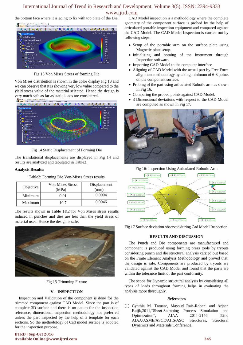
Fig 15 Trimming Fixture
V. INSPECTION
Inspection and Validation of the component is done for the
trimmed component against CAD Model. Since the part is of
complete 3D surface and there is no datum for the inspection
reference, dimensional inspection methodology not preferred
unless the part inspected by the help of a template for each
sections. So the methodology of Cad model surface is adopted
for the inspection purpose.
CAD Model inspection is a methodology where the complete
geometry of the component surface is probed by the help of
articulated portable inspection equipment and compared against
the CAD Model. The CAD Model Inspection is carried out by
following steps.
Setup of the portable arm on the surface plate using
Magnetic plate setup.
Initializing and homing of the instrument through
Inspection software.
Importing CAD Model to the computer interface
Aligning of CAD Model with the actual part by Free Form
alignment methodology by taking minimum of 6-8 points
on the component surface.
Probing of the part using articulated Robotic arm as shown
in Fig 16.
Comparing the probed points against CAD Model.
3 Dimensional deviations with respect to the CAD Model
are computed as shown in Fig 17.
Fig 16: Inspection Using Articulated Robotic Arm
Fig 17 Surface deviation observed during Cad Model Inspection.
RESULTS AND DISCUSSION
The Punch and Die components are manufactured and
component is produced using forming press tools by tryouts
considering punch and die structural analysis carried out based
on the Finite Element Analysis Methodology and proved that,
the design is safe. Components are produced by tryouts are
validated against the CAD Model and found that the parts are
within the tolerance limit of the part conformity.
The scope for Dynamic structural analysis by considering all
types of loads throughout forming helps in evaluating the
analysis more thoroughly.
References
[1] Cynthia M. Tamasc, Masoud Rais-Rohani and Arjaan
Buijk,2011,“Sheet-Stamping Process Simulation and
Optimization”, AIAA 2011-2146, 52nd
AIAA/ASME/ASCE/AHS/ASC Structures, Structural
Dynamics and Materials Conference.

International Journal of Trend in Research and Development, Volume 3(5), ISSN: 2394-9333
www.ijtrd.com
IJTRD | Sep-Oct 2016 Available [email protected] 346
[2] Ulhas K Annigeri, Y P Deepthi, Raghavendra and Ravi
kiran k,2014,” Design, Development and analysis of
forming tool for side panel of an Automobile”, International
Journal of Mechanical and Production engineering,
ISSN:2320-2092, Volume-2, Issue-6.
[3] Kalyani Abhinav and Prof. K. Annamalai, 2013, “Analysis
of sheet metal bending by using Finite Element Method”,
International Journal of Engineering Research &
Technology (IJERT), ISSN: 2278-0181, Vol. 2 Issue 1.
[4] Fundamentals of sheet metal formability by Altair
Engineering Inc.