Analysis of Multi-Band Characteristics of Fractal Shape Antenna
9
International Journal of Innovative Research in Advanced Engineering (IJIRAE) ISSN: 2349-2763 Issue 06, Volume 3 (June 2016) www.ijirae.com __________________________________________________________________________________________________ IJIRAE: Impact Factor Value – SJIF: Innospace, Morocco (2015): 3.361 | PIF: 2.469 | Jour Info: 4.085 | Index Copernicus 2014 = 6.57 © 2014- 16, IJIRAE- All Rights Reserved Page -109 Analysis of Multi-Band Characteristics of Fractal Shape Antenna Priyanka Karhana * Department of Electronics and Communication Engineering Manav Rachna International University, Faridabad Haryana Vimlesh singh Department of Electronics and Communication Engineering Manav Rachna International University, Faridabad Haryana Abstract - This paper put forward the relative study of rectangle shaped Microstrip patch antenna for two different dielectric substrate. If the substrate material’s dielectric constant is escalated, resulting in shrinking /depression of patch antenna. This depression of coordinate is result of back-and-forth in efficiency, bandwidth and impedance. FR4 and RT- Duroid are considered for determine the performances. Feeding technique used is coaxial probe-feed. Measurement like feed-point coordinates, width, length, and ground measurement for each substrate is determined. The model of antenna is performed using the Method of Moments based on IE3D Simulator from Zeland Software Inc, USA. Keyword- Microstrip line, Dielectric, feeding & MOM. I. INTRODUCTION With the tremendous increase in the multimedia and wireless communication services, attracting greater amount of interest in aerospace, radar, satellite communication, defence, missiles and many more. With such wide range of application, its accelerating the pain for the antenna designer’s in providing better form of implementing and designing techniques of microstrip antenna. The patch antenna is beneficial in many ways such as low profile, cost effective, mechnically reboust, light weight, fabrication and analyses is made simple and easy/easily possible, ease of integration into large no of commercial transmitter and reciever. Not only this, wide range of resonance frequency, compact size and radiation pattern helping it to gain immense position in the area of research and development. Microstrip antenna consists of conducting patch of any planar/geometry or non-planar geometry on one side of dielectric substrate with ground plane on other. Patch antenna substantiate(establish) the physical attribution on a substrate have efficient magnetic and physical properties, choosing a right dielectric substate is necessary as well. Modification of substrate material is going to affect the overall account of antenna/antenna’s performance. But In case of deep/thicker substrate, dielectric constant is determined in the lower end of range. Because of better efficiency, greater bandwidth and lax bounded fields into space for radiation, but resulting in increase in patch size. With rise in lower permittivity, frequency and thick substrate, indicating increase in pattern of radiation. To yield greater permittivity patch size should be small. Which in turn reducing radiation efficiency and bandwidth. Thus selection of dielectric substrate plays an atmost important role in designing method of antenna. II. ANTENNA DESIGN The radiating patch can b circular, rectangular, triangular, elliptical, dipole, ring sector etc. Here rectangular form is used over other because of following reasons: due to larger area, greater bandwidth, easy designing, less time required for simulation and slot analysis easier. The rectangular microstrip antenna having dimensions on ground plane as width W, length L and measurement of dielectric materials as width w, length l ,substrate height h and permittivity є. Fabrication technique used is photolithographic(printed circuit) indicating antenna is made amenable and at low cost. Feeding method used here is coaxial probe. Selection of dielectric material The suggestive consideration for selecting dielectric material is losses due to reflection for RF signals Wherever impedance change and from absorption of signal from dielectric material. Following parameter are responsible for selecting the dielectric material: Loss tangent, tan δ Permittivity or relative dielectric constant є Substrate height h Loss tangent, tan δ - it is defined as the processes of measuring the amount/quantity of electromagnetic field passing through dielectric is either absorbs or lost in the dielectric. Applications based on analog/RF are depicted by requiring for less dielectric losses, less and uniform permittivity, less amount of leakages along with low layer counts .therefore material with lower tanδ is choosen and also included in simulation process.
-
Upload
am-publications -
Category
Devices & Hardware
-
view
85 -
download
2
Transcript of Analysis of Multi-Band Characteristics of Fractal Shape Antenna

International Journal of Innovative Research in Advanced Engineering (IJIRAE) ISSN: 2349-2763 Issue 06, Volume 3 (June 2016) www.ijirae.com
__________________________________________________________________________________________________ IJIRAE: Impact Factor Value – SJIF: Innospace, Morocco (2015): 3.361 | PIF: 2.469 | Jour Info: 4.085 |
Index Copernicus 2014 = 6.57 © 2014- 16, IJIRAE- All Rights Reserved Page -109
Analysis of Multi-Band Characteristics of Fractal Shape Antenna
Priyanka Karhana * Department of Electronics and Communication
Engineering Manav Rachna International University,
Faridabad Haryana
Vimlesh singh Department of Electronics and Communication
Engineering Manav Rachna International University,
Faridabad Haryana
Abstract - This paper put forward the relative study of rectangle shaped Microstrip patch antenna for two different dielectric substrate. If the substrate material’s dielectric constant is escalated, resulting in shrinking /depression of patch antenna. This depression of coordinate is result of back-and-forth in efficiency, bandwidth and impedance. FR4 and RT- Duroid are considered for determine the performances. Feeding technique used is coaxial probe-feed. Measurement like feed-point coordinates, width, length, and ground measurement for each substrate is determined. The model of antenna is performed using the Method of Moments based on IE3D Simulator from Zeland Software Inc, USA.
Keyword- Microstrip line, Dielectric, feeding & MOM.
I. INTRODUCTION
With the tremendous increase in the multimedia and wireless communication services, attracting greater amount of interest in aerospace, radar, satellite communication, defence, missiles and many more. With such wide range of application, its accelerating the pain for the antenna designer’s in providing better form of implementing and designing techniques of microstrip antenna. The patch antenna is beneficial in many ways such as low profile, cost effective, mechnically reboust, light weight, fabrication and analyses is made simple and easy/easily possible, ease of integration into large no of commercial transmitter and reciever. Not only this, wide range of resonance frequency, compact size and radiation pattern helping it to gain immense position in the area of research and development. Microstrip antenna consists of conducting patch of any planar/geometry or non-planar geometry on one side of dielectric substrate with ground plane on other. Patch antenna substantiate(establish) the physical attribution on a substrate have efficient magnetic and physical properties, choosing a right dielectric substate is necessary as well. Modification of substrate material is going to affect the overall account of antenna/antenna’s performance. But In case of deep/thicker substrate, dielectric constant is determined in the lower end of range. Because of better efficiency, greater bandwidth and lax bounded fields into space for radiation, but resulting in increase in patch size. With rise in lower permittivity, frequency and thick substrate, indicating increase in pattern of radiation. To yield greater permittivity patch size should be small. Which in turn reducing radiation efficiency and bandwidth. Thus selection of dielectric substrate plays an atmost important role in designing method of antenna.
II. ANTENNA DESIGN
The radiating patch can b circular, rectangular, triangular, elliptical, dipole, ring sector etc. Here rectangular form is used over other because of following reasons: due to larger area, greater bandwidth, easy designing, less time required for simulation and slot analysis easier. The rectangular microstrip antenna having dimensions on ground plane as width W, length L and measurement of dielectric materials as width w, length l ,substrate height h and permittivity є. Fabrication technique used is photolithographic(printed circuit) indicating antenna is made amenable and at low cost. Feeding method used here is coaxial probe. Selection of dielectric material The suggestive consideration for selecting dielectric material is losses due to reflection for RF signals Wherever impedance change and from absorption of signal from dielectric material. Following parameter are responsible for selecting the dielectric material:
Loss tangent, tan δ Permittivity or relative dielectric constant є Substrate height h
Loss tangent, tan δ - it is defined as the processes of measuring the amount/quantity of electromagnetic field passing through dielectric is either absorbs or lost in the dielectric. Applications based on analog/RF are depicted by requiring for less dielectric losses, less and uniform permittivity, less amount of leakages along with low layer counts .therefore material with lower tanδ is choosen and also included in simulation process.

International Journal of Innovative Research in Advanced Engineering (IJIRAE) ISSN: 2349-2763 Issue 06, Volume 3 (June 2016) www.ijirae.com
__________________________________________________________________________________________________ IJIRAE: Impact Factor Value – SJIF: Innospace, Morocco (2015): 3.361 | PIF: 2.469 | Jour Info: 4.085 |
Index Copernicus 2014 = 6.57 © 2014- 16, IJIRAE- All Rights Reserved Page -110
Permittivity or relative dielectric constant є –The permittivity plays an highly important role in effecting antenna’s performance as a whole. Its influence both length and width. Character impedance is affected in case of width whereas in case of length, transmission efficiency is reduced and change in resonant frequency. Larger the permittivity constant signal travelling capacity on a wire reduces, impedance of given geometry reduces and amount of stray capacitance increases along the transmission line. Fringing effect which proved to be the main reason of radiation is also controlled by dielectric constant. Lesser the dielectric constant, greater fringing effect, resulting in better radiation, higher efficiency and bandwidth. Substrate height h – it checks the band width as height is raised, resulting in spurious feed radiation (they are unaccepted radiation and may result in coupling with other components) and surface wave increases thus limiting bandwidth.
III. CALCULATION OF DIMENSION-
In bid to analyze and validate the enhancement for rectangular configuration in microstrip antenna, the expected microstrip antenna method used is- (i) COMPUTATION OF WIDTH (W)-
w
where, c = , = operational frequency, є = permittivity constant of a material (ii) COMPUTATION OF EFFECTIVE DIELECTRIC CONSTANT( ) Effective dielectric constant is responsible for obtaining the fringing fields. Value of effective dielectric constant is considered lower than than permittivity of the substrate as the fringing field in the order of the outside edge of the patch are not restrained inside the dielectric substrate, however also extended in the air. So, its defined as-
= + [1+12 ]-1/2
where, h is height and width is w of substrate material. (iii) COMPUTATION OF LENGTH (L) For narrow band it proved to be an important factor as it determine resonant frequency. The value of length is given by-
= - 2dL
here dL is the length extension and its value can be determined by using equation-
dL= 0.412h
(iv) FEEDING TECHNIQUE USED AND ITS LOCATION
There are four main techniques used coaxial feed, microstrip line feed, proximity coupled feed and aperture coupled feed. The most common and widely used technique is coaxial feed. In this the inner layer is extended from side of dielectric and is soldered to the patch, whereas outer one is linked to ground plane. The core benefit of using coaxial feed is feed can be positioned at any looked-for location to equivalent its input impedance. Thus, increasing return losses, bandwidth and performances. Using following equation one can calculate feed point-
Patch’s width =
Patch’s length

International Journal of Innovative Research in Advanced Engineering (IJIRAE) ISSN: 2349-2763 Issue 06, Volume 3 (June 2016) www.ijirae.com
__________________________________________________________________________________________________ IJIRAE: Impact Factor Value – SJIF: Innospace, Morocco (2015): 3.361 | PIF: 2.469 | Jour Info: 4.085 |
Index Copernicus 2014 = 6.57 © 2014- 16, IJIRAE- All Rights Reserved Page -111
= – dL Here,
=
=
= 90 *
IV. RESULTS AND CONCLUSION
In this paper antenna is simulated for two material: FR-4 and RT-Duroid. The performance of antenna is than compared.
4.1 FR-4(FLAME RESISTANT)
FR-4 is a mark label assigned to glass-reinforced epoxy laminate sheets, rods, printed circuit boards (PCB) and tubes. It is a amalgamated material poised of woven fiberglass cloth in the midst of an epoxy resin binder i.e. flame resistant (self-extinguishing). It is a trendy and multipurpose high-pressure thermo set plastic laminate rating with high-quality strength to weight ratios. In the midst of near zero water absorption, it is used as an electrical insulator possessing having significant mechanical strength. The antenna is designed from a rectangular shape 100mm x 70mm from where the base shape i.e parallelogram of 90mm x 70mm is obtained. Figure 4.1a shows first iteration.
Fig 4.1a: First iteration Fig 4.1b: Second iteration Fig 4.1c: Third iteration
Second iteration is shown in figure 4.1b in which shape is generated within the base shape. Figure 4.1c represent third iteration. For designed fractal shape antenna, Return loss, VSWR & Radiation pattern is analyzed. 4.1.1 SIMULATION RESULTS In this MOM method is used for simulating proposed antenna. Voltage source is 1 volt and frequency range is from 1GHz to 5 GHz. The radiation pattern are shown from fig 1d to 1
Fig 4.1d: Variation of return loss for First iteration

International Journal of Innovative Research in Advanced Engineering (IJIRAE) ISSN: 2349-2763 Issue 06, Volume 3 (June 2016) www.ijirae.com
__________________________________________________________________________________________________ IJIRAE: Impact Factor Value – SJIF: Innospace, Morocco (2015): 3.361 | PIF: 2.469 | Jour Info: 4.085 |
Index Copernicus 2014 = 6.57 © 2014- 16, IJIRAE- All Rights Reserved Page -112
Fig 4.1e: Variation of return loss for Second iteration
Fig 4.1f: Variation of return loss for Third iteration
Fig 4.1g: Variation in VSWR for First iteration
Fig 4.1h: Variation in VSWR for Second iteration

International Journal of Innovative Research in Advanced Engineering (IJIRAE) ISSN: 2349-2763 Issue 06, Volume 3 (June 2016) www.ijirae.com
__________________________________________________________________________________________________ IJIRAE: Impact Factor Value – SJIF: Innospace, Morocco (2015): 3.361 | PIF: 2.469 | Jour Info: 4.085 |
Index Copernicus 2014 = 6.57 © 2014- 16, IJIRAE- All Rights Reserved Page -113
Fig 4.1j: Radiation pattern at 3.30 GHz
Fig 4.1i: Variation in VSWR for Third iteration
Fig 4.1k:: Radiation pattern at 3.13 GHz
International Journal of Innovative Research in Advanced Engineering (IJIRAE) ISSN: 2349-2763 Issue 06, Volume 3 (June 2016) www.ijirae.com
__________________________________________________________________________________________________ IJIRAE: Impact Factor Value – SJIF: Innospace, Morocco (2015): 3.361 | PIF: 2.469 | Jour Info: 4.085 |
Index Copernicus 2014 = 6.57 © 2014- 16, IJIRAE- All Rights Reserved Page -114
Fig 4.1l: Radiation pattern at 2.02 GHz
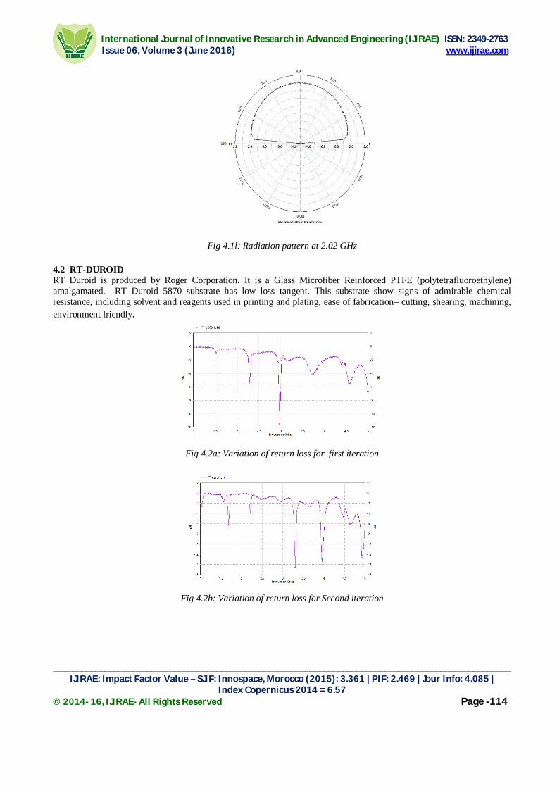
4.2 RT-DUROID RT Duroid is produced by Roger Corporation. It is a Glass Microfiber Reinforced PTFE (polytetrafluoroethylene) amalgamated. RT Duroid 5870 substrate has low loss tangent. This substrate show signs of admirable chemical resistance, including solvent and reagents used in printing and plating, ease of fabrication– cutting, shearing, machining, environment friendly.
Fig 4.2a: Variation of return loss for first iteration
Fig 4.2b: Variation of return loss for Second iteration

International Journal of Innovative Research in Advanced Engineering (IJIRAE) ISSN: 2349-2763 Issue 06, Volume 3 (June 2016) www.ijirae.com
__________________________________________________________________________________________________ IJIRAE: Impact Factor Value – SJIF: Innospace, Morocco (2015): 3.361 | PIF: 2.469 | Jour Info: 4.085 |
Index Copernicus 2014 = 6.57 © 2014- 16, IJIRAE- All Rights Reserved Page -115
Fig 4.2c: Variation of return loss for Third iteration
Fig 4.2d: Variation in VSWR for first iteration
Fig 4.2e: Variation in VSWR for Second iteration
Fig 4.2f: Variation in VSWR for third iteration

International Journal of Innovative Research in Advanced Engineering (IJIRAE) ISSN: 2349-2763 Issue 06, Volume 3 (June 2016) www.ijirae.com
__________________________________________________________________________________________________ IJIRAE: Impact Factor Value – SJIF: Innospace, Morocco (2015): 3.361 | PIF: 2.469 | Jour Info: 4.085 |
Index Copernicus 2014 = 6.57 © 2014- 16, IJIRAE- All Rights Reserved Page -116
Fig 4.2h: Radiation pattern at 3.30 GHz
Fig 4.2g: Radiation pattern at 2.90GHz
Fig 4.2i: Radiation pattern at 2.97GHZ
SUMMARIZING OF RESULTS
PARAMETER
NO. OF RETURN LOSS IN EACH CASES. FR-4 RT-DUROID
FIRST ITERATION 3.3 2.9
SECOND ITERATION 3.13 & 4.6 3.30, 3.90 & 4.9
THIRD ITERATION 2.02 & 4.01 1.7, 2.9, 3.65 & 4.25

International Journal of Innovative Research in Advanced Engineering (IJIRAE) ISSN: 2349-2763 Issue 06, Volume 3 (June 2016) www.ijirae.com
__________________________________________________________________________________________________ IJIRAE: Impact Factor Value – SJIF: Innospace, Morocco (2015): 3.361 | PIF: 2.469 | Jour Info: 4.085 |
Index Copernicus 2014 = 6.57 © 2014- 16, IJIRAE- All Rights Reserved Page -117
Fig: Variation of return loss for third iterationFig: fabricated antenna.
CONCLUSION
Result indicates that the feed location has huge impact on the antenna parameters and by changing them they vary. The fractal concept can be applied to advance the small size antenna’s bandwidth. Also, the projected configuration has small dimensions of 90 x 70mm². It is concluded that it’s a improved antenna for 1-5 GHz range.
REFERENCE
[1]. B.B. Madelbrot, The Fractal Geometry of Nature, New York: W.H. Freeman, 1983. [2]. J.D. Kraus, Antennas, New York: McGraw-Hill (2nd Ed.), 1988. [3]. K.J. Falconer,FractalGeometry:Mathematical Foundations and Applications, New York: Wiley, 1990. [4]. Pozar, D.M.,D.H.Schaubert,"Microstrip Antennas: The Analysis and Design of Microstrip Antennas and
Arrays",New York: IEEE Press, 1995. [5]. N.Cohen, "Fractal Antenna Applications in Wireless Telecomm." in Proc.Professional Program Elect. Industry
Forum, pp. 43-49, 1997. [6]. Yahya Rahmat-Samii and Eric Michielssen, Electromagnetic Optimization by Genetic Algorithms, John Wiley,
1999. [7]. Ramesh Garg, Prakash Bartia, Inder Bahl, Apisak Ittipiboon, “Microstrip Antenna Design Handbook’’, Artech
House Inc. Norwood, MA, pp 168, 253-316, 2001. [8]. C.A.Balanis,"Antenna Theory Analysis and Design", 3rd ed., Hoboken, New Jersey:Wiley, 2005. [9]. J. Anguera, A. Cabedo, C. Picher, I. Sanz, M. RiM, and C.Puente, "Multiband handset antennas by means of ground
plane modification," presented at the IEEE Antennas Propag. Society Int.Symp., Honolulu, HI, Jun. 2007.
TESTED RESULT FOR THIRD ITERATION
FR-4
1.84, 2.36, 2.99, 3.15 & 4.25