Analysis of Knuckle Joint of Various Materials using CAE · PDF filecontain threaded joints,...
8
International Journal of Engineering Technology, Management and Applied Sciences www.ijetmas.com January 2017, Volume 5, Issue 1, ISSN 2349-4476 45 Nipun Kumar, Dr. Gian Bhushan, Dr. Pankaj Chandna Analysis of Knuckle Joint of Various Materials using CAE Tools Nipun Kumar M.Tech Student Dept. of mechanical Engg. NIT, Kurukshetra Dr. Gian Bhushan Professor Dept. of mechanical engg. NIT, Kurukshetra Dr. Pankaj Chandna Professor Dept. of mechanical engg. NIT, Kurukshetra ABSTRACT A knuckle joint is used to connect two rods or bars when a small amount of angular movement is necessary. The load subjected to the rods is tensile but if joint is guided the rods may support a compressive load. This joint is commonly used where it is required to have joint that can be readily disconnected for repair. In the present work knuckle joint made of stainless steel, gray cast iron magnesium, aluminium, stainless steel, structural steel and gray cast iron has been analyzed for stress and deformation under different loading conditions. The CAD model of knuckle joint is made in CATIA V5 R20 and analyzed in ANSYS 15. It has been observed that stresses developed for knuckle joint made of magnesium are least and the knuckle joint made of aluminium can sustain maximum tensile load without failure. Keywords Knuckle Joint, CATIA, ANSYS I. INTRODUCTION In mechanical and automobile industry fasteners play an important role. Fasteners are of two types. They are permanent or temporary. Permanent fasteners contain riveted joints and welded joints. Temporary fasteners contain threaded joints, cotter joint and knuckle joint. The knuckle joint is a type of mechanical joint which is used to connect two rods or bars when a small amount of flexibility or angular moment is necessary. The rods connected by this joint are subjected to tensile loads, although if the rods are guided, they may support compressive loads as well [1, 2].Knuckle joints find a wide variety of applications in links of suspension chain, tractors, tie rod joints for roof truss, cranes, robotics joints, rod connections of various types etc. The knuckle joint may be failed on three modes shear, crushing and in tension. Robert c. juvinall and Kurt M. Marshek [3] stated in static failure theory that whatever is responsible for failure in standard tensile test will also be responsible for failure under all other conditions of static loading. Purushottam Dumbre et al [4] focused on structural analysis of steering knuckle for weight reduction. The finite element software hyperworks was used to achieve the result. The targeted weight or mass reduction for this exercise was about 5% without compromising on the structural strength.Pantazopoulos et.al [5] studied the failure of a knuckle joint of a universal coupling system. It was mentioned that torsional overload of the knuckle joint is the major cause of failure. Ravindra S.Dharpure [6] studiedfailure of the knuckle pin in a railway coupling due to shearing. It was found that a proper elastic material can be used instead of steel for pin of knuckle joint for deformability of 5 mm. Swati N. Datey et al [7] focused on finite element analysis of universal joint. Analysis of rigid flange coupling was carried out which was similar to the universal joint. In this analysis ANSYS software was used to find different torques and it was verified by manual calculation.Karishma Chaurasia[8] studied non parametric shape optimization of knuckle jointfor different materials using finite element analysis. It was found that with the help of shape optimization light weight rigid design for knuckle joint could be developed resulting in reducing the mass of knuckle joint. In the present research work knuckle joint made of
Transcript of Analysis of Knuckle Joint of Various Materials using CAE · PDF filecontain threaded joints,...
International Journal of Engineering Technology, Management and Applied Sciences
www.ijetmas.com January 2017, Volume 5, Issue 1, ISSN 2349-4476
45 Nipun Kumar, Dr. Gian Bhushan, Dr. Pankaj Chandna
Analysis of Knuckle Joint of Various Materials using CAE
Tools
Nipun Kumar
M.Tech Student
Dept. of mechanical Engg.
NIT, Kurukshetra
Dr. Gian Bhushan
Professor
Dept. of mechanical engg.
NIT, Kurukshetra
Dr. Pankaj Chandna
Professor
Dept. of mechanical engg.
NIT, Kurukshetra
ABSTRACT
A knuckle joint is used to connect two rods or bars when a small amount of angular movement is necessary. The load
subjected to the rods is tensile but if joint is guided the rods may support a compressive load. This joint is commonly
used where it is required to have joint that can be readily disconnected for repair. In the present work knuckle joint made
of stainless steel, gray cast iron magnesium, aluminium, stainless steel, structural steel and gray cast iron has been
analyzed for stress and deformation under different loading conditions. The CAD model of knuckle joint is made in
CATIA V5 R20 and analyzed in ANSYS 15. It has been observed that stresses developed for knuckle joint made of
magnesium are least and the knuckle joint made of aluminium can sustain maximum tensile load without failure.
Keywords
Knuckle Joint, CATIA, ANSYS
I. INTRODUCTION
In mechanical and automobile industry fasteners play an important role. Fasteners are of two types. They are
permanent or temporary. Permanent fasteners contain riveted joints and welded joints. Temporary fasteners
contain threaded joints, cotter joint and knuckle joint. The knuckle joint is a type of mechanical joint which is
used to connect two rods or bars when a small amount of flexibility or angular moment is necessary. The rods
connected by this joint are subjected to tensile loads, although if the rods are guided, they may support
compressive loads as well [1, 2].Knuckle joints find a wide variety of applications in links of suspension
chain, tractors, tie rod joints for roof truss, cranes, robotics joints, rod connections of various types etc. The
knuckle joint may be failed on three modes shear, crushing and in tension. Robert c. juvinall and Kurt M.
Marshek [3] stated in static failure theory that whatever is responsible for failure in standard tensile test will
also be responsible for failure under all other conditions of static loading. Purushottam Dumbre et al [4]
focused on structural analysis of steering knuckle for weight reduction. The finite element software
hyperworks was used to achieve the result. The targeted weight or mass reduction for this exercise was about
5% without compromising on the structural strength.Pantazopoulos et.al [5] studied the failure of a knuckle
joint of a universal coupling system. It was mentioned that torsional overload of the knuckle joint is the major
cause of failure. Ravindra S.Dharpure [6] studiedfailure of the knuckle pin in a railway coupling due to
shearing. It was found that a proper elastic material can be used instead of steel for pin of knuckle joint for
deformability of 5 mm. Swati N. Datey et al [7] focused on finite element analysis of universal joint. Analysis
of rigid flange coupling was carried out which was similar to the universal joint. In this analysis ANSYS
software was used to find different torques and it was verified by manual calculation.Karishma Chaurasia[8]
studied non parametric shape optimization of knuckle jointfor different materials using finite element analysis.
It was found that with the help of shape optimization light weight rigid design for knuckle joint could be
developed resulting in reducing the mass of knuckle joint. In the present research work knuckle joint made of
International Journal of Engineering Technology, Management and Applied Sciences
www.ijetmas.com January 2017, Volume 5, Issue 1, ISSN 2349-4476
46 Nipun Kumar, Dr. Gian Bhushan, Dr. Pankaj Chandna
various materials like magnesium, aluminium alloy, stainless steel, structural steel and gray cast iron has been
analyzed for stresses developed and deformation using computer aided engineering tools.
II. CAD MODELLING
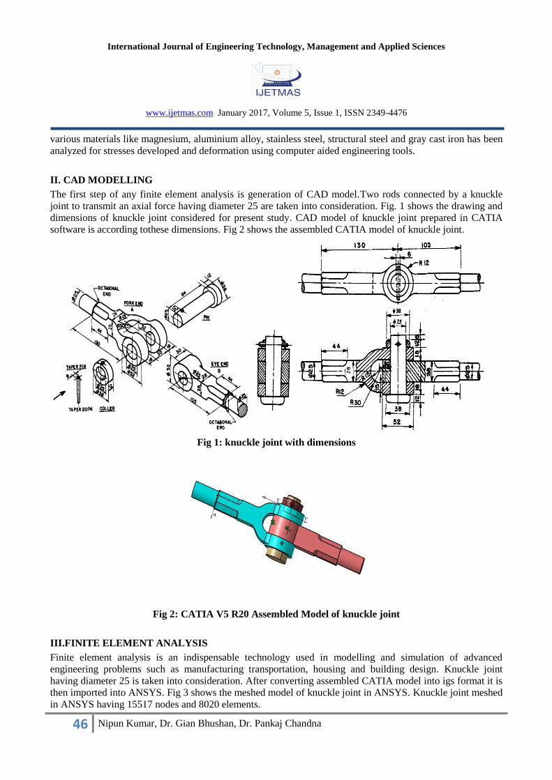
The first step of any finite element analysis is generation of CAD model.Two rods connected by a knuckle
joint to transmit an axial force having diameter 25 are taken into consideration. Fig. 1 shows the drawing and
dimensions of knuckle joint considered for present study. CAD model of knuckle joint prepared in CATIA
software is according tothese dimensions. Fig 2 shows the assembled CATIA model of knuckle joint.
Fig 1: knuckle joint with dimensions
Fig 2: CATIA V5 R20 Assembled Model of knuckle joint
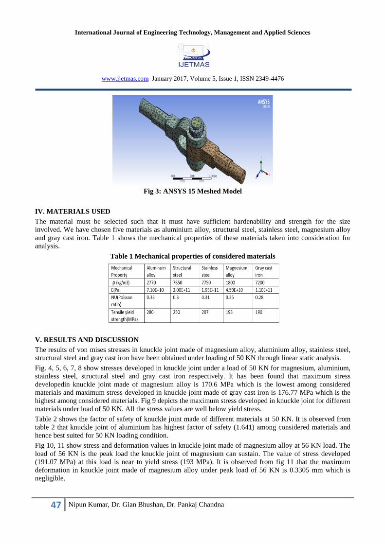
III.FINITE ELEMENT ANALYSIS
Finite element analysis is an indispensable technology used in modelling and simulation of advanced
engineering problems such as manufacturing transportation, housing and building design. Knuckle joint
having diameter 25 is taken into consideration. After converting assembled CATIA model into igs format it is
then imported into ANSYS. Fig 3 shows the meshed model of knuckle joint in ANSYS. Knuckle joint meshed
in ANSYS having 15517 nodes and 8020 elements.
International Journal of Engineering Technology, Management and Applied Sciences
www.ijetmas.com January 2017, Volume 5, Issue 1, ISSN 2349-4476
47 Nipun Kumar, Dr. Gian Bhushan, Dr. Pankaj Chandna
Fig 3: ANSYS 15 Meshed Model
IV. MATERIALS USED
The material must be selected such that it must have sufficient hardenability and strength for the size
involved. We have chosen five materials as aluminium alloy, structural steel, stainless steel, magnesium alloy
and gray cast iron. Table 1 shows the mechanical properties of these materials taken into consideration for
analysis.
Table 1 Mechanical properties of considered materials
V. RESULTS AND DISCUSSION
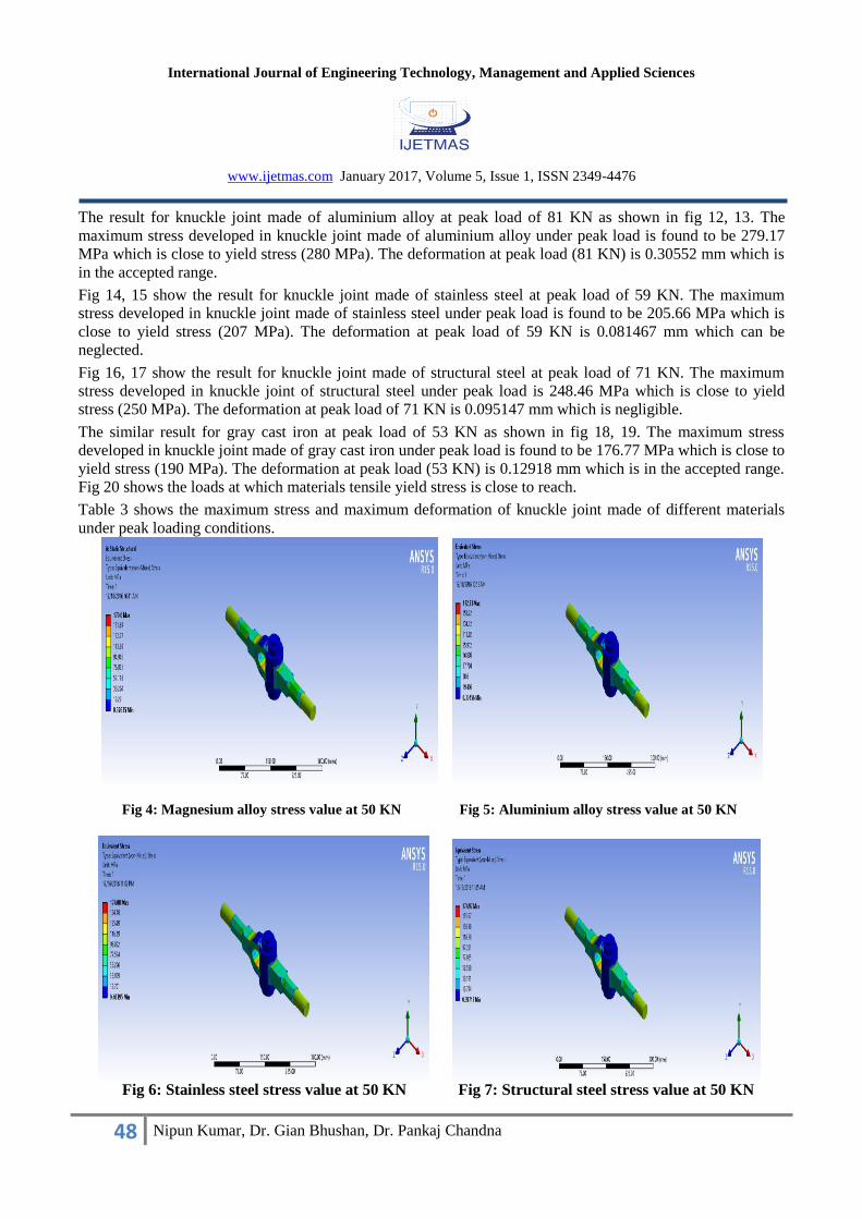
The results of von mises stresses in knuckle joint made of magnesium alloy, aluminium alloy, stainless steel,
structural steel and gray cast iron have been obtained under loading of 50 KN through linear static analysis.
Fig. 4, 5, 6, 7, 8 show stresses developed in knuckle joint under a load of 50 KN for magnesium, aluminium,
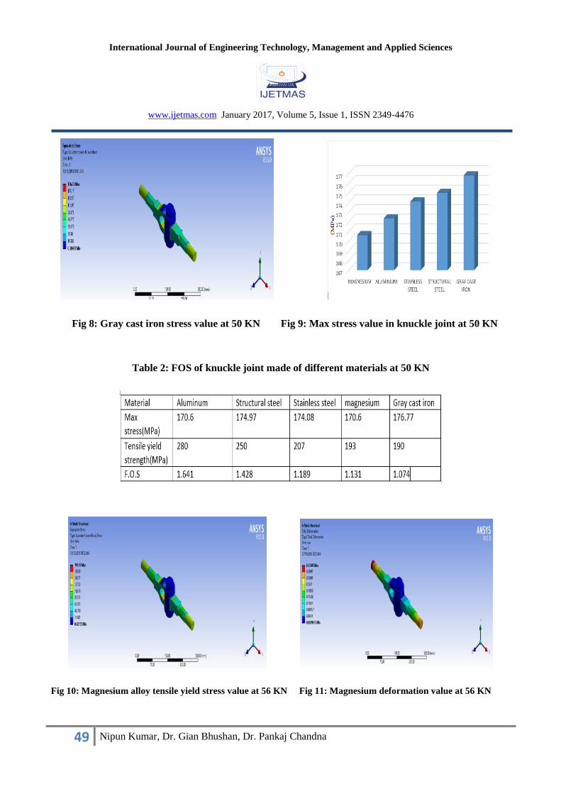
stainless steel, structural steel and gray cast iron respectively. It has been found that maximum stress
developedin knuckle joint made of magnesium alloy is 170.6 MPa which is the lowest among considered
materials and maximum stress developed in knuckle joint made of gray cast iron is 176.77 MPa which is the
highest among considered materials. Fig 9 depicts the maximum stress developed in knuckle joint for different
materials under load of 50 KN. All the stress values are well below yield stress.
Table 2 shows the factor of safety of knuckle joint made of different materials at 50 KN. It is observed from
table 2 that knuckle joint of aluminium has highest factor of safety (1.641) among considered materials and
hence best suited for 50 KN loading condition.
Fig 10, 11 show stress and deformation values in knuckle joint made of magnesium alloy at 56 KN load. The
load of 56 KN is the peak load the knuckle joint of magnesium can sustain. The value of stress developed
(191.07 MPa) at this load is near to yield stress (193 MPa). It is observed from fig 11 that the maximum
deformation in knuckle joint made of magnesium alloy under peak load of 56 KN is 0.3305 mm which is
negligible.
International Journal of Engineering Technology, Management and Applied Sciences
www.ijetmas.com January 2017, Volume 5, Issue 1, ISSN 2349-4476
48 Nipun Kumar, Dr. Gian Bhushan, Dr. Pankaj Chandna
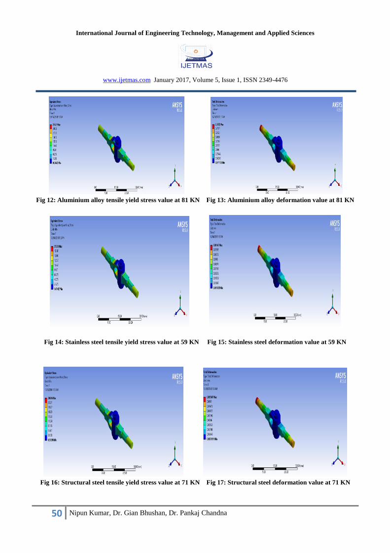
The result for knuckle joint made of aluminium alloy at peak load of 81 KN as shown in fig 12, 13. The
maximum stress developed in knuckle joint made of aluminium alloy under peak load is found to be 279.17
MPa which is close to yield stress (280 MPa). The deformation at peak load (81 KN) is 0.30552 mm which is
in the accepted range.
Fig 14, 15 show the result for knuckle joint made of stainless steel at peak load of 59 KN. The maximum
stress developed in knuckle joint made of stainless steel under peak load is found to be 205.66 MPa which is
close to yield stress (207 MPa). The deformation at peak load of 59 KN is 0.081467 mm which can be
neglected.
Fig 16, 17 show the result for knuckle joint made of structural steel at peak load of 71 KN. The maximum
stress developed in knuckle joint of structural steel under peak load is 248.46 MPa which is close to yield
stress (250 MPa). The deformation at peak load of 71 KN is 0.095147 mm which is negligible.
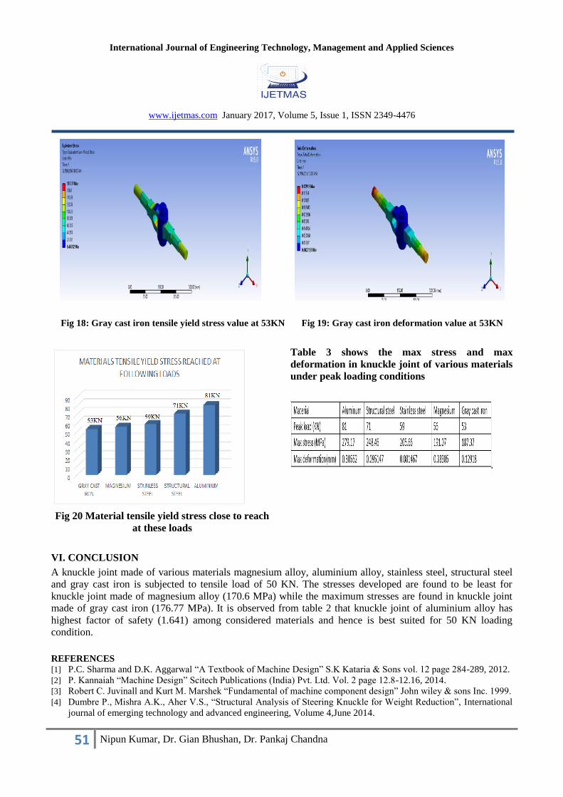
The similar result for gray cast iron at peak load of 53 KN as shown in fig 18, 19. The maximum stress
developed in knuckle joint made of gray cast iron under peak load is found to be 176.77 MPa which is close to
yield stress (190 MPa). The deformation at peak load (53 KN) is 0.12918 mm which is in the accepted range.
Fig 20 shows the loads at which materials tensile yield stress is close to reach.
Table 3 shows the maximum stress and maximum deformation of knuckle joint made of different materials
under peak loading conditions.
Fig 4: Magnesium alloy stress value at 50 KN Fig 5: Aluminium alloy stress value at 50 KN
Fig 6: Stainless steel stress value at 50 KN Fig 7: Structural steel stress value at 50 KN
International Journal of Engineering Technology, Management and Applied Sciences
www.ijetmas.com January 2017, Volume 5, Issue 1, ISSN 2349-4476
49 Nipun Kumar, Dr. Gian Bhushan, Dr. Pankaj Chandna
Fig 8: Gray cast iron stress value at 50 KN Fig 9: Max stress value in knuckle joint at 50 KN
Table 2: FOS of knuckle joint made of different materials at 50 KN
Fig 10: Magnesium alloy tensile yield stress value at 56 KN Fig 11: Magnesium deformation value at 56 KN
International Journal of Engineering Technology, Management and Applied Sciences
www.ijetmas.com January 2017, Volume 5, Issue 1, ISSN 2349-4476
50 Nipun Kumar, Dr. Gian Bhushan, Dr. Pankaj Chandna
Fig 12: Aluminium alloy tensile yield stress value at 81 KN Fig 13: Aluminium alloy deformation value at 81 KN
Fig 14: Stainless steel tensile yield stress value at 59 KN Fig 15: Stainless steel deformation value at 59 KN
Fig 16: Structural steel tensile yield stress value at 71 KN Fig 17: Structural steel deformation value at 71 KN
International Journal of Engineering Technology, Management and Applied Sciences
www.ijetmas.com January 2017, Volume 5, Issue 1, ISSN 2349-4476
51 Nipun Kumar, Dr. Gian Bhushan, Dr. Pankaj Chandna
Fig 18: Gray cast iron tensile yield stress value at 53KN Fig 19: Gray cast iron deformation value at 53KN
Fig 20 Material tensile yield stress close to reach
at these loads
Table 3 shows the max stress and max
deformation in knuckle joint of various materials
under peak loading conditions
VI. CONCLUSION
A knuckle joint made of various materials magnesium alloy, aluminium alloy, stainless steel, structural steel
and gray cast iron is subjected to tensile load of 50 KN. The stresses developed are found to be least for
knuckle joint made of magnesium alloy (170.6 MPa) while the maximum stresses are found in knuckle joint
made of gray cast iron (176.77 MPa). It is observed from table 2 that knuckle joint of aluminium alloy has
highest factor of safety (1.641) among considered materials and hence is best suited for 50 KN loading
condition.
REFERENCES
[1] P.C. Sharma and D.K. Aggarwal “A Textbook of Machine Design” S.K Kataria & Sons vol. 12 page 284-289, 2012.
[2] P. Kannaiah “Machine Design” Scitech Publications (India) Pvt. Ltd. Vol. 2 page 12.8-12.16, 2014.
[3] Robert C. Juvinall and Kurt M. Marshek “Fundamental of machine component design” John wiley & sons Inc. 1999.
[4] Dumbre P., Mishra A.K., Aher V.S., “Structural Analysis of Steering Knuckle for Weight Reduction”, International
journal of emerging technology and advanced engineering, Volume 4,June 2014.
International Journal of Engineering Technology, Management and Applied Sciences
www.ijetmas.com January 2017, Volume 5, Issue 1, ISSN 2349-4476
52 Nipun Kumar, Dr. Gian Bhushan, Dr. Pankaj Chandna
[5] G. Pantazopoulos, A Sampani E. Tsagaridis “Torsional failure of a knuckle joint of a universal steel coupling system
during operation” Engineering failure analysis, vol. 14, issue 1, ISSN1350-6307.
[6] Ravindra S. Dharpure, Prof D. M. Mate, “Study and Analysis of Pin of Knuckle Joint in Train” JETIR, Volume 1
Issue 3, (ISSN-2349-5162).
[7] Swati N. Datey “Finite Element Analysis of Universal Joint”, IOSR Journal of Mechanical and Civil Engineering
(IOSR-JMCE), Volume 11, pp. 64-69.
[8] Karishma Chaurasia “Non Parametric Shape Optimization of Knuckle Joint for different Materials using Finite
Element Analysis” Journal of Material Science and Mechanical Engineering (JMSME) ISSN: 2393-9109; Volume 2,
Number 2; January-March, 2015 pp. 178-183.
[9] Stuart B.H “Tribological studies of composite material” Tribology International, 31,647-651(1998)