Analysis of Interworking Architectures for IP Multimedia ...vincentw/T/Munir.pdf · Analysis of...
107
Analysis of Interworking Architectures for IP Multimedia Subsystem by Arslan Munir B.Sc., Electrical Engineering, University of Engineering and Technology, Lahore, 2004 A THESIS SUBMITTED IN PARTIAL FULFILMENT OF THE REQUIREMENTS FOR THE DEGREE OF Master of Applied Science in The Faculty of Graduate Studies (in Electrical and Computer Engineering) The University of British Columbia April 2007 c Arslan Munir 2007
Transcript of Analysis of Interworking Architectures for IP Multimedia ...vincentw/T/Munir.pdf · Analysis of...

Analysis of InterworkingArchitectures for IP Multimedia
Subsystemby
Arslan Munir
B.Sc., Electrical Engineering, University of Engineering and Technology,Lahore, 2004
A THESIS SUBMITTED IN PARTIAL FULFILMENT OFTHE REQUIREMENTS FOR THE DEGREE OF
Master of Applied Science
in
The Faculty of Graduate Studies
(in Electrical and Computer Engineering)
The University of British Columbia
April 2007
c© Arslan Munir 2007
In presenting this thesis in partial fulfilment of the requirements for an advanceddegree at the University of British Columbia, I agree that the Library shall make it freelyavailable for reference and study. I further agree that permission for extensive copyingof this thesis for scholarly purposes may be granted by the head of my department or byhis or her representatives. It is understood that copying or publication of this thesis forfinancial gain shall not be allowed without my written permission.
(Signature)
Electrical and Computer Engineering
The University of British ColumbiaVancouver, Canada
Date

Abstract
The future fourth generation wireless heterogeneous networks aim to integrate various
wireless access technologies and to support the IMS (IP multimedia subsystem) ses-
sions. In the first part of this thesis, we propose the Loosely Coupled Satellite-Cellular-
WiMax-WLAN (LCSCW2) and the Tightly Coupled Satellite-Cellular-WiMax-WLAN
(TCSCW2) interworking architectures. The LCSCW2 and TCSCW2 architectures use
the loosely coupling and tightly coupling approach respectively and both of them integrate
the satellite networks, 3rd generation (3G) wireless networks, worldwide interoperabil-
ity for microwave access (WiMax), and wireless local area networks (WLANs). They
can support IMS sessions and provide global coverage. The LCSCW2 architecture facil-
itates independent deployment and traffic engineering of various access networks. The
TCSCW2 can guarantee quality of service (QoS) to a certain extent. We also propose
an analytical model to determine the associate cost for the signaling and data traffic
for inter-system communication in the LCSCW2 and TCSCW2 architectures. The cost
analysis includes the transmission, processing, and queueing costs at various entities. Nu-
merical results are presented for different arrival rates and session lengths. In the second
part of this thesis, the signaling flows for IMS registration, IMS session establishment
ii

Abstract
and IMS session re-establishment procedure after undergoing a vertical handoff in a 4G
environment are analyzed. Signaling delays are calculated for IMS signaling taking into
account transmission, processing and queueing delays at network entities. The proposed
analysis of the IMS signaling flows is independent of a particular access network tech-
nology and interworking architecture and can be applied to any of the access network
technology and 4G interworking architecture.
iii
Table of Contents
Abstract . . . . . . . . . . . . . . . . . . . . . . . . . . . . . . . . . . . . . . . . ii
Table of Contents . . . . . . . . . . . . . . . . . . . . . . . . . . . . . . . . . . iv
List of Tables . . . . . . . . . . . . . . . . . . . . . . . . . . . . . . . . . . . . vii
List of Figures . . . . . . . . . . . . . . . . . . . . . . . . . . . . . . . . . . . . viii
List of Acronyms . . . . . . . . . . . . . . . . . . . . . . . . . . . . . . . . . . x
Acknowledgements . . . . . . . . . . . . . . . . . . . . . . . . . . . . . . . . . xvii
1 Introduction . . . . . . . . . . . . . . . . . . . . . . . . . . . . . . . . . . . 1
1.1 Motivations . . . . . . . . . . . . . . . . . . . . . . . . . . . . . . . . . . 2
1.2 Contributions . . . . . . . . . . . . . . . . . . . . . . . . . . . . . . . . . 2
1.3 Structure of the Thesis . . . . . . . . . . . . . . . . . . . . . . . . . . . 4
2 Related Work . . . . . . . . . . . . . . . . . . . . . . . . . . . . . . . . . . 5
2.1 Literature Survey . . . . . . . . . . . . . . . . . . . . . . . . . . . . . . 5
2.2 Discussions . . . . . . . . . . . . . . . . . . . . . . . . . . . . . . . . . . 12
iv

Table of Contents
2.3 4G Interworking Architectures . . . . . . . . . . . . . . . . . . . . . . . 15
2.3.1 Tightly Coupled (TC) Interworking Architecture . . . . . . . . . 16
2.3.2 Loosely Coupled (LC) Interworking Architecture . . . . . . . . . 18
2.3.3 Hybrid Coupled (HC) Interworking Architecture . . . . . . . . . 19
2.3.4 The TCDRAS Interworking Architecture . . . . . . . . . . . . . 22
2.3.5 The LCDRAS Interworking Architecture . . . . . . . . . . . . . . 22
3 LCSCW2 and TCSCW2: Architectures for IP Multimedia Subsystem 24
3.1 The LCSCW2 Architecture . . . . . . . . . . . . . . . . . . . . . . . . . 25
3.2 The TCSCW2 Architecture . . . . . . . . . . . . . . . . . . . . . . . . . 28
3.3 An Analytical Model for Cost Analysis . . . . . . . . . . . . . . . . . . . 33
3.3.1 Available Paths for Communications . . . . . . . . . . . . . . . . 34
3.3.2 Transmission Cost . . . . . . . . . . . . . . . . . . . . . . . . . . 36
3.3.3 Processing Cost . . . . . . . . . . . . . . . . . . . . . . . . . . . 37
3.3.4 Queueing Cost . . . . . . . . . . . . . . . . . . . . . . . . . . . . 39
3.4 Numerical Results . . . . . . . . . . . . . . . . . . . . . . . . . . . . . . 41
3.5 Summary . . . . . . . . . . . . . . . . . . . . . . . . . . . . . . . . . . . 48
4 Analysis of SIP-based Signaling for IMS Sessions in 4G Networks . 49
4.1 Delay Analysis of IMS Signaling Procedures . . . . . . . . . . . . . . . . 50
4.1.1 Transmission Delay . . . . . . . . . . . . . . . . . . . . . . . . . 51
4.1.2 Processing Delay . . . . . . . . . . . . . . . . . . . . . . . . . . . 59
v

Table of Contents
4.1.3 Queueing Delay . . . . . . . . . . . . . . . . . . . . . . . . . . . 61
4.1.4 Total Delay . . . . . . . . . . . . . . . . . . . . . . . . . . . . . . 63
IMS Registration Procedure Delay . . . . . . . . . . . . . . . . . 64
IMS Session Setup Delay . . . . . . . . . . . . . . . . . . . . . . 64
IMS Session Re-establishment Delay . . . . . . . . . . . . . . . . 65
4.2 Numerical Results . . . . . . . . . . . . . . . . . . . . . . . . . . . . . . 66
4.3 Summary . . . . . . . . . . . . . . . . . . . . . . . . . . . . . . . . . . . 71
Bibliography . . . . . . . . . . . . . . . . . . . . . . . . . . . . . . . . . . . . . 82
vi

List of Tables
4.1 Size of SIP messages involved in IMS signaling . . . . . . . . . . . . . . . 54
4.2 Values of K for signaling messages in different channel rates . . . . . . . 56
vii
List of Figures
2.1 Tightly Coupled interworking architecture . . . . . . . . . . . . . . . . . 17
2.2 Loosely Coupled interworking architecture . . . . . . . . . . . . . . . . . 18
2.3 Hybrid Coupled interworking architecture . . . . . . . . . . . . . . . . . 20
2.4 The TCDRAS interworking architecture . . . . . . . . . . . . . . . . . . 21
2.5 The LCDRAS interworking architecture . . . . . . . . . . . . . . . . . . 23
3.1 The LCSCW2 interworking architecture. . . . . . . . . . . . . . . . . . . 25
3.2 The TCSCW2 interworking architecture . . . . . . . . . . . . . . . . . . 29
3.3 Signaling and data communication paths in the LCSCW2 architecture. . 34
3.4 Signaling and data communication paths in the TCSCW2 architecture. . 35
3.5 The breakup of system signaling cost in the LCSCW2 architecture. . . . 43
3.6 The breakup of system signaling cost in the TCSCW2 architecture. . . . 44
3.7 Effect of varying arrival rate on system signaling cost. . . . . . . . . . . . 45
3.8 Effect of varying arrival rate on system data cost. . . . . . . . . . . . . . 46
3.9 Effect of varying session duration on system data cost. . . . . . . . . . . 47
4.1 GPRS attach procedure. . . . . . . . . . . . . . . . . . . . . . . . . . . . 57
viii
List of Figures
4.2 PDP context activation procedure. . . . . . . . . . . . . . . . . . . . . . 72
4.3 DHCP registration process. . . . . . . . . . . . . . . . . . . . . . . . . . 72
4.4 IMS registration process. . . . . . . . . . . . . . . . . . . . . . . . . . . . 73
4.5 IMS session setup procedure . . . . . . . . . . . . . . . . . . . . . . . . . 74
4.6 IMS registration for fixed λ and p . . . . . . . . . . . . . . . . . . . . . . 75
4.7 Session setup when SN is in 3G and CN is in WLAN for fixed λ and p . . 75
4.8 Session setup when SN and CN are in 3G for fixed λ and p . . . . . . . . 76
4.9 Session setup when SN and CN are in WLAN for fixed λ and p . . . . . 76
4.10 Session re-establishment when SN in 3G and CN in WLAN for fixed λ and p 77
4.11 Session re-establishment when SN and CN are in 3G for fixed λ and p . . 77
4.12 Session re-establishment when SN in WLAN and CN in 3G for fixed λ and p 78
4.13 Session re-establishment when SN and CN are in WLAN for fixed λ and p 78
4.14 Effect of changing λ on IMS registration delay for fixed p . . . . . . . . . 79
4.15 Effect of changing λ on IMS session setup delay for fixed p . . . . . . . . 79
4.16 Effect of changing λ on IMS session re-establishment delay for fixed p . . 80
4.17 Effect of changing p on IMS registration delay for fixed λ . . . . . . . . . 80
4.18 Effect of changing p on IMS session setup delay for fixed λ . . . . . . . . 81
4.19 Effect of changing p on IMS session re-establishment delay for fixed λ . . 81
ix
List of Acronyms
3G Third Generation
3GPP 3rd Generation Partnership Project
AAA Authentication, Authorization and Account-
ing
AN Access Network
AP Access Point
ARG Access Router and Gateway
AS Access Stratum
BER Bit Error Rate
BS Base Station
BSC Base Station Controller
CBR Constant Bit Rate
CDMA Code Division Multiple Access
x

List of Acronyms
CN Correspondent Node
DAD Duplicate Address Detection
DHCP Dynamic Host Configuration Protocol
DNS Domain Name System
DS Differentiated Services
DSCP Differentiated Services Code Point
EAP Extensible Authentication Protocol
EIR Equipment Identification Register
GHSN Gateway Hotspot network Support Node
GGSN Gateway GPRS Support Node
GPRS General Packet Radio Service
GSM Global System for Mobile Communications
HARQ Hybrid Automatic Request
HC Hybrid Coupled
HCSCW2 Hybrid Coupled Satellite-Cellular-WiMax-WLAN
HLR Home Location Register
xi

List of Acronyms
HNAC Hotspot Network Area Controller
HSS Home Subscriber Server
I-CSCF Interrogating-Call Session Control Function
IETF Internet Engineering Task Force
IM Island Manager
IMS IP Multimedia Subsystem
IP Internet Protocol
IPSec IP Security
ISDN Integrated Services Digital Network
ISL Inter-Satellite Link
ISUP ISDN User Part
LCDRAS Loosely Coupled with Direct Radio Access Sys-
tem
LCSCW2 Loosely Coupled Satellite-Cellular-WiMax-WLAN
MAC Medium Access Control
MGCF Media Gateway Control Function
xii

List of Acronyms
MGW Media Gateway
MT Mobile Terminal
NAS Non Access Stratum
NAT Network Address Translation
OBP On-board Processing
PCF Packet Control Function
PCS Personal Communication Services
P-CSCF Proxy-Call Session Control Function
PDCH Packet Data Channels
PDG Packet Data Gateway
PDP Packet Data Protocol
PDSN Packet Data Serving Node
PDU Packet Data Unit
PIM-SM Protocol-Independent Multicast Sparse Mode
PLMN Public Land Mobile Network
PS Packet Switched
xiii

List of Acronyms
PSTN Public Switched Telephone Network
QoS Quality of Service
RA Routing Area
RB Radio Bearer
RLC-AM Radio Link Control-Acknowledged Mode
RNC Radio Network Controller
RTO Retransmission Time Out
RTT Round Trip Time
R-UIM Removable-User Identity Module
S3GIF Satellite-3G Interworking Function
SigComp Signaling Compression
S-CSCF Serving-Call Session Control Function
SFES Satellite Fixed Earth Station
SGSN Serving GPRS Support Node
SGW Signaling Gateway
SIM Subscriber Identity Module
xiv

List of Acronyms
SIP Session Initiation Protocol
SLA Service Level Agreement
SMS Short Messaging Service
SN Source Node
SS7 Signaling System Number 7
SSB Satellite Spot Beam
S-UMTS Satellite-UMTS
TC Tightly Coupled
TCDRAS Tightly Coupled with Direct Radio Access Sys-
tem
TCP Transmission Control Protocol
TCSCW2 Tightly Coupled Satellite-Cellular-WiMax-WLAN
TE Terminal Equipment
ToS Type of Service
UDP User Datagram Protocol
UE User Equipment
xv
List of Acronyms
UMTS Universal Mobile Telecommunications System
USIM Universal Subscriber Identity Module
VBR Variable Bit Rate
VoIP Voice over IP
WGDCT WLAN to 3G Direct Controller and Transceiver
WAG Wireless Access Gateway
WBSC WiMax Base Station Controller
WiMax Worldwide Interoperability for Microwave Ac-
cess
WIF WLAN-3G Interworking Function
WLAN Wireless Local Area Network
WMIF WiMax-3G Interworking Function
WNC WiMax Network Controller
xvi
Acknowledgements
I would like to express my sincere gratitude to my graduate supervisor Dr. Vincent
Wong for his guidance and support during the course of my graduate studies. I sincerely
appreciate the considerable amount of time and effort he invested in helping me with
my research and thesis. I would like to thank my fellow colleagues, particularly Syed
Hussain Ali, Enrique Stevens-Navarro, and Ehsan Bayaki, who have provided helpful
suggestions along the way. I also acknowledge Dr. Vikram Krishnamurthy whose guidance
and suggestions helped me to improve the overall horizon of my knowledge.
This work is supported by Bell Canada and Natural Sciences and Engineering Re-
search Council of Canada under project grant 328202-05.
xvii

Chapter 1
Introduction
The 4th generation (4G) wireless heterogeneous networks are envisioned as the integra-
tion of various wireless access technologies such as wireless local area network (WLAN),
3rd generation (3G) technologies including universal mobile telecommunications system
(UMTS) and code division multiple access (CDMA) based CDMA2000 system, worldwide
interoperability for microwave access (WiMax), and satellite networks. The aim behind
this integration is to provide the users with global coverage and to provide the users with
the capability to switch between different available access networks (ANs). The success
of the 4G wireless heterogeneous networks depends on the successful integration of the
currently available ANs.
The IP multimedia subsystem (IMS) is standardized by the 3rd generation partner-
ship project (3GPP) and 3GPP2 as a new core network domain [1]. The IMS enables
the provision of internet protocol (IP) based multimedia applications to mobile users,
guarantees quality of service (QoS) across different AN technologies and permits service
providers to charge according to different policies. In addition, the IMS enables third-
party vendors to develop new applications for operators and users. A growing number
of telecommunication vendors are beginning to release devices and services based on the
1

Chapter 1. Introduction
IMS [2].
1.1 Motivations
Although, some 4G interworking architectures have been proposed before which integrate
3G and WLAN or 3G and satellite networks or 3G and WiMax individually, to the best
of our knowledge, a 4G interworking architecture that integrates satellite, WiMax, and
WLAN with the 3G network has not been proposed so far. Additionally, the IMS infras-
tructure has not been incorporated in the previously proposed interworking architectures.
The research related to performance evaluation of the interworking architectures so far
either analyzes the performance or cost for signaling traffic or data traffic. Little or no
work has been done before that evaluates the system performance for both signaling and
data. Also a comprehensive cost analysis taking into account the transmission, processing
and queueing costs of traffic in the interworking architectures has not been done before.
1.2 Contributions
The main contributions of this thesis are given below:
• This thesis provides a comprehensive view of the 4G interworking architectures
proposed so far. The pros and cons associated with each of the interworking ar-
chitectures are discussed in this thesis. The previously proposed interworking ar-
chitectures in the literature have been modified for the successful incorporation of
2
Chapter 1. Introduction
IMS infrastructure.
• The thesis proposes two novel 4G interworking architectures namely the Loosely
Coupled Satellite-Cellular-WiMax-WLAN (LCSCW2) architecture and the Tightly
Coupled Satellite-Cellular-WiMax-WLAN (TCSCW2) architecture based on loosely
coupled and tightly coupled paradigms respectively. The IMS has been given special
consideration in the proposed interworking architectures. The proposed architec-
tures integrate 3G, WiMax, WLAN, and satellite networks.
• We also propose a cost analysis model for the signaling and data traffic for inter-
system communication in the proposed interworking architectures. The cost anal-
ysis includes the transmission, processing and queueing costs at various network
entities. Our analysis takes into account both signaling and data traffic and de-
scribes the effect of changing traffic characteristics such as arrival rates and IMS
session duration on system cost. The cost analysis will be of significance for the
service providers to analyze the individual network elements as well as the proposed
architectures comprehensively.
• This thesis analyzes the signaling flows involved in the IMS session establishment
and registration considering signaling compression (SigComp) for reducing the de-
lay. It analyzes different scenarios for IMS session re-establishment after vertical
handoff in a 4G environment.
3

Chapter 1. Introduction
1.3 Structure of the Thesis
This thesis is structured as follows. In Chapter 2, related work and the 4G interwork-
ing architectures previously proposed are described. Chapter 3 describes our proposed
LCSCW2 and TCSCW2 interworking architectures. Chapter 4 presents the analysis of
SIP-based signaling for IMS sessions in the 4G networks. Chapter 5 summarizes the main
contributions of the thesis, and explains future trends in the area.
4
Chapter 2
Related Work
2.1 Literature Survey
In this section, we begin by describing the previously done work in the area. Two WLAN-
3G interworking architectures have been described in [3]. One architecture can provide
3G-based access control and charging whereas the other can provide 3G-based access
control and charging as well as access to 3G packet switched (PS) based services. Addi-
tionally, authentication, authorization, and accounting (AAA) signaling required for the
two discussed architectures is given. An integrated UMTS IMS architecture is presented
in [4] and the signaling flows for IP multimedia session control are described. The paper
emphasizes the point that when multiple media types are involved in a session e.g. video
and audio, synchronization is essential for simultaneous presentation of media types to
the user. The IMS media gateway (MGW) is responsible for media signals translation
between different formats when IMS session is established between two different ANs.
The IMS media gateway is controlled by the media gateway control function (MGCF)
which provides application-level signaling translation, for eg. between session initiation
protocol (SIP) and integrated services digital network (ISDN) user part (ISUP) signal-
5

Chapter 2. Related Work
ing which is the case when one AN is public switched telephone network (PSTN) and
the other is UMTS. The signaling gateway (SGW) performs the transport-level signaling
translation between IP-based and SS7-based transport.
The performance evaluation of three UMTS-WLAN interworking strategies namely
mobile IP approach, gateway approach, and emulator approach has been done in [5] and
the signaling flows for UMTS to WLAN and WLAN to UMTS handover are given for the
three strategies. The mobile IP approach introduces mobile IP to the two networks. Mo-
bile IP mechanisms are implemented in the mobile nodes and on the UMTS and WLAN
network devices. This approach provides IP mobility for the roaming between UMTS
and WLAN. The gateway approach introduces a new logical node that connects the two
wireless networks. The node exchanges necessary information between the networks, con-
verts signals, and forwards the packets for the roaming users. Through this approach,
the handoff delay and packet loss can be reduced. The emulator approach uses WLAN
as an access stratum in the UMTS network. It replaces the UMTS access stratum by the
WLAN layer one and layer two. A WLAN access point (AP) can be viewed as SGSN.
The advantage of this approach is that mobile IP is no longer required. All packet routing
and forwarding are processed by UMTS core network. The packet loss and delay can be
significantly reduced by this approach.
The voice over IP (VoIP) performance in 3G-WLAN interworking system with IP
security (IPSec) tunnel between packet data gateway (PDG) and user equipment (UE)
is evaluated in [6]. The performance metrics considered are packet inter-arrival time,
6

Chapter 2. Related Work
data transmission rate, end-to-end delay, and packet loss. The user mobility in and out
of WLAN is considered and its effect on end-to-end delay is discussed. It is observed
that as the number of VoIP connections at the AP increases, the delay increases to an
unacceptable level and the performance of all VoIP connections in that particular AP de-
grades drastically because the AP is unable to poll all the clients in the point coordination
function mode. A 3GPP-WLAN interworking architecture in which subscriber identity
module (SIM)-based authentication is used is described in [7]. Data routing is described
for a user in WLAN accessing IP-based services in some external network. Charging in-
frastructure for 3GPP-WLAN interworking architecture is described. RADIUS, DIAM-
ETER, and extensible authentication protocol (EAP) are discussed for authentication
purposes in the interworked architecture.
An interworking architecture is proposed in [8] in which the general packet radio
service (GPRS) network is available all the time forming a primary network and WLANs
are used as a complement when they are available. The control part never leaves the
UMTS and hence there is no need for control procedures in the WLAN i.e. paging and
assignment of cell or routing area identifiers. With the proposed architecture, IP sessions
can be maintained in the hotspot network dark areas and short messaging service (SMS)
can be accessed via WLAN. In the proposed architecture, no core network interfaces
are exposed to the exterior of the core and hence ensures security. With the proposed
architecture, no information is ever lost in handovers because the hotspot network area
controller (HNAC) will transmit the packet again through the other interface.
7
Chapter 2. Related Work
The loose coupling and tight coupling interworking architectures are discussed in [9].
It is discussed that the UE is made up of two disjoint entities, i.e. terminal equipment
(TE) and mobile terminal (MT) according to 3GPP specifications. Different scenarios in
UMTS-WLAN interworking are described. The one is that in which WLAN gateway is
responsible for both the non access stratum (NAS) and access stratum (AS) signaling.
The other is that in which the TE handles the NAS signaling. Another one is that in
which 802.11 nodes can be configured in ad-hoc mode and communicate with one another
directly and the gateway is required only for accessing UMTS services. An architecture
for integrating CDMA2000 and 802.11 WLAN is presented in [10]. The architecture is
tightly coupled since it proposes the re-use of PDSN of CDMA2000 network for WLAN
traffic forwarding as well. The signaling flows when the UE is powered up in a WLAN,
and CDMA2000 to WLAN handover procedure are given.
The possibility of integration of satellite with terrestrial systems has been discussed
in [11]. It is pointed out that satellite coverage can work alone in air and sea but the
success of the satellite systems in land areas lies in their integration with terrestrial
systems. On-board Processing (OBP) enables satellite systems to interconnect satellite
spot beams (SSBs) and allows variable bandwidth channels. OBP allows dynamic routing
between various spot beams and provides support for real-time applications such as VoIP
and multiparty conference services. Satellites can be interconnected in an orbit via Inter-
Satellite Link (ISL). One SSB covers many 3G cells and is suitable for high velocity users.
In the satellite-3G integrated system, the number of handoffs for a fast moving user will
8

Chapter 2. Related Work
be minimized and hence the probability of handoff call dropping. Integrated satellite-3G
system can be used to offload congestion in the 3G network by handing off the users from
3G to satellite system. The footprints of SSBs cover many cellular cells and provides a
pool of channels to be shared by these cells.
The idea of using satellite capacity to mitigate congestion in areas served by terres-
trial network has been explained in [12]. The paper evaluates the performance of the
satellite-terrestrial integrated system by considering a one-dimensional analytical model
of a cellular system overlaid with satellite footprints. The paper also simulates planar
cellular network with satellite spot beam coverage support. It is shown that the inte-
grated system can improve Erlang-B blocking performance. The SIP based session setup
signaling for Satellite-UMTS (S-UMTS) is discussed in [13] based on the current radio
link control acknowledged mode (RLC-AM). The paper proposes two schemes to reduce
the inefficiency of the current RLC-AM mechanism for session setup over S-UMTS. The
first scheme can recover the missing last radio segments in a single round trip time and
the second scheme can reduce the redundant transmissions which occur due to multiple
feedback triggers. An architecture for multiparty conferencing over satellites is described
in [14]. A SIP-based conference signaling and an extension to protocol independent
multicast-sparse Mode (PIM-SM) that supports QoS in DiffServ networks is proposed.
A satellite emulator is used to obtain the results of user perceived QoS, signaling delay,
and jitter. It is observed that the delay at 75 % background traffic is longer than that
at 25 % background traffic before the activation of QoS mechanisms but it becomes the
9
Chapter 2. Related Work
same after the activation of QoS mechanisms. An S-UMTS architecture is presented in
[15] and possible signaling flows for registration, call handling and handover are given. It
is discussed that for UE initiated calls, the satellite earth station allocates the resources
which are one or more packet data channels (PDCH) that are shared by the users covered
by a SSB. The signaling flows for conference creation over S-UMTS are described in [16]
and a simulation model is presented for S-UMTS. The results show that the conference
creation delay increases with the increasing block error rate and the resource reservation
delay is the main contributing factor in the total delay. Also, use of packet data units
(PDUs) of large size reduces the block error probability and hence the delay.
An overview of WiMax/IEEE 802.16 is provided in [17]. The paper mentions the
achievable throughput of WiMax and suggest some enhancements to the IEEE 802.16
standard that have the potential of achieving higher data rates. An architecture for
UMTS-WiMax interworking is proposed in [18] and signaling flows of handover from
WiMax to UMTS access network and vice versa are given. The paper describes the
difference between UMTS-WLAN interworking and UMTS-WiMax interworking. The
UMTS and WLAN are fully overlapped because when a UE is connected to WLAN, it
can maintain simultaneous connection to the UMTS network. The UMTS and WiMax
are partially overlapped because WiMax coverage area is in order of UMTS coverage area
and simultaneous connection to the two ANs is not possible at all the times. In [19], an
architecture is proposed for integration of WiMax and UMTS based on loosely-coupled
approach. A mapping is provided between the QoS classes in UMTS and WiMax. The
10

Chapter 2. Related Work
paper examines the throughput for constant bit rate (CBR) voice application and variable
bit rate (VBR) video application via simulations. The cost analysis has been used as a
means of performance evaluation in [20, 21, 22, 23, 24, 25, 26, 27, 28].
The signaling efficiency for call setup in IMS infrastructures using CDMA2000 is
analyzed in [29]. Signaling flows involved in call establishment procedure are shown.
It is assumed that both the SN and the CN are in CDMA2000 system. The effect of
early termination due to the hybrid automatic request (HARQ) algorithm is considered
in the forward link. Four call setup scenarios are considered. The first one is TCP based;
the second assumes additional encoding of SIP messages apart from SigComp so that
every SIP packet fits in 1 single radio frame; the third assumes that P-CSCF of caller
can directly communicate with the callee P-CSCF; the fourth one uses a variation of
UDP in which UDP with retransmission time out (RTO) is used, moreover RTO value
is set equal to round trip time (RTT) value. The SIP session setup delay for VoIP
service in 3G wireless networks is studied in [30, 31]. An adaptive retransmission timer
is considered for retransmission of lost packets at the application layer. The effect of
TCP, UDP, and RLP is considered on SIP session setup for VoIP. Performance of SIP-
based vertical handoff is analyzed in [32]. Signaling flows are given for GPRS attach
procedure, PDP context activation procedure, SIP-based mid-call terminal mobility, and
DHCP registration procedure. Analytical expressions for delay of SIP-based handoff to
UMTS network from another UMTS network or a WLAN as well as SIP-based handoff to
WLAN network from another WLAN or a UMTS network are given. SIP-based mobility
11

Chapter 2. Related Work
in IPv6 is described in [33]. The paper closely examines the delay incurred when a UE
moves to a new link and performs the duplicate address detection (DAD) and router
selection. It is shown that intelligent modifications to IPv6 Linux kernel implementation
achieve a faster handoff in SIP-based terminal mobility as compared to unaltered Linux
kernel.
2.2 Discussions
The paper [3] is a kind of survey with no analytical model, simulation or numerical re-
sults to evaluate the proposed architectures. In the integrated UMTS IMS architecture
proposed in [4], no analytical modeling is done depicting IP multimedia session estab-
lishment. Also, no consideration is given to the establishment of IMS sessions in an
interworking environment. Different scenarios in the 3GPP specifications for WLAN-3G
integration are discussed in [34]. Also, the tight coupling and loose coupling architecture
are discussed. However, the performance evaluation of the interworking architectures
is missing. The architectural details of the three discussed UMTS-WLAN interworking
approaches in [5] are not very clear. In the mobile IP approach, since the user device
is required to send the registration back to its home network; packet delay and loss are
problems for the handover. In the gateway approach, the implementation of the newly
introduced node may not be a trivial task. The emulator approach lacks the flexibil-
ity since two networks are tightly coupled. Another disadvantage of this approach is
that the GGSN will be the only point to reach the Internet, and hence the GGSN be-
12

Chapter 2. Related Work
comes bottleneck. Only handover delay for the three architectures is considered and
other performance metrics are ignored. It has not been indicated which simulator is used
for implementing the three interworked network architectures. Additionally, details for
implementation in the used simulator are missing.
A practical implementation of the system is considered in [6] but unfortunately no de-
tail is provided about the practical implementation of the network entities. Only UEs in
WLAN are considered and core UMTS network and users in UMTS environment are not
considered. The signaling messages for authentication and/or charging are not discussed
for the architecture proposed in [7]. Again, the core UMTS network is missing in the
discussed architecture. The paper is a survey with no analytical modeling, simulation or
numerical results to support the ideas presented. In the interworking architecture pro-
posed in [8], several new components such as island manager (IM), HNAC, and gateway
hotspot network support node (GHSN) are introduced and hence complexity is added to
the network. GPRS radio interface always needs to be active and hence causes an increase
in power consumption of the UE battery. Simulation do not model many components
such as base station (BS), gateway GPRS support node (GGSN), and AAA server. Also
wireless link signaling between UE and AP of WLAN and BS of UMTS network is not
modeled. The paper [9] is only a survey and no analytical model, numerical or simulation
results are given. The open issues in 3GPP standardization are not pointed effectively.
It may be more interesting to discuss challenges involved in the execution of multimedia
services in the interworking architectures. The architecture proposed in [10] is based on
13

Chapter 2. Related Work
tightly coupled approach. The performance of the proposed architecture is not evaluated
by any means.
The details of the proposed integrated satellite-terrestrial architecture in [11] are
missing and also the performance is not evaluated by any means. It is not outlined in the
paper [12] that how satellite systems should be integrated with terrestrial systems and
architectural details for the proposed architecture are missing. Similarly, the papers [13],
[16] do not present details of the S-UMTS architecture for the integration of satellite and
UMTS. The presented architecture in [14] is too specific for multiparty conferencing and
is not applicable directly to general purpose multimedia or IMS services.
An overview of physical and medium access control (MAC) layers of WiMax is pro-
vided in [17] but the paper does not propose any architecture for WiMax-3G integrated
system. The proposed UMTS-WiMax interworking architecture in [18] is not evaluated.
Also it may be more interesting to describe the performance of a VoIP call or a multi-
media session in the proposed architecture. The traffic classes for QoS support in IEEE
802.16 have been discussed and a scheduling algorithm is proposed for QoS management
per connection in [35]. However, no consideration is given to the interworking of UMTS
and WiMax.
In [29], it may be more interesting to consider the call-establishment scenario in
which one user is in WLAN and the other is in 3G system. Only SIP session setup delay
is considered in [30, 31], and SIP registration and session re-establishment delay after
vertical handoff is not given any consideration. In [31], it is assumed that provisional
14

Chapter 2. Related Work
responses do not affect the session setup delay which may not be the case. The processing
and queuing delays for CSCF servers in IMS are not considered in the session setup delay.
The signaling between the CSCF servers of the IMS is not considered in [32] and also a
number of provisional responses in the signaling flows are ignored. Additionally, AAA
procedures are ignored during SIP-based vertical handoff. The paper [33] does not discuss
how UE gets new IPv6 address in SIP terminal mobility. No detail is provided about
the modifications made to IPv6 Linux kernel implementation. The results presented for
handoff delay without kernel modification are unacceptable i.e. from 2 to 40 s.
Through our proposed 4G interworking architectures and IMS signaling flow analysis,
we can overcome some of the deficiencies described above in the previously done work in
the literature.
2.3 4G Interworking Architectures
In this section, the 4G interworking architectures proposed so far have been discussed
with their pros and cons. It is worth noting that we have drawn the interworking archi-
tectures with special reference to the IMS. We are considering the case when both 3G,
satellite, WiMax, and WLAN are owned by the different service providers because this
is more interesting and challenging case as compared to the case when the networks are
owned by the same operator. Hence both wireless access gateway (WAG) of WLAN and
GGSN of UMTS are connected to a different proxy-call session control function (P-CSCF)
server of IMS. Also there are separate serving-call session control function (S-CSCF) and
15
Chapter 2. Related Work
interrogating-call session control function (I-CSCF) servers for the two networks. For
the establishment of an IMS session between the two networks, the two service providers
should have service level agreements (SLAs). The IMS networks owned by different op-
erators are connected by the “IMS Backbone Network”. The WAG and GGSN or packet
data serving node (PDSN) will be connected to the same P-CSCF server if WLAN and
3G network are owned by the same operator.
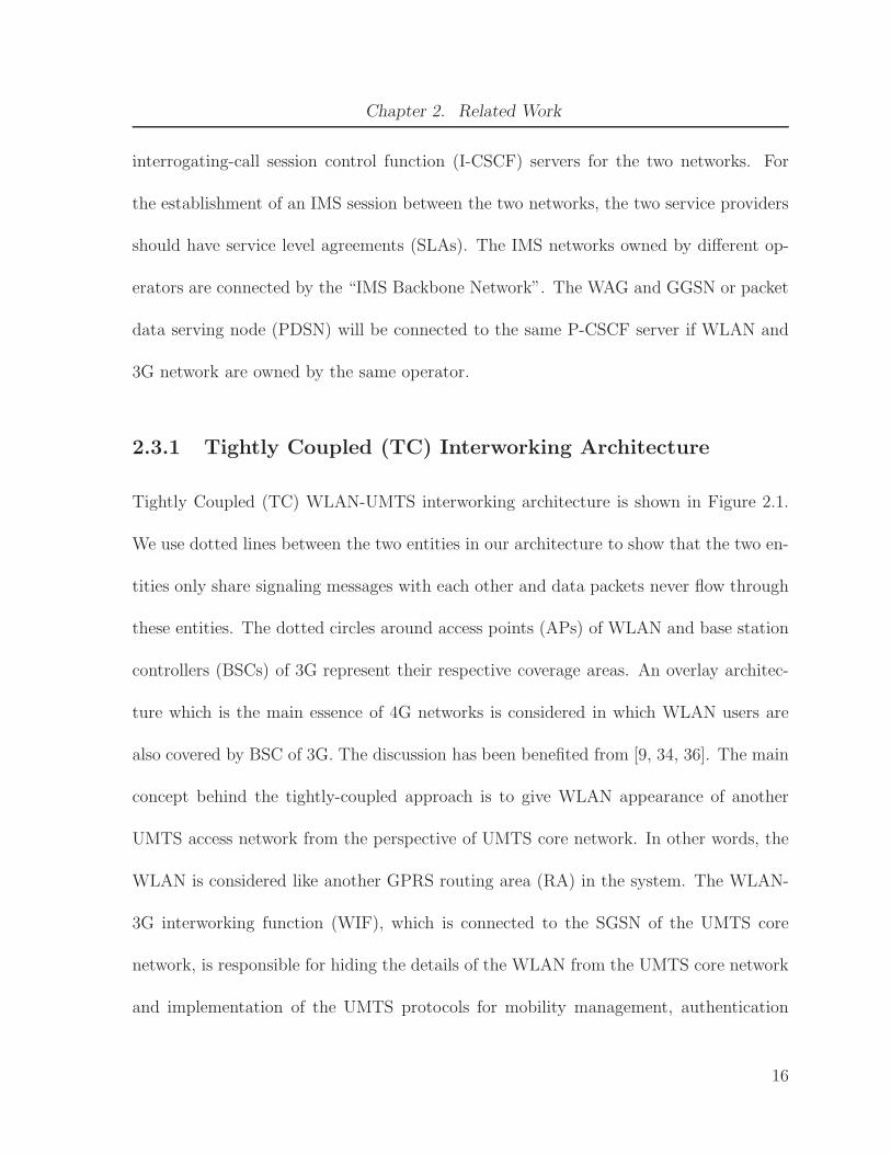
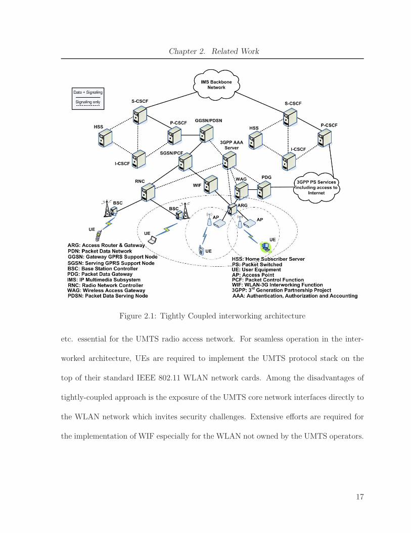
2.3.1 Tightly Coupled (TC) Interworking Architecture
Tightly Coupled (TC) WLAN-UMTS interworking architecture is shown in Figure 2.1.
We use dotted lines between the two entities in our architecture to show that the two en-
tities only share signaling messages with each other and data packets never flow through
these entities. The dotted circles around access points (APs) of WLAN and base station
controllers (BSCs) of 3G represent their respective coverage areas. An overlay architec-
ture which is the main essence of 4G networks is considered in which WLAN users are
also covered by BSC of 3G. The discussion has been benefited from [9, 34, 36]. The main
concept behind the tightly-coupled approach is to give WLAN appearance of another
UMTS access network from the perspective of UMTS core network. In other words, the
WLAN is considered like another GPRS routing area (RA) in the system. The WLAN-
3G interworking function (WIF), which is connected to the SGSN of the UMTS core
network, is responsible for hiding the details of the WLAN from the UMTS core network
and implementation of the UMTS protocols for mobility management, authentication
16
Chapter 2. Related Work
Figure 2.1: Tightly Coupled interworking architecture
etc. essential for the UMTS radio access network. For seamless operation in the inter-
worked architecture, UEs are required to implement the UMTS protocol stack on the
top of their standard IEEE 802.11 WLAN network cards. Among the disadvantages of
tightly-coupled approach is the exposure of the UMTS core network interfaces directly to
the WLAN network which invites security challenges. Extensive efforts are required for
the implementation of WIF especially for the WLAN not owned by the UMTS operators.
17

Chapter 2. Related Work
Figure 2.2: Loosely Coupled interworking architecture
2.3.2 Loosely Coupled (LC) Interworking Architecture
Loosely Coupled (LC) WLAN-UMTS interworking architecture is shown in Figure 2.2.
The discussion has been benefited from [34, 36]. In the loosely-coupled inter-working ar-
chitecture, the WLAN connects to the external packet data network (actually connects to
P-CSCF in case of IMS) and does not have any direct link to 3G network elements such as
SGSNs or GGSNs. Loosely-coupled architecture has distinct data paths for WLAN and
UMTS traffic. The inter-operability with 3G requires the support of Mobile-IP function-
18

Chapter 2. Related Work
alities or SIP protocol to handle mobility across networks and AAA services in the WAG
of WLAN. This support is necessary to interwork with the 3G’s home network AAA
servers. One of the major advantages of the loosely-coupled architecture is that it per-
mits independent deployment and traffic engineering of WLAN and 3G networks. Loose
coupling utilizes standard IETF-based protocols for AAA and mobility and therefore,
it does not necessitate the introduction of cellular technology into the WLAN network.
WLAN uses the EAP for authentication of the MN by supplying the subscriber iden-
tity, SIM-based authentication data, and encrypted session keys. In case when WLAN
is not owned by the 3G operator and SIM-based authentication is not feasible in the
WLAN system, standard user name and password procedures may be deployed. The
service continuity during handover to other access networks is not supported efficiently
in loose-coupling and causes significant handover latency and packet loss.
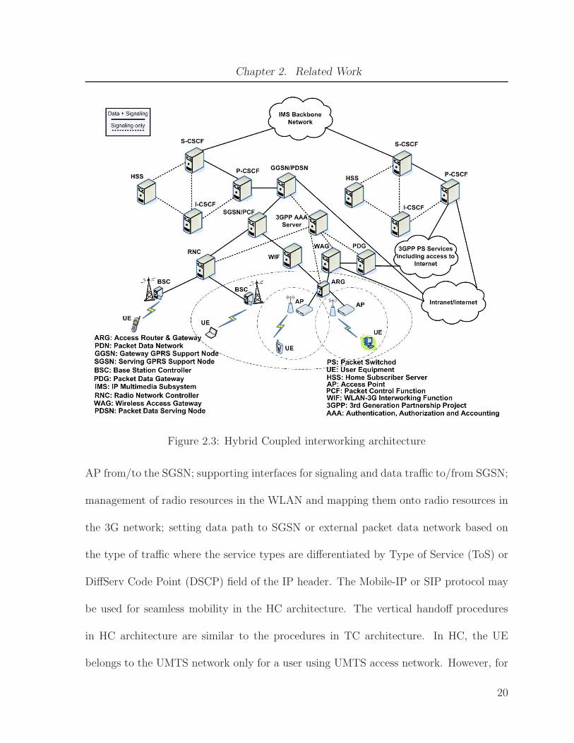
2.3.3 Hybrid Coupled (HC) Interworking Architecture
Hybrid Coupled (HC) WLAN-UMTS interworking architecture is shown in Figure 2.3.
The basic HC interworking architecture is proposed in [37]. The HC architecture distin-
guishes the data paths according to the type of traffic and is capable of accommodating
traffic from WLAN efficiently with guaranteed QoS and seamless mobility. The tightly-
coupled network architecture is chosen for real-time traffic and the loosely-coupled ar-
chitecture is selected for non-real time and bulky traffic. In HC architecture, the access
router and gateway (ARG) of WLAN is responsible for forwarding packets to/from an
19
Chapter 2. Related Work
Figure 2.3: Hybrid Coupled interworking architecture
AP from/to the SGSN; supporting interfaces for signaling and data traffic to/from SGSN;
management of radio resources in the WLAN and mapping them onto radio resources in
the 3G network; setting data path to SGSN or external packet data network based on
the type of traffic where the service types are differentiated by Type of Service (ToS) or
DiffServ Code Point (DSCP) field of the IP header. The Mobile-IP or SIP protocol may
be used for seamless mobility in the HC architecture. The vertical handoff procedures
in HC architecture are similar to the procedures in TC architecture. In HC, the UE
belongs to the UMTS network only for a user using UMTS access network. However, for
20
Chapter 2. Related Work
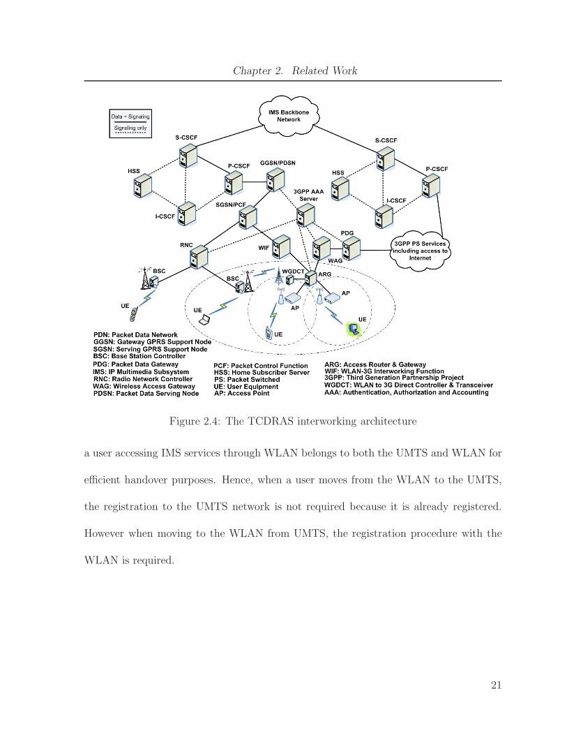
Figure 2.4: The TCDRAS interworking architecture
a user accessing IMS services through WLAN belongs to both the UMTS and WLAN for
efficient handover purposes. Hence, when a user moves from the WLAN to the UMTS,
the registration to the UMTS network is not required because it is already registered.
However when moving to the WLAN from UMTS, the registration procedure with the
WLAN is required.
21

Chapter 2. Related Work
2.3.4 The TCDRAS Interworking Architecture
Tightly Coupled with Direct Radio Access System (TCDRAS) WLAN-UMTS interwork-
ing architecture is shown in Figure 2.4. The basic TCDRAS architecture is proposed in
[38]. TCDRAS is based on the tight-coupling architecture but it also creates an addi-
tional wireless link between the base station of a UMTS cell and WLAN located within
the UMTS cell through WLAN to 3G Direct Controller and Transceiver (WGDCT). The
signaling in TCDRAS is still routed through the original TC path for network security
purposes. However, it provides the opportunity for dynamic distribution of data traffic
between the original TC path and the path available due to the added wireless link.
WGDCT uses IEEE 802.16 air interface and a WiMax transceiver for direct wireless link
established between WLAN and the UMTS base station overlaying the WLAN.
2.3.5 The LCDRAS Interworking Architecture
Loosely Coupled with Direct Radio Access System (LCDRAS) WLAN-UMTS interwork-
ing architecture is shown in Figure 2.5. The basic LCDRAS architecture is proposed in
[39]. LCDRAS is based on the loose-coupling architecture but it also creates an addi-
tional wireless link between the base station of a UMTS cell and WLAN located within
the UMTS cell through WGDCT. The IEEE 802.16 standard air interface is utilized in
LCDRAS to set up direct wireless link between the base station in UMTS cellular net-
works and local WLAN. The LCDRAS is capable of dynamically distributing signaling
and data traffic to reduce signaling cost and handoff latency via WGDCT.
22

Chapter 2. Related Work
Figure 2.5: The LCDRAS interworking architecture
23

Chapter 3
LCSCW2 and TCSCW2:
Architectures for IP Multimedia
Subsystem
In this chapter, we propose the LCSCW2 and TCSCW2 interworking architectures. The
LCSCW2 and TCSCW2 architectures integrate the satellite networks, 3G wireless net-
works, WiMax, and WLANs, and are based on the loosely coupling and tightly coupling
paradigm, respectively. They can support IMS sessions and provide global coverage. The
LCSCW2 architecture facilitates independent deployment and traffic engineering of var-
ious access networks. We also propose an analytical model to determine the associate
cost for the signaling and data traffic for inter-system communication in the LCSCW2
architecture. The analytical model can be easily extended to determine the associated
cost for the signaling and data traffic for inter-system communication in the TCSCW2
architecture as well. The cost analysis includes the transmission, processing, and queue-
ing costs at various entities. Numerical results are presented for different arrival rates
and session lengths.
24

Chapter 3. LCSCW2 and TCSCW2: Architectures for IP Multimedia Subsystem
Figure 3.1: The LCSCW2 interworking architecture.
3.1 The LCSCW2 Architecture
Our proposed LCSCW2 interworking architecture is depicted in Figure 3.1. This inter-
working architecture integrates satellite networks, 3G wireless cellular networks, WiMax,
and WLANs based on the loosely coupled approach. The areas covered by the SSBs,
3G base stations, WiMax base stations, and WLAN APs are shown by dotted lines in
Figure 3.1. Our proposed architecture is compatible with the IMS. Different ANs (e.g.,
3G networks, satellite networks, WiMax, and WLANs) can be owned by different ser-
vice providers (or the same operator). The wireless access gateways (WAGs) of WLAN,
WiMax, satellite and 3G networks are connected to different proxy-call session control
function (P-CSCF) servers in IMS via the Internet. In general, each AN has its own sepa-
25
Chapter 3. LCSCW2 and TCSCW2: Architectures for IP Multimedia Subsystem
rate WAG. In addition, there are separate serving-call session control function (S-CSCF)
and interrogating-call session control function (I-CSCF) servers for the two networks.
For the establishment of an IMS session between two access networks, the two service
providers should have a SLA with each other. IMS networks which are owned by differ-
ent operators are connected together through an IMS backbone network. The WAG and
packet data serving node (PDSN) are connected to the same P-CSCF server if WLAN,
WiMax, satellite and 3G network are owned by the same operator.
The mechanisms involved in the interworking architecture along with the function-
alities of various entities are explained below with reference to the 3GPP specification
[40]. Access to a locally connected IP network from a WLAN directly is called “WLAN
direct IP access”, which is provided by the loosely coupled architecture. The WAG is
a gateway via which the data to/from the satellite AN, WiMax AN, or WLAN AN can
be routed to/from an external IP network. In the LCSCW2 architecture, the satellite
AN comprises of satellites and satellite fixed earth station (SFES). Satellites convey data
and signaling messages between UE and SFES. The SFES performs power control, link
control, radio bearer control and paging functions. The SFES is connected to WAG for
accessing 3GPP packet switched (PS) and IMS services. The SFES determines whether
or not a given UE can receive the requested services based on the user subscription. The
SFES also determines the UE’s location via looking at the UE’s entry in the database
and its associated SSB ID. The UE’s database entry is created when the UE first regis-
ters with the satellite network and is updated when the UE moves from coverage area of
26

Chapter 3. LCSCW2 and TCSCW2: Architectures for IP Multimedia Subsystem
one SSB to another. The SFES sends a page request to the UE including its identifier.
During a pre-defined time, if the SFES gets the response from the UE, it then instructs
the UE to go through radio bearer (RB) establishment procedure. If the UE is unable
to respond to the page message within the pre-defined time, the SFES concludes that
the UE is unreachable [15]. The WiMax AN consists of WiMax base stations, which are
controlled by the WiMax base station controller (WBSC). Several WBSCs are controlled
by one WiMax network controller (WNC). The WNC is connected to WAG to provide
WiMax users with 3GPP PS and IMS services. The LCSCW2 interworking architecture
integrates satellite networks, 3G wireless networks, WiMax, and WLANs based on the
loose coupling approach since these ANs connect to the Internet or Intranet via WAG.
Then, through the Internet or Intranet, the UE can access CSCF servers of the IMS
network.
In the LCSCW2 architecture, the satellite network, WiMax and WLAN do not have
any direct link to 3G network elements such as serving GPRS support nodes (SGSNs) or
gateway GPRS support nodes (GGSNs). The LCSCW2 architecture has distinct signal-
ing and data paths for different ANs. The inter-operability with 3G requires the support
of mobile-IP functionalities and Session Initiation Protocol (SIP) to handle mobility
across networks, and authentication, authorization, and accounting (AAA) services in
the WAG of the AN. This support is necessary to interwork with the 3G’s home network
AAA servers. The authentication in the ANs is provided through the 3GPP system [40].
The main advantage of the LCSCW2 architecture is that it allows independent deploy-
27

Chapter 3. LCSCW2 and TCSCW2: Architectures for IP Multimedia Subsystem
ment and traffic engineering of satellite networks, WiMax, WLANs, and 3G networks.
In addition, this architecture utilizes standard IETF (Internet Engineering Task Force)
based protocols for AAA and mobility in the WiMax, WLANs, and satellite networks.
Our discussion and the cost analysis is equally valid whether the 3G technology be-
ing used is UMTS or CDMA2000 because there are corresponding network entities in
CDMA2000 for the entities in UMTS. Packet data serving node (PDSN) in CDMA2000
performs the same functions as GGSN in UMTS. Packet control function (PCF) in
CDMA2000 performs the same function as SGSN in UMTS. PCF connects to the PDSN
in CDMA2000 as SGSN connects to GGSN in UMTS.
3.2 The TCSCW2 Architecture
Our proposed TCSCW2 interworking architecture is depicted in Figure 3.2. This inter-
working architecture integrates satellite networks, 3G wireless cellular networks, WiMax,
and WLANs based on the loosely coupled approach. The areas covered by the satellite
spot beams SSBs, 3G base stations, WiMax base stations, and WLAN access points APs
are shown by dotted lines in Figure 3.2. Our proposed architecture is compatible with the
IMS. Different ANs (e.g., 3G networks, satellite networks, WiMax, and WLANs) can be
owned by different service providers (or the same operator). The packet data gateways
(PDGs) of WLAN, WiMax, satellite and 3G networks are connected to different P-CSCF
servers in IMS. In general, each AN has its own separate WAG. In addition, there are
separate S-CSCF and I-CSCF servers for the two networks. For the establishment of an
28
Chapter 3. LCSCW2 and TCSCW2: Architectures for IP Multimedia Subsystem
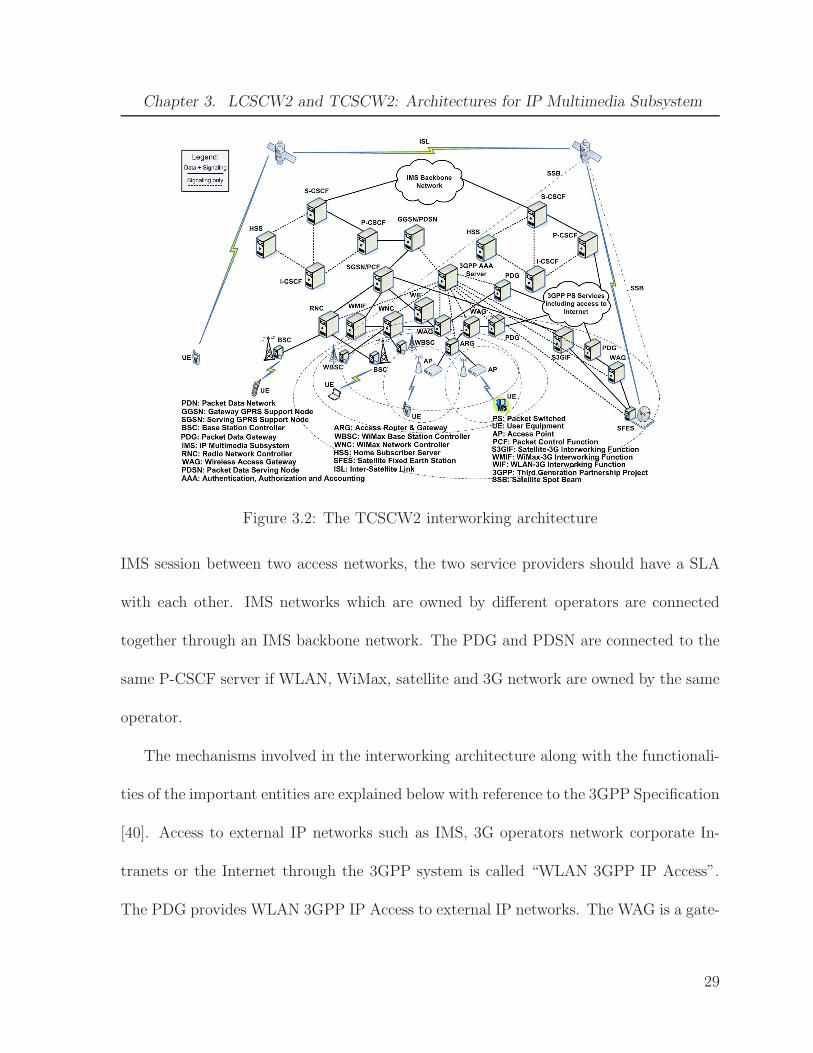
Figure 3.2: The TCSCW2 interworking architecture
IMS session between two access networks, the two service providers should have a SLA
with each other. IMS networks which are owned by different operators are connected
together through an IMS backbone network. The PDG and PDSN are connected to the
same P-CSCF server if WLAN, WiMax, satellite and 3G network are owned by the same
operator.
The mechanisms involved in the interworking architecture along with the functionali-
ties of the important entities are explained below with reference to the 3GPP Specification
[40]. Access to external IP networks such as IMS, 3G operators network corporate In-
tranets or the Internet through the 3GPP system is called “WLAN 3GPP IP Access”.
The PDG provides WLAN 3GPP IP Access to external IP networks. The WAG is a gate-
29

Chapter 3. LCSCW2 and TCSCW2: Architectures for IP Multimedia Subsystem
way via which the data to/from the satellite AN, WiMax AN, or WLAN AN is routed
to/from the external IP network. In the TCSCW2 architecture, a UE is identified by
multiple IP addresses. For example, in case of a UE in WLAN accessing IMS or 3GPP
PS services, the UE is identified by two IP addresses i.e. a local IP address and a remote
IP address. A local IP address is used to deliver a packet to the UE in WLAN AN.
The local IP address identifies the UE in WLAN AN. The UE’s local IP address may
be translated by network address translation (NAT) before delivering the packet from
UE to other IP network including public land mobile network (PLMN). The remote IP
address is used by the data packet encapsulated inside the UE to PDG tunnel. The
remote IP address identifies the UE in the network which the WLAN is accessing via
PDG. A tunnel is established from the UE to PDG for carrying PS based services traffic
in 3GPP IP Access. The data for more than one IP flow and for different services may be
carried in one tunnel. It may not be possible to separate individual IP flows and service
traffic at intermediate nodes because of the possible encryption of the data including IP
header within these tunnels. However, QoS can be assured if the WLAN UE and PDG
deploy DiffServ mechanism and appropriately color the differentiated services (DS) field
in the external IP header according to the QoS requirement of a particular traffic flow.
The PDG assigns remote IP address to the WLAN UE. It registers the WLAN UE’s
local IP address and binds the UE local IP address with the UE remote IP address. The
PDG also performs the encapsulation and decapsulation of packets since it is the termi-
nating/originating point of tunnel between UE and PDG. The WAG performs collection
30

Chapter 3. LCSCW2 and TCSCW2: Architectures for IP Multimedia Subsystem
of per tunnel accounting information e.g. byte count, elapsed time etc. and sends this
charging information to the 3GPP AAA server [40].
In the TCSCW2 architecture, the WLAN-3G interworking function (WIF), which is
connected to the SGSN or PCF of the 3G core network, is responsible for hiding the
details of the WLAN from the 3G core network and implementation of the 3G protocols
for mobility management, authentication etc. essential for the 3G radio access network.
The WIF gives WLAN appearance of another 3G AN from the perspective of 3G core
network. In other words, the WLAN is considered like another GPRS Routing Area
(RA) in the system. In the TCSCW2 architecture, the satellite access network comprises
of satellites and SFES. Satellites convey data and signaling messages exchanged between
UE and SFES. SFES performs the power control, link control, radio bearer control and
paging functions. Satellites can be interconnected in an orbit via ISL. SFES is connected
to WAG for accessing 3GPP PS and IMS services via PDG. Satellite-3G interworking
function (S3GIF) is mainly responsible for connecting satellite systems with core 3G
network. The S3GIF, which is connected to the SGSN/PCF of the UMTS/CDMA2000
core network, is responsible for hiding the details of the satellite network from the 3G
core network. It is also responsible for the conversion of signaling and packet formats
of satellite network to UMTS/CDMA2000 network and vice versa. The WiMax AN
consists of WiMax base stations controlled by the WBSC. Many WBSCs are controlled
by one WNC. The WNC is connected to WAG to provide WiMax users with 3GPP
PS and IMS services via PDG. The WiMax-3G interworking function (WMIF) connects
31
Chapter 3. LCSCW2 and TCSCW2: Architectures for IP Multimedia Subsystem
the WNC to the core 3G network. The TCSCW2 interworking architecture integrate
satellite network, 3G, WiMax, and WLAN based on the tight coupling approach since
the satellite network, 3G, WiMax, and WLAN are directly coupled to the 3G network
via interworking functions.
For seamless operation in the TCSCW2 architecture, UEs are required to implement
the 3G protocol stack on the top of their standard network cards. Among the disadvan-
tages of tightly-coupled approach is exposure of the 3G core network interfaces directly
to the WLAN, WiMax and satellite network which invites security challenges. Extensive
efforts are required for the implementation of interworking functions especially for the
ANs not owned by the 3G operators. The 3G core network entities i.e. SGSN and GGSN
need to be modified to handle the increased load caused by the direct injection of the
traffic from other ANs. The TCSCW2 mandates the use of 3G-specific authentication
mechanisms based on universal subscriber identity module (USIM) or removable-user
identity module (R-UIM) cards for authentication in other ANs. This requires ANs to
interconnect to the 3G carriers’ signaling system number 7 (SS7) network for perform-
ing authentication procedures. Hence either other ANs interface cards, for e.g., IEEE
802.11 WLAN network interface card, be equipped with built-in USIM or R-UIM slots
or external USIM or R-UIM cards need to be plugged separately into the UEs. Among
the advantages of the TCSCW2 architecture is the possibility of reuse of AAA, mobility
management and QoS handling infrastructures of 3G cellular networks. The TCSCW2
architecture enables the provision of 3G services to other ANs users with guaranteed QoS
32

Chapter 3. LCSCW2 and TCSCW2: Architectures for IP Multimedia Subsystem
and seamless mobility. However, the 3G core network nodes can not accommodate the
bulky data traffic from the other ANs during busy hours since the core network nodes
are designed to support the small-sized data of circuit voice calls or short packets.
3.3 An Analytical Model for Cost Analysis
We use the inter-system communication cost analysis to evaluate the performance of our
proposed LCSCW2 interworking architecture. The total inter-system communication
cost Cs is given by:
Cs = Ct + Cp + Cq (3.1)
where Ct, Cp, and Cq denote the transmission cost, processing cost, and queueing cost,
respectively. The transmission cost Ct is the cost incurred due to the transmission of
signaling and/or data. It depends on the packet arrival rate, the transmission rate of
the link, and the distance between the neighboring network entities. The processing cost
Cp is the cost associated with the encapsulation, decapsulation and routing of packets.
The queueing cost Cq is the cost incurred due to the queuing of packets in each network
entity. Our analysis is applicable to both IPv4 and IPv6 packet types. Also, our analysis
is valid for both UMTS and CDMA2000 3G networks.
In the LCSCW2 architecture, communication paths are different when the source node
(SN) resides in either WiMax, WLAN or satellite network. In the following analysis, we
assume that SN is communicating via a WLAN and the correspondent node (CN) is
using a 3G wireless cellular network. However, the analysis can easily be extended for
33
Chapter 3. LCSCW2 and TCSCW2: Architectures for IP Multimedia Subsystem
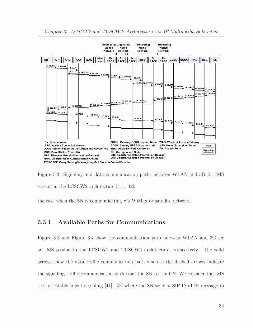
Figure 3.3: Signaling and data communication paths between WLAN and 3G for IMS
session in the LCSCW2 architecture [41], [42].
the case when the SN is communicating via WiMax or satellite network.
3.3.1 Available Paths for Communications
Figure 3.3 and Figure 3.4 show the communication path between WLAN and 3G for
an IMS session in the LCSCW2 and TCSCW2 architecture, respectively. The solid
arrows show the data traffic communication path whereas the dashed arrows indicate
the signaling traffic communication path from the SN to the CN. We consider the IMS
session establishment signaling [41], [42] where the SN sends a SIP INVITE message to
34
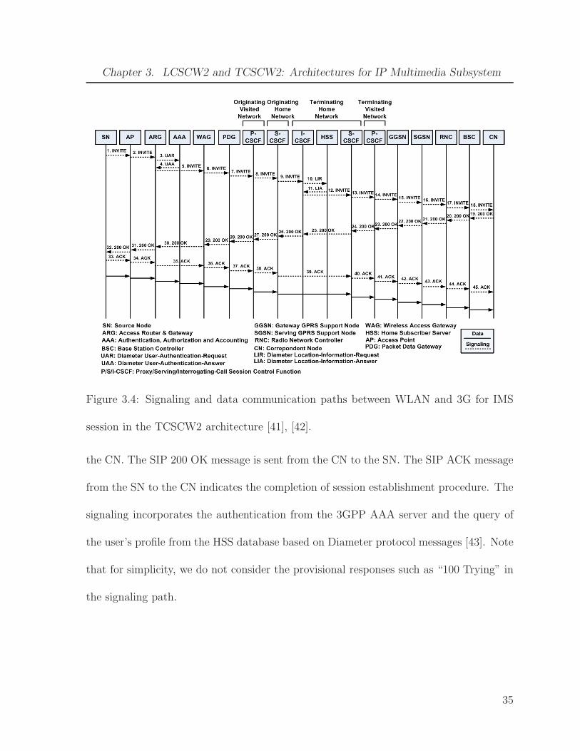
Chapter 3. LCSCW2 and TCSCW2: Architectures for IP Multimedia Subsystem
Figure 3.4: Signaling and data communication paths between WLAN and 3G for IMS
session in the TCSCW2 architecture [41], [42].
the CN. The SIP 200 OK message is sent from the CN to the SN. The SIP ACK message
from the SN to the CN indicates the completion of session establishment procedure. The
signaling incorporates the authentication from the 3GPP AAA server and the query of
the user’s profile from the HSS database based on Diameter protocol messages [43]. Note
that for simplicity, we do not consider the provisional responses such as “100 Trying” in
the signaling path.
35

Chapter 3. LCSCW2 and TCSCW2: Architectures for IP Multimedia Subsystem
3.3.2 Transmission Cost
Let λ denote the IMS session arrival rate (requests per second) and ℓ denote the number
of packets per request both for signaling and data from a SN. For transmission and
processing cost calculation of IMS signaling traffic, ℓ is equal to 1 because we assume
that one signaling packet can carry one particular signaling message such as 200 OK from
one node to its adjacent node. We take into account the traffic coming from other users in
the same AN as well as from other ANs by considering background utilization at network
entities. The transmission cost between WLAN and 3G wireless cellular networks for
IMS signaling traffic Csigt is:
Csigt = λℓ(2ϕ+ ψ(3dap−arg + 2darg−aaa + 3darg−wag + 3dwag−inet + 3dinet−pcscf
+ 6dpcscf−scscf + 4dscscf−icscf + dscscf−scscf + 2dicscf−hss + 3dpcscf−ggsn
+ 3dsgsn−ggsn + 3dsgsn−rnc + drnc−bsc)) (3.2)
where ϕ and ψ are the unit packet transmission costs in wireless and wired link respec-
tively; dap−arg, darg−aaa, darg−wag, dwag−inet, dinet−pcscf , dpcscf−scscf , dscscf−icscf , dscscf−scscf ,
dicscf−hss, dpcscf−ggsn, dsgsn−ggsn, dsgsn−rnc, and drnc−bsc denote the distance between AP
and ARG, ARG and AAA, ARG and WAG, WAG and Internet, Internet and P-CSCF,
P-CSCF and S-CSCF, S-CSCF and I-CSCF, S-CSCF server of the SN IMS network and
the S-CSCF server of the CN IMS network, I-CSCF and HSS, P-CSCF and GGSN, SGSN
and GGSN, SGSN and RNC, and RNC and BSC, respectively. The distance is defined
as the number of hops that a packet has traveled [20].
36

Chapter 3. LCSCW2 and TCSCW2: Architectures for IP Multimedia Subsystem
The transmission cost between WLAN and 3G wireless cellular networks for IMS data
traffic Cdatat is:
Cdatat = λℓ(2ϕ+ ψ(dap−arg + darg−wag + dwag−inet + dinet−pcscf + 2dpcscf−scscf
+ dscscf−scscf + dpcscf−ggsn + dggsn−sgsn + dsgsn−rnc + drnc−bsc)) (3.3)
By following the same methodology, we can calculate the transmission cost for commu-
nication paths between WiMax and 3G, as well as satellite and 3G for IMS traffic.
3.3.3 Processing Cost
For processing cost calculation, we first assume that Nbsc BSCs are connected to each
RNC, Nrnc RNCs are connected to each SGSN, Nsgsn SGSNs are connected to each
GGSN, Nggsn GGSNs and Npcscf P-CSCFs are connected to the Internet. In addition,
let Nmn1, Nmn2, Nmn3, and Nmn4 denote the number of users in the coverage area of 3G
wireless cellular network, WLAN, WiMax, and SSB of the satellite network, respectively.
The total number of users N in the network can be given as:
N = Nmn1 +Nmn2 +Nmn3 +Nmn4 (3.4)
The processing cost between WLAN and 3G wireless cellular network for IMS signaling
traffic Csigp is:
Csigp = 3Cp−ap + 4Cp−arg + Cp−aaa + 3Cp−wag + 3Cp−inet + 6Cp−pcscf + 6Cp−scscf
+ 3Cp−icscf + Cp−hss + 3Cp−ggsn + 3Cp−sgsn + 3Cp−rnc + 3Cp−bsc (3.5)
37
Chapter 3. LCSCW2 and TCSCW2: Architectures for IP Multimedia Subsystem
where Cp−ap represents the processing cost at AP and is given as:
Cp−ap = λℓγap (3.6)
where γap denotes the unit packet processing cost at AP. The unit packet processing
cost includes the cost for encapsulation and decapsulation of packets. Similarly, Cp−arg,
Cp−wag, Cp−pcscf , Cp−scscf , and Cp−icscf represent the processing costs at ARG, WAG, P-
CSCF, S-CSCF and I-CSCF, respectively. Their expressions are similar to that of Cp−ap
with the only difference that they have their own respective unit packet processing costs.
Cp−aaa represents the processing cost at the AAA server and is given by:
Cp−aaa = λℓ
(
γaaa + ω1
(
logk+1N +L
S
))
(3.7)
where γaaa denotes the unit packet processing cost at AAA server. We assume that IP
addresses are searched in the lookup table using the multiway and multicolumn search
[44]. We also assume that the number of entries in the lookup tables for AAA server
and HSS are equal to the total number of users N in the network because 3GPP AAA
server based authentication and subscription database HSS are used [40]. In addition,
L is the IP address length in bits (e.g. L is 32 for IPv4 and 128 for IPv6), S is the
machine word size in bits, and k is a system-dependent constant. In our analysis, ωi
where i ∈ {1, 2, 3, 4} denotes the weighting factors. Cp−hss represents the processing
cost at HSS and its expression is similar to that of Cp−aaa with the only difference that
it has its own specific unit packet processing cost. Cp−ggsn, Cp−sgsn, Cp−rnc, and Cp−bsc
represents the processing costs at GGSN, SGSN, RNC, and BSC respectively with similar
38

Chapter 3. LCSCW2 and TCSCW2: Architectures for IP Multimedia Subsystem
expressions as that of Cp−aaa with the difference that they have their own respective unit
packet processing costs. Also, the logarithm is taken for Nsgsn in case of Cp−ggsn, Nrnc
in case of Cp−sgsn, Nbsc in case of Cp−rnc, and Nmn1 in case of Cp−bsc instead of N in the
expression of Cp−aaa. Cp−inet represents the processing cost at the Internet and is given
as:
Cp−inet = λℓ
(
γinet + ω2
(
logk+1(Ngp) +L
S
))
(3.8)
where γinet denotes the unit packet processing cost at the Internet, Ngp = Nggsn +Npcscf ,
and ℓ is equal to 1 for IMS signaling processing cost calculation.
The processing cost between WLAN and 3G wireless cellular network for IMS data
traffic Cdatap is:
Cdatap = Cp−ap + Cp−arg + Cp−wag + Cp−inet + 2Cp−pcscf + 2Cp−scscf + Cp−ggsn
+ Cp−sgsn + Cp−rnc + Cp−bsc (3.9)
Following the same approach, we can calculate the processing cost for communication
paths between WiMax and 3G, as well as satellite and 3G for IMS traffic.
3.3.4 Queueing Cost
For the queueing cost calculation, we first model the communication path between SN
and CN as a network of M/M/1 queues [45], [46]. The queueing cost is proportional to
the total number of packets in the queueing network. The queueing cost between WLAN
39

Chapter 3. LCSCW2 and TCSCW2: Architectures for IP Multimedia Subsystem
and 3G wireless cellular network for IMS signaling traffic Csigq is:
Csigq = ω3(3E[nap] + 4E[narg] + E[naaa] + 3E[nwag] + 3E[ninet] + 6E[npcscf ]
+ 6E[nscscf ] + 3E[nicscf ] + E[nhss] + 3E[nggsn] + 3E[nsgsn] + 3E[nrnc]
+ 3E[nbsc]) (3.10)
where E[nap], E[narg], E[naaa], E[nwag], E[ninet], E[npcscf ], E[nscscf ] E[nicscf ], E[nhss],
E[nggsn], E[nsgsn], E[nrnc], E[nbsc] denote the expected number of packets in the queue of
AP, ARG, AAA, WAG, Internet, P-CSCF, S-CSCF, I-CSCF, HSS, GGSN, SGSN, RNC,
and BSC, respectively. The value of E[nap] is equal to:
E[nap] =ρap
1 − ρap(3.11)
where ρap = λe−ap/µap represents the utilization at AP queue, µap denotes the service
rate at AP queue and λe−ap represents the effective arrival rate (in packets per second)
at AP queue. That is, λe−ap =∑
i∈Napλi, where Nap denotes the number of active users
in the AP coverage area that are engaged in communication with the AP, and hence
Nap ⊆ Nmn2. The effective arrival rate λe at a network node can be determined from
the utilization at that node. Similarly, the λe at queues of other network nodes can be
calculated and expressions can be determined for the expected number of packets at other
network entities.
The queueing cost between WLAN and 3G wireless cellular network for IMS data
40

Chapter 3. LCSCW2 and TCSCW2: Architectures for IP Multimedia Subsystem
traffic Cdataq is:
Cdataq = ω4(E[nap] + E[narg] + E[nwag] + E[ninet] + 2E[npcscf ] + 2E[nscscf ]
+ E[nggsn] + E[nsgsn] + E[nrnc] + E[nbsc]) (3.12)
Following the same approach, we can calculate the queueing cost for communication
paths between WiMax and 3G, as well as satellite and 3G for IMS traffic.
3.4 Numerical Results
In this section, we present the numerical results for the cost analysis of our proposed
LCSCW2 and TCSCW2 interworking architectures. The total system signaling and data
costs for IMS traffic are determined for the case when the SN is using the WLAN and
the CN is in 3G wireless cellular network.
We consider a network containing two 3G BSCs, three WiMax BSCs, 12 WLANs,
and one SSB. The cell radius for 3G BSC, WiMax BSC, and WLAN is taken to be 1000
m, 700 m, and 50 m, respectively. Their user densities are taken to be 0.001, 0.001, and
0.008 per square meter, respectively [39], [38], [47]. The SSB is assumed to cover an
area of 20 square kilometer and user density in its coverage area is taken to be 0.0005 per
square meter [12]. The number of users resulting from the selection of these cell radii and
user densities in different ANs are: Nmn1 = 5000, Nmn2 = 600, Nmn3 = 3000, and Nmn4
= 10000. In our network setting, two GGSNs and two P-CSCF servers are connected to
the Internet; each GGSN supports three SGSNs; each SGSN supports four RNCS, and
41

Chapter 3. LCSCW2 and TCSCW2: Architectures for IP Multimedia Subsystem
each RNC controls five BSCs. The IP address length L and processor machine word size
S are taken to be 32 bits. The system dependent constant value k is equal to 5 [44]. The
wired hop distances, dpcscf−ggsn and dsgsn−rnc, which involve the core 3G network entities
are equal to 4, and rest of the distances are equal to 2 [39], [38], [21]. The trunked Pareto
distribution is assumed for packet length with average packet length equal to 480 bytes.
The inter-arrival time for packets is exponentially distributed [35].
The weighting factors, ω1 and ω2, corresponding to the table lookup processing cost
are taken equal to 1 × 10⁻⁶ as lookup delay is increased by 100 ns for each memory
access [44]. The weighting factors, ω3 and ω4, corresponding to queueing cost are equal
to each other and are chosen such that sum of all the weighting factors is equal to 1 (i.e.
∑
i ωi = 1). We consider wireless link channels to be 9.6 kbps, 19.2 kbps or 19.2 kbps
and the wired links to be 1 Gbps. The unit transmission costs for the wired link ψ and
the wireless link ϕ are equal to 3.84 × 10⁻⁶ and 0.1, respectively [48], [49] so that the
unit transmission costs can be interpreted as typical wireless and wired link delays in
seconds. The service rate µ at all the network entities is taken equal to 250 packets/sec.
The unit packet processing cost for all the network entities is taken equal to 4 × 10⁻³
except the core 3G network entities i.e. SGSN and GGSN and the Internet for which
the unit packet processing cost is taken twice as compared to other network entities in
accordance with [39], [38].
For IMS data traffic, we consider audio and video sessions using different codecs which
give different packet generation rates. For instance, GSM voice encoder at 13 kbps, G.726
42
Chapter 3. LCSCW2 and TCSCW2: Architectures for IP Multimedia Subsystem
4 9 150
5
10
15
20
25
30
35
IMS Signaling Arrival Rate λ (packets per second)
Sys
tem
Sig
nalin
g C
ost
Ct
Cp
Cq
Cs
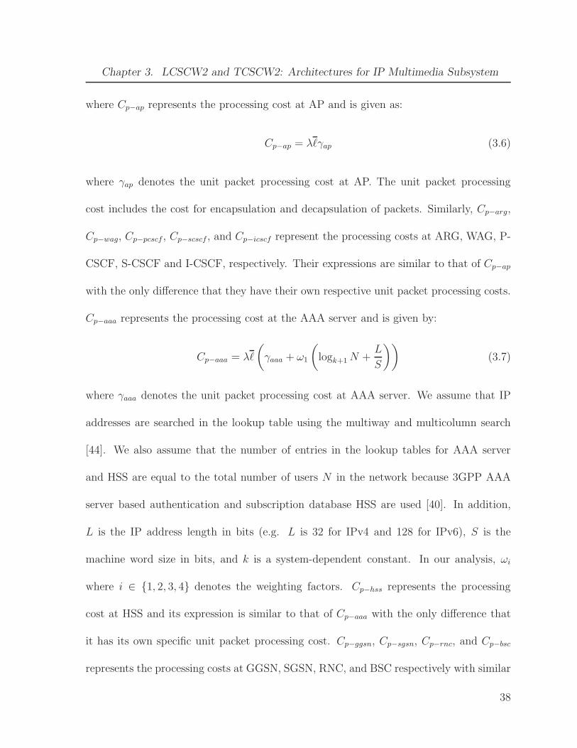
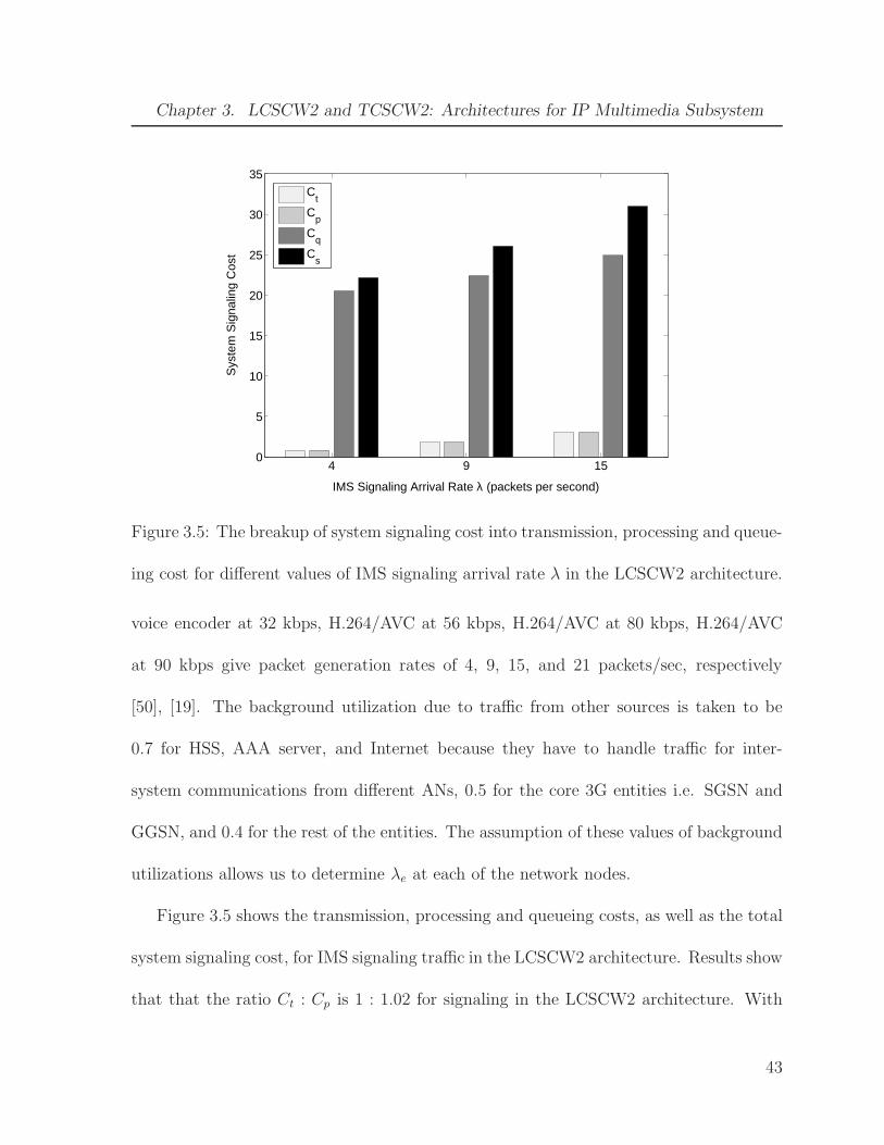
Figure 3.5: The breakup of system signaling cost into transmission, processing and queue-
ing cost for different values of IMS signaling arrival rate λ in the LCSCW2 architecture.
voice encoder at 32 kbps, H.264/AVC at 56 kbps, H.264/AVC at 80 kbps, H.264/AVC
at 90 kbps give packet generation rates of 4, 9, 15, and 21 packets/sec, respectively
[50], [19]. The background utilization due to traffic from other sources is taken to be
0.7 for HSS, AAA server, and Internet because they have to handle traffic for inter-
system communications from different ANs, 0.5 for the core 3G entities i.e. SGSN and
GGSN, and 0.4 for the rest of the entities. The assumption of these values of background
utilizations allows us to determine λe at each of the network nodes.
Figure 3.5 shows the transmission, processing and queueing costs, as well as the total
system signaling cost, for IMS signaling traffic in the LCSCW2 architecture. Results show
that that the ratio Ct : Cp is 1 : 1.02 for signaling in the LCSCW2 architecture. With
43

Chapter 3. LCSCW2 and TCSCW2: Architectures for IP Multimedia Subsystem
4 9 150
5
10
15
20
25
30
IMS Signaling Arrival Rate λ (packets per second)
Sys
tem
Sig
nalin
g C
ost
Ct
Cp
Cq
Cs
Figure 3.6: The breakup of system signaling cost into transmission, processing and queue-
ing cost for different values of IMS signaling arrival rate λ in the TCSCW2 architecture.
our selection of parameters, queueing cost is higher than the transmission and processing
costs for signaling and lower than the transmission and processing costs for data.
Figure 3.6 shows the transmission, processing and queueing costs, as well as the total
system signaling cost, for IMS signaling traffic in the TCSCW2 architecture. Results
show that that the ratio Ct : Cp is 1 : 0.959 for signaling in the TCSCW2 architecture.
With our selection of parameters, queueing cost is higher than the transmission and
processing costs for signaling and lower than the transmission and processing costs for
data.
Figure 3.7 shows the effect of varying IMS signaling arrival rate λ on total system
signaling cost in the LCSCW2 and TCSCW2 architectures. It can be observed that
44

Chapter 3. LCSCW2 and TCSCW2: Architectures for IP Multimedia Subsystem
0 5 10 15 20 2515
20
25
30
35
40
IMS Signaling Arrival Rate λ (packets per second)
Sys
tem
Sig
nalin
g C
ost
LCSCW2TCSCW2
Figure 3.7: Effect of varying the IMS signaling arrival rate λ on the total system signaling
cost between WLAN and 3G in the LCSCW2 and TCSCW2 architectures.
the system signaling cost increases almost linearly with the increasing value of λ in
both the architectures. A comparison of the system signaling cost in the LCSCW2 and
TCSCW2 architectures reveals that the signaling cost in the TCSCW2 architecture is
always considerably less than the LCSCW2 architecture for all values of λ. A reduction
in the system signaling cost is an important achievement of the TCSCW2 architecture
which justifies the deployment of PDGs. It is to be noted that signaling cost is most
critical in the networks because session establishment, session resource reservation, UE
registration, and vertical handoffs are achieved via the signaling. Hence, QoS can be
guaranteed to an extent in the TCSCW2 architecture. In the TCSCW2 architecture,
each AN has its own PDG via which the traffic is routed to IMS network without passing
45
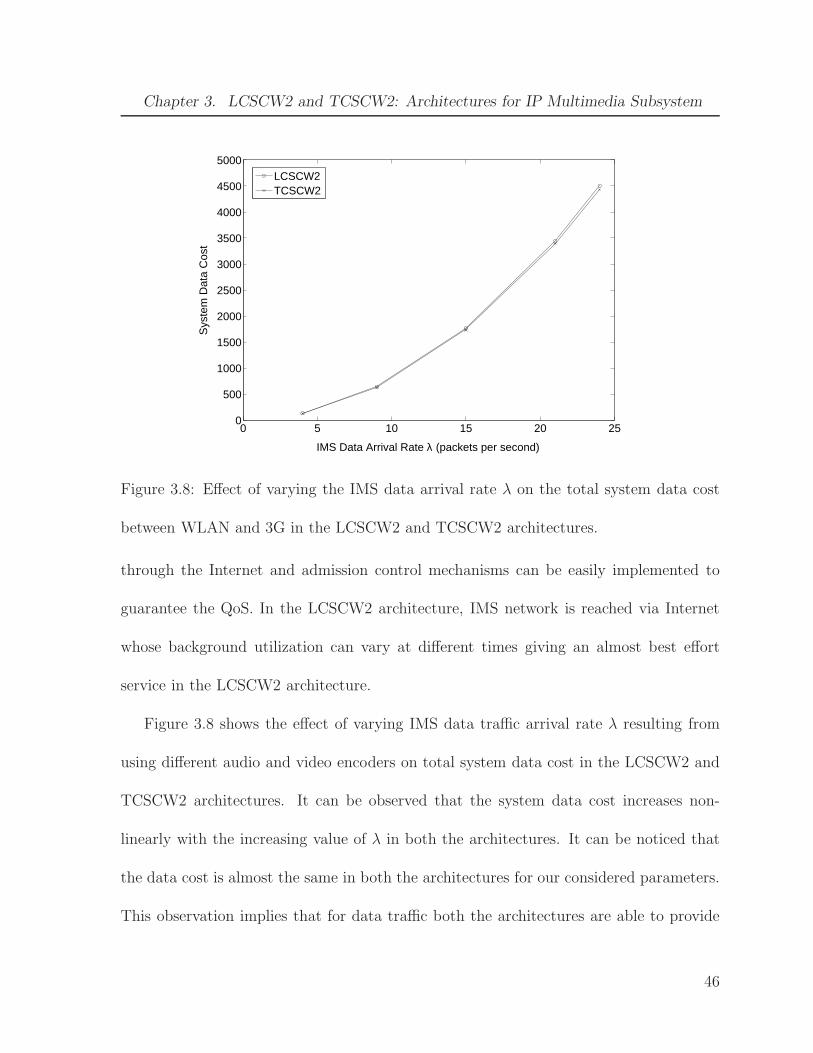
Chapter 3. LCSCW2 and TCSCW2: Architectures for IP Multimedia Subsystem
0 5 10 15 20 250
500
1000
1500
2000
2500
3000
3500
4000
4500
5000
IMS Data Arrival Rate λ (packets per second)
Sys
tem
Dat
a C
ost
LCSCW2TCSCW2
Figure 3.8: Effect of varying the IMS data arrival rate λ on the total system data cost
between WLAN and 3G in the LCSCW2 and TCSCW2 architectures.
through the Internet and admission control mechanisms can be easily implemented to
guarantee the QoS. In the LCSCW2 architecture, IMS network is reached via Internet
whose background utilization can vary at different times giving an almost best effort
service in the LCSCW2 architecture.
Figure 3.8 shows the effect of varying IMS data traffic arrival rate λ resulting from
using different audio and video encoders on total system data cost in the LCSCW2 and
TCSCW2 architectures. It can be observed that the system data cost increases non-
linearly with the increasing value of λ in both the architectures. It can be noticed that
the data cost is almost the same in both the architectures for our considered parameters.
This observation implies that for data traffic both the architectures are able to provide
46

Chapter 3. LCSCW2 and TCSCW2: Architectures for IP Multimedia Subsystem
0 50 100 150 200 250 300 350 400 450 5000
1
2
3
4
5
6x 10
4
IMS Data Session Duration (seconds)
Sys
tem
Dat
a C
ost
LCSCW2TCSCW2
Figure 3.9: Effect of varying the average IMS session duration ℓ on the total system data
cost between WLAN and 3G in the LCSCW2 and TCSCW2 architectures.
similar kind of service. The linear increase of system signaling cost and non-linear increase
of system data cost with λ is dependent on the ratios of transmission, processing and
queueing costs in the total system cost.
Figure 3.9 shows the effect of varying IMS session duration on total system data cost
in the LCSCW2 and TCSCW2 architectures. The arrival rate λ is assumed to be to
21 packets/sec. The IMS data session is run for 30, 60, 120, 240, and 480 seconds with
the corresponding values of ℓ as 315, 630, 1260, 2520, 5040, and 10080, respectively.
Results show that the system data cost increases almost linearly with increasing session
length for both the architectures and the system data cost is almost the same in the two
architectures.
47

Chapter 3. LCSCW2 and TCSCW2: Architectures for IP Multimedia Subsystem
Experiments were conducted for the non-IMS traffic as well. It was observed from
those experiments that the TCSCW2 architecture provides significant improvement over
the LCSCW2 architecture for the non-IMS traffic. Hence, the deployment of interworking
functions is justified for the non-IMS traffic. For IMS session, traffic is routed to the 3G
core network through IMS CSCF servers and interworking functions in the TCSCW2
architecture do not play any role in the routing of signaling and data traffic directly into
the 3G core network from an AN.
3.5 Summary
In this chapter, we proposed the LCSCW2 and TCSCW2 interworking architectures for
4G heterogeneous wireless networks. The LCSCW2 and TCSCW2 architectures inte-
grates the satellite networks, 3G wireless networks, WiMax, and WLANs. The LCSCW2
architecture supports IMS sessions, provides global coverage, and facilitates independent
deployment of various access networks. We also proposed a cost model to determine the
associate cost for the IMS signaling and data traffic in the LCSCW2 architecture. We
presented the numerical results for the system cost, as well as the transmission, process-
ing, and queueing costs under different arrival rates and session lengths for LCSCW2 and
TCSCW2 architectures.
48
Chapter 4
Analysis of SIP-based Signaling for
IMS Sessions in 4G Networks
In this chapter, we study the SIP-based IMS signaling delay for registration, session
establishment and session re-establishment for different 3G and WLAN channel rates.
The SN and the CN needs to register themselves with the IMS network before an IMS
session can be established between them. When the UE (SN or CN) moves to a new
network during an IMS session referred to as “mid-session mobility”, the terminal needs
to inform the other node by sending a re-INVITE message about the terminals’ new
IP address and to update the session description. However, during the “mid-session
mobility”, before a terminal can send a re-INVITE message to the other node, a terminal
requires to perform some procedures for attaching itself to the new AN infrastructure. For
instance, a terminal attaches to 3G UMTS network using GPRS attach and PDP context
activation procedure. A terminal uses DHCP registration procedure for connecting to the
AN of WLAN. We calculate the delay for IMS session re-establishment after undergoing
a vertical handoff for different scenarios.
49

Chapter 4. Analysis of SIP-based Signaling for IMS Sessions in 4G Networks
4.1 Delay Analysis of IMS Signaling Procedures
In this section, we analyze the delay for the IMS signaling procedures. The delay consists
of three parts, i.e., transmission delay, processing delay, and queueing delay.
Dtotal = Dtrans +Dproc +Dqueue (4.1)
where Dtotal denotes the total delay for a signaling procedure, Dtrans denotes the trans-
mission delay, Dproc denotes the processing delay and Dqueue denotes the queueing delay.
The transmission delay considered here includes the propagation delay as well. The trans-
mission delay is the delay incurred due to the transmission of signaling which depends
on the message sizes as well as the rate or the bandwidth of the channel and the delay
incurred due to the propagation of signaling messages from one node to another which
depends on the distance between the nodes. Processing delay is the delay associated with
the encapsulation, decapsulation and routing of packets. Queueing delay is the delay in-
curred due to the queuing of packets in the queues at each node. Our analysis is equally
valid for IPv4 as well as IPv6. Depending on the ANs in 4G wireless networks, there will
be different entities in the path between SN or CN and the P-CSCF server of the IMS.
Hence transmission, processing and queuing delays of the intervening components will be
added to the total delay. For instance, if the SN is in 3G UMTS network, then the path
between SN and the P-CSCF server is given as:
SN → BSC → RNC → SGSN → GGSN → P − CSCF (4.2)
50

Chapter 4. Analysis of SIP-based Signaling for IMS Sessions in 4G Networks
If the SN is in WLAN, then the path between SN and the P-CSCF server is given as:
SN → AP → ARG→WAG→ P − CSCF (4.3)
For the GPRS attach and packet data protocol (PDP) context activation procedure, the
BSC and RNC are there between SN and SGSN but we do not consider them in our
analysis for simplicity. We do not consider the AN entities between the SN or CN and
the P-CSCF for the IMS registration and session establishment procedure to make our
analysis independent of any particular AN. We consider wireless link transmission from
SN or CN to the P-CSCF server directly which mainly contributes to the delay. Hence,
even the consideration of AN entities between SN or CN and the P-CSCF server have
negligible effect on the results.
4.1.1 Transmission Delay
We only consider wireless link transmission delays as the wired link transmission delays
between the core network entities can be considered to be negligible because of the high
bandwidths in the wired links. For wireless link transmission, we use the analytical
model considered in [48]. The wireless link transmission is analytically modeled with and
without RLP with TCP as transport layer protocol. Average delay for receiving a packet
(e.g. SIP INVITE packet) when no RLP is used is given as [48]:
DavgnoRLP = T
[
2 − (1 − p)K
2(1 − p)K
]
+D + (K − 1)τ (4.4)
51

Chapter 4. Analysis of SIP-based Signaling for IMS Sessions in 4G Networks
Here p is the probability of a frame being in error; K is the number of frames per packet;
D is the end-to-end frame propagation delay over the radio channel; τ is the inter-frame
time; T is the packet transmission interval. The average delay to receive a packet when
RLP is used is given by [48]:
DavgRLP = T
[
2 − PKs
2PKs
]
+DRLP (4.5)
Here DRLP denotes the delay experienced by a packet when RLP is used and is given as
[48]:
DRLP = D + (K − 1)τ +K(Ps − (1 − p))
P 2s
×
(
n∑
j=1
j∑
i=1
P (Sij)
(
2jD +
(
j(j + 1)
2+ i
)
τ
)
)
(4.6)
where Ps indicates the probability of transmitting a frame successfully over the RLP
given by [48]:
Ps = 1 − p (p(2 − p))n(n+1)
2 (4.7)
The Sij denotes the first frame received successfully at the destination, the frame is the
ith retransmission frame at the jth retransmission trial, and its probability is given as
[48]:
P (Sij) = p(1 − p)2 ((2 − p)p)j(j−1)
2+i−1 (4.8)
52
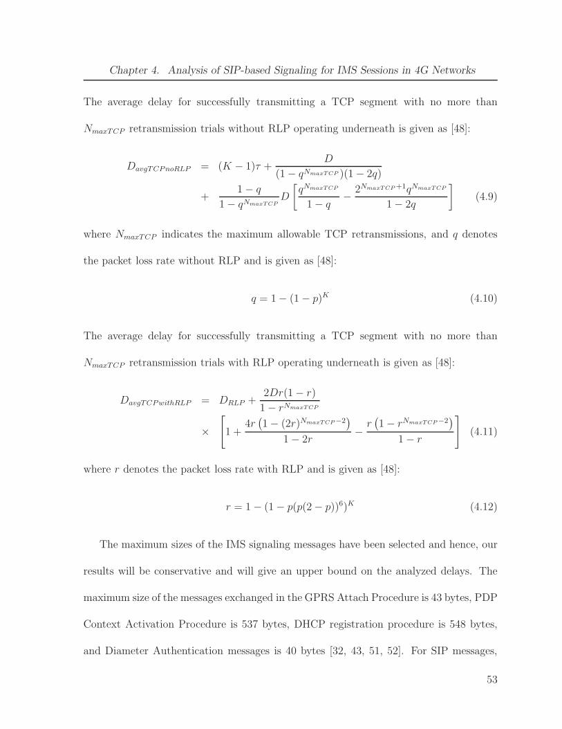
Chapter 4. Analysis of SIP-based Signaling for IMS Sessions in 4G Networks
The average delay for successfully transmitting a TCP segment with no more than
NmaxTCP retransmission trials without RLP operating underneath is given as [48]:
DavgTCPnoRLP = (K − 1)τ +D
(1 − qNmaxTCP )(1 − 2q)
+1 − q
1 − qNmaxTCPD
[
qNmaxTCP
1 − q−
2NmaxTCP +1qNmaxTCP
1 − 2q
]
(4.9)
where NmaxTCP indicates the maximum allowable TCP retransmissions, and q denotes
the packet loss rate without RLP and is given as [48]:
q = 1 − (1 − p)K (4.10)
The average delay for successfully transmitting a TCP segment with no more than
NmaxTCP retransmission trials with RLP operating underneath is given as [48]:
DavgTCPwithRLP = DRLP +2Dr(1 − r)
1 − rNmaxTCP
×
[
1 +4r(
1 − (2r)NmaxTCP−2)
1 − 2r−r(
1 − rNmaxTCP −2)
1 − r
]
(4.11)
where r denotes the packet loss rate with RLP and is given as [48]:
r = 1 − (1 − p(p(2 − p))6)K (4.12)
The maximum sizes of the IMS signaling messages have been selected and hence, our
results will be conservative and will give an upper bound on the analyzed delays. The
maximum size of the messages exchanged in the GPRS Attach Procedure is 43 bytes, PDP
Context Activation Procedure is 537 bytes, DHCP registration procedure is 548 bytes,
and Diameter Authentication messages is 40 bytes [32, 43, 51, 52]. For SIP messages,
53

Chapter 4. Analysis of SIP-based Signaling for IMS Sessions in 4G Networks
Table 4.1: Size of SIP messages involved in IMS signaling
SIP Message Type Compressed Size (with SigComp)
INVITE 810
REGISTER 225
183 SESSION PROGRESS 260
PRACK 260
100 TRYING 260
180 RINGING 260
200 OK 100
ACK 60
SUBSCRIBE 100
NOTIFY 100
401 UNAUTHORIZED 100
UPDATE 260
SigComp has been used which was developed by IETF for compression of general text-
based protocols. It has been shown in [53] that SIP/SDP message sizes can be reduced by
as much as 88% using SigComp with negligible compression/decompression time. The
compression rate for the initial SIP messages such as INVITE, REGISTER has been
chosen to be 55% and for the subsequent SIP messages to be 80%. The SIP message
sizes that have been selected according to standards [29, 54] are shown in Table 4.1.
54

Chapter 4. Analysis of SIP-based Signaling for IMS Sessions in 4G Networks
We consider 9.6 kbps, 19.2 kbps, 128 kbps channel for 3G network; and 2 Mbps, 11
Mbps channel for IEEE 802.11 WLAN. We need to calculate the values of K i.e. the
number of RLP frames in a packet, for the above mentioned channel rates. RLP frame
duration or inter-frame time τ is assumed to be 20 ms for 3G AN [48]. We proceed as
follows for calculation of value of K for 9.6 kbps channel: Number of bytes in each frame
9.6× 103 × 20× 10−3 × 1
8= 24 bytes. For GPRS attach procedure, and 9.6 kbps channel;
the value of K comes out to be ⌈43
24⌉ = 2. WLAN frame duration is assumed to be 3.5
ms and inter-frame time τ is taken to be 1 ms and is independent of the channel bit rate
[32]. For 2 Mbps channel: Number of bytes in each frame 2× 106 × 3.5× 10−3 × 1
8= 875
bytes. For dynamic host configuration protocol (DHCP) registration procedure, and 2
Mbps channel; the value of K comes out to be ⌈548
875⌉ = 1. The values of K obtained for
different messages following the same methodology are shown in Table 4.2. Only required
values of K are calculated; for example, since GPRS attach procedure is required only
for attaching to UMTS network not for WLAN, we need not calculate the values of K
for 2 Mbps and 11 Mbps channels corresponding to WLAN. We take care of the value of
K for a particular signaling message in our analysis.
For GPRS attach procedure, 9 message are exchanged between UE (SN or CN) and
the SGSN of the new UMTS network [51] as shown in Figure 4.1. RLP is used on the top
of MAC layer in 3G networks to improve the bit error rate (BER) performance. Hence,
transmission delay for GPRS attach procedure Dtrans−gprsattach is given by:
Dtrans−gprsattach = 9 ×DavgRLP (4.13)
55

Chapter 4. Analysis of SIP-based Signaling for IMS Sessions in 4G Networks
Table 4.2: Values of K for signaling messages in different channel rates
Message Types 9.6 kbps 19.2 kbps 128 kbps 2 Mbps 11 Mbps
GPRS attach 2 1 1 - -
PDP context activation 23 12 2 - -
DHCP registration - - - 1 1
SIP INVITE 34 17 3 1 1
SIP REGISTER 10 5 1 1 1
SIP 183 SESSION PROGRESS 11 6 1 1 1
SIP 180 RINGING 11 6 1 1 1
SIP PRACK 11 6 1 1 1
SIP 100 TRYING 11 6 1 1 1
SIP UPDATE 11 6 1 1 1
SIP 200 OK 5 3 1 1 1
SIP SUBSCRIBE 5 3 1 1 1
SIP NOTIFY 5 3 1 1 1
SIP 401 UNAUTHORIZED 5 3 1 1 1
SIP ACK 3 2 1 1 1
56

Chapter 4. Analysis of SIP-based Signaling for IMS Sessions in 4G Networks
Figure 4.1: GPRS attach procedure [51].
57

Chapter 4. Analysis of SIP-based Signaling for IMS Sessions in 4G Networks
For PDP context activation procedure, 2 message exchanges are there between UE and
SGSN [51] as depicted in Figure 4.2. Therefore, transmission delay for PDP context
activation procedure Dtrans−pdpcontext is given as:
Dtrans−pdpcontext = 2 ×DavgRLP (4.14)
For DHCP registration procedure, 4 message exchanges are there between UE and DHCP
server [52] as shown in Figure 4.3. No RLP is used in case of WLAN because of much
higher bandwidth and indoor operations. Therefore, DHCP registration procedure trans-
mission delay Dtrans−dhcp is given by:
Dtrans−dhcp = 4 ×DavgTCPnoRLP (4.15)
For IMS registration procedure including subscription to “reg Event” state, 8 message
exchanges are there between UE and the P-CSCF server of the IMS network [41], [42]
as shown in Figure 4.4. When registration procedure takes place in the 3G AN, the
transmission delay for IMS registrion procedure Dtrans−imsreg3g is given as:
Dtrans−imsreg3g = 8 ×DavgTCPwithRLP (4.16)
When registration procedure takes place in WLAN AN, the transmission delay for IMS
registration procedure Dtrans−imsregwlan is given as:
Dtrans−imsregwlan = 8 ×DavgTCPnoRLP (4.17)
For IMS session setup, 13 message exchanges are involved between SN and P-CSCF of
the visited IMS network and 13 message exchanges are involved between P-CSCF of the
58

Chapter 4. Analysis of SIP-based Signaling for IMS Sessions in 4G Networks
terminating IMS network and CN [41], [42] as shown in Figure 4.5. When SN is in UMTS
network and CN is in WLAN and vice versa, the IMS session setup transmission delay
Dtrans−setup−uw/wu is given by:
Dtrans−setup−uw/wu = 12 ×DavgTCPwithRLP + 12 ×DavgTCPnoRLP (4.18)
When SN as well as CN are in 3G network, the IMS session setup transmission delay
Dtrans−setup−uu is given as:
Dtrans−setup−uu = 24 ×DavgTCPwithRLP (4.19)
When SN as well as CN are in WLAN, the IMS session setup transmission delayDtrans−setup−ww
is given by:
Dtrans−setup−ww = 24 ×DavgTCPnoRLP (4.20)
4.1.2 Processing Delay
We calculate the processing delay for different entities in the IMS signaling path. The
processing delay for some of the nodes such as HSS, home location register (HLR), and
equipment identification register (EIR) mainly consists of the address lookup table delay.
When a query is sent to HSS, HLR, or EIR for a particular IP address, the HSS, HLR,
or EIR have to lookup their table for the given IP address. We assume that HSS, HLR,
and EIR tables contains the list of all the users N in the network. The IP address lookup
is the main component involved in the processing delay for databases. It has been shown
that cache line size can be used to help in multiway search; and binary search can be
59

Chapter 4. Analysis of SIP-based Signaling for IMS Sessions in 4G Networks
adapted to perform multiple-column search for long length IP addresses [44]. For the
rest of the network entities, we assume a fixed processing delay mainly consisting of the
delay involved in the encapsulation and decapsulation of packets. The processing delay
in nanoseconds at the HSS, HLR or EIR can be approximated as:
dproc−hss/hlr/eir = dproc−ed + 100
(
logk+1N +L
S
)
ns (4.21)
where L is the IP address length in bits e.g. L is 32 for IPv4 and 128 for IPv6, S is
the machine word size in bits, and k is a system-dependent constant. We have used the
multiplication factor of 100 ns in the above equation because it has been shown in [44]
that the lookup time is increased by around 100 ns for each memory access. Considering
the signaling flows in the GPRS attach procedure, the processing delay for the GPRS
attach procedure Dproc−gprsattach can be given as:
Dproc−gprsattach = 4dproc−sn + 9dproc−nsgsn + 2dproc−osgsn + dproc−eir + 3dproc−hlr (4.22)
where dproc−sn, dproc−nsgsn, dproc−osgsn, dproc−eir, and dproc−hlr indicates a unit packet pro-
cessing delay at SN, New SGSN, Old SGSN, EIR and HLR respectively. The processing
delay for the PDP context activation procedure Dproc−pdpcontext can be given as:
Dproc−pdpcontext = dproc−sn + 3dproc−sgsn + dproc−dns + 3dproc−ggsn
+ dproc−radius + dproc−dhcp (4.23)
where dproc−sgsn, dproc−dns, dproc−ggsn, dproc−radius, and dproc−dhcp indicates a unit packet
processing delay at SGSN, domain name system (DNS) server, GGSN, Radius server,
60

Chapter 4. Analysis of SIP-based Signaling for IMS Sessions in 4G Networks
and DHCP server, respectively. The processing delay for the DHCP registration process
Dproc−dhcp can be given as:
Dproc−dhcp = 2dproc−sn + 2dproc−dhcp (4.24)
The processing delay for the IMS registration process Dproc−imsreg can be given as:
Dproc−imsreg = 4dproc−sn + 10dproc−pcscf + 6dproc−icscf + 4dproc−hss + 8dproc−scscf (4.25)
where dproc−pcscf , dproc−icscf , dproc−hss, and dproc−scscf denotes the unit packet processing
delay at P-CSCF, I-CSCF, HSS, and S-CSCF, respectively. The processing delay for the
IMS session setup Dproc−imssetup can be given as:
Dproc−setup = 7dproc−sn + 26dproc−pcscf + 26dproc−scscf + 6dproc−icscf
+ dproc−hss + 6dproc−cn (4.26)
where dproc−cn denotes the unit packet processing delay at the CN.
4.1.3 Queueing Delay
We calculate the queueing delays for different network entities involved in the IMS sig-
naling. Delay to reach from SN to CN depends on the queueing delay at each of the
intervening queues which itself depends upon the number of packets at each queue. Also
waiting time of a packet in a queue depends upon the number of packets in that queue.
We have assumed M/M/1 queues for the network entities. A queueing network is said to
be in equilibrium if a stationary state exists. For an M/M/1 queue in equilibrium state,
61
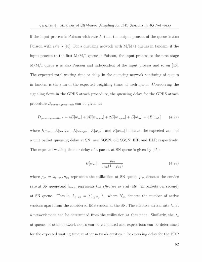
Chapter 4. Analysis of SIP-based Signaling for IMS Sessions in 4G Networks
if the input process is Poisson with rate λ, then the output process of the queue is also
Poisson with rate λ [46]. For a queueing network with M/M/1 queues in tandem, if the
input process to the first M/M/1 queue is Poisson, the input process to the next stage
M/M/1 queue is is also Poisson and independent of the input process and so on [45].
The expected total waiting time or delay in the queueing network consisting of queues
in tandem is the sum of the expected weighting times at each queue. Considering the
signaling flows in the GPRS attach procedure, the queueing delay for the GPRS attach
procedure Dqueue−gprsattach can be given as:
Dqueue−gprsattach = 4E[wsn] + 9E[wnsgsn] + 2E[wosgsn] + E[weir] + 3E[whlr] (4.27)
where E[wsn], E[wnsgsn], E[wosgsn], E[weir], and E[whlr] indicates the expected value of
a unit packet queueing delay at SN, new SGSN, old SGSN, EIR and HLR respectively.
The expected waiting time or delay of a packet at SN queue is given by [45]:
E[wsn] =ρsn
µsn(1 − ρsn)(4.28)
where ρsn = λe−sn/µsn represents the utilization at SN queue, µsn denotes the service
rate at SN queue and λe−sn represents the effective arrival rate (in packets per second)
at SN queue. That is, λe−sn =∑
i∈Nsnλi, where Nsn denotes the number of active
sessions apart from the considered IMS session at the SN. The effective arrival rate λe at
a network node can be determined from the utilization at that node. Similarly, the λe
at queues of other network nodes can be calculated and expressions can be determined
for the expected waiting time at other network entities. The queueing delay for the PDP
62

Chapter 4. Analysis of SIP-based Signaling for IMS Sessions in 4G Networks
context activation procedure Dqueue−pdpcontext can be given as:
Dqueue−pdpcontext = E[wsn]+3E[wsgsn]+E[wdns]+3E[wggsn]+E[wradius]+E[wdhcp] (4.29)
where E[wsgsn], E[wdns], E[wggsn], E[wradius], and E[wdhcp] indicates the expected value
of a unit packet queueing delay at SGSN, DNS server, GGSN, Radius server, and DHCP
server, respectively. The queueing delay for the DHCP registration process Dqueue−dhcp
can be given as:
Dqueue−dhcp = 2E[wsn] + 2E[wdhcp] (4.30)
The queueing delay for the IMS registration process Dqueue−imsreg can be given as:
Dqueue−imsreg = 4E[wsn] + 10E[wpcscf ] + 6E[wicscf ] + 4E[whss] + 8E[wscscf ] (4.31)
where E[wpcscf ], E[wicscf ], E[whss], and E[wscscf ] denotes the expected value of a unit
packet queueing delay at P-CSCF, I-CSCF, HSS, and S-CSCF, respectively. The queue-
ing delay for the IMS session setup Dqueue−imssetup can be given as:
Dqueue−imssetup = 7E[wsn] + 26E[wpcscf ] + 26E[wscscf ] + 6E[wicscf ]
+ E[whss] + 6E[wcn] (4.32)
where E[wcn] denotes the expected value of a unit packet queueing delay at the CN.
4.1.4 Total Delay
We calculate the total delay for different procedures involved in the IMS session estab-
lishment. The delay for GPRS attach procedure is given as:
Dgprsattach = Dtrans−gprsattach +Dproc−gprsattach +Dqueue−gprsattach (4.33)
63

Chapter 4. Analysis of SIP-based Signaling for IMS Sessions in 4G Networks
The delay for PDP context activation procedure is given by:
Dpdpcontext = Dtrans−pdpcontext +Dproc−pdpcontext +Dqueue−pdpcontext (4.34)
The delay for DHCP registration procedure is given as:
Ddhcp = Dtrans−dhcp +Dproc−dhcp +Dqueuedhcp (4.35)
IMS Registration Procedure Delay
The delay for IMS registration procedure when the registration takes place in 3G AN is
given as:
Dimsreg3g = Dtrans−imsreg3g +Dproc−imsreg +Dqueueimsreg (4.36)
The delay for IMS registration procedure when the registration takes place in WLAN
AN is given as:
Dimsregwlan = Dtrans−imsregwlan +Dproc−imsreg +Dqueueimsreg (4.37)
IMS Session Setup Delay
The delay for IMS session setup when SN is in UMTS network and CN is in WLAN and
vice versa is given by:
Dsetup−uw/wu = Dtrans−setup−uw/wu +Dproc−setup +Dqueue−setup (4.38)
The delay for IMS session setup when SN as well as CN are in 3G network is given by:
Dsetup−uu = Dtrans−setup−uu +Dproc−setup +Dqueue−setup (4.39)
64

Chapter 4. Analysis of SIP-based Signaling for IMS Sessions in 4G Networks
The delay for IMS session setup when SN as well as CN are in WLAN is given as:
Dsetup−ww = Dtrans−setup−ww +Dproc−setup +Dqueue−setup (4.40)
Note that if the SN or the CN have not registered with the IMS network, then before the
IMS session establishment, they have to undergo IMS registration process. In that case,
the delay for IMS registration will be added to the total session setup delay.
IMS Session Re-establishment Delay
To re-establish a session after an SN or CN has undergone a vertical handoff, it needs to
send a SIP re-INVITE message to the other terminal. We separately analyze the cases
involved in the IMS session re-establishment after a vertical handoff.
SN moves to a new 3G network For this case, the steps performed by the SN are: (i)
GPRS attach procedure, (ii) PDP context activation procedure, (iii) re-establishment of
IMS session using SIP re-INVITE message. Within this case, further two cases arise, i.e.,
whether the CN is in WLAN or in UMTS. When the CN is in WLAN, the transmission
delay Dvho−uw is given as:
Dvho−uw = Dgprs−attach +Dpdp−context +Dsetup−uw (4.41)
When the CN is in 3G network, the transmission delay Dvho−uu is given as:
Dvho−uu = Dgprs−attach +Dpdp−context +Dsetup−uu (4.42)
65

Chapter 4. Analysis of SIP-based Signaling for IMS Sessions in 4G Networks
SN moves to a WLAN For this case, the steps performed by the SN are: (i) DHCP
registration procedure, (ii) re-establishment of IMS session using SIP re-INVITE message.
Within this case, further two cases arise, i.e., whether the CN is in WLAN or in UMTS.
When the CN is in WLAN, the transmission delay Dvho−ww is given as:
Dvho−ww = Ddhcp +Dsetup−ww (4.43)
When the CN is in 3G network, the transmission delay Dvho−wu is given as:
Dvho−wu = Ddhcp +Dsetup−wu (4.44)
4.2 Numerical Results
In this section, we present the numerical results for the delay analysis of SIP-based
signaling for IMS sessions. The parameter values selected for the analysis are mentioned
hereafter. The value of end-to-end frame propagation delay D for 9.6 kbps, 19.2 kbps, and
128 kbps channel is taken equal to 100 ms whereas for 2 Mbps, and 11 Mbps channel, the
valued of D is chosen to be 0.27 ms and 0.049 ms, respectively [32]. Frame duration T as
well as inter-frame time τ is assumed to be 20 ms for 3G AN [48]. WLAN frame duration
is assumed to be 3.5 ms and inter-frame time τ is taken to be 1 ms and is independent of
the channel bit rate [32]. Total number of users N in the network is taken to be 18600 in
accordance with the previous chapter. The IP address length L and processor machine
word size S are taken to be 32 bits. The system dependent constant value k is equal
to 5 [44]. The maximum number of RLP retransmissions n and maximum number of
66
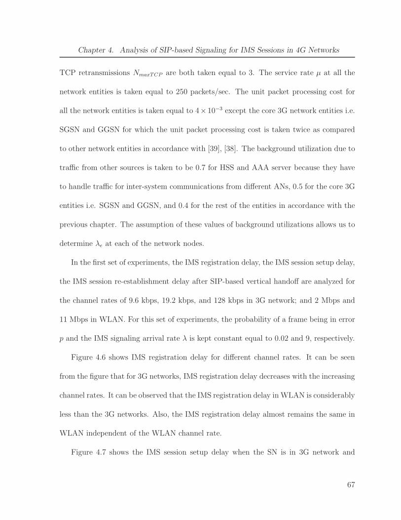
Chapter 4. Analysis of SIP-based Signaling for IMS Sessions in 4G Networks
TCP retransmissions NmaxTCP are both taken equal to 3. The service rate µ at all the
network entities is taken equal to 250 packets/sec. The unit packet processing cost for
all the network entities is taken equal to 4×10⁻³ except the core 3G network entities i.e.
SGSN and GGSN for which the unit packet processing cost is taken twice as compared
to other network entities in accordance with [39], [38]. The background utilization due to
traffic from other sources is taken to be 0.7 for HSS and AAA server because they have
to handle traffic for inter-system communications from different ANs, 0.5 for the core 3G
entities i.e. SGSN and GGSN, and 0.4 for the rest of the entities in accordance with the
previous chapter. The assumption of these values of background utilizations allows us to
determine λe at each of the network nodes.
In the first set of experiments, the IMS registration delay, the IMS session setup delay,
the IMS session re-establishment delay after SIP-based vertical handoff are analyzed for
the channel rates of 9.6 kbps, 19.2 kbps, and 128 kbps in 3G network; and 2 Mbps and
11 Mbps in WLAN. For this set of experiments, the probability of a frame being in error
p and the IMS signaling arrival rate λ is kept constant equal to 0.02 and 9, respectively.
Figure 4.6 shows IMS registration delay for different channel rates. It can be seen
from the figure that for 3G networks, IMS registration delay decreases with the increasing
channel rates. It can be observed that the IMS registration delay in WLAN is considerably
less than the 3G networks. Also, the IMS registration delay almost remains the same in
WLAN independent of the WLAN channel rate.
Figure 4.7 shows the IMS session setup delay when the SN is in 3G network and
67

Chapter 4. Analysis of SIP-based Signaling for IMS Sessions in 4G Networks
CN is in WLAN for different combinations of 3G and WLAN channel rates. It can be
observed that the IMS session setup delay is greatly effected by the 3G channel rate
i.e. IMS session setup delay decreases considerably as the 3G channel rate increases.
Another interesting observation is that the IMS session setup delay is negligibly effected
by changing the WLAN channel rate.
Figure 4.8 shows the IMS session setup delay when SN as well as CN are in 3G
network for different combination of 3G channel rates. It can be observed from the figure
that the IMS session setup delay decreases with the increasing 3G channel rates.
Figure 4.9 shows the IMS session setup delay when SN as well as CN are in WLAN. It
can be observed that the IMS session setup delay in this case is much less as compared to
the cases shown in Figure 4.7 and Figure 4.8. Also, there is negligible effect of changing
WLAN channel rate in this case on IMS session setup delay.
Figure 4.10 shows the IMS session re-establishment delay when SN moves to a 3G
network and CN is in WLAN for different combination of 3G and WLAN channel rates. It
can be observed that the IMS session re-establishment delay decreases with the increasing
3G channel rate and the change in WLAN channel rate has negligible effect on the IMS
session re-establishment delay.
Figure 4.11 shows the IMS session re-establishment delay when SN moves to a 3G
network and CN is in 3G network for different combination of 3G channel rates. It can
be seen that the IMS session re-establishment delay decreases when either the SN 3G
channel rate or CN 3G channel rate or both increases.
68
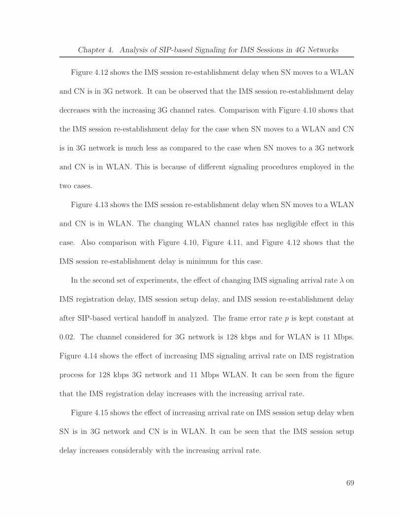
Chapter 4. Analysis of SIP-based Signaling for IMS Sessions in 4G Networks
Figure 4.12 shows the IMS session re-establishment delay when SN moves to a WLAN
and CN is in 3G network. It can be observed that the IMS session re-establishment delay
decreases with the increasing 3G channel rates. Comparison with Figure 4.10 shows that
the IMS session re-establishment delay for the case when SN moves to a WLAN and CN
is in 3G network is much less as compared to the case when SN moves to a 3G network
and CN is in WLAN. This is because of different signaling procedures employed in the
two cases.
Figure 4.13 shows the IMS session re-establishment delay when SN moves to a WLAN
and CN is in WLAN. The changing WLAN channel rates has negligible effect in this
case. Also comparison with Figure 4.10, Figure 4.11, and Figure 4.12 shows that the
IMS session re-establishment delay is minimum for this case.
In the second set of experiments, the effect of changing IMS signaling arrival rate λ on
IMS registration delay, IMS session setup delay, and IMS session re-establishment delay
after SIP-based vertical handoff in analyzed. The frame error rate p is kept constant at
0.02. The channel considered for 3G network is 128 kbps and for WLAN is 11 Mbps.
Figure 4.14 shows the effect of increasing IMS signaling arrival rate on IMS registration
process for 128 kbps 3G network and 11 Mbps WLAN. It can be seen from the figure
that the IMS registration delay increases with the increasing arrival rate.
Figure 4.15 shows the effect of increasing arrival rate on IMS session setup delay when
SN is in 3G network and CN is in WLAN. It can be seen that the IMS session setup
delay increases considerably with the increasing arrival rate.
69

Chapter 4. Analysis of SIP-based Signaling for IMS Sessions in 4G Networks
Figure 4.16 shows the effect of increasing arrival rate on IMS session re-establishment
delay when SN moves to a 3G network and CN is in WLAN. It can be observed that
the IMS session re-establishment delay increases considerably with the increasing arrival
rates.
In the third set of experiments, the effect of changing frame error rate p on IMS
registration delay, IMS session setup delay, and IMS session re-establishment delay after
SIP-based vertical handoff in analyzed. The arrival rate λ is kept constant at 9 for this set
of experiments. The channel considered for 3G network is 128 kbps and for WLAN is 11
Mbps. Figure 4.17 shows the effect of increasing frame error rate on the IMS registration
delay. It can be seen that increasing frame error rate has negligible effect on the IMS
registration delay. This is because of the use of RLP which improves the efficiency in the
error prone environments as well.
Figure 4.18 shows the effect of increasing frame error rate on the IMS session setup
delay. It can be observed that the increasing frame error rate has negligible effect on the
IMS session setup delay.
Figure 4.19 shows the effect of increasing frame error rate on the IMS session re-
establishment delay. It can be noticed that the increasing frame error rate has negligible
effect on the IMS session re-establishment delay.
70

Chapter 4. Analysis of SIP-based Signaling for IMS Sessions in 4G Networks
4.3 Summary
In this chapter, we analyzed the delay for IMS registration, IMS session establishment
and IMS session re-establishment procedures after undergoing a vertical handoff. The
delay analysis is comprehensive since it takes into account transmission, processing, and
queueing delays at the network entities. Numerical results indicate that increasing the
3G channel rate can significantly decrease the IMS registration, IMS session setup, and
IMS session re-establishment delay but changing the WLAN channel rate has negligible
effect on the IMS signaling delay. However, the IMS signaling delay in WLAN is much
less as compared to that in the 3G network. The IMS registration, IMS session setup,
and IMS session re-establishment delay increase with the increase in the arrival rate but
are effected negligibly with the increasing frame error rate.
71
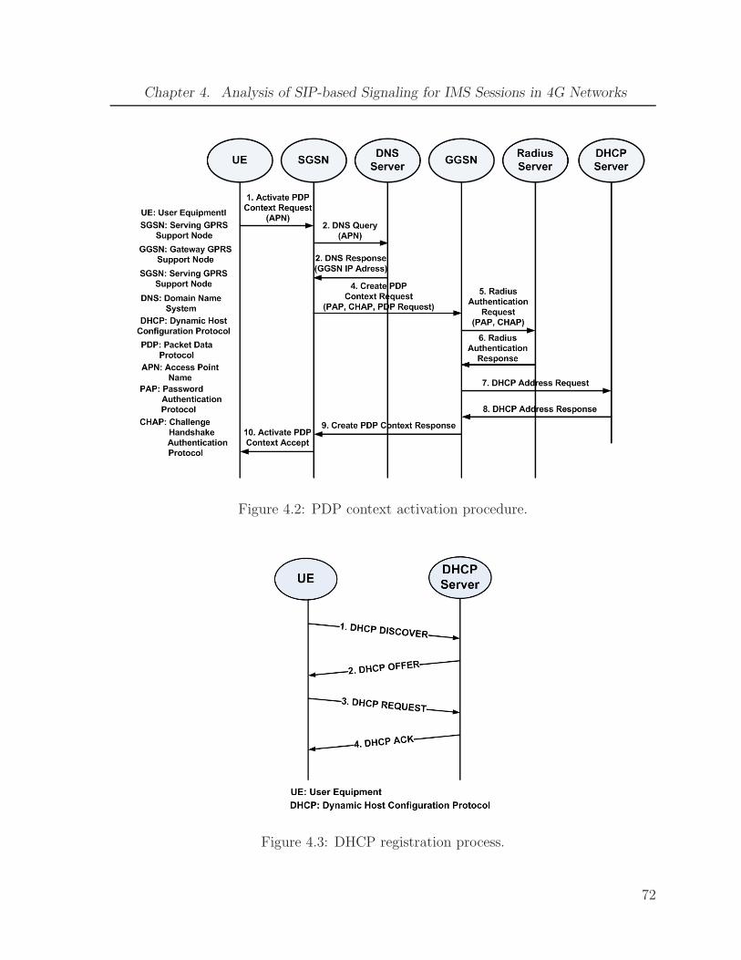
Chapter 4. Analysis of SIP-based Signaling for IMS Sessions in 4G Networks
Figure 4.2: PDP context activation procedure.
Figure 4.3: DHCP registration process.
72

Chapter 4. Analysis of SIP-based Signaling for IMS Sessions in 4G Networks
Figure 4.4: IMS registration process [41], [42].73

Chapter 4. Analysis of SIP-based Signaling for IMS Sessions in 4G Networks
Figure 4.5: IMS session setup procedure [41], [42].
74

Chapter 4. Analysis of SIP-based Signaling for IMS Sessions in 4G Networks
9.6 19.2 128 2K 11K0
0.2
0.4
0.6
0.8
1
1.2
1.4
1.6
1.8
2
Channel Rates (kbps)
IMS
Reg
istr
atio
n D
elay
(se
cond
s)
Figure 4.6: IMS registration delay for different channel rates for fixed λ = 9 and p = 0.02
9.6, 2 19.2, 2 128, 2 9.6, 11 19.2, 11 128, 110
0.5
1
1.5
2
2.5
3
SN 3G channel (kbps), CN WLAN channel (Mbps)
IMS
Ses
sion
Set
up D
elay
(s)
Figure 4.7: IMS session setup delay for different channel rates when SN is in 3G network
and CN is in WLAN for fixed λ = 9 and p = 0.02
75
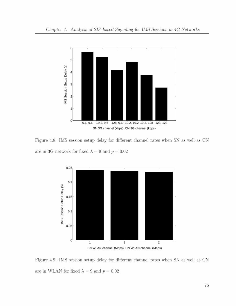
Chapter 4. Analysis of SIP-based Signaling for IMS Sessions in 4G Networks
9.6, 9.6 19.2, 9.6 128, 9.6 19.2, 19.2 19.2, 128 128, 1280
1
2
3
4
5
6
SN 3G channel (kbps), CN 3G channel (kbps)
IMS
Ses
sion
Set
up D
elay
(s)
Figure 4.8: IMS session setup delay for different channel rates when SN as well as CN
are in 3G network for fixed λ = 9 and p = 0.02
1 2 30
0.05
0.1
0.15
0.2
0.25
SN WLAN channel (Mbps), CN WLAN channel (Mbps)
IMS
Ses
sion
Set
up D
elay
(s)
Figure 4.9: IMS session setup delay for different channel rates when SN as well as CN
are in WLAN for fixed λ = 9 and p = 0.02
76

Chapter 4. Analysis of SIP-based Signaling for IMS Sessions in 4G Networks
9.6, 2 19.2, 2 128, 2 9.6, 11 19.2, 11 128, 110
1
2
3
4
5
6
SN 3G channel (kbps), CN WLAN channel (Mbps)
Ses
sion
Re−
esta
blis
hmen
t Del
ay (
s)
Figure 4.10: IMS session re-establishment delay for different channel rates when SN is in
3G network and CN is in WLAN for fixed λ = 9 and p = 0.02
9.6,9.6 19.2,9.6 128,9.6 128,19.2 9.6,19.2 9.6,128 19.2,19.2 19.2,128 128,1280
1
2
3
4
5
6
7
8
9
SN 3G channel (kbps), CN 3G channel (kbps)
Ses
sion
Re−
esta
blis
hmen
t Del
ay (
s)
Figure 4.11: IMS session re-establishment delay for different channel rates when SN as
well as CN are in 3G network for fixed λ = 9 and p = 0.02
77

Chapter 4. Analysis of SIP-based Signaling for IMS Sessions in 4G Networks
2, 9.6 2, 19.2 2, 128 11, 9.6 11, 19.2 11, 1280
0.5
1
1.5
2
2.5
3
SN WLAN channel (Mbps), CN 3G channel (kbps)
Ses
sion
Re−
esta
blis
hmen
t Del
ay (
s)
Figure 4.12: IMS session re-establishment delay for different channel rates when SN is in
WLAN and CN is in 3G network for fixed λ = 9 and p = 0.02
2, 2 11, 2 2, 11 11, 110
0.05
0.1
0.15
0.2
0.25
SN WLAN channel (Mbps), CN WLAN channel (Mbps)
Ses
sion
Re−
esta
blis
hmen
t Del
ay (
s)
Figure 4.13: IMS session re-establishment delay for different channel rates when SN as
well as CN are in WLAN for fixed λ = 9 and p = 0.02
78
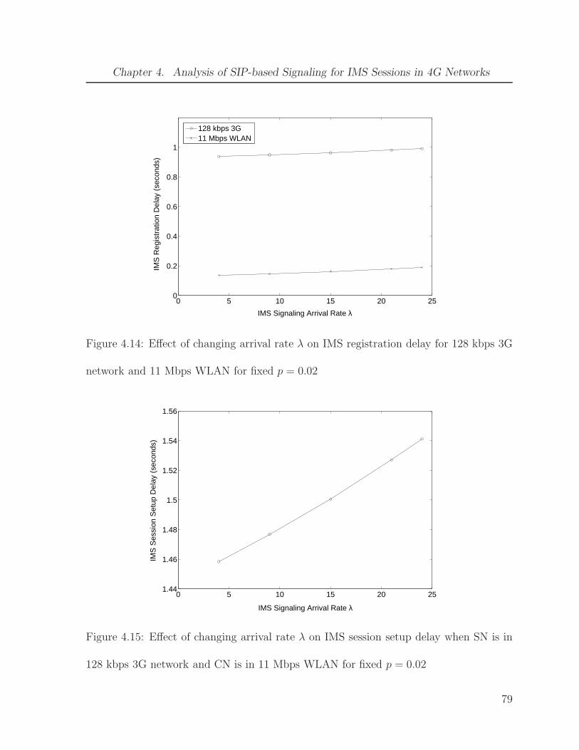
Chapter 4. Analysis of SIP-based Signaling for IMS Sessions in 4G Networks
0 5 10 15 20 250
0.2
0.4
0.6
0.8
1
IMS Signaling Arrival Rate λ
IMS
Reg
istr
atio
n D
elay
(se
cond
s)
128 kbps 3G11 Mbps WLAN
Figure 4.14: Effect of changing arrival rate λ on IMS registration delay for 128 kbps 3G
network and 11 Mbps WLAN for fixed p = 0.02
0 5 10 15 20 251.44
1.46
1.48
1.5
1.52
1.54
1.56
IMS Signaling Arrival Rate λ
IMS
Ses
sion
Set
up D
elay
(se
cond
s)
Figure 4.15: Effect of changing arrival rate λ on IMS session setup delay when SN is in
128 kbps 3G network and CN is in 11 Mbps WLAN for fixed p = 0.02
79
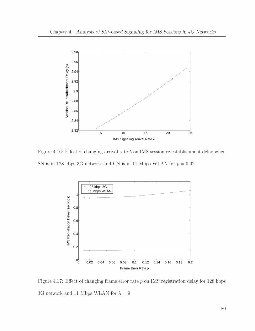
Chapter 4. Analysis of SIP-based Signaling for IMS Sessions in 4G Networks
0 5 10 15 20 252.82
2.84
2.86
2.88
2.9
2.92
2.94
2.96
2.98
IMS Signaling Arrival Rate λ
Ses
sion
Re−
esta
blis
hmen
t Del
ay (
s)
Figure 4.16: Effect of changing arrival rate λ on IMS session re-establishment delay when
SN is in 128 kbps 3G network and CN is in 11 Mbps WLAN for p = 0.02
0 0.02 0.04 0.06 0.08 0.1 0.12 0.14 0.16 0.18 0.20
0.2
0.4
0.6
0.8
1
Frame Error Rate p
IMS
Reg
istr
atio
n D
elay
(se
cond
s)
128 kbps 3G11 Mbps WLAN
Figure 4.17: Effect of changing frame error rate p on IMS registration delay for 128 kbps
3G network and 11 Mbps WLAN for λ = 9
80

Chapter 4. Analysis of SIP-based Signaling for IMS Sessions in 4G Networks
0 0.02 0.04 0.06 0.08 0.1 0.12 0.14 0.16 0.18 0.2
1.5
1.55
1.6
1.65
1.7
Frame Error Rate p
IMS
Ses
sion
Set
up D
elay
(s)
Figure 4.18: Effect of changing frame error rate p on IMS session setup when SN is in
128 kbps 3G network and CN is in 11 Mbps WLAN for λ = 9
0 0.02 0.04 0.06 0.08 0.1 0.12 0.14 0.16 0.18 0.22.8
2.85
2.9
2.95
3
3.05
3.1
3.15
3.2
3.25
3.3
Frame Error Rate p
Ses
sion
Re−
esta
blis
hmen
t Del
ay (
s)
Figure 4.19: Effect of changing frame error rate p on IMS session re-establishment delay
when SN is in 128 kbps 3G network and CN is in 11 Mbps WLAN for λ = 9
81
Bibliography
[1] 3GPP. IP Multimedia Subsystem (IMS); Stage 2. TS 23.228 (v7.3.0), March 2006.
[2] D. Geer. Building Converged Networks with IMS Technology. IEEE Computer,
38(11):14–16, November 2005.
[3] A.K. Salkintzis. WLAN/3G Interworking Architecture for Next Generation Hybrid
Data Networks. In Proc. of IEEE International Conference on Communications
(ICC’04), Paris, France, June 2004.
[4] K.D. Wong and V.K. Varma. Supporting Real-Time IP Multimedia Services in
UMTS. IEEE Communications Magazine, 41(11):148–155, November 2003.
[5] S. Tsao and C. Lin. Design and Evaluation of UMTS-WLAN Interworking Strate-
gies. In Proc. of IEEE Vehicular Technology Conference (VTC’02), Birmingham,
Alabama, September 2002.
[6] R. Rajavelsamy, V. Jeedigunta, B. Holur, M. Choudhary, and O. Song. Performance
Evaluation of VoIP over 3G-WLAN Interworking System. In Proc. of IEEE Wireless
Communications and Networking Conference (WCNC’05), Atlanta, Georgia, March
2005.
82
Bibliography
[7] K. Ahmavaara, H. Haverinen, and R. Pichna. Interworking Architecture be-
tween 3GPP and WLAN Systems. IEEE Communications Magazine, 41(11):74–81,
November 2003.
[8] P. Pinto, L. Bernardo, and P. Sobral. Seamless Continuity of PS-Services in
WLAN/3G Interworking. Elsevier Computer Communications, 29(8):1055–1064,
May 2006.
[9] G. Ruggeri, A. Iera, and S. Polito. 802.11-Based Wireless LAN and UMTS Inter-
working: Requirements, Proposed Solutions and Open Issues. Elsevier Computer
Networks, 47(2):151–166, February 2005.
[10] H.S. Mahmood and B. Gage. An Architecture for Integrating CDMA2000 and 802.11
WLAN Networks. In Proc. of IEEE Vehicular Technology Conference (VTC’03),
Orlando, Florida, October 2003.
[11] B.G. Evans, M. Werner, E. Lutz, M. Bousquet, G.E. Corazza, G. Maral, R. Rumeau,
and E. Ferro. Integration of Satellite and Terrestrial Systems in Future Multimedia
Communications. IEEE Wireless Communications, 12(5):72–80, October 2005.
[12] D. Ayyagari and A. Ephremides. A Satellite-Augmented Cellular Network Concept.
ACM Wireless Networks, 4(2):189–198, February 1998.
[13] V.Y.H. Kueh, R. Tafazolli, and B.G. Evans. Performance Analysis of Session Initi-
ation Protocol Based Call Set-up over Satellite-UMTS Network. Elsevier Computer
Communications, 28(12):1416–1427, July 2005.
83

Bibliography
[14] Z. Sun, D. He, H.S. Cruickshank, L. Liang, A. Sanchez, C. Miguel, V. Schena,
C. Tocci, and B. Carro. Scalable Architecture and Evaluation for Multiparty Con-
ferencing over Satellite Links. IEEE Journal on Selected Areas in Communications,
22(3):594–605, April 2004.
[15] L. Fan, R.E. Sheriff, and J.G. Gardiner. Satellite-UMTS Service Provision Using IP-
Based Technology. In Proc. of IEEE Vehicular Technology Conference (VTC’2000),
Tokyo, Japan, May 2000.
[16] V.Y.H. Kueh, N. Wang, and B. Evans. Performance Evaluation of Conference Cre-
ation Signalling over Satellite UMTS. In Proc. of IEEE Vehicular Technology Con-
ference (VTC’05), Stockholm, Sweden, June 2005.
[17] A. Ghosh, D.R. Wolter, J.G. Andrews, and R. Chen. Broadband Wireless Access
with WiMax/802.16: Current Performance Benchmarks and Future Potential. IEEE
Communications Magazine, 43(2):129–136, February 2005.
[18] Q. Nguyen-Vuong, L. Fiat, and N. Agoulmine. An Architecture for UMTS-WIMAX
Interworking. In Proc. of 1st International Workshop on Broadband Convergence
Networks (BcN’06), Vancouver, Canada, April 2006.
[19] D. Kim and A. Ganz. Architecture for 3G and 802.16 Wireless Networks Integration
with QoS Support. In Proc. of 2nd International Conference on Quality of Service
in Heterogeneous Wired/Wireless Networks (QShine’05), Orlando, Florida, August
2005.
84
Bibliography
[20] J. Xie and I.F. Akyildiz. A Novel Distributed Dynamic Location Management
Scheme for Minimizing Signaling Costs in Mobile IP. IEEE Transactions on Mobile
Computing, 1(3):163–175, July-September 2002.
[21] S. Pack and Y. Choi. A Study on Performance of Hierarchical Mobile IPv6 in IP-
Based Cellular Networks. IEICE Transactions on Communications, E87-B(3):462–
469, March 2004.
[22] W. Wang and I.F. Akyildiz. A New Signaling Protocol for Intersystem Roaming in
Next-Generation Wireless Systems. IEEE Journal on Selected Areas in Communi-
cations, 19(10):2040–2052, October 2001.
[23] J.S.M. Ho and I.F. Akyildiz. Mobile User Location Update and Paging under Delay
Constraints. ACM Wireless Networks, 1(4):413–425, December 1995.
[24] I.F. Akyildiz and W. Wang. A Dynamic Location Management Scheme for Next-
Generation Multitier PCS Systems. IEEE Transactions on Wireless Communica-
tions, 1(1):178–189, January 2002.
[25] Y. Lin. Reducing Location Update Cost in a PCS Network. IEEE/ACM Transac-
tions on Networking, 5(1):25–33, February 1997.
[26] I.F. Akyildiz, J.S. M. Ho, and Y. Lin. Movement-Based Location Update and Selec-
tive Paging for PCS Networks. IEEE/ACM Transactions on Networking, 4(4):629–
638, August 1996.
85

Bibliography
[27] C. Rose and R. Yates. Minimizing the Average Cost of Paging under Delay Con-
straints. ACM Wireless Networks, 1(2):211–219, June 1995.
[28] G. Wan and E. Lin. Cost Reduction in Location Management using Semi-Realtime
Movement Information. ACM Wireless Networks, 5(4):245–256, July 1999.
[29] M. Melnyk and A. Jukan. On Signaling Efficiency for Call Setup in all-IP Wireless
Networks. In Proc. of IEEE International Conference on Communications (ICC’06),
June 2006.
[30] H. Fathi, S.S. Chakraborty, and R. Prasad. Optimization of SIP Session Setup
Delay for VoIP in 3G Wireless Networks. IEEE Transactions on Mobile Computing,
5(9):1121–1132, September 2006.
[31] H. Fathi, S.S. Chakraborty, and R. Prasad. On SIP Session Setup Delay for VoIP
Services over Correlated Fading Channels. IEEE Transactions on Vehicular Tech-
nology, 55(1):286–295, January 2006.
[32] N. Banerjee, W. Wu, K. Basu, and S.K. Das. Analysis of SIP-based Mobility Manage-
ment in 4G Wireless Networks. Elsevier Computer Communications, 27(8):697–707,
May 2004.
[33] N. Nakajima, A. Dutta, S. Das, and H. Schulzrinne. Handoff Delay Analysis and
Measurement for SIP based mobility in IPv6. In Proc. of IEEE International Con-
ference on Communications (ICC’03), May 2003.
86
Bibliography
[34] A.K. Salkintzis, C. Fors, and R. Pazhyannur. WLAN-GPRS Integration for Next-
Generation Mobile Data Networks. IEEE Wireless Communications, 9(5):112–124,
October 2002.
[35] D. Tarchi, R. Fantacci, and M. Bardazzi. Quality of Service Management in IEEE
802.16 Wireless Metropolitan Area Networks. In Proc. of IEEE International Con-
ference on Communications (ICC’06), Istanbul, Turkey, June 2006.
[36] M. Buddhikot, G. Chandranmenon, S. Han, Y. W. Lee, S. Miller, and L. Salgarelli.
Integration of 802.11 and Third-Generation Wireless Data Networks. In Proc. of
IEEE Conference on Computer Communications (INFOCOM’03), San Francisco,
California, March-April 2003.
[37] J.Y. Song, H.J. Lee, S.H. Lee, S.W. Lee, and D.H. Cho. Hybrid Coupling Scheme for
UMTS and Wireless LAN Interworking. Elsevier International Journal of Electronics
and Communications, July 2006.
[38] C. Liu and C. Zhou. An Improved Interworking Architecture for UMTS-WLAN
Tight Coupling. In Proc. of IEEE Wireless Communications and Networking Con-
ference (WCNC’05), Atlanta, Georgia, March 2005.
[39] C. Liu and C. Zhou. HCRAS: A Novel Hybrid Internetworking Architecture between
WLAN and UMTS Cellular Networks. In Proc. of IEEE Consumer Communications
and Networking Conference (CCNC’05), Las Vegas, Nevada, January 2005.
87

Bibliography
[40] 3GPP. 3GPP System to Wireless Local Area Network (WLAN) Interworking; Sys-
tem Description. TS 23.234 (v7.2.0), June 2006.
[41] 3GPP. Signalling flows for the IP multimedia call control based on Session Initiation
Protocol (SIP) and Session Description Protocol (SDP); Stage 3 (Release 5). TS
24.228 (v5.15.0), September 2006.
[42] G. Camarillo and Miguel-Angel Garcia-Martin. The 3G IP Multimedia Subsystem
(IMS): Merging the Internet and the Cellular Worlds. John Wiley and Sons, 2004.
[43] P. Calhoun, J. Loughney, E. Guttman, G. Zorn, and J. Arkko. Diameter Base
Protocol. RFC 3588, September 2003.
[44] B. Lampson, V. Srinivasan, and G. Varghese. IP Lookups Using Multiway and
Multicolumn Search. IEEE/ACM Transactions on Networking, 7(3):324–334, June
1999.
[45] J. Medhi. Stochastic Models in Queueing Theory. Academic Press, An imprint of
Elsevier Science, 2003.
[46] E. Gelenbe and G. Pujolle. Introduction to Queueing Networks. John Wiley and
Sons, 1998.
[47] S. Mohanty and J. Xie. Performance Analysis of a Novel Architecture to Integrate
Heterogeneous Wireless Systems. Elsevier Computer Networks, 51(4):1095–1105,
March 2007.
88
Bibliography
[48] S.K. Das, E.Lee, K. Basu, and S.K. Sen. Performance Optimization of VoIP
Calls over Wireless Links using H.323 Protocol. IEEE Transactions on Comput-
ers, 52(6):742–752, June 2003.
[49] J.F. Kurose and K.W. Ross. Computer Networking, A Top-Down Approach Featur-
ing the Internet. Addison-Wesley, 2003.
[50] P. Frojdh, U. Horn, M. Kampmann, A. Nohlgren, and M. Westerlund. Adaptive
Streaming within the 3GPP Packet-Switched Streaming Service. IEEE Network,
20(2):34–40, March-April 2006.
[51] 3GPP. General Packet Radio Servcie (GPRS); Service Description; Stage 2. TS
23.060 (v7.3.0), December 2006.
[52] R. Droms. Dynamic Host Configuration Protocol. RFC 2131, March 1997.
[53] H. Jin and AC Mahendran. Using SigComp to Compress SIP/SDP Messages. In
Proc. of IEEE International Conference on Communications (ICC’05), May 2005.
[54] J. Rosenberg, H. Schulzrinne, G. Camarillo, A. Johnston, J. Peterson, R. Sparks,
M. Handley, and E. Schooler. SIP: Session Initiation Protocol. RFC 3261, June
2002.
89