Analysis of Cylindrical Cavity Expansion in Modified … · Analysis of Cylindrical Cavity...
14
Analysis of Cylindrical Cavity Expansion in Modified Cam Clay with Ko Consolidation Vincenzo Silvestri 1(&) and Claudette Tabib 2 1 École Polytechnique, Montreal, Canada [email protected] 2 Montreal, Canada [email protected] Abstract. This paper presents explicit expressions for the principal effective stresses generated around a cylindrical cavity expanded in plane strain and undrained conditions in Modified Cam Clay. The assumption made in the present analysis is that Poisson’s ratio v′ remains constant throughout the shearing process. Theoretical expressions are applied to the simulation of a cylindrical cavity expansion test in K o normally consolidated remoulded Boston Blue Clay modelled as Modified Cam Clay. The results, which are compared to those obtained by assuming that the shear modulus G 0 remains constant, show that the two approaches are quite similar. 1 Introduction Chen and Abousleiman (2012) and Silvestri and Abou-Samra (2012) recently obtained semi-analytical solutions for the plane strain undrained expansion of cylindrical cavi- ties in Modified Cam Clay. Chen and Abousleiman (2012) employed small strains, but Silvestri and Abou-Samra (2012) used finite natural strains in both the elastic and plastic phases of the expansion. The latter authors also considered Almansi strains for obtaining the limiting radial expansion pressure. In addition, Silvestri and Abou-Samra (2012) adopted the restrictive assumption that the hardening parameter p 0 c , which controls the size of the yield loci, remained constant during shearing. Such simplifying assumption permitted the determination of explicit expressions for the principal effective stresses generated in the soil around the cavity, but it led to approximate responses. Silvestri and Abou-Samra (2012) also assumed the shear modulus G 0 to remain constant throughout the expansion process, following the approach of Randolph et al. (1979). From a theoretical point of view, it is preferable to assume a constant shear modulus G 0 , as Zytynski et al. (1978) showed that the use of a constant Poisson’s ratio m 0 would lead to a non-conservative model in the sense that it may not conserve energy during closed-stress cycles (Yu 2006). However, this effect was not important in the case treated by Silvestri and Abou-Samra (2012) since there were no unloading- reloading cycles. As for Chen and Abousleiman (2012), these authors assumed Pois- son’s ratio m 0 to remain constant and obtained semi analytical expressions for the principal effective stresses. © Springer International Publishing AG 2018 W. Frikha et al. (eds.), Soil Testing, Soil Stability and Ground Improvement, Sustainable Civil Infrastructures, DOI 10.1007/978-3-319-61902-6_23
Transcript of Analysis of Cylindrical Cavity Expansion in Modified … · Analysis of Cylindrical Cavity...

Analysis of Cylindrical Cavity Expansionin Modified Cam Clay with Ko Consolidation
Vincenzo Silvestri1(&) and Claudette Tabib2
1 École Polytechnique, Montreal, [email protected]
2 Montreal, [email protected]
Abstract. This paper presents explicit expressions for the principal effectivestresses generated around a cylindrical cavity expanded in plane strain andundrained conditions in Modified Cam Clay. The assumption made in thepresent analysis is that Poisson’s ratio v′ remains constant throughout theshearing process. Theoretical expressions are applied to the simulation of acylindrical cavity expansion test in Ko normally consolidated remoulded BostonBlue Clay modelled as Modified Cam Clay. The results, which are compared tothose obtained by assuming that the shear modulus G0 remains constant, showthat the two approaches are quite similar.
1 Introduction
Chen and Abousleiman (2012) and Silvestri and Abou-Samra (2012) recently obtainedsemi-analytical solutions for the plane strain undrained expansion of cylindrical cavi-ties in Modified Cam Clay. Chen and Abousleiman (2012) employed small strains, butSilvestri and Abou-Samra (2012) used finite natural strains in both the elastic andplastic phases of the expansion. The latter authors also considered Almansi strains forobtaining the limiting radial expansion pressure. In addition, Silvestri and Abou-Samra(2012) adopted the restrictive assumption that the hardening parameter p0c, whichcontrols the size of the yield loci, remained constant during shearing. Such simplifyingassumption permitted the determination of explicit expressions for the principaleffective stresses generated in the soil around the cavity, but it led to approximateresponses.
Silvestri and Abou-Samra (2012) also assumed the shear modulus G0 to remainconstant throughout the expansion process, following the approach of Randolph et al.(1979). From a theoretical point of view, it is preferable to assume a constant shearmodulus G0, as Zytynski et al. (1978) showed that the use of a constant Poisson’s ratiom0 would lead to a non-conservative model in the sense that it may not conserve energyduring closed-stress cycles (Yu 2006). However, this effect was not important in thecase treated by Silvestri and Abou-Samra (2012) since there were no unloading-reloading cycles. As for Chen and Abousleiman (2012), these authors assumed Pois-son’s ratio m0 to remain constant and obtained semi analytical expressions for theprincipal effective stresses.
© Springer International Publishing AG 2018W. Frikha et al. (eds.), Soil Testing, Soil Stability and Ground Improvement,Sustainable Civil Infrastructures, DOI 10.1007/978-3-319-61902-6_23

Cao et al. (2001) also obtained an approximate closed-form solution of theundrained cavity expansion in Modified Cam Clay by combining a large strain theoryin the plastic zone and a small strain theory in the elastic zone. In the present paper, asthe soil is modelled as a non-linear elastic plastic material, elastic and plastic zones arenot treated separately. Thus, the analysis cannot be compared directly with Cao et al.’sapproach.
In the present paper, both the shear modulus G0 and the hardening parameter p0cvary during undrained shearing, but that Poisson’s ratio m0 remains constant. Indeed,Gens and Potts (1988) pointed out that a constant shear modulus did not agree wellwith experimental measurements and might imply negative values of Poisson’s ratio atlow stresses, which is physical unreasonable (Yu 2006).
As Poisson’s ratio m0 remains constant, such approach allows obtaining explicitexpressions for the principal effective stresses generated in the soil around theexpanding cylindrical cavity. However, both the total radial pressure and the naturalshear strain in the horizontal plane must still be determined numerically. The resultsobtained in the present paper are applied first to a well-known benchmark case and arethereafter compared with those found by assuming that the shear modulus G0 remainsconstant during the expansion, but that the hardening parameter varies during shearing.
The results also show that the vertical effective stress, which represents the majorprincipal stress at the beginning of the expansion, becomes the intermediate principalstress during the latter stages of the expansion. Similarly, while one of the horizontaleffective stresses (i.e., the radial stress) becomes the major principal stress, the otherhorizontal effective stress (i.e., the tangential stress) becomes the minor principal stressduring the expansion. Thus, failure occurs on vertical planes. Such response is differentfrom the one analysed by Monnet (2007). Indeed, this author found that failure in acylindrical cavity expansion could also occur on inclined planes with the vertical andtangential stresses being the major and minor principal stresses, respectively. Suchsituation typically arises in expansion tests carried out at shallow depth.
2 Approach
2.1 Modified Cam Clay Model
The general effective stress invariants used in the Modified Cam Clay model are themean effective stress p0 and the deviator stress q, which are defined as:
p0 ¼ r0r þ r0h þ r0z3
ð1aÞ
and
q ¼ r0r � r0h� �2 þ r0h � r0z
� �2 þ r0z � r0r� �2
2
" #1=2
ð1bÞ
298 V. Silvestri and C. Tabib
where r0r; r0h; r
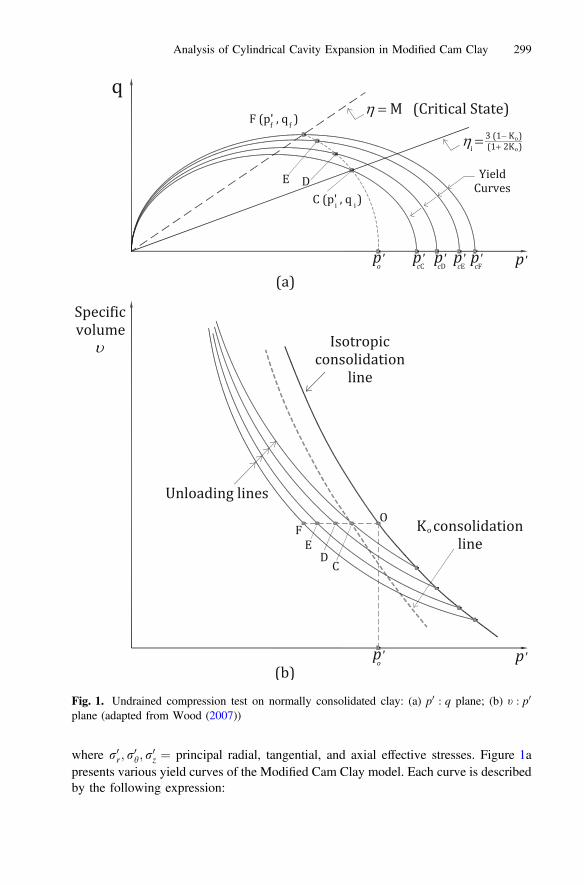
0z ¼ principal radial, tangential, and axial effective stresses. Figure 1a
presents various yield curves of the Modified Cam Clay model. Each curve is describedby the following expression:
Fig. 1. Undrained compression test on normally consolidated clay: (a) p0 : q plane; (b) t : p0
plane (adapted from Wood (2007))
Analysis of Cylindrical Cavity Expansion in Modified Cam Clay 299

q ¼ p0M p0c=p0� �� 1
� �1=2 ð2Þ
where M ¼ q=p0 at critical state ¼ 6sin/0= 3� sin/0ð Þ, with /0 ¼ friction angle andp0c ¼ hardening parameter. The latter parameter controls the size of the yield locus. Aneffective stress path (ESP) followed by a Ko normally consolidated specimen in anundrained compression test is also reported in Fig. 1a. The ESP is described by theexpression
q ¼ p0 M2 þ g2i� �
p0i=p0� �1=K�M2
h i1=2ð3aÞ
where
gi ¼ qi=p0i ¼ 3 1� Koð Þ= 1þ 2Koð Þ;qi ¼ r0zi � r0ri ¼ r0zi � r0hi ¼ 1� Koð Þr0zi;p0i ¼ r0ri þ r0hi þ r0zi
� �=3 ¼ 1þ 2Koð Þr0zi=3;
r0ri ¼ r0hi; r0zi ¼ initial horizontal and vertical effective stresses, respectively,
Ko ¼ r0ri=r0zi ¼ r0hi=r
0zi ¼ in situ coefficient of lateral earth pressure at rest,
K ¼ k� jð Þ=k;k ¼ slope of t : ln p0 line in loading (Fig. 1b),j ¼ slope of t : ln p0 line in unloading (Fig. 1b),t ¼ 1þ e ¼ specific volume, ande ¼ void ratio:
The ESP may also be described by the following equation:
q ¼ p0M p0o=p0� �1=K�1
h i1=2ð3bÞ
where p0o ¼ value of p0 for q ¼ 0, as shown in Fig. 1a. The ESP of the Ko normally
consolidated specimen begins at point C p0i; qi� �
and ends at point F p0f ; qf� �
on the
critical state line, whose coordinates are p0f ¼ 2�Kp0o and qf ¼ Mp0f ¼ 2�KMp0o (Wood
2007). The undrained shear strength Su is equal to qf /ffiffiffi3
p. As the expansion occurs
under undrained conditions, the specific volume t remains constant along the ESP, asshown in Fig. 1b, and each point on the stress path lies on a new yield locus. The testthus moves across progressive higher yield loci, which are associated with expansion ofthe yield locus and with decrease of the mean effective stress p0 for the normallyconsolidated specimen.
2.2 Modified Cam Clay Stress-Strain Relationships
Silvestri and Abou-Samra (2012) showed that the incremental elastic-plastic relation-ships of the Modified Cam Clay model in undrained shearing are given by:
300 V. Silvestri and C. Tabib
dr0r ¼ 2G0der þ dp0 1þ 6G0j r0r � p0� �
tM2p0 2p0 � p0c� �
" #ð4aÞ
dr0h ¼ 2G0deh þ dp0 1þ 6G0j r0h � p0� �
tM2p0 2p0 � p0c� �
" #ð4bÞ
dr0z ¼ 2G0dez þ dp0 1þ 6G0j r0z � p0� �
tM2p0 2p0 � p0c� �
" #ð4cÞ
where der; deh; dez = incremental radial, tangential, and axial natural strains. However,as dez ¼ 0 in plane strain and der þ deh ¼ 0 in undrained shearing, then Eqs. 4a–4cbecome:
dr0r ¼ �2G0deh þ dp0 1þ 6G0j r0r � p0� �
tM2p0 2p0 � p0c
� �" #
ð5aÞ
dr0h ¼ 2G0deh þ dp0 1þ 6G0j r0h � p0� �
tM2p0 2p0 � p0c� �
" #ð5bÞ
dr0z ¼ dp0 1þ 6G0j r0z � p0� �
tM2p0 2p0 � p0c
� �" #
ð5cÞ
The shear modulus G0 and the hardening parameter p0c are given by (See, for example,Wood 2007):
G0 ¼ 32
1� 2v0ð Þ1þ v0ð Þ K ¼ 3
21� 2v0ð Þ1þ v0ð Þ
tp0
jð6Þ
and
p0c ¼ p0 p0o=p0� �1=K ð7Þ
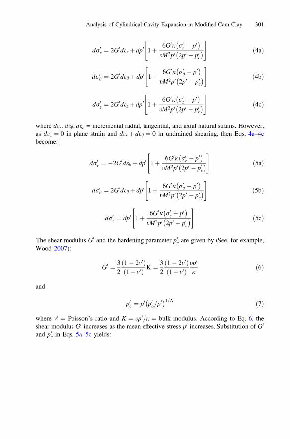
where v0 ¼ Poisson’s ratio and K ¼ tp0=j ¼ bulk modulus. According to Eq. 6, theshear modulus G0 increases as the mean effective stress p0 increases. Substitution of G0
and p0c in Eqs. 5a–5c yields:
Analysis of Cylindrical Cavity Expansion in Modified Cam Clay 301
dr0r ¼ �31� 2v0ð Þ1þ v0ð Þ
tp0
jdeh þ dp0 1þ 9
M2
1� 2v0ð Þ1þ v0ð Þ
r0r � p0� �
2� p0o=p0� �1=K� �
p0
24
35 ð8aÞ
dr0h ¼ 31� 2v0ð Þ1þ v0ð Þ
tp0
jdeh þ dp0 1þ 9
M2
1� 2v0ð Þ1þ v0ð Þ
r0h � p0� �
2� p0o=p0� �1=K� �
p0
24
35 ð8bÞ
dr0z ¼ dp0 1þ 9M2
1� 2v0ð Þ1þ v0ð Þ
r0z � p0� �
2� p0o=p0� �1=K� �
p0
24
35 ð8cÞ
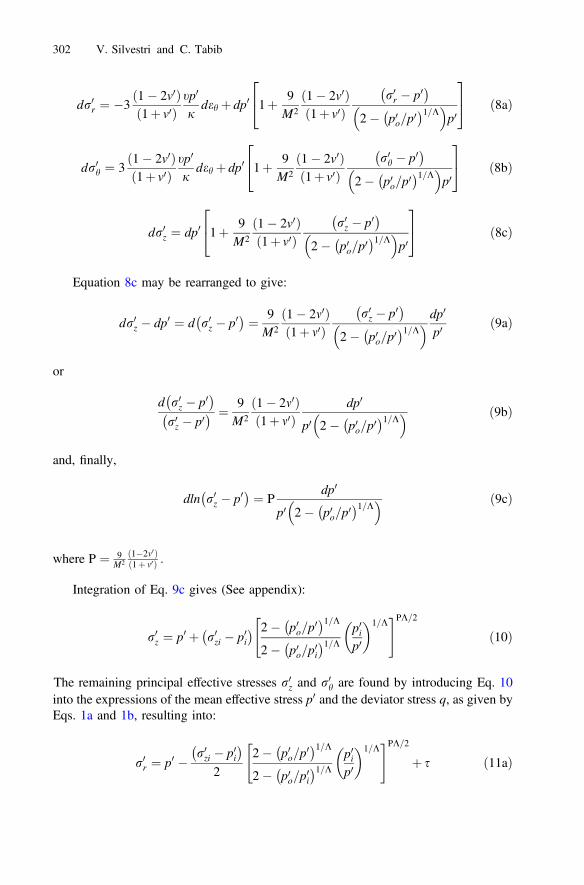
Equation 8c may be rearranged to give:
dr0z � dp0 ¼ d r0z � p0� � ¼ 9
M2
1� 2m0ð Þ1þ m0ð Þ
r0z � p0� �
2� p0o=p0� �1=K� � dp0
p0ð9aÞ
or
d r0z � p0� �r0z � p0� � ¼ 9
M2
1� 2m0ð Þ1þ m0ð Þ
dp0
p0 2� p0o=p0� �1=K� � ð9bÞ
and, finally,
dln r0z � p0� � ¼ P
dp0
p0 2� p0o=p0� �1=K� � ð9cÞ
where P ¼ 9M2
1�2m0ð Þ1þ m0ð Þ :
Integration of Eq. 9c gives (See appendix):
r0z ¼ p0 þ r0zi � p0i� � 2� p0o=p
0� �1=K2� p0o=p
0i
� �1=K p0ip0
1=K" #PK=2
ð10Þ
The remaining principal effective stresses r0z and r0h are found by introducing Eq. 10into the expressions of the mean effective stress p0 and the deviator stress q, as given byEqs. 1a and 1b, resulting into:
r0r ¼ p0 � r0zi � p0i� �
22� p0o=p
0� �1=K2� p0o=p
0i
� �1=K p0ip0
1=K" #PK=2
þ s ð11aÞ
302 V. Silvestri and C. Tabib

and
r0h ¼ p0 � r0zi � p0i� �
22� p0o=p
0� �1=K2� p0o=p
0i
� �1=K p0ip0
1=K" #PK=2
�s ð11bÞ
where the shear stress s in the horizontal plane (r : h) is equal to r0r � r
0h
� �=2 and is
given by:
s ¼ 12
43q2 � 3 r0zi � p0i
� �2 2� p0o=p0� �1=K
2� p0o=p
0i
� �1=K p0ip0
1=K" #PK
8<:
9=;
1=2
ð12Þ
The natural shear strain c is found by integration of the incremental shear straindc ¼ der � dehj j ¼ 2deh, which is determined from Eqs. 5a and 5b, that is, from
dc ¼ dsG0 �
6jsdp0
tM2p0 2p0 � p0c
� � ð13aÞ
or
dc ¼ 23
1þ v0ð Þ1� 2v0ð Þ
jdstp0
� 6jsdp0
tM2p0 2p0 � p0c� � ð13bÞ
where G0 is given by Eq. 6. Integration of Eq. 13b gives:
c ¼ 23j 1þ v0ð Þt 1� 2v0ð Þ
Zs
0
dsp0
� 6jtM2
Zp0
p0i
sdp0
p0 2p0 � p0c� � ð14Þ
where the hardening parameter p0c ¼ p0 p0o=p0i
� �1=Kfrom Eq. 7. It is apparent that the
shear strain c in Eq. 14 must be evaluated numerically due to the complex nature of theexpression of the shear stress s from Eq. 12.
Computations of total radial stress and pore pressure were carried out following thesame approach of Silvestri and Abou-Samra (2012). For completeness, their expres-sions are briefly repeated herein.
The total radial stress rr acting in the clay around the expanding cylindrical cavityis given by (Yu 2000; Silvestri and Abou-Samra 2012):
rr ¼ Zc
0
sdcec � 1
þ rri ð15aÞ
Analysis of Cylindrical Cavity Expansion in Modified Cam Clay 303
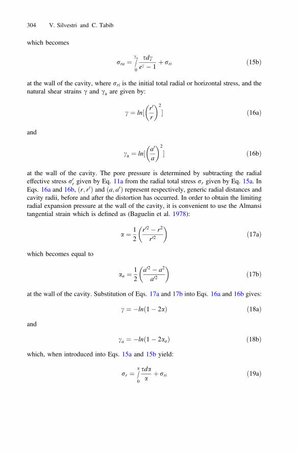
which becomes
rra ¼ Zca0
sdcec � 1
þ rri ð15bÞ
at the wall of the cavity, where rri is the initial total radial or horizontal stress, and thenatural shear strains c and ca are given by:
c ¼ ln½ r0
r
2
� ð16aÞ
and
ca ¼ ln½ a0
a
2
� ð16bÞ
at the wall of the cavity. The pore pressure is determined by subtracting the radialeffective stress r0r given by Eq. 11a from the radial total stress rr given by Eq. 15a. InEqs. 16a and 16b, r; r0ð Þ and a; a0ð Þ represent respectively, generic radial distances andcavity radii, before and after the distortion has occurred. In order to obtain the limitingradial expansion pressure at the wall of the cavity, it is convenient to use the Almansitangential strain which is defined as (Baguelin et al. 1978):
a ¼ 12
r02 � r2
r02
ð17aÞ
which becomes equal to
aa ¼ 12
a02 � a2
a02
ð17bÞ
at the wall of the cavity. Substitution of Eqs. 17a and 17b into Eqs. 16a and 16b gives:
c ¼ �ln 1� 2að Þ ð18aÞ
and
ca ¼ �ln 1� 2aað Þ ð18bÞ
which, when introduced into Eqs. 15a and 15b yield:
rr ¼ Za
0
sdaa
þ rri ð19aÞ
304 V. Silvestri and C. Tabib

and
rra ¼ Zaa0
sdaa
þ rri ð19bÞ
at the wall of the cavity, as also obtained by Baguelin et al. (1978). As mentionedabove, the Almansi tangential strain was introduced for facilitating the determination ofthe limiting radial expansion pressure. Indeed, consideration of the upper limit of theintegral in Eq. 15b indicates that ca must be equal to infinity for the radial pressure toreach the limiting expansion condition. Such a calculation may involve considerablecomputational problems. However, because Eq. 18b shows that ca ¼ 1 is reached foraa ¼ 0:5, then it becomes relatively easy to carry on the integration process in Eq. 19bup to aa ¼ 0:5 without experiencing any computational difficulties. This shows thesuperiority of the Almansi tangential strain over the natural strain in extending theintegration process to infinity. There is also an additional advantage. In effect, inseveral software programs involving either finite elements or finite differences, it isoften assumed that critical state is reached when the cavity radius has doubled in size,that is, when a0 ¼ 2a in order to avoid numerical difficulties. As this condition cor-responds to aa ¼ 0:375 from Eq. 17b or to ca ¼ 1:386 from Eq. 18b, it is apparent thatthe limiting state of aa ¼ 0:5 is still far away and that by setting aa ¼ 0:375 can onlyresult in approximate limiting values.
3 Application
Before discussing in detail the application of the various theoretical expressions derivedpreviously to the benchmark case presented below, it should be mentioned that theModified Cam Clay model is known to give reasonable results only for isotropicallynormally consolidated clays (See, for example, Wood 2007). If either the initial stressstate or the clay fabric, or both, are anisotropic, or if the soil is overconsolidated, bettermodels should be resorted to, for example, such as the anisotropic Modified Cam Claymodel (Dafalias 1987; Dafalias et al. 2002, 2006) or the Banerjee model (Banerjee andYousif 1986; Banerjee et al. 1988). These two models have the advantage over moresophisticated and complex models that they can account for both inherent and inducedanisotropy with relatively few model parameters. It is the authors’ intention to applyone of these models to the problem at hand in the near future.
However, as the principal aim of the present study was to obtain the exact solutionof the principal effective stresses generated around a cylindrical cavity in ModifiedCam Clay under plane strain and undrained conditions, computations were carried outassuming that the Modified Cam Clay model could also be applied to a Ko normallyconsolidated clay.
The theoretical relationships derived previously will be applied to the simulation ofa plane strain undrained expansion of a cylindrical cavity in Ko normally consolidatedremoulded Boston Blue Clay modelled as Modified Cam Clay. The properties ofthe clay are the following (Randolph et al. 1979): OCR = 1, Ko ¼ 0:55, t ¼ 2:16;
Analysis of Cylindrical Cavity Expansion in Modified Cam Clay 305
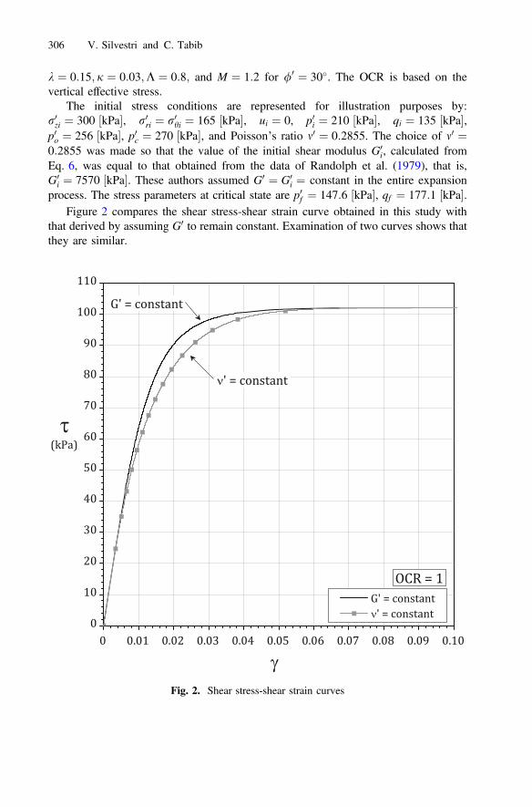
k ¼ 0:15; j ¼ 0:03;K ¼ 0:8; and M ¼ 1:2 for /0 ¼ 30�. The OCR is based on thevertical effective stress.
The initial stress conditions are represented for illustration purposes by:r0zi ¼ 300 kPa½ �, r0ri ¼ r0hi ¼ 165 kPa½ �, ui ¼ 0, p0i ¼ 210 kPa½ �, qi ¼ 135 kPa½ �,p0o ¼ 256 kPa½ �, p0c ¼ 270 kPa½ �, and Poisson’s ratio m0 ¼ 0:2855. The choice of m0 ¼0:2855 was made so that the value of the initial shear modulus G0
i, calculated fromEq. 6, was equal to that obtained from the data of Randolph et al. (1979), that is,G0
i ¼ 7570 kPa½ �. These authors assumed G0 ¼ G0i ¼ constant in the entire expansion
process. The stress parameters at critical state are p0f ¼ 147:6 kPa½ �, qf ¼ 177:1 kPa½ �.Figure 2 compares the shear stress-shear strain curve obtained in this study with
that derived by assuming G0 to remain constant. Examination of two curves shows thatthey are similar.
Fig. 2. Shear stress-shear strain curves
306 V. Silvestri and C. Tabib
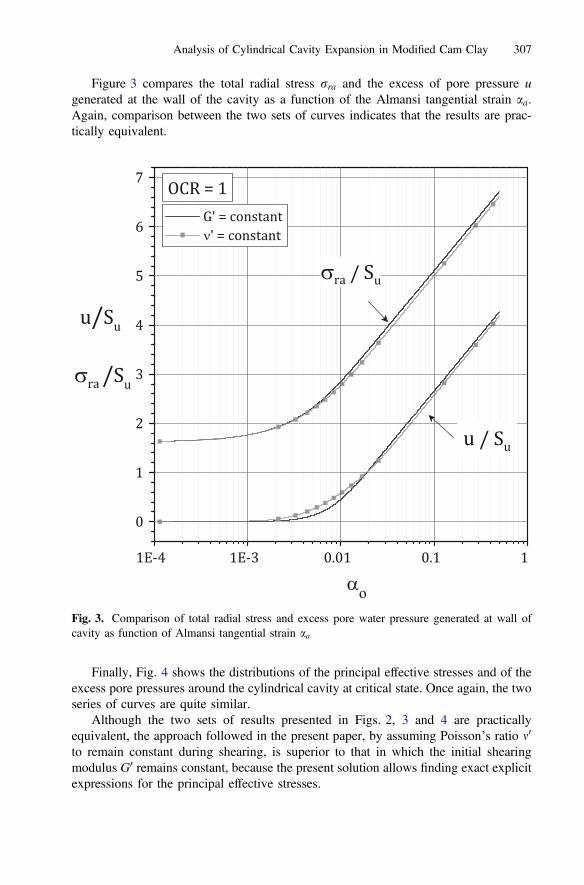
Figure 3 compares the total radial stress rra and the excess of pore pressure ugenerated at the wall of the cavity as a function of the Almansi tangential strain aa.Again, comparison between the two sets of curves indicates that the results are prac-tically equivalent.
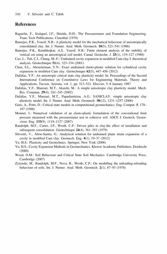
Finally, Fig. 4 shows the distributions of the principal effective stresses and of theexcess pore pressures around the cylindrical cavity at critical state. Once again, the twoseries of curves are quite similar.
Although the two sets of results presented in Figs. 2, 3 and 4 are practicallyequivalent, the approach followed in the present paper, by assuming Poisson’s ratio m0
to remain constant during shearing, is superior to that in which the initial shearingmodulus G0 remains constant, because the present solution allows finding exact explicitexpressions for the principal effective stresses.
Fig. 3. Comparison of total radial stress and excess pore water pressure generated at wall ofcavity as function of Almansi tangential strain aa
Analysis of Cylindrical Cavity Expansion in Modified Cam Clay 307

4 Conclusions
On the basis of the results reported in this paper, the following main conclusions aredrawn:
1. The assumption of constant Poisson’s ratio allows obtaining explicit expressions forthe principal effective stresses generated around an expanding cylindrical cavity inModified Cam Clay.
2. The theoretical relationships are applied to the simulation of an expanding cylin-drical cavity in Ko normally consolidated remoulded Boston Blue Clay. The results,which are compared with those obtained by assuming that the shear modulus G0
remains constant during the expansion, show that the two approaches are quitesimilar.
Acknowledgements. The author expresses his gratitude to the Natural Sciences and Engi-neering Research Council of Canada for the financial support received in this study.
Fig. 4. Distributions of principal effective stresses and excess pore water pressures aroundcylindrical cavity at critical state
308 V. Silvestri and C. Tabib
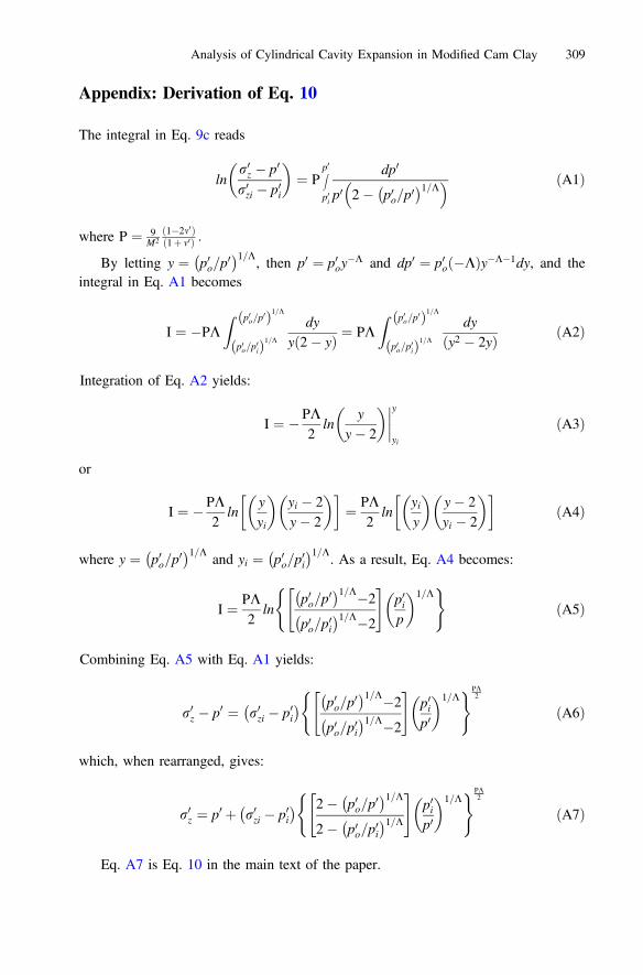
Appendix: Derivation of Eq. 10
The integral in Eq. 9c reads
lnr0z � p0
r0zi � p0i
¼ P
Zp0
p0i
dp0
p0 2� p0o=p0� �1=K� � ðA1Þ
where P ¼ 9M2
1�2m0ð Þ1þ m0ð Þ :
By letting y ¼ p0o=p0� �1=K
, then p0 ¼ p0oy�K and dp0 ¼ p0o �Kð Þy�K�1dy, and the
integral in Eq. A1 becomes
I ¼ �PKZ p0o=p
0ð Þ1=K
p0o=p0ið Þ1=K
dyy 2� yð Þ ¼ PK
Z p0o=p0ð Þ1=K
p0o=p0ið Þ1=K
dyy2 � 2yð Þ ðA2Þ
Integration of Eq. A2 yields:
I ¼ � PK2
lny
y� 2
����y
yi
ðA3Þ
or
I ¼ � PK2
lnyyi
yi � 2y� 2
� ¼ PK
2ln
yiy
y� 2yi � 2
� ðA4Þ
where y ¼ p0o=p0� �1=K
and yi ¼ p0o=p0i
� �1=K. As a result, Eq. A4 becomes:
I ¼ PK2
lnp0o=p
0� �1=K�2
p0o=p0i
� �1=K�2
" #p0ip
1=K( )
ðA5Þ
Combining Eq. A5 with Eq. A1 yields:
r0z � p0 ¼ r0zi � p0i� � p0o=p
0� �1=K�2
p0o=p0i
� �1=K�2
" #p0ip0
1=K( )PK
2
ðA6Þ
which, when rearranged, gives:
r0z ¼ p0 þ r0zi � p0i� � 2� p0o=p
0� �1=K2� p0o=p
0i
� �1=K" #
p0ip0
1=K( )PK
2
ðA7Þ
Eq. A7 is Eq. 10 in the main text of the paper.
Analysis of Cylindrical Cavity Expansion in Modified Cam Clay 309
References
Baguelin, F., Jézéquel, J.F., Shields, D.H.: The Pressuremeter and Foundation Engineering.Trans Tech Publications, Clausthal (1978)
Banerjee, P.K., Yousif, N.B.: A plasticity model for the mechanical behaviour of anisotropicallyconsolidated clay. Int. J. Numer. Anal. Meth. Geomech. 10(5), 521–541 (1986)
Banerjee, P.K., Kumbhojkar, A.S., Yousif, N.B.: Finite element analysis of the stability ofvertical cut using an anisotropical soil model. Canad. Geotechn. J. 25(1), 119–127 (1988)
Cao, L., Teh, C.I., Chang, M.-F.: Undrained cavity expansion in modified Cam clay I: theoreticalanalysis. Géotechnique 51(4), 323–334 (2001)
Chen, S.L., Abousleiman, Y.N.: Exact undrained elasto-plastic solution for cylindrical cavityexpansion in modified Cam clay. Géotechnique 62(5), 447–456 (2012)
Dafalias, Y.F.: An anisotropic critical state clay plasticity model. In: Proceedings of the SecondInternational Conference on Constitutive Laws for Engineering Materials. Theory andApplications, Tucson, Arizona, vol. 1, pp. 513–521. Elsevier, 5–8 January 1987
Dafalias, Y.F., Manzari, M.T., Akaishi, M.: A simple anisotropic clay plasticity model. Mech.Res. Commun. 29(4), 241–245 (2002)
Dafalias, Y.F., Manzari, M.T., Papadimitriou, A.G.: SANICLAY: simple anisotropic clayplasticity model. Int. J. Numer. Anal. Meth. Geomech. 30(12), 1231–1257 (2006)
Gens, A., Potts, D.: Critical state models in computational geomechanics. Eng. Comput. 5, 178–197 (1988)
Monnet, J.: Numerical validation of an elasto-plastic formulation of the conventional limitpressure measured with the pressuremeter test in cohesive soil. ASCE J. Geotech. Geoen-viron. Eng. 133(9), 1119–1127 (2007)
Randolph, M.F., Carter, J.P., Wroth, C.P.: Driven piles in clay-the effect of installation andsubsequent consolidation. Géotechnique 24(4), 361–393 (1979)
Silvestri, V., Abou-Samra, G.: Analytical solution for undrained plane strain expansion of acavity in modified Cam clay. Geomech. Eng. 4(1), 19–37 (2012)
Yu, H.S.: Plasticity and Geotechnics. Springer, New York (2006)Yu, H.S.: Cavity Expansion Methods in Geomechanics. Kluwer Academic Publishers, Dordrecht
(2000)Wood, D.M.: Soil Behaviour and Critical State Soil Mechanics. Cambridge University Press,
Cambridge (2007)Zytynski, M., Randolph, M.F., Nova, R., Wroth, C.P.: On modelling the unloading-reloading
behaviour of soils. Int. J. Numer. Anal. Meth. Geomech. 2(1), 87–93 (1978)
310 V. Silvestri and C. Tabib