ANALYSIS OF BRIDGE GIRDER WITH BEAM AND …€¦ · s calculated as per irc :6-2000 G STAAD PRO...
10
http://www.iaeme.com/IJCIET/index.asp 337 [email protected] International Journal of Civil Engineering and Technology (IJCIET) Volume 7, Issue 5, September-October 2016, pp. 337–346, Article ID: IJCIET_07_05_038 Available online at http://www.iaeme.com/IJCIET/issues.asp?JType=IJCIET&VType=7&IType=5 ISSN Print: 0976-6308 and ISSN Online: 0976-6316 © IAEME Publication ANALYSIS OF BRIDGE GIRDER WITH BEAM AND WITHOUT BEAM Kalpana Mohan Assistant Professor, Department of Civil Engineering, Saveetha School of Engineering, Saveetha University, Thandalam, Chennai. S. P. Vijay Kumar Assistant Professor, Department of Civil Engineering, Saveetha School of Engineering, Saveetha University, Thandalam, Chennai. ABSTRACT Bridge girder material, size, shape and selection are based on engineering and economic criteria. Steel concrete composite construction has gained wide acceptance as an alternative to pure steel and pure concrete construction, there is no need for formwork because the steel beam is able to sustain the self-weight of steel and concrete with few temporary props.In this paper, we present analysis and results of steel and steel reinforce bridge girders, based on STAAD Pro analysis and manual analysis.8 combinations of bridge girders as given below are taken and compared: RCC 0.5*1 WITH OUT BEAM RCC 0.5*1 WITH BEAM RCC 0.4*0.8 WITH OUT BEAM RCC 0.4*0.8 WITH BEAM RCC I SHAPE WITH OUT BEAM flange size 0.9m x 0.15m and web size is 0.3m x 0.3m RCC I SHAPE WITH BEAM STEEL I SHAPE WITH OUT BEAM flange size 0.9m x 0.15m and web size is 0.3m x 0.3m total height of i girder is 0.6m STEEL I SHAPE WITH BEAM The analysis was conducted between steel girders and reinforced concrete bridge girders. Based on the design calculations, effect of each girder with respect to shear, bending moment, dead load, live load, deflection and most importantly cost of each combination is analysed. Keywords: Bridge girder, beam , STAAD Pro etc. Cite this Article: Kalpana Mohan and S. P. Vijaykumar, Analysis of Bridge Girder with Beam and without Beam. International Journal of Civil Engineering and Technology, 7(5), 2016, pp.337–346. http://www.iaeme.com/IJCIET/issues.asp?JType=IJCIET&VType=7&IType=5
Transcript of ANALYSIS OF BRIDGE GIRDER WITH BEAM AND …€¦ · s calculated as per irc :6-2000 G STAAD PRO...

http://www.iaeme.com/IJCIET/index.asp 337 [email protected]
International Journal of Civil Engineering and Technology (IJCIET) Volume 7, Issue 5, September-October 2016, pp. 337–346, Article ID: IJCIET_07_05_038
Available online at http://www.iaeme.com/IJCIET/issues.asp?JType=IJCIET&VType=7&IType=5
ISSN Print: 0976-6308 and ISSN Online: 0976-6316
© IAEME Publication
ANALYSIS OF BRIDGE GIRDER WITH BEAM AND
WITHOUT BEAM
Kalpana Mohan
Assistant Professor, Department of Civil Engineering, Saveetha School of Engineering,
Saveetha University, Thandalam, Chennai.
S. P. Vijay Kumar
Assistant Professor, Department of Civil Engineering, Saveetha School of Engineering,
Saveetha University, Thandalam, Chennai.
ABSTRACT
Bridge girder material, size, shape and selection are based on engineering and economic
criteria. Steel concrete composite construction has gained wide acceptance as an alternative to
pure steel and pure concrete construction, there is no need for formwork because the steel beam is
able to sustain the self-weight of steel and concrete with few temporary props.In this paper, we
present analysis and results of steel and steel reinforce bridge girders, based on STAAD Pro
analysis and manual analysis.8 combinations of bridge girders as given below are taken and
compared:
RCC 0.5*1 WITH OUT BEAM
RCC 0.5*1 WITH BEAM
RCC 0.4*0.8 WITH OUT BEAM
RCC 0.4*0.8 WITH BEAM
RCC I SHAPE WITH OUT BEAM flange size 0.9m x 0.15m and web size is 0.3m x 0.3m
RCC I SHAPE WITH BEAM
STEEL I SHAPE WITH OUT BEAM flange size 0.9m x 0.15m and web size is 0.3m x 0.3m total
height of i girder is 0.6m
STEEL I SHAPE WITH BEAM
The analysis was conducted between steel girders and reinforced concrete bridge girders.
Based on the design calculations, effect of each girder with respect to shear, bending moment, dead
load, live load, deflection and most importantly cost of each combination is analysed.
Keywords: Bridge girder, beam , STAAD Pro etc.
Cite this Article: Kalpana Mohan and S. P. Vijaykumar, Analysis of Bridge Girder with Beam and
without Beam. International Journal of Civil Engineering and Technology, 7(5), 2016, pp.337–346.
http://www.iaeme.com/IJCIET/issues.asp?JType=IJCIET&VType=7&IType=5

Analysis of Bridge Girder with Beam and without Beam
http://www.iaeme.com/IJCIET/index.asp 338 [email protected]
1. INTRODUCTION
1.1. Bridge
A Bridge is a structure built to span physical obstacles without closing the way underneath such as a body
of water, valley, or road, for the purpose of providing passage over the obstacle. There are many different
designs that each serve a particular purpose and apply to different situations. Designs of bridges vary
depending on the function of the bridge, the nature of the terrain where the bridge is constructed and
anchored, the material used to make it, and the funds available to build it.
Types of bridges:
• Girder bridges
• Arc bridges
• Truss bridges
• Suspended bridges
• Prestressed bridges
• Rigid Frame Bridges
2. LITERATURE REVIEW
Various journals and thesis were refereed and the design aspects were studied. Variable parameters such as
Depth of web, thickness of web, width of flange and span of bridges are the variable parameters considered
during the design of plate Girder Bridge. Plate girder bridge is designed as per the Limit state method
using the IS 800:2007, IRC: 24-2000 and analysed bySAP-2000. Basically the Indian standards are derived
from the British Standards. With depth of web to thickness of Web ratio remains the same, flange area
varies as per the variation of span.
The behaviour of concrete bridge decks reinforced with newly developed high-performance (HP) steel
t is characterized by its high strength and enhanced corrosion-resistance in comparison with conventional
ASTM A6JS-06 Grade 60 steel. A nonlinear finite element model was used to predict the mode of failure
and failure loads. Specially-designed specimens were studied to know the effect of bending of HP steel
bars on their tensile strength.
3. METHODOLOGY
3.1. Girder Bridge
A girder bridge, in general, is a bridge that uses girders as the means of supporting the deck. A bridge
consists of three parts: the foundation (abutments and piers), the superstructure (girder, truss, or arch), and
the deck. A girder bridge is very likely the most commonly built and utilized bridge in the world. Its basic
design, in the most simplified form, can be compared to a log ranging from one side to the other across a
river or creek. In modern girder steel bridges, the two most common shapes are plate girders and box-
girders. The term "girder" is often used interchangeably with "beam" in reference to bridge design.
3.2. Different Types of Girder in Bridge
According to shape:
Box Shape, I Shape, T Shape, C Shape
According to length of bridge:
Culvert bridge(less than 6 m) , Minor bridge(less than 6 m-60m), Major bridge(more than 60 m), Long
span bridge(more than 120 m)

http://www.iaeme.com/IJCIET/index.asp
3.3. Input of Bridge
• Length of bridge =15m
• Width of carriage bridge=8.550m
• Width of footpath = 1.5m
• Total width =11.550m
• Thickness of deck slab =0.225m
• Thickness of wearing coat=0.075m
• Number of girders=4
• Spacing of main girder =2.850m
3.4. Unit Weights & Loads
• reinforced cement concrete =40kn/m3
• wearing coat = 22kn/m3
• structural steel =78.5 kn/m3
• steel used fe 415
• irc class aa& class a wheeled load
• if span 7.5m to 30m
• where p’=400 or500kg/m2 from sub class 209.1 irc6
• formula cal. for ll for footpath =4.5kn/m
4. STEP 1: ANALYSIS OF BRIDGES USIN
4.1. Rectangular Girder size 0.5 x 1 m with
It is similar to rectangular 0.5 x 1m without beam. Beams are placed at starting point of bridge and ending
point of bridge that is zero meter and 15 meter
beam sizes 0.25 * 0.5m. Property of cross beam is recta
given in bridge as given before for without beam
Figure 3.3 Deflection of Rectangular girder s
Kalpana Mohan and S. P. Vijaykumar
iaeme.com/IJCIET/index.asp 339
Width of carriage bridge=8.550m
=0.225m
Thickness of wearing coat=0.075m
Spacing of main girder =2.850m
reinforced cement concrete =40kn/m3
irc class aa& class a wheeled loads calculated as per irc :6-2000
where p’=400 or500kg/m2 from sub class 209.1 irc6
formula cal. for ll for footpath =4.5kn/m
YSIS OF BRIDGES USING STAAD PRO
ize 0.5 x 1 m with Beam (1 way)
lar to rectangular 0.5 x 1m without beam. Beams are placed at starting point of bridge and ending
point of bridge that is zero meter and 15 meter. In Rectangular 0.5 * 1m Sizes Girder having the cross
Property of cross beam is rectangular and material is concrete
given in bridge as given before for without beam
Deflection of Rectangular girder size 0.5 x 1 m with beam (1 way)
lar to rectangular 0.5 x 1m without beam. Beams are placed at starting point of bridge and ending
In Rectangular 0.5 * 1m Sizes Girder having the cross
ngular and material is concrete. Similar load are
ize 0.5 x 1 m with beam (1 way)

Analysis of Bridge Girder with Beam and without Beam
http://www.iaeme.com/IJCIET/index.asp
Figure 3.4 Bending moment of Rectangular girder size 0.5 x 1 m with beam (1 w
Figure 3.5 Shear force of Rectangular girder size 0.5 x 1 m with beam (1 way)
4.2. Rectangular Girder size 0.4 x 0.8 m without
It is similar to Rectangular girder size of 0.5 x 1 m withou
changed.Width of the girder is 0.4 meter and de
combination is similar. Here also 25
moment and Shear force is changed compare with the rect 0.5 x 1m
Figure 3.6 4 displacement of Rectangular girder size 0.4 x 0.8 m without beam
Analysis of Bridge Girder with Beam and without Beam
http://www.iaeme.com/IJCIET/index.asp 340
Bending moment of Rectangular girder size 0.5 x 1 m with beam (1 w
Shear force of Rectangular girder size 0.5 x 1 m with beam (1 way)
r size 0.4 x 0.8 m without Beam
similar to Rectangular girder size of 0.5 x 1 m without beam. Here only gi
he girder is 0.4 meter and depth of the girder is 0.8 meters.
Here also 250 load combination is generated. Values of Deflection, bending
moment and Shear force is changed compare with the rect 0.5 x 1m.
displacement of Rectangular girder size 0.4 x 0.8 m without beam
Analysis of Bridge Girder with Beam and without Beam
Bending moment of Rectangular girder size 0.5 x 1 m with beam (1 way):
Shear force of Rectangular girder size 0.5 x 1 m with beam (1 way)
Here only girder size in y axis is
pth of the girder is 0.8 meters. Supports and vehicle load
Values of Deflection, bending
displacement of Rectangular girder size 0.4 x 0.8 m without beam
http://www.iaeme.com/IJCIET/index.asp
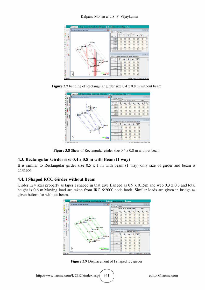
Figure 3.7 bending of Rectangular girder size 0.4 x 0.8 m without beam
`
Figure 3.8 Shear of Rectangular girder size 0.4 x 0.8 m without beam
4.3. Rectangular Girder size 0.4 x
It is similar to Rectangular girder size 0.5 x 1 m with beam (1 way) only size of girder and beam is
changed.
4.4. I Shaped RCC Girder without
Girder in y axis property as taper I shaped in t
height is 0.6 m.Moving load are taken from IRC 6:2000 code book
given before for without beam.
Fig
Kalpana Mohan and S. P. Vijaykumar
iaeme.com/IJCIET/index.asp 341
bending of Rectangular girder size 0.4 x 0.8 m without beam
Shear of Rectangular girder size 0.4 x 0.8 m without beam
e 0.4 x 0.8 m with Beam (1 way)
It is similar to Rectangular girder size 0.5 x 1 m with beam (1 way) only size of girder and beam is
irder without Beam
Girder in y axis property as taper I shaped in that give flanged as 0.9 x 0.15m
Moving load are taken from IRC 6:2000 code book. Similar load
Figure 3.9 Displacement of I shaped rcc girder
bending of Rectangular girder size 0.4 x 0.8 m without beam
Shear of Rectangular girder size 0.4 x 0.8 m without beam
It is similar to Rectangular girder size 0.5 x 1 m with beam (1 way) only size of girder and beam is
hat give flanged as 0.9 x 0.15m and web 0.3 x 0.3 and total
Similar loads are given in bridge as
Analysis of Bridge Girder with Beam and without Beam
http://www.iaeme.com/IJCIET/index.asp
Fig
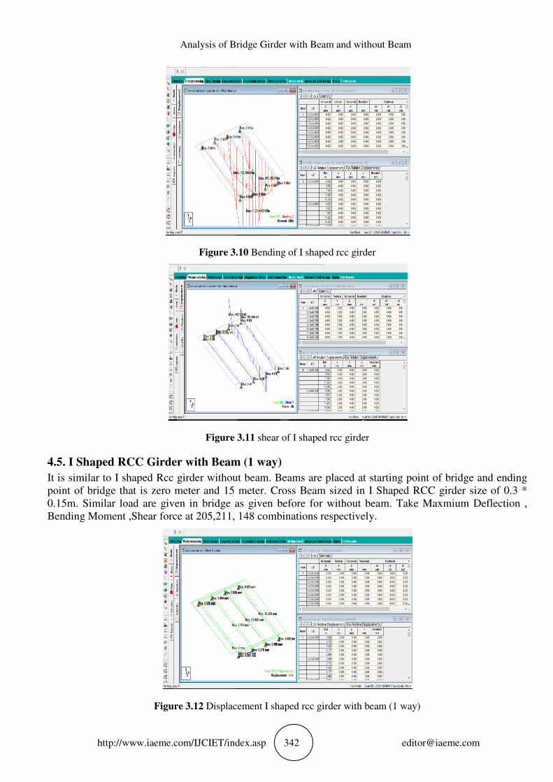
4.5. I Shaped RCC Girder with
It is similar to I shaped Rcc girder without beam. Beams are pl
point of bridge that is zero meter and 15 meter.
0.15m. Similar load are given in bridge a
Bending Moment ,Shear force at 205,211, 148 combinations respectively
Figure 3.12
Analysis of Bridge Girder with Beam and without Beam
http://www.iaeme.com/IJCIET/index.asp 342
Figure 3.10 Bending of I shaped rcc girder
Figure 3.11 shear of I shaped rcc girder
irder with Beam (1 way)
shaped Rcc girder without beam. Beams are placed at starting point of bridge and ending
hat is zero meter and 15 meter. Cross Beam sized in I Shape
Similar load are given in bridge as given before for without beam. Take Maxmium
Bending Moment ,Shear force at 205,211, 148 combinations respectively.
3.12 Displacement I shaped rcc girder with beam (1 w
Analysis of Bridge Girder with Beam and without Beam
aced at starting point of bridge and ending
Cross Beam sized in I Shaped RCC girder size of 0.3 *
Take Maxmium Deflection ,
Displacement I shaped rcc girder with beam (1 way)

http://www.iaeme.com/IJCIET/index.asp
Figure 3.13
Figure
4.6. I Shaped Steel Girder without
It similar to I shaped rcc girder only mat
taper I shaped select material as steel in staadpro.
girder. Take MaxmiumDeflection , Bending Moment ,Shear force at 205,211, 148 combinations
respectively.Values of deflection, bending mome
4.7. Shaped Steel Girder with
It is similar to I shaped rcc girder with beam (1 way)
5. RESULTS AND DISCUSSI
In this results and discussion the values for Deflection, Bending moment an
staad pro. Maximum Deflection o
combination number:211. Maximum Shear force oc
without beam and beam (one way) have approximately values
Because in 15 meter span we are giving cross
0 to 5m and 10 to 15m then deflection, bending moment, shear at 5 to 10m it
beam and beam
Kalpana Mohan and S. P. Vijaykumar
iaeme.com/IJCIET/index.asp 343
3.13 Bending I shaped rcc girder with beam (1 way)
ure 3.14 shear I shaped rcc girder with beam (1 way)
irder without Beam
It similar to I shaped rcc girder only material has been changed to steel. All modelling are same in
material as steel in staadpro.Moving load and loading everying is same to I
Take MaxmiumDeflection , Bending Moment ,Shear force at 205,211, 148 combinations
Values of deflection, bending moment and shear force is similar to I shaped rcc girder.
irder with Beam (1 way)
It is similar to I shaped rcc girder with beam (1 way).
RESULTS AND DISCUSSIONS
In this results and discussion the values for Deflection, Bending moment and Shear force is taken from the
Maximum Deflection occur at combination number 205. Maximum Bending moment oc
Maximum Shear force occur at combination number
way) have approximately values. All these values are in dynamic conditions
Because in 15 meter span we are giving cross beam at 5 m and 10m distance. When moving load is at from
0 to 5m and 10 to 15m then deflection, bending moment, shear at 5 to 10m it
Bending I shaped rcc girder with beam (1 way)
shear I shaped rcc girder with beam (1 way)
All modelling are same in property
Moving load and loading everying is same to I shaped rcc
Take MaxmiumDeflection , Bending Moment ,Shear force at 205,211, 148 combinations
to I shaped rcc girder.
d Shear force is taken from the
Maximum Bending moment occur at
cur at combination number:148. From the above values
All these values are in dynamic conditions.
When moving load is at from
0 to 5m and 10 to 15m then deflection, bending moment, shear at 5 to 10m it become lesser than without

Analysis of Bridge Girder with Beam and without Beam
http://www.iaeme.com/IJCIET/index.asp 344 [email protected]
Table 4.1 Values Form Staad pro Rectangular 0.5 X 1m sized girder
DEFLECTION
BENDING MOMENT
SHEAR
DESCRI
P
TION
COMB
INATIO
N
G
1
G2
G3
G4
G
1
G2
G3
G4
G
1
G2
G3
G4
WITHOU
T
0 3.10
9
32.51
4
14.34
6
0 130.09
9
1360 600.36
7
0 -
29.82
2
-
311.96
8
-
137.63
6
1 WAY 205 0 3.12
9
32.73
8
14.44
3
0 130.76 1370 603.51
0
0 -
29.82
2
-
311.97
9
-
137.63
6
WITHOU
T
211 0 3.11
7
32.60
4
14.38
4
0 132.88
0
1390 613.29
4
0 -
32.11
0
-
335.91
5
-
148.19
8
1 WAY 0 3.11
7
32.60
4
14.38
4
0 132.88
1
1390 613.29
4
0 -
32.11
0
-
335.91
5
-
148.19
8
WITHOU
T
148 0 2.17
5
22.77
5
10.03
9
0 83.814 876.82
1
386.83
3
0 -
42.35
7
-
443.12
4
-
195.49
6
1 WAY 0 2.17
5
22.77
5
10.03
9
0 83.814 876.82
1
386.83
3
0 -
42.35
7
-
443.12
4
-
195.49
6
Table 4.2 Values Form Staad pro Rectangular 0.4 X 0.8m sized girder
DESCRI
PTION
COM
BIN
ATION
DEFLECTION
BENDING MOMENT
SHEAR
C0N
CRETE
.8x0.4
G
1
G2 G3 G4 G
1
G2 G3 G4 G
1
G2 G3 G4
WITHOU
T
205 0 7.64 79.92
7
35.
260
0 130.760 137
0
603.510 0 -
29.82
2
-
311.97
9
-
137.36
8
1 WAY 0 7.640 79.92
7
35.
262
0 130.760 137
0
603.510 0 -
29.82
2
-
311.97
9
-
137.36
8
WITHOU
T
211 0 7.609 79.60 35.
118
0 132.880 139
0
613.294 0 -
32.11
0
-
335.95
5
-
148.19
8
1 WAY 0 7.609 79.60 35.
118
0 132.880 139
0
613.294 0 -
32.11
0
-
335.95
5
148.19
8
WITHOU
T
148 0 5.31
0
55.55
3
25.50
9
0 83.814 876.82
0
386.83
2
0 42.35
7
443.12
4
195.49
6
1 WAY 0 5.31
0
55.55
3
25.50
9
0 83.814 876.82
8
386.83
2
0 42.35
7
443.12
4
195.49
6

Kalpana Mohan and S. P. Vijaykumar
http://www.iaeme.com/IJCIET/index.asp 345 [email protected]
Table 4.3 Values Form Staad pro I shaped rcc girder
DES
CRI
PTION
CO
M
BIN
ATI
ON
DEFLECTION
BENDING MOMENT
SHEAR
I SHAPE G1 G2 G3 G4 G1 G2 G3 G4 G1 G2 G3 G4
WITH
OUT
205 0 8.78
1
91.85
8
40.5
26
0 130.
760
1370 603.5
09
0 -
29.82
2
-311.979 -
137.6
38
1 WAY 0 8.78
1
91.85
8
40.5
26
0 130.
762
1370 603.5
10
0 -
29.82
2
-311.976 -
137.6
38
WITHO
UT
211 0 8.74
5
91.48
2
40.3
60
0 132.
880
1390 613.2
93
0 -
32.11
0
-335.915 -
148.1
98
1 WAY 0 8.74
5
91.48
1
40.3
60
0 132.
882
1390 613.2
95
0 -
32.11
0
-335.915 -
148.1
98
WITH
OUT
0 6.10
3
63.84
6
28.1
67
0 83.8
15
876.8
20
386.8
33
0 42.35
7
443.124 195.4
96
1 WAY 148 0 6.10
3
63.84
5
28.1
67
0 83.8
15
876.8
18
386.8
33
0 42.35
7
443.124 195.4
96
• From the above values without beam and beam (one way) has approximately values
• Because in 15 meter span we are giving cross beam at 5 m and 10m distance.
When moving load is at from 0 to 5m and 10 to 15m then deflection , bending moment, shear at 5
to 10m it become lesser than without beam and beam.
Table 4.4 Values Form Staad pro I shaped steel girder
DES
CRI
PTIO
N
COM
BIN
ATIO
N
DEFLECTION BENDING MOMENT SHEAR
I
SHAP
E
STEEL
G
1
G2 G3 G4 G
1
G2 G3 G4 G
1
G2 G3 G4
WITH
OUT
205 0 0.93
0
9.73
2
4.29
3
0 130.76
1
1370 603.51
0
0 29.82
2
311.97
9
137.63
8
1
WAY
0 0.93
0
9.73
2
4.29
3
0 130.76
1
1370 603.51
0
0 29.82
2
311.97
9
137.63
8
WITH
OUT
211 0 0.92
6
9.69
2
4.27
6
0 132.88
1
1390 613.29
5
0 -
32.11
0
-335.91 -
148.19
8
1
WAY
0 0.92
6
9.69
2
4.27
6
0 132.88
1
1390 613.29
5
0 -
32.11
0
-335.92 -
148.19
8

Analysis of Bridge Girder with Beam and without Beam
http://www.iaeme.com/IJCIET/index.asp 346 [email protected]
WITH
OUT
148 0 0.64
7
6.76
4
2.98
4
0 83.814 876.82
2
386.83
3
0 42.35
7
443.12
4
195.49
6
1
WAY
0 0.64
7
6.76
4
2.98
4
0 83.814 876.82
1
386.83
3
0 42.35
7
434.75
4
195.49
6
6. CONCLUSION
Different arrangement of deck slab with girder was taken like, beams at edges taken as one way slab and
beams in between making deck slab two way. Having analysis the same for different cases. Bending
moment is higher in girder without beam and one way deck slab. Similarly, Rectangular shaped girder 0.4
x 0.8 m section has the same behaviour as mentioned above with different values. When comparing the
rectangular shaped girder 0.5 x 1m and 0.4 x 0.8 m, 0.4 x 0.8 m has more deflection which is a
disadvantage. In I section, deflection is more when compared to Rectangular 0.5 x 1 m section and Rcc 0.4
x 0.8 m section. And the I section steel girder has less deflection when compared to all types of girders.
With normal IRC loading bridge with girder spacing of 2.850m with span of 50 m the working load in
bending moment the order of 1600-1800 kN.m and shear force values comes in the order of 400-450 kN.
Where as per the staad pro terms 1390 & 440 it appears to be reasonable. From the above discussions, it
is concluded that composite steel section is good when compared to Rcc, because maintenance of
composite section is easy, construction time is faster and it also withstands high amount of load.
REFERENCE
[1] Construction of Maltekadi Railway Over Bridge On Mini Bypass Road Link Road MSH2 Nanded City
Navi Mumbai. Design of PSC I Girder. (SPAN 14.132M c/c Piers).
[2] Comparison of Design Standards for Steel Railway Bridges(Midhun B Sankar,Priya A Jacob)
[3] STEEL VERSUS STEEL-REINFORCED CONCRETE BRIDGES : By Arpad Horvath and Chris
Hendrickson
[4] Are Reinforced Concrete Girder Bridges More Economical Than Structural Steel Girder Bridges(Trevor
Haas:dept civil)
[5] Azmat Hussain, Saba Bashir and Saima Maqbool, Damage Detection in Bridges using Image
Processing. International Journal of Civil Engineering and Technology (IJCIET), 7(2),2016, pp.215–
225.
[6] Analysis of Plate Girder Bridge for Class-AA Loadings. Authors Mr.Shivraj D. Kopare ,Prof. K. S.
Upase
[7] Behavior of Concrete Bridge Decks Reinforced with High-Performance Steel(by Hatem M. Seliem,
Gregory Lucier, Sami H. Rizkalla; and Paul Zia)
[8] Patil M.B, Y.P.Pawar, S.S.Kadam, D.D.Mohite, S.V. Lale, C.M. Deshmukh and C.P. Pise, Analysis and
Comparative Study of Composite Bridge Girders. International Journal of Civil Engineering and
Technology (IJCIET), 7(3),2016, pp.354–364.
[9] T.R Jagadeesh, M.A.JAYARAM, Design of bridge structure 2009
[10] AmarjitAggarwal and A.K. Upadhyay , civil estimating, costing and valuation , 7 th edition, 2008
[11] S.C.Rangwala, K.S.Rangwala, civil estimating, costing and valuation ,17th edition, 2015
[12] Analysis & Design of 46m composite span for ROBs at Chainage km:8+981 & km 3+477. Simhapuri
Expressway Limited KMC – BSCPL (Consortium) , Banjara Hills, Hyderabad