Design Auto Adjust Sliding Surface Slope: Applied to Robot Manipulator
ANALYSIS OF AUTOMATED PLANNING APPLIED TO AN ASSEMBLY
AND DISASSEMBLY ROBOT SYSTEM
William Henrique Pereira Guimarães
Marco Vinícius Muniz Ferreira
João Paulo da Silva Fonseca
José Jean-Paul Zanlucchi de Souza Tavares
João Carlos Mendes Carvalho
Federal University of Uberlândia, Av. João Naves de Ávila, 2121 - Uberlândia, MG, Brazil.
[email protected], [email protected], [email protected], [email protected],
Abstract. Despite the high costs operations and the skilled labor lack, production processes require robots to improve
efficiency in assembly and disassembly lines. Historically, the robot programming is based on a set of predefined
sequential actions. In this case, devices and sensors are connected to the robot controller and the programming of the
shares is held directly by its internal software. This type of programming is usually fixed and has few or none flexibility
in handling concern, requiring the equipment reprogramming for new trajectories. On the other hand, several studies
have shown artificial intelligence techniques such as neural nets, genetic algorithms, automated planning as
enhancement proposals for practical systems. Automated planners emerged in 1971 in the STRIPS or “Stanford Research
Institute Problem Solver” with the first automatic solver problems. The automated planners’ development created a
standard formal language called PDDL or “Planning Domain Definition Language”. In 2008, itSIMPLE emerged as a
knowledge engineering tool used for modeling planning domains to several automated planners, in order to develop a
plan that meets the requirements of the project. This paper proposes the integration of automated planners with robots
control systems through itSIMPLE for assembly and disassembly processes. Such integration uses an especially device
made for this project, which is responsible for translating the sensors’ information into actual states. The automated
planners use these states and the generated plan is converted into a list of instructions (jobs) that is sent to the robot.
Finally, a comparison will be made with the traditional method of programming and robot's training.
Keywords: Products assembly and disassembly system, Automation Applied, Automated Planning, itSIMPLE,
Industrial Robot.
1. INTRODUCTION
In the sixteenth century, manufacturing systems were handmade, made in small shops, and the products were relatively
simple compared to today's standard. Over time, emergence mass production and factories were created, with many
workers in one place. With that, the craftwork techniques gave space to the production lines. The products become more
complex, as well as processed. Workers needed to specialize in tasks instead of overseeing the entire production. They
became responsible for a part of the job. More accurate planning and better coordination was needed so that it could
monitor the progress in factories. Today, production systems are necessary to sustain the life of civil society. The modern
manufacturing enterprises who manage them must consider the economic realities of the modern world. In the production
process, which seeks to improve the efficiency, proves to be increasingly required the use of automation such as robotics.
A robot is a device or group of devices, electromechanical and biomechanical able to perform work autonomously or
pre-programmed. Robots commonly perform tasks in poorly lit, dirty or dangerous for humans. Industrial robots used in
production lines are the most common robots, but there are other applications such as toxic waste treatment, underwater
and space exploration, surgery, mining, search and rescue, and locating landmines. The robots also appear in
entertainment and chores areas. Currently, the robot programming is based on a set of pre-defined sequential actions. This
programming is usually fixed and has few or none flexibility and other movements require the device reprogramming.
This generates high costs with hand labor (only qualified personnel perform the programming), loss in production due
the stops for reprogramming and the robot training with technical difficulties. Therefore, more complex programming
changes and software maintenance are restricted to the manufacturer. On the other hand, in a few years, several studies
have demonstrated artificial intelligence techniques such as neural networks, genetic algorithms, and automated planning
as improvement proposals for practical systems.
Almost 40 years ago began the developing of automated planning systems, but their implementation is still restricted
and often is a challenge due real applications languages differs significantly from automated planning ones (Vaquero,
ABCM Symposium Series in Mechatronics - Vol. 6 Copyright © 2014 by ABCM
Part I - International Congress Section IV - Robotics
588

2007). Since 1971, with the emergence of the STRIPS (Stanford Research Institute Problem Solver) (Fikes, Nilsson,
1971), based on logical systems are created to solve problems automatically. The concept of these systems is the existence
of a real system model describing the actions and rules for each object that composes a set of inputs (baseline) and a
desired state (final state). This model makes use of search algorithms applied with the model rules to find a path that starts
from the set of inputs and achieve the desired state.
While the automated planning presents a plan for a specific case in a restrict language called Planning Domain
Definition Language (PDDL) (Fox and Long, 2003), the real systems uses equipment like Programmable Logic Controller
(PLC) with Ladder language, usually and centralize operations sensing and drives. In 2008, itSIMPLE software was
developed as a knowledge engineering tool used for modeling planning domains for several automated planners, in order
to assist automated planner usage.
The status of the industry makes attractive the possibility of using artificial intelligence methods to solve their
problems. On the other hand, it is fact that the solutions approach to automated planning is rarely used in real systems,
especially with robots. The reason of this gap is the existence of a wide abyss between these developments, making it
difficult for new technologies and approaches as automated planners to be conveniently integrated in real systems. This
paper presents the integration of automated planners in assembly and disassembly robot system through itSIMPLE.
Firstly, it will be presented a brief literature overview composed by industrial robots definition, the programming robot
state of the art, the automated planning, the itSIMPLE system and the planning in robotics. After that, it will be shown a
case study focusing on the traditional programming method for this system and its modeling in itSIMPLE. Finally, the
evaluation of traditional and automated planning programming, the scenarios and the generated plans will be presented.
Comments about conclusions and further works wind up the paper.
2. LITERATURE OVERVIEW
2.1 Industrial Robots
It is known that the production systems use both mechanized and automated devices to perform several tasks in a
manufacturing cell. Furthermore, the advancement of production automation in the last years is directly linked with the
advances in robotics (Groover, 2011).
The word “robot” comes from the Czech robota, which means, “forced labor”. The image of the robot present in our
mind originates in a part of the Czech playwright Karel Capek, in which there was an automaton with human form, able
to do everything that a man could do. According to the official definition of the Robotics Industries Association (RIA),
an industrial robot is a reprogrammable manipulator, multifunctional, designed to move material, parts, tools or special
devices in variable movements programmed to perform several tasks. Its feedback connections, between its sensors,
actuators and environment, eliminate the necessity of human action to perform certain tasks, although there are robots
partially controlled by humans. The automation level of a robot can reach the automated learning level, depending on the
capacity of the computational algorithms to simulate the reality.
An industrial robot is a programmable machine of generic application with some anthropomorphic characteristics: the
main is a mechanical arm used to perform several industrial tasks such as: pick up, put down and move parts; the other
human characteristics are the ability to respond to sensory stimuli, communicate with other machines and make decisions.
These abilities allow a lot useful tasks to be performed by robots among which one can mention: spot welding, material
transfer, loading machines, spray painting, assembly and disassembly of products, among other. Figure 1 presents a
production system operated by robots.
Figure 1: Production System (Reuters, 2013)
ABCM Symposium Series in Mechatronics - Vol. 6 Copyright © 2014 by ABCM
Part I - International Congress Section IV - Robotics
589

2.2 Robots programming
In order to perform a useful activity, a robot must be programmed to execute its movement cycle. A robot program
can be defined as a route to be followed by the manipulator, combined with peripheral actions that support the work cycle.
Peripheral action examples are open and close the gripper, make logic decision and communicate with other devices.
For robots with limited sequence, the programming considers limit switches and mechanical stopping for control the
end points of the movement. A sequencer device regulates the sequence of movement, and this device determines the
order in which each joint is actuated to form the complete movement cycle.
Nowadays, almost all industrial robots are digital computers as controllers. For these robots, three programming
methods can be distinguished (Groover, 2011): lead-through programming, programming language for robots similar to
computers and off-line programming.
Lead-through programming – the lead-through programming dates from early 1960s when the computer control
was not prevalent. In the lead-through programming the task is taught to the robot moving the manipulator through the
required movement cycle and simultaneously inserting the program in the controller memory for subsequent execution.
Programming language for robots – the use of textual programming language has become a suitable programming
method from the point where digital computers assumed control function in robotics. Its use has been stimulated by the
increasing complexity of the tasks that robots perform, with the concomitant need to embed logical decisions in the work
cycle of the robot.
Simulation and off-line programming – the trouble with lead-through methods and textual programming techniques
is to remove the robot from the production line to make the programming. The off-line programming allows the program
to be prepared on a computer terminal, away from the robot, so that the program could be downloaded without stopping
the production. In real off-line programming, there is no need to physically locate the positions in the workspace for the
robot as required by textual programming languages. Some graphical simulation is required to validate the programs
developed off-line, similar to off-line proceedings of the Computer Numerical Control (CNC).
2.3 Automated Planning
Planning is an explicitly deliberation process that chooses and organizes action by anticipating there expected
outcomes. This deliberation is able at achieving as best as possible some pre-established objectives (Gahallab et al, 2009).
This reasoning process aims to satisfy (through the implementation of actions), some previously established objectives.
The automated planning is an artificial intelligence area that studies this deliberative process computationally (Vaquero;
2007).
The emergence of the automated planning dates back to the 1960s from scientific studies focused on creating general
problem solvers (especially with the use of first-order logic), for example, GPS (General Problem Solver) (Ernst, Newell,
1969). However, the first planner capable of using the representations of fields to obtain the solutions of the problems
emerged in the early 70s, when a group of researchers at the Stanford Research Institute created an automated planning
system called STRIPS (Stanford Research Institute Problem Solver) (Fikes, Nilsson, 1971). With simple formulation, this
planner marked the beginning of the automated planning classical era, which lasted until the beginning of the 90’s.
In order to compare the existing planners, was created the PDDL - Planning Domain Definition Language (Mcdermott
et al, 1998). This language was used in the first competition of planners called International Planning Competition (IPC)
which occurred during one of the leading conferences in the Automated Planning field, the Artificial Intelligence Planning
Systems (AIPS - 1998). In this occasion, planners solved classical problems of planning as well as real simplified
problems (Vaquero, 2007).
By 1995, there were significant progress; however, the planners could not solve many problems, even if simple, in
satisfactory computational time. Avrim Blum presented a planner that used an extracting plans method differentiated by
the graphs. This new scheduler was called GRAPHPLAN (Blum and Furst, 1995). Its simplicity coupled with its superior
performance to the planners encouraged the new planning techniques development and research, and marked the
beginning of the neoclassical automated planning era.
This growing area of Artificial Intelligence is present in scenarios such as path planning and handling of automated
mobile; perception planning involving sensing actions to capture information from the environment, navigation planning
that combines sensing and setting trajectories; planning manipulation and moving objects, e.g., parts assembly, among
others (Ghallab et al, 2004).
It is possible to think of a modern manufacturing process as chain of actions independently triggered and whose
completion sensors can detect. Devices, numerical controlled machines, Automated Guided Vehicles (AGV), conveyor
belts, manipulator robots, can perform these actions. Therefore, these actions consist of relatively complex programs on
different languages, also including PLC’s programming languages.
Until recently, applying automated planning in real systems were very remote, since the automated planning problems
were solely treated with model problems, and extracted directly in formal specification languages such as PDDL.
So the issue hereby referred can be seen as a translation activity from automated planners to devices and machines.
Even though the perception and actuation processes can also be performed by controller, it is noted that this level of
ABCM Symposium Series in Mechatronics - Vol. 6 Copyright © 2014 by ABCM
Part I - International Congress Section IV - Robotics
590
language is not suitable to fit automated planners results. In the other hand, the modeling process is not feasible in a low-
level language as Ladder, even though in the end, it is desired to have a way to automatically actuate over the input of
those actions when using PLC and detect the termination condition of these actions with sensors perceptions (Tavares et
al., 2011). Thereby, it is necessary to develop ways to integrate automated planning solutions with robots controllers
using the robot programming language.
2.4 The itSIMPLE System
The itSIMPLE (Integrated Tools Software Interface for Modeling Planning Environments) was designed to support
users during the construction of real and complex planning domain applications since the initial stages of the design life
cycle (Vaquero et al., 2009). These initial stages encompass domain specification, modeling, analysis, planner selection,
model testing and maintenance, all of them crucial for the success of the application.
The itSIMPLE Project aims to study and develop a Knowledge Engineering tool for designing Artificial Intelligence
Planning and Scheduling domain models. The software provides a different approach for modeling the planning domain.
Its main feature is to enable the entire modeling process to be done through UML diagrams (Unified Definition Language)
(Object Management Group, 2003). As the group of the PDDL language experts, and its formalisms, is very limited,
itSIMPLE opened the door for a larger group of people to be able to model the planning domain from a graphical language.
Hence, the software consists of a tool capable of translating the UML model to a corresponding PDDL that can be used
by automated planners.
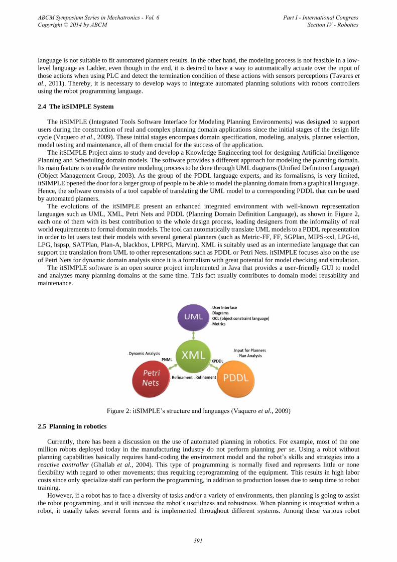
The evolutions of the itSIMPLE present an enhanced integrated environment with well-known representation
languages such as UML, XML, Petri Nets and PDDL (Planning Domain Definition Language), as shown in Figure 2,
each one of them with its best contribution to the whole design process, leading designers from the informality of real
world requirements to formal domain models. The tool can automatically translate UML models to a PDDL representation
in order to let users test their models with several general planners (such as Metric-FF, FF, SGPlan, MIPS-xxl, LPG-td,
LPG, hspsp, SATPlan, Plan-A, blackbox, LPRPG, Marvin). XML is suitably used as an intermediate language that can
support the translation from UML to other representations such as PDDL or Petri Nets. itSIMPLE focuses also on the use
of Petri Nets for dynamic domain analysis since it is a formalism with great potential for model checking and simulation.
The itSIMPLE software is an open source project implemented in Java that provides a user-friendly GUI to model
and analyzes many planning domains at the same time. This fact usually contributes to domain model reusability and
maintenance.
Figure 2: itSIMPLE’s structure and languages (Vaquero et al., 2009)
2.5 Planning in robotics
Currently, there has been a discussion on the use of automated planning in robotics. For example, most of the one
million robots deployed today in the manufacturing industry do not perform planning per se. Using a robot without
planning capabilities basically requires hand-coding the environment model and the robot’s skills and strategies into a
reactive controller (Ghallab et al., 2004). This type of programming is normally fixed and represents little or none
flexibility with regard to other movements; thus requiring reprogramming of the equipment. This results in high labor
costs since only specialize staff can perform the programming, in addition to production losses due to setup time to robot
training.
However, if a robot has to face a diversity of tasks and/or a variety of environments, then planning is going to assist
the robot programming, and it will increase the robot’s usefulness and robustness. When planning is integrated within a
robot, it usually takes several forms and is implemented throughout different systems. Among these various robot
ABCM Symposium Series in Mechatronics - Vol. 6 Copyright © 2014 by ABCM
Part I - International Congress Section IV - Robotics
591

planning forms, there is some in particular: path and motion planning, perception planning, navigation planning,
manipulation planning and domain-independent planning.
Nowadays, the maturity of robot planning is mainly at the level of its domain-specific planners. Path and motion
planning is a mature area that relies on computational geometry and efficiently it uses probabilistic algorithms, which
enable manual programming of closed-loop controllers for these tasks that handle the uncertainty and the integration
between acting and sensing (Ghallab et al., 2004). These high-level reactive controllers permit pre-programmed, goal-
directed and event-reactive modalities.
A perfect example of a robot that utilizes advanced automated planning is the Curiosity, shown in Figure 3. Curiosity
is a Mars Explorer Rover (MER) - it is a car-size robot designed by NASA and developed to explore the Mar’s surface.
Using 17 cameras, scientists are able to choose the most suitable path to be covered. The robot also possesses an arm
equipped with a drill, a brush to remove dust and a shovel to collect materials for analyses. In addition, in the Curiosity
body are located computers that use planners to define the robot actions.
Figure 3: Curiosity robot picture © NASA
3. CASE STUDY
The problem approached in this work is a simple production system. It consists of two conveyor belts (input and
output ones), a site where assembly is performed and a buffer to store parts if necessary. There are two types of parts
(base and cover) and the robot must perform both the transport and the assembly of these components. Figure 4 illustrates
this system.
Figure 4: Robotic System
In this problem, the robot must be programmed and trained in order to perform different tasks (grab, move and drop),
always analyzing the presence and the type of the part.
Follow, two different robot programming methods for this system will be presented. The first method is about the
classical programming that is developed in the robot controller and the robot is trained to realize the set of tasks. The
ABCM Symposium Series in Mechatronics - Vol. 6 Copyright © 2014 by ABCM
Part I - International Congress Section IV - Robotics
592

second method uses automated planning, in which the system is modeled and the evaluation of the conditions generates
the plans (task set) that the robot must realize.
3.1 Classical robot programming method
In the classical robot programming method, firstly the trajectories and actions to be performed are defined. After, this
implementation in the robot controller begins with the definition of the kind of movement, speed and precision level.
Later, the robot is trained to carry through these movements in definitive fixed sequence.
For the case study, the robot will need to develop the following actions:
• FMove(Initial_position,Conveyor Belt)
• OMove(Conveyor Belt,Buffer)
• FMove(Buffer, Conveyor Belt)
• OMove(Conveyor Belt, Assembling)
• FMove(Assembling, Conveyor Belt)
• OMove(Buffer, Assembling)
• FMove(Assembling,Buffer)
• OMove(Assembling, Output)
• FMove(Output, Initial_position)
• FMove(Output, Conveyor Belt)
• GrabPart(Close Gripper)
• DropPart(Open Gripper)
• PartAssembly (Open Gripper)
• GrabProd(Close Gripper)
• DropProd(Open Gripper)
The command FMove is a free movement (robot without any part) and OMove is a robot movement with the part. The
other actions are of Grab or Drop the part (or product) and PartAssembly carry through the assembling.
The main characteristics of the movements are:
• OMove - low speed, because the robot is handling the part
• FMove - high speed, because the robot is moving freely.
• In approach points the speed must be low
• Position Level (movement precision level) will be higher when the actions will be executed to catch and to drop
The conditions (part presence and type) are given through the read values in the sensors and will be parameters to
determine a certain command execution.
The previously modeled system was mounted using a robot MOTOMAN-HP6 for accomplishment of the
programming, training and tests. Figure 5 presents a picture of the assembly system.
Figure 5: Picture of the assembly system.
The tasks are divided into Jobs, which are programs with the movements and actions necessary to accomplish the
transport of part / product and the assembly of the product.
ABCM Symposium Series in Mechatronics - Vol. 6 Copyright © 2014 by ABCM
Part I - International Congress Section IV - Robotics
593
The Jobs required for this case study are:
Job1: MOVL, Initial_position,Conveyor Belt
Close Gripper
Job2: MOVL , Conveyor Belt,Buffer
Open Gripper
Job3: MOVL, Conveyor Belt, Assembling
Open Gripper
Job4: MOVL, Buffer, Conveyor Belt
Close Gripper
Job5: MOVL, Assembling, Conveyor Belt
Close Gripper
Job6: MOVL, Assembling,Buffer
Close Gripper
Job7: MOVL, Buffer, Assembling
Open Gripper
Job8: Close Gripper (GrabProd)
MOVL, Assembling, Output
Open Gripper (DropProd)
Job9: MOVL, Output, Initial_position
Job10: MOVL, Output, Conveyor Belt
Close Gripper
Job11: MOVL, Conveyor Belt, Assembling
Open Gripper (PartAssembly)
Job12: MOVL, Buffer, Assembling
Open Gripper (PartAssembly)
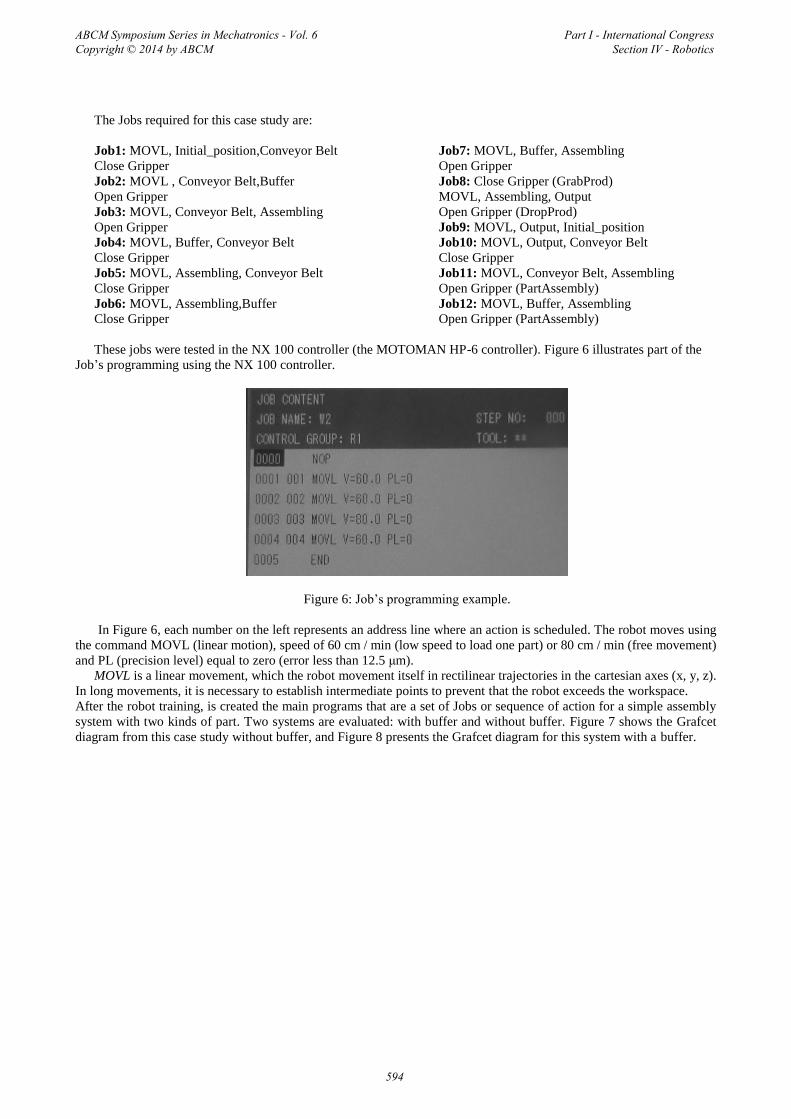
These jobs were tested in the NX 100 controller (the MOTOMAN HP-6 controller). Figure 6 illustrates part of the
Job’s programming using the NX 100 controller.
Figure 6: Job’s programming example.
In Figure 6, each number on the left represents an address line where an action is scheduled. The robot moves using
the command MOVL (linear motion), speed of 60 cm / min (low speed to load one part) or 80 cm / min (free movement)
and PL (precision level) equal to zero (error less than 12.5 μm).
MOVL is a linear movement, which the robot movement itself in rectilinear trajectories in the cartesian axes (x, y, z).
In long movements, it is necessary to establish intermediate points to prevent that the robot exceeds the workspace.
After the robot training, is created the main programs that are a set of Jobs or sequence of action for a simple assembly
system with two kinds of part. Two systems are evaluated: with buffer and without buffer. Figure 7 shows the Grafcet
diagram from this case study without buffer, and Figure 8 presents the Grafcet diagram for this system with a buffer.
ABCM Symposium Series in Mechatronics - Vol. 6 Copyright © 2014 by ABCM
Part I - International Congress Section IV - Robotics
594

Figure 7: Grafcet of system without buffer Figure 8: Grafcet of system with buffer
In the simplest system (without buffer) only four actions are carried through. The robot moves itself of the initial
position for the conveyor belt, catches the part, takes the part for the assembly and later returns for the conveyor belt and
it repeats the process with other part. When it arrives again in the assembly, the robot accomplishes the product
assembling. For the product assembly the type of part condition must be respected. After the assembly, the product is
carried to the output. In this case, the part sequence must be pre-determined, restricting the input parts flexibility – in
other words, it is necessary that the base is provided before the cover, ensuring the product assembly.
With buffer, it is necessary more analyses and actions. Depending on the kind of part, the robot must store it in the
buffer and take for the assembly only when its corresponding type arrives. For this reason, parts can arrive in any sequence
and the buffer is going to be used to reach a suitable assembly sequence.
3.2 Robot Programming method with Automated Planning
Another approach is using of automated planning to define the sequence of jobs that the robot must to execute. The
system must be modeled and well specified (with the objective and conditions definitions) for the development of the
plans, aiming at to reach the objective that, in this in case is the mounted product in the output.
The modeling process begins with the Use Cases Diagram, as shown in Figure 9. An analysis of the proposed problem
characteristics allows the identification of three actors, the Robot, the Part and the Product. The actor Robot will be
responsible for carrying out the Use Case Grab and Drop, the actor Part will be transported for Robot while the actor
Product will be compose for two parts on the assembling place.
The Use Case FreeMove, OccupiedMove, Grab and Drop requires the activities of both Robot and Part actors
simultaneously while the Use Case PartAssembly, ProdGrab and ProdDrop requires the activities of both Robot and
Product actors.
ABCM Symposium Series in Mechatronics - Vol. 6 Copyright © 2014 by ABCM
Part I - International Congress Section IV - Robotics
595
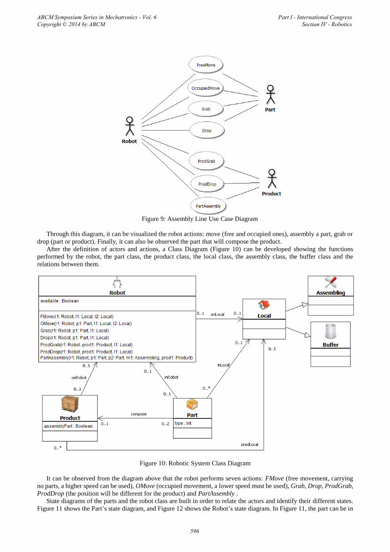
Figure 9: Assembly Line Use Case Diagram
Through this diagram, it can be visualized the robot actions: move (free and occupied ones), assembly a part, grab or
drop (part or product). Finally, it can also be observed the part that will compose the product.
After the definition of actors and actions, a Class Diagram (Figure 10) can be developed showing the functions
performed by the robot, the part class, the product class, the local class, the assembly class, the buffer class and the
relations between them.
Figure 10: Robotic System Class Diagram
It can be observed from the diagram above that the robot performs seven actions: FMove (free movement, carrying
no parts, a higher speed can be used), OMove (occupied movement, a lower speed must be used), Grab, Drop, ProdGrab,
ProdDrop (the position will be different for the product) and PartAssembly .
State diagrams of the parts and the robot class are built in order to relate the actors and identify their different states.
Figure 11 shows the Part’s state diagram, and Figure 12 shows the Robot’s state diagram. In Figure 11, the part can be in
ABCM Symposium Series in Mechatronics - Vol. 6 Copyright © 2014 by ABCM
Part I - International Congress Section IV - Robotics
596

two different states, Still or Moving. The robot actions Grab or Drop the part and the conditions evaluation (p1.inLocal
or p1.inRobot) can determinate the change of states. In Figure 12 are shown the actions (Drop, prodDrop, Grab,
prodGrab, Fmove, Omove and PartAssembly) and conditions (r1.available = true or false) for the change of robot states
(Free or Occupied).
The product’s state diagram is similar to the part’s state diagram.
Figure 11: Part´s State Diagram
Figure 12: Robot´s State Diagram
The pre and post-conditions of actions that the objects of Robot Class performs are extracted from descriptions of Use
Cases and these are represented in OCL - Object Constraint Language (OMG – Object Management Group, 2003). The
example below shows a condition in the robot’s state diagram.
p1.inLocal = l1 and p1.inRobo = null
Its means that Part is in one Local and not in the Robot.
3.3 Problem Definition
Once the planning domain was modeled, the planning problem can be modeled by two distinct Snapshots (Objects
Diagram) representing the initial state and goal state of the problem. For didactic reasons, this paper is presenting only
two Parts (p1 and p2) to be assembled as product and does not requires the buffer. Initially, the Robot is set in Initial
Position; two parts is on conveyor belt (input). The final state, defined as a goal snapshot is: two parts compose a Product
and this in the output; Figure 13 and Figure 14 shows the initial snapshot and the goal snapshot corresponding to this
problem.
ABCM Symposium Series in Mechatronics - Vol. 6 Copyright © 2014 by ABCM
Part I - International Congress Section IV - Robotics
597

Figure 13: Initial Snapshot
Figure 14: Goal Snapshot
The itSIMPLE has a significant number of automated planners, such as SGPlan6 (Hsu and Wah, 2008), Metric-FF
(Hoffmann, 2003). This work presents the result obtained with the Metric-FF planner, which generated the plan-solutions
described below.
1- (FMove, Robot, IniPos, Conveyor Belt)
2- (Grab, Robot P1, Conveyor Belt)
3- (OMove, Robot P1, Conveyor Belt, Assembling)
4- (Drop, Robot P1, Assembling)
5- (FMove, Robot, Assembling, Conveyor Belt)
6- (Grab, Robot P2, Conveyor Belt)
7- (OMove, Robot P2, Conveyor Belt, Assembling)
8- (Drop, Robot P2, Assembling)
9- (PartAssembly P2 P1, Assembling, Product)
10- (ProdGrab, Robot, Prod, Assembling)
11- (OMove, Robot P2, Assembling, Output)
12- (ProdDrop, Robot, Product, Output)
It can be seen that twelve steps are necessary to solve the problem. The robot moves from its initial position, grabs
one part from the conveyor and transports it to the assembling area. After that, it collects another part on the conveyor
and moves it to assembly. Finally, the robot assembles the two parts, grabs the product and carries it to the output conveyor
belt.
ABCM Symposium Series in Mechatronics - Vol. 6 Copyright © 2014 by ABCM
Part I - International Congress Section IV - Robotics
598

The generated plan steps present one direct relationship with the previously defined Jobs on classical robot
programming method. This relationship is shown hereafter:
• Job1: steps 1 and 2
• Job3: steps 3 and 4
• Job5: steps 5 and 6
• Job11: steps 7,8 and 9
• Job8: steps 10 e 11 and 12
Therefore, to execute this plan on classical method would be necessary only a sequence of five jobs.
4. CONCLUSION
This paper describes how to realize classical programming and apply automated planning tools in assembly and
disassembly Robot system. With itSIMPLE it is possible to generate several initial and goal Snapshots related to real
cases; that is, solving several different problems without re-programming. Each generated solution-plan action must be
mapped as Robot Language. On the other hand, it is not possible to generate a cyclic and recursive solution; each problem
requires another initial snapshot and a new solution-plan must be created, which requires time processing.
The best scenario for the automated planning application in manufacturing automation would be the integration of
disparate languages, in this case, PDDL and Robot Language.
The integration of these two boarding, would promote the insertion of an intelligent behavior on the diverse types of
industrial systems with robot use, such as the automotive industry, oil industry, mining and others, beyond advantages as
adaptability, reduction of uncertainties and forecast of behavior.
This integration would be possible by developing an application capable of performing an interface between Robot
and itSIMPLE. The development of an application for the automatic integration between the planner allocated in
itSIMPLE and the process controller from PDDL to Jobs (actions of robot) is a main further work. This interface will
communicate them through DLL, OPC server or a built driver. The idea of this interface is better described in Fonseca et
al (2013).
Figure 15: Runtime processes
In Figure 15, it can be observed an interface between the plan domain (using the itSIMPLE) and the robot. Having
defined the list of actions, the system begins to operate until the goal snapshot or an unexpected state is reached. The
interface will convert a PDDL plan into a set of actions using the robot language (Jobs). In the case of an unexpected
state, the system will request a re-planning for an automated planner.
The automated planning presents more flexibility and simple efficiency for solutions in a specific domain, and
modifications can be made offline not causing robot stop. In classical modeling system a small modification of parameters
such as addition of part types becomes the program more complex and dependent on the programmer.
ABCM Symposium Series in Mechatronics - Vol. 6 Copyright © 2014 by ABCM
Part I - International Congress Section IV - Robotics
599
This is an only initial study which intends to stimulate automated planning deployment. There is a need to compare
planner solutions in more complex examples and to compare it with the results obtained by using traditional programming.
5. ACKNOWLEDGEMENTS
Authors are grateful to Prof. Dr. Marcus Antonio Viana Duarte, Prof. Dr. Ricardo Fortes de Miranda, UFU, FEMEC
FAU, CAPES, FAPEMIG and CNPQ.
6. REFERENCES
Blum, A. and Furst, M. (1997). Fast planning through planning graph analysis. Artificial intelligence. 90:281-300.
Ernst, G.W. and Newell, A. (1969). GPS: a case study in generality and problem solving. Academic Press. (revised
version of Ernst's 1966 dissertation, Carnegie Institute of Technology.)
Fikes, R. E. and Nilsson N. J. (1971). Strips: A new approach to the application of theorem proving to problem
solving. Journal of Artificial Intelligence, volume (2), 189-208.
Fonseca, J.P.S., Cardozo, R.N., Guimarães, W.H.P., Ribeiro, K.S., Sousa, A.R., Tavares, J.J.P.Z.S., Carvalho, J.C.M.
(2012). Automated Planning and Real Systems Based on PLC: A Practical Application in a Didactic Bench of
Manufacturing Automation. In Proceedings of the Tampra Workshop at 22nd International Conference on Automated
Planning and Scheduling (ICAPS), Atibaia, Brazil, 37-44.
Fonseca, J.P.S., Sousa,A., Ferreira, M.V., Tavares, J.J.P.Z.S., Carvalho, J.C.M. (2013) Planpas – Plans Parser for
Automated Systems. In proceedings of 11th IFAC Workshop on Intelligent Manufacturing Systems – IMS 2013, May 22-
23, 2013, São Paulo, Brazil. To be presented.
Fox, M., and Long, D. 2003. PDDL2.1: An Extension of Pddl for Expressing Temporal Planning Domains. Journal
of Artificial Intelligence Research, 20:61–124.
Gerevini, A., Saetti, A., Serina, I. and Toninelli, P. 2004. LPG-TD: a Fully Automated Planner for PDDL2.2
Domains. In American Association for Artificial Intelligence (AAAI).
Ghallab, M., Nau, D., Traverso, P. 2004. Automated Planning: theory and practice. Morgan Kaufmann Publishers,
May 2004
Groover, M. P. Automação industrial e sistemas de manufatura / Mikell P. Groover [et al.]; tradução Jorge Ritter,
Luciana do Amaral Teixeira, Marcos Vieira; revisão técnica José Hamilton Chaves Gorgulho Júnior – 3.ed – São Paulo:
Pearson Prentice Hall, 2011
Hoffmann, J. The Metric-FF planning system: Translating “ignoring delete lists” to numeric state variables. 2003.
Journal of Artificial Intelligence Research, 20:291–341.
Hsu, C.W. and Wah, B.W. 2008. The SGPlan Planning System in IPC-6. Illinois, Usa: University Of Illinois, 2008.
3 p.
McDermott, D., Ghallab, M., Howe, A., Knoblock, C., Ram, A., Veloso, M., Weld, D., Wilkins, D. (1998). PDDL-
The Planning Domain Definition Language, New Haven, CT: Yale Center for Computational Vision and Control.
Motoman, “NX100 Controller Manual” – Motoman, West Carrollton, 2006
Motoman, Robótica do Brasil. “Treinamento em programação de Nível Básico e Intermediário para o Controlador
NX100”, Manual técnico, Motoman, São Bernado do Campo, 2009
Murata, T. (1989). Petri Nets: Properties, Analysis and Applications. In IEEE Proceedings, volume (12) no.04.
OMG – Object Management Group. Unified Modeling Language specification. Available at:
<http://www.omg.org/uml>. Accessed on: 18/12/2012.
OPC Foundation. (2012). OPC XML-DA Specification. Available at:
http://www.opcfoundation.org/Default.aspx/04_tech/04_spec_xml.asp. Accessed in 19/12/2012.
Reuters (2013), Luciana Otoni, Brasília < http://noticias.bol.uol.com.br/economia/2013/01/15/setor-industrial-
estadisposto-a-ampliar-investimentos-em-2013--cni.jhtm >
Tavares, J.J.P.Z.S., Fonseca, J.P.S., Vaquero, T.S., and Silva, J.R. (2011). Integração de Planejamento Automático e
Sistemas Reais Baseados em CLP. In Proceedings of X Simpósio Brasileiro de Automação Inteligente, São João Del Rey,
Brazil, 1226-1231.
Vaquero, T.S. (2007). ITSIMPLE: Ambiente integrado de análise de domínios de planejamento automático. 316 f.
MsC. diss. University of São Paulo, São Paulo, Brazil.
ABCM Symposium Series in Mechatronics - Vol. 6 Copyright © 2014 by ABCM
Part I - International Congress Section IV - Robotics
600

Vaquero, T.S.; Silva, J.R.; Ferreira, M.; Tonidandel, F.; Beck, J.C. From Requirements and Analysis to PDDL in
itSIMPLE3.0. In: Proceedings of the 3rd International Competition on Knowledge Engineering for Planning and
Scheduling. ICAPS-09. Thessaloniki, Greece. 2009.
7. RESPONSIBILITY NOTICE
The authors are the only responsible for the printed material included in this paper.
ABCM Symposium Series in Mechatronics - Vol. 6 Copyright © 2014 by ABCM
Part I - International Congress Section IV - Robotics
601