Analysis of a Wearable Robotic System for Ankle Rehabilitation
16
machines Article Analysis of a Wearable Robotic System for Ankle Rehabilitation † Matteo Russo 1 and Marco Ceccarelli 2, * 1 The Rolls-Royce UTC in Manufacturing and On-Wing Technology, Faculty of Engineering, University of Nottingham, Nottingham NG8 1BB, UK; [email protected] 2 LARM 2 : Laboratory of Robot Mechatronics, University of Rome “Tor Vergata”, 00133 Rome, Italy * Correspondence: [email protected] † This work is an expansion of a paper presented at The 3rd International Conference of IFToMM Italy (IFIT 2020): Russo, M., Ceccarelli, M. A wearable device for ankle motion assistance. In Advances in Italian Mechanism Science: Mechanisms and Machine Science 91, Springer, Cham, Switzerland, 2020 (in print). Received: 10 August 2020; Accepted: 26 August 2020; Published: 27 August 2020 Abstract: As one of the most commonly injured joints of the human body, the ankle is often subject to sprains or fractures that require motion assistance to recover mobility. Whereas physiotherapists usually perform rehabilitation in one-on-one sessions with patients, several successful robotic rehabilitation solutions have been proposed in the last years. However, their design is usually bulky and requires the patient to sit or stand in a static position. A lightweight wearable device for ankle motion assistance, the CABLEankle, is here proposed for motion ankle exercising in rehabilitation and training. The CABLEankle is based on a cable-driven S-4SP S parallel architecture, which enables motion assistance over the large motion range of the human ankle in a walking gait. The proposed mechanism design is analyzed with kinematic and static models, and the force closure workspace of the mechanism is discussed with analytical results. Finally, the feasibility of the proposed design is investigated through numerical simulations over the ankle motion range as a characterization of the peculiar motion. Keywords: service robotics; medical devices; rehabilitation; parallel manipulators; cable-driven robots 1. Introduction The ankle joint is critical to locomotion by sustaining the load of the whole body while exerting key forces during push-off, leg swing, and center of mass advancement during the human gait [1]. Unfortunately, it is also one of the most commonly injured joints of the human body, often subject to sprains or fractures that hinder or impede a full walking capability of a patient [2]. In order to recover full mobility, rehabilitation and motion assistance are required [3]. Rehabilitation training is usually performed by a physiotherapist in one-on-one sessions with a patient because it requires the physiotherapist’s full attention. Robot-assisted rehabilitation was proposed as an efficient alternative, since it would enable a single physiotherapist to assist multiple patients at the same time, potentially teleoperating the robots from a remote location. The feasibility of a robotic solution for the assistance of patients in the recovery of gait functions has been proved by several research groups [4–7]. However, most of the ankle rehabilitation robots are based on static platform designs, as illustrated in [8–16]. In the work in [8], rehabilitation is performed with the patient standing on two platforms with variable orientation. This solution requires the patient to be able to stand up, and it is characterized by a bulky (non-portable) device. Another grounded design is proposed in [9] for the rehabilitative exercise of a single leg, which is similar to the prototype in [10] with a mechanism driven by pneumatic muscles. An evolution Machines 2020, 8, 48; doi:10.3390/machines8030048 www.mdpi.com/journal/machines
Transcript of Analysis of a Wearable Robotic System for Ankle Rehabilitation

machines
Article
Analysis of a Wearable Robotic System for AnkleRehabilitation †
Matteo Russo 1 and Marco Ceccarelli 2,*1 The Rolls-Royce UTC in Manufacturing and On-Wing Technology, Faculty of Engineering,
University of Nottingham, Nottingham NG8 1BB, UK; [email protected] LARM2: Laboratory of Robot Mechatronics, University of Rome “Tor Vergata”, 00133 Rome, Italy* Correspondence: [email protected]† This work is an expansion of a paper presented at The 3rd International Conference of IFToMM Italy
(IFIT 2020): Russo, M., Ceccarelli, M. A wearable device for ankle motion assistance. In Advances in ItalianMechanism Science: Mechanisms and Machine Science 91, Springer, Cham, Switzerland, 2020 (in print).
Received: 10 August 2020; Accepted: 26 August 2020; Published: 27 August 2020�����������������
Abstract: As one of the most commonly injured joints of the human body, the ankle is often subject tosprains or fractures that require motion assistance to recover mobility. Whereas physiotherapistsusually perform rehabilitation in one-on-one sessions with patients, several successful roboticrehabilitation solutions have been proposed in the last years. However, their design is usually bulkyand requires the patient to sit or stand in a static position. A lightweight wearable device for anklemotion assistance, the CABLEankle, is here proposed for motion ankle exercising in rehabilitationand training. The CABLEankle is based on a cable-driven S-4SPS parallel architecture, which enablesmotion assistance over the large motion range of the human ankle in a walking gait. The proposedmechanism design is analyzed with kinematic and static models, and the force closure workspace ofthe mechanism is discussed with analytical results. Finally, the feasibility of the proposed design isinvestigated through numerical simulations over the ankle motion range as a characterization of thepeculiar motion.
Keywords: service robotics; medical devices; rehabilitation; parallel manipulators; cable-driven robots
1. Introduction
The ankle joint is critical to locomotion by sustaining the load of the whole body while exertingkey forces during push-off, leg swing, and center of mass advancement during the human gait [1].Unfortunately, it is also one of the most commonly injured joints of the human body, often subjectto sprains or fractures that hinder or impede a full walking capability of a patient [2]. In order torecover full mobility, rehabilitation and motion assistance are required [3]. Rehabilitation training isusually performed by a physiotherapist in one-on-one sessions with a patient because it requires thephysiotherapist’s full attention.
Robot-assisted rehabilitation was proposed as an efficient alternative, since it would enablea single physiotherapist to assist multiple patients at the same time, potentially teleoperating therobots from a remote location. The feasibility of a robotic solution for the assistance of patients in therecovery of gait functions has been proved by several research groups [4–7]. However, most of theankle rehabilitation robots are based on static platform designs, as illustrated in [8–16]. In the workin [8], rehabilitation is performed with the patient standing on two platforms with variable orientation.This solution requires the patient to be able to stand up, and it is characterized by a bulky (non-portable)device. Another grounded design is proposed in [9] for the rehabilitative exercise of a single leg,which is similar to the prototype in [10] with a mechanism driven by pneumatic muscles. An evolution
Machines 2020, 8, 48; doi:10.3390/machines8030048 www.mdpi.com/journal/machines

Machines 2020, 8, 48 2 of 16
of the same design is reported in [11]. Smaller but still grounded devices are introduced in [12] and [13]as based on a high-performance parallel architecture and a compliant mechanism, respectively.
All these robots are characterized by static designs, and most of them, such as the prototypesin [14–16], are fixed to the ground or are difficult to move due to a large footprint and weight. In orderto overcome this limit, few research groups have proposed wearable designs such as ankle exoskeletonsand orthoses [3,17]. These wearable rehabilitation systems are usually characterized by rigid orcompliant links and bulky bodies, thus still requiring additional support for their significant weight.
Cable-driven robots may solve all these issues thanks to their lightweight structures. Additionally,they can be safer than conventional mechanisms thanks to their negligible moving mass [18]. Portablecable-driven rehabilitation robots have already been introduced in [18–20] for legs and elbows. In fact,cable-driven parallel mechanisms have recently attracted attention even in specific applications,as reported in the dedicated conference series in [21], where nevertheless the topic of ankle assistancedevices is not analyzed. Only a few research groups have proposed static (non-portable) designs forankle rehabilitation [22,23]. In particular, the work in [22] studies the feasibility of cable-driven anklerehabilitation without proposing a specific design. A grounded platform is described in [23], but itsfour cables are not enough to enable full control of the ankle joint, since the proposed device is fixed tothe foot but not to the shank of the patient. While three degrees of freedom is enough to control the footmotion with respect to the leg, grounded designs require either more degrees of freedom or additionalconstraints to the leg. According to the authors’ knowledge, there is no portable cable-driven solutionavailable for ankle motion assistance.
The CABLEankle is presented in this paper as a lightweight wearable robot for ankle motionassistance with a cable-driven architecture. The CABLEankle is inspired by the CADEL architecturefirst presented in [20], which can be modeled as a cable-driven S-4SPS parallel mechanism. The originalelbow rehabilitation mechanism is adapted to the new geometric and motion requirements for ankles.In [24], the conceptual design of the CABLEankle is briefly introduced with its kinematic model anda numeric simulation for a limited two-degree-of-freedom motion range. This manuscript expands theresearch work of [24] with a detailed kinematic and static analysis that includes a novel formulation forthe force-closure model of the proposed cable-driven mechanism. Furthermore, a numerical simulationis included to validate the feasibility of the CABLEankle for the full ankle mobility range, in order tocharacterize the performance of this novel design in terms of motion range, cable tension, load on theankle joint, and motor power.
2. Materials and Methods
In this section, the design process of the proposed ankle rehabilitation device is reported withthe main methods used to synthesize and analyze the mechanism. First, motion requirements aredefined by studying the biomechanics of the human ankle joint, with a focus on its mobility. Then,the conceptual design of the mechanism is introduced with its main characteristics. A closed-formanalytical solution is provided for the kinematics of the proposed device, which is needed to actuateand control the ankle motion. A static model is then reported to evaluate cable tension and anklejoint reaction forces during motion. Finally, a novel formulation for force-closure of cable-drivenmechanisms is also presented in this paper to validate the feasibility and the performance of the devicein its workspace.
2.1. Motion Requirements from Ankle Biomechanics
The ankle joint complex connects the lower leg and the foot, and it is made up of three main joints,namely the talocalcaneal, tibiotalar, and transverse-tarsal joint. It can sustain large compressive andshear forces while keeping a high degree of stability during gait [25]. The complex mobility of the anklecan be approximated by its three main motion modes, which are illustrated in Figure 1: plantarflexionand dorsiflexion, in the sagittal plane; abduction and adduction, in the transverse plane; inversion andeversion, in the frontal plane.
Machines 2020, 8, 48 3 of 16
Machines 2020, 8, x FOR PEER REVIEW 3 of 16
plantarflexion and dorsiflexion, in the sagittal plane; abduction and adduction, in the transverse plane; inversion and eversion, in the frontal plane.
The ranges of motion of these modes are characterized by a significant variability between individuals, due to geographical/cultural differences, anatomical structures, and distinct data-acquisition methodologies. In order to define a target range of motion for an ankle-assisting device, conservative values for the ankle range of motion as per Figure 1 have been extracted from [25–27], as summarized in Table 1 referring to daily activities.
Design requirements may refer to healthy ranges of motion as in Table 1, but for motion assistance smaller ranges can be considered mainly in application for rehabilitant therapies and elderly people assistance. In addition to the kinematic aspects of the range of motion, requirements for design and operation purposes can be considered in terms of actions on the ankle to achieve a desired ankle movement either in full passive mode or with a user participation that can be controlled and guided. This action can be sized within a range of 1 to 20 N when considering unloaded ankle motion in the air and can be scaled up to more than 100 N if users stand up on the foot. In general, however, a rehabilitation therapy can be planned with a leg in the air. Therefore, the force requirements for the device developments can be assumed as less than 30 N, considering also possible exercise training to reinforce the ankle muscular system.
Table 1. Ranges of motion of the human ankle joint [25–27].
Motion Dorsiflexion Plantarflexion Abduction/Adduction
Inversion/Eversion
Range limits 20 deg 50 deg ±10 deg ±12 deg
Figure 1. Morphological motions of the human ankle joint.
2.2. Conceptual Design of a Wearable Device for Ankle Motion Assistance
Figure 2a shows a conceptual design of CABLEankle, a wearable device for ankle motion assistance. The above-mentioned issues are addressed with the indication of motion directions and with a scheme of a cable-driven system that is equipped also with suitable sensors (S) for monitoring and controlling purposes. The application of the device can range from motion guidance, as per exercise and augmentation of ankle capacity, to motion assistance, as per rehabilitation and physiatry ankle medical therapy.
The motion of the ankle with respect to the shank (part of a person’s leg between the knee and the ankle) is planned by the relative motion of a foot platform, which can even include a shoe for wearing the system, with respect to a shank platform, which can be ring-shaped to be worn on the shank. The motors (M) increase or decrease cable lengths to guide this relative motion with a
Figure 1. Morphological motions of the human ankle joint.
The ranges of motion of these modes are characterized by a significant variabilitybetween individuals, due to geographical/cultural differences, anatomical structures, and distinctdata-acquisition methodologies. In order to define a target range of motion for an ankle-assisting device,conservative values for the ankle range of motion as per Figure 1 have been extracted from [25–27],as summarized in Table 1 referring to daily activities.
Table 1. Ranges of motion of the human ankle joint [25–27].
Motion Dorsiflexion Plantarflexion Abduction/Adduction Inversion/Eversion
Range limits 20 deg 50 deg ±10 deg ±12 deg
Design requirements may refer to healthy ranges of motion as in Table 1, but for motion assistancesmaller ranges can be considered mainly in application for rehabilitant therapies and elderly peopleassistance. In addition to the kinematic aspects of the range of motion, requirements for design andoperation purposes can be considered in terms of actions on the ankle to achieve a desired anklemovement either in full passive mode or with a user participation that can be controlled and guided.This action can be sized within a range of 1 to 20 N when considering unloaded ankle motion inthe air and can be scaled up to more than 100 N if users stand up on the foot. In general, however,a rehabilitation therapy can be planned with a leg in the air. Therefore, the force requirements for thedevice developments can be assumed as less than 30 N, considering also possible exercise training toreinforce the ankle muscular system.
2.2. Conceptual Design of a Wearable Device for Ankle Motion Assistance
Figure 2a shows a conceptual design of CABLEankle, a wearable device for ankle motionassistance. The above-mentioned issues are addressed with the indication of motion directions andwith a scheme of a cable-driven system that is equipped also with suitable sensors (S) for monitoringand controlling purposes. The application of the device can range from motion guidance, as perexercise and augmentation of ankle capacity, to motion assistance, as per rehabilitation and physiatryankle medical therapy.

Machines 2020, 8, 48 4 of 16
Machines 2020, 8, x FOR PEER REVIEW 4 of 16
mechanical structure that is equipped of a pulley and servomotor. The control system can use information from sensors (S), which can be both on board of the device and worn by the patient. These sensors can include accelerometers and IMUs, which enable gait analysis as reported, for example, in [28]. Sensors (S) can be used not only for operation control of the device, but also for monitoring of ankle medical issues, such as for measures of temperature, muscle reaction and blood pressure, as required in the device application. Figure 2b shows a CAD design of a mechanical solution, highlighting the lightweight compact features of the conceptual design for portability and user-oriented operation. A power supply can also be integrated inside the foot platform, on the shank platform or in a box nearby the device.
(a)
(b)
Figure 2. Proposed solution for ankle motion assistance: (a) conceptual design of the CABLEankle with main components (M: motors, S: sensors); (b) A CAD design for the proposed conceptual scheme.
2.3. Kinematic Analysis
The proposed solution in Figure 2 is a cable-driven parallel mechanism that is inspired by the CADEL design for elbow rehabilitation in [20]. The device is characterized by a foot platform and a shank platform that are connected by four cables of varying length, as shown in the models of Figure
Figure 2. Proposed solution for ankle motion assistance: (a) conceptual design of the CABLEanklewith main components (M: motors, S: sensors); (b) A CAD design for the proposed conceptual scheme.
The motion of the ankle with respect to the shank (part of a person’s leg between the knee and theankle) is planned by the relative motion of a foot platform, which can even include a shoe for wearingthe system, with respect to a shank platform, which can be ring-shaped to be worn on the shank.The motors (M) increase or decrease cable lengths to guide this relative motion with a mechanicalstructure that is equipped of a pulley and servomotor. The control system can use information fromsensors (S), which can be both on board of the device and worn by the patient. These sensors can includeaccelerometers and IMUs, which enable gait analysis as reported, for example, in [28]. Sensors (S) canbe used not only for operation control of the device, but also for monitoring of ankle medical issues,such as for measures of temperature, muscle reaction and blood pressure, as required in the deviceapplication. Figure 2b shows a CAD design of a mechanical solution, highlighting the lightweightcompact features of the conceptual design for portability and user-oriented operation. A power supplycan also be integrated inside the foot platform, on the shank platform or in a box nearby the device.

Machines 2020, 8, 48 5 of 16
2.3. Kinematic Analysis
The proposed solution in Figure 2 is a cable-driven parallel mechanism that is inspired by theCADEL design for elbow rehabilitation in [20]. The device is characterized by a foot platform anda shank platform that are connected by four cables of varying length, as shown in the models of Figure 2.The two platforms are connected to the foot and the shank of the patient, respectively, by means ofstraps or equivalent comfortable means, and both of them can be assumed to be fixed to a patient’s legand foot. Thus, by varying the length of the cables, it is possible to activate a relative motion betweenfoot and shank, guiding the patient’s ankle motion. The kinematic behavior of the ankle motion can beapproximated by a spherical joint with limited angular motion. Therefore, it is possible to model theproposed solution as a lower-mobility parallel mechanism with three degrees of freedom, by usinga S-4SPS architecture, as shown in the model of Figure 3.
Machines 2020, 8, x FOR PEER REVIEW 5 of 16
shank platform that are connected by four cables of varying length, as shown in the models of Figure 2. The two platforms are connected to the foot and the shank of the patient, respectively, by means of straps or equivalent comfortable means, and both of them can be assumed to be fixed to a patient’s leg and foot. Thus, by varying the length of the cables, it is possible to activate a relative motion between foot and shank, guiding the patient’s ankle motion. The kinematic behavior of the ankle motion can be approximated by a spherical joint with limited angular motion. Therefore, it is possible to model the proposed solution as a lower-mobility parallel mechanism with three degrees of freedom, by using a S–4SPS architecture, as shown in the model of Figure 3.
(a) (b)
Figure 3. A kinematic scheme of the proposed solution in Figure 2: (a) with reference frames; (b) with motion variables.
The reference frame S of the shank platform is Oxyz, whereas the reference frame F of the foot platform is Ouvw, as in Figure 3a. A general relative motion of the ankle joint can be described by three consecutive rotations around different axes. Thus, by considering an intrinsic roll–pitch–yaw rotation, the orientation of the foot platform with respect to the shank platform can be expressed as = . In Figure 3b the ith cable’s upper extremity is attached to point Si of the shank platform, and its lower extremity is attached to the corresponding point Fi of the foot platform. The following hypotheses are assumed:
• All the cables are always kept in tension during a controlled motion; • The attachment point of each cable behaves as a spherical joint; • The varying length of the cable can be modeled as an actuated prismatic joint cable-link with a
negligible axial deformation, that can be ensured by a proper cross-section size, material choice (e.g., Dyneema cables), and thanks to the short length of the cables in the proposed application.
The position of the ith cable attachment is = for the shank platform and = for the foot platform. The ankle pose can be described as = , where α, β and γ are the intrinsic rotations around the z-, y- and x-axis, as previously defined. The actuation is expressed by = , where li is the distance between points Si and Fi of each cable, computed as the magnitude of vectors li in Figure 3. Vectorial loop-closure equations can be written for each cable as + + = (1)
The cable length vector can be computed from (1) as
Figure 3. A kinematic scheme of the proposed solution in Figure 2: (a) with reference frames; (b) withmotion variables.
The reference frame S of the shank platform is Oxyz, whereas the reference frame F of the footplatform is Ouvw, as in Figure 3a. A general relative motion of the ankle joint can be described bythree consecutive rotations around different axes. Thus, by considering an intrinsic roll–pitch–yawrotation, the orientation of the foot platform with respect to the shank platform can be expressed asSFR = Rz(α)Ry(β)Rx(γ). In Figure 3b the ith cable’s upper extremity is attached to point Si of theshank platform, and its lower extremity is attached to the corresponding point Fi of the foot platform.The following hypotheses are assumed:
• All the cables are always kept in tension during a controlled motion;• The attachment point of each cable behaves as a spherical joint;• The varying length of the cable can be modeled as an actuated prismatic joint cable-link with
a negligible axial deformation, that can be ensured by a proper cross-section size, material choice(e.g., Dyneema cables), and thanks to the short length of the cables in the proposed application.
The position of the ith cable attachment is Ssi =(
six siy siz)T
for the shank platform andFfi =
(fix fiy fiz
)Tfor the foot platform. The ankle pose can be described as x =
(α β γ
)T,
where α, β and γ are the intrinsic rotations around the z-, y- and x-axis, as previously defined. The
actuation is expressed by q =(
l1 l2 l3 l4)T
, where li is the distance between points Si and Fi of

Machines 2020, 8, 48 6 of 16
each cable, computed as the magnitude of vectors li in Figure 3. Vectorial loop-closure equations canbe written for each cable as
OSi + SiFi + FiO = 0 (1)
The cable length vector can be computed from (1) as
Sli =SFRFfi −
Ssi (2)
Then, by computing the scalar product of each side of (2) by itself, the length of each cable can beexpressed as
li =√
SsTi
Ssi +FfT
iFfi − 2SsT
iSFRFfi (3)
As reported in Appendix A, the input–output relation can be obtained by deriving Equation (2), as
.q =
(SFRFf1 ×
Su1
)T
...(SFRFf4 ×
Su4
)T
.x (4)
where the ith cable unit vector is defined as ui.
2.4. Static Analysis
In both rehabilitation and assistance scenarios, the proposed device guides the assisted anklewith a controlled smooth motion, in order to avoid stress, pain or damage to a wearer. Because of thenegligible moving mass and the slow speed motion, dynamics and inertial effects can be neglected,and performance evaluation can be computed by using a static model as proposed in the following.When a generic wrench, which can be defined as force FW and moment MW, is applied to the footplatform, a static equilibrium can be achieved with a combination of the reaction at the ankle joint,in terms of reaction force FA and reaction moment MA, and of cable tension T, as in the scheme inFigure 4.
Machines 2020, 8, x FOR PEER REVIEW 6 of 16
= − (2)
Then, by computing the scalar product of each side of (2) by itself, the length of each cable can be expressed as = + − 2 (3)
As reported in Appendix A, the input–output relation can be obtained by deriving Equation (2), as
= ×⋮× (4)
where the ith cable unit vector is defined as ui.
2.4. Static Analysis
In both rehabilitation and assistance scenarios, the proposed device guides the assisted ankle with a controlled smooth motion, in order to avoid stress, pain or damage to a wearer. Because of the negligible moving mass and the slow speed motion, dynamics and inertial effects can be neglected, and performance evaluation can be computed by using a static model as proposed in the following. When a generic wrench, which can be defined as force FW and moment MW, is applied to the foot platform, a static equilibrium can be achieved with a combination of the reaction at the ankle joint, in terms of reaction force FA and reaction moment MA, and of cable tension T, as in the scheme in Figure 4.
Figure 4. A static model of the CABLEankle mechanism in Figure 2 with conditions for the equilibrium of the ankle assisted by the proposed device.
Thus, the equilibrium condition to translation in reference frame S is given by
+ + = (5)
where Ti is the tension in the ith cable, whereas the equilibrium condition to rotation is given by
× + + = (6)
Figure 4. A static model of the CABLEankle mechanism in Figure 2 with conditions for the equilibriumof the ankle assisted by the proposed device.

Machines 2020, 8, 48 7 of 16
Thus, the equilibrium condition to translation in reference frame S is given by
n∑i=1
Ti + FA + FW = 0 (5)
where Ti is the tension in the ith cable, whereas the equilibrium condition to rotation is given by
n∑i=1
fi × Ti + MA + MW = 0 (6)
By defining cable unit vector ui, the tension in the ith cable can be expressed as the productof its magnitude and limb unit vectors ui as Ti = −Tiui. The actuation vector T, with components(
T1 T2 T3 T4)T
, can be used to rewrite Equations (5) and (6) to get
UT·T− FA = FW (7)
and the equilibrium condition to rotation can be written as
AT·T−MA = MW (8)
with UT =[
u1 u2 u3 u4]
and AT =[
f1 × u1 · · · f4 × u4].
Since the ankle joint has been approximated as a spherical joint, it can constrain translationalmotion only, while reaction moment MA is a null vector within the ankle motion range. Therefore,the full equilibrium condition can be given by[
UT−I3
AT 03
](T
FA
)=
(FW
MW
)(9)
2.5. Force Closure
Unlike rigid links, cables can pull the two bodies together but cannot push. Thus, the resultsobtained from the kinematics in Equations (3) and (4) and from the static model in Equation (9) cannotbe directly applied to a real system. Therefore, the poses where the moving platform is fully constrainedby the cables must be determined maintaining positive cable tension as critical condition in constrainingthe moving platform. Hence, the force-closure workspace is a set of poses whereby resultant cabletensions can sustain an arbitrary external wrench acting on the moving platform, as pointed out in [29].
A general cable-driven parallel mechanism is said to have a force closure in a given pose ifand only if any arbitrary external wrench applied at the moving platform can be sustained throughappropriate positive tension forces in the cables [30,31]. The condition for force closure is usuallydescribed as
∀
(FW
MW
)∈ R6
∃ T1, . . . , T4 ∈ [0,∞) :[
UT−I3
AT 03
](T
FA
)=
(FW
MW
)(10)
A mathematical solution for a standard cable-driven parallel mechanism is well established inscientific literature for the case of n-DoF manipulator with n + 1 cables as reported, for example,in [29–32], but the mechanism under analysis has a hybrid structure with the ankle joint in parallelwith the cables. Therefore, a different approach is needed. Without any rigid joint, the force closurewould be verified for any of the following conditions:
1. The columns of[
UT
AT
]positively span R6;

Machines 2020, 8, 48 8 of 16
2. The convex hull of the column of[
UT
AT
]contains the neighborhood of the origin;
3. There does not exist a vector v ∈ R6, v , 0, such as that the scalar product of v and each column
of[
UT
AT
]is greater than or equal to 0.
However, the ankle joint is not modeled by those conditions, and it is therefore assumed that thecables must balance any wrench without the contribution of the joint reaction force (which can bothpull and push, differently from the cables). Thus, verifying force closure with those conditions wouldimpose unneeded design constraints by not considering the action of the ankle/leg.
Since the two platforms are connected by the ankle joint, the components of the wrench relative tothe degrees of freedom that are constrained by the joint can be fully balanced by the reaction of thejoint itself, while the cables are used to balance only the reaction moments relative to the idle rotationaldegrees of freedom. Therefore, the proposed motion assistance device can be said to have force closurein a given pose if and only if any arbitrary external wrench, which is applied at the moving platformand it cannot be balanced by the ankle joint, can be sustained through appropriate (positive) tensionforces in the cables. This definition of force closure can be mathematically expressed as
∀MW ∈ R3∃ T1, . . . , T4 ∈ [0,∞) : ATT = MW (11)
Therefore, force closure can be verified by any of the following conditions:
1. The columns of AT positively span Rm;2. The convex hull of the column of AT contains the neighborhood of the origin;3. There does not exist a vector v ∈ Rm, v , 0, such as that the scalar product of v and each column
of AT is greater than or equal to 0.
This novel definition of force closure drastically simplifies the solution for a cable-driven rotationaljoint. A simple example is here reported for a 2D dorsiflexion-plantarflexion motion that is characterizedby the simplified geometry in Figure 5. In this example, three possible positions are defined for thecables that will drive the rotation of the ankle around the Y-axis, defined by cable attachment pointsS1F1, S2F2 and S3F3, respectively. The main parameters of the example are defined in Table 2.
Machines 2020, 8, x FOR PEER REVIEW 8 of 16
(positive) tension forces in the cables. This definition of force closure can be mathematically expressed as ∀ ℝ ∃ , … , 0,∞ : = (11)
Therefore, force closure can be verified by any of the following conditions:
1. The columns of positively spanℝ ; 2. The convex hull of the column of contains the neighborhood of the origin; 3. There does not exist a vector ℝ , ≠ , such as that the scalar product of and each column
of is greater than or equal to 0.
This novel definition of force closure drastically simplifies the solution for a cable-driven rotational joint. A simple example is here reported for a 2D dorsiflexion-plantarflexion motion that is characterized by the simplified geometry in Figure 5. In this example, three possible positions are defined for the cables that will drive the rotation of the ankle around the Y-axis, defined by cable attachment points S1F1, S2F2 and S3F3, respectively. The main parameters of the example are defined in Table 2.
Table 2. Parameters of the force-closure example.
i × 1 −1 0 1 −1 0 −1 0 0 −1 0 −1 0 2 −2 0 1 −1 0 −1 0 0 −1 0 −2 0 3 1 0 1 −1 0 −1 0 0 −1 0 1 0
When considering a planar motion, the ankle joint has all translational degrees of freedom, thus allowing only the rotation around the y-axis. The other rotational degrees of freedom are out of the considered plane and therefore neglected in this example. Three possible combinations of cables are considered to drive the revolute joint, as shown in Table 3. When using Equation (11), the elements of matrix related to the rotation around the x-axis and the z-axis can be ignored, and by applying the second condition to verify force closure, it is possible to see that the 1D convex hull of the columns of the 1 + 2 case does not contain the neighborhood of the origin, while all the other options satisfy the condition. From a physical point of view, it can be noticed that to drive a rigid joint at least a cable on each side is needed to force rotation in both senses. While combinations 1 + 3 and 2 + 3 easily satisfy this condition, combination 1 + 2 cannot, as proved by the example. This calculation can be easily expanded and implemented for the 3D case (yielding a 3xN matrix , with N > 3, and a convex hull defined by N points in a 3D space).
Figure 5. A simplified 2D model of the proposed CABLEankle mechanism for an example of force closure with the proposed formulation.
Figure 5. A simplified 2D model of the proposed CABLEankle mechanism for an example of forceclosure with the proposed formulation.

Machines 2020, 8, 48 9 of 16
Table 2. Parameters of the force-closure example.
i si fi ui fi×ui
1(−1 0 1
)T (−1 0 −1
)T (0 0 −1
)T (0 −1 0
)T
2(−2 0 1
)T (−1 0 −1
)T (0 0 −1
)T (0 −2 0
)T
3(
1 0 1)T (
−1 0 −1)T (
0 0 −1)T (
0 1 0)T
When considering a planar motion, the ankle joint has all translational degrees of freedom,thus allowing only the rotation around the y-axis. The other rotational degrees of freedom are out ofthe considered plane and therefore neglected in this example. Three possible combinations of cablesare considered to drive the revolute joint, as shown in Table 3. When using Equation (11), the elementsof matrix AT related to the rotation around the x-axis and the z-axis can be ignored, and by applyingthe second condition to verify force closure, it is possible to see that the 1D convex hull of the columnsof the 1 + 2 case does not contain the neighborhood of the origin, while all the other options satisfy thecondition. From a physical point of view, it can be noticed that to drive a rigid joint at least a cable oneach side is needed to force rotation in both senses. While combinations 1 + 3 and 2 + 3 easily satisfythis condition, combination 1 + 2 cannot, as proved by the example. This calculation can be easilyexpanded and implemented for the 3D case (yielding a 3 ×N matrix AT, with N > 3, and a convex hulldefined by N points in a 3D space).
Table 3. Results of the force closure example.
Cables Bred Force Closure?
1 + 2[−1 −2
]NO
2 + 3[−2 1
]YES
1 + 3[−1 1
]YES
3. Results
By using the models developed in Section 2, a target ankle motion can be achieved thanks tothe Inverse Kinematic formulation in Equations (3) and (4), whereas the static model in (9) and theforce closure condition in (11) can be used as the base for a predictive force control to avoid the wearerfrom getting injured by excessive ankle load from the proposed CABLEankle operation. In addition,the above kinematics and force analysis can characterize the proposed design in terms of operationperformance for a practical implementation of a prototype in a near-future development.
Therefore, the proposed CABLEankle design can be validated on the average motion range ofthe human ankle, by evaluating its performance on the three motion modes of the ankle, namelydorsiflexion/plantarflexion, inversion/eversion, and adduction/abduction, as illustrated in Figure 1 andwith the numerical limits in Table 1. Each motion mode simulates a rotation from the lower to theupper limit of the ankle joint.
3.1. Kinematics
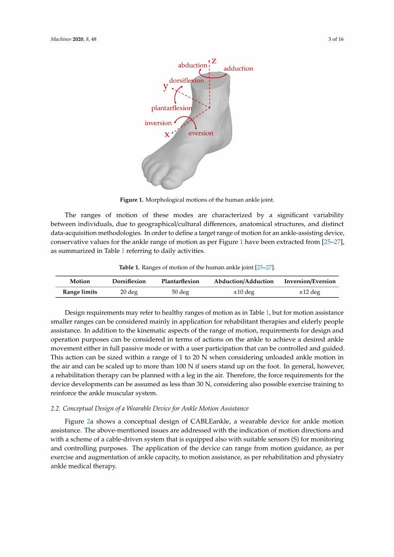
The design configuration of the device in Figure 2, for which patent data are given in in [33], ischaracterized by the geometry in Table 4 with the results of simulated operation in terms of elongationof the actuation cables, tension in the actuation cables, and load on the ankle joint, as in Figures 6–8,respectively. In the tested operations, each cable has a minimum length of 20 mm and a maximumlength of 200 mm. By using the Inverse Kinematic formulation in Equation (3), it is possible to computethe length of each cable for the simulated motion modes with the results that are illustrated in Figure 6.
Machines 2020, 8, 48 10 of 16
Table 4. Geometrical parameters of the example CABLEankle design in Figure 2 forperformance evaluation.
Shank Platform [mm] Foot Platform [mm] Joint Motion Limits
Ss1 =(
20 30 50)T Ff1 =
(80 75 −40
)Tα ∈ [−10◦; 10◦]
Ss2 =(−20 30 50
)T Ff2 =(
0 60 −40)T
β ∈ [−50◦; 20◦]
Ss3 =(
20 −30 50)T Ff3 =
(10 60 −40
)Tγ ∈ [−12◦; 12◦]
Ss4 =(−20 −30 50
)T Ff4 =(
90 60 −40)T li ∈ [20 mm; 200 mm]Machines 2020, 8, x FOR PEER REVIEW 10 of 16
(a)
(b)
(c)
Figure 6. Computed length of the actuation cables in a simulated full motion cycle: (a) dorsiflexion/plantarflexion; (b) inversion/eversion; (c) abduction/adduction.
Figure 6. Computed length of the actuation cables in a simulated full motion cycle: (a)dorsiflexion/plantarflexion; (b) inversion/eversion; (c) abduction/adduction.

Machines 2020, 8, 48 11 of 16Machines 2020, 8, x FOR PEER REVIEW 11 of 16
(a)
(b)
(c)
Figure 7. Computed tension in the actuation cables in a simulated full motion cycle: (a) dorsiflexion/plantarflexion; (b) inversion/Eversion; (c) abduction/adduction.
Figure 7. Computed tension in the actuation cables in a simulated full motion cycle: (a)dorsiflexion/plantarflexion; (b) inversion/Eversion; (c) abduction/adduction.

Machines 2020, 8, 48 12 of 16Machines 2020, 8, x FOR PEER REVIEW 12 of 16
(a)
(b)
(c)
Figure 8. Computed load on the ankle joint in a simulated full motion cycle: (a) Dorsiflexion/plantarflexion; (b) inversion/eversion; (c) abduction/adduction.
Figure 8. Computed load on the ankle joint in a simulated full motion cycle: (a)Dorsiflexion/plantarflexion; (b) inversion/eversion; (c) abduction/adduction.

Machines 2020, 8, 48 13 of 16
3.2. Statics and Force Closure
The static model of Equation (9) can be used to evaluate both the ankle joint reaction and thetension in the cables. The simulation results have been computed by assuming no external wrenchapplied onto the foot except for its own weight, with an estimated mass of 1.00 kg as per an exercise ofthe ankle on the air. The resulting values of cable tension for the simulated motion modes are reportedin Figure 7, whereas the load on the wearer’s ankle is shown in Figure 8.
The entire motion range of the ankle, as expressed in Table 1, is included in the force closureworkspace of the proposed cable-driven parallel robot, which is evaluated with the proposedformulation in Equation (11). This condition is essential to ensure that the motion of the anklecan be controlled by the cable-driven mechanism and that no unexpected/uncontrolled motionis allowed.
3.3. Power Consumption
By using the simulated motion data, it is also possible to compute the ideal power consumption ofthe system by assuming negligible losses due to friction and other external factors. For each simulatedmotion, the total time has been assumed equal to 5.0 s, representing a slow motion from the minimumto the maximum angle for rehabilitation purposes. The instantaneous power consumption Pm,i of theith motor can be estimated as
Pm,i = τm,iωm,i (12)
where τm,i is the motor torque, which can be computed by multiplying the tension in the ith cable andthe driving pulley diameter, and ωm,i is the angular velocity of the ith motor, which can be computedfrom the variation rate of the ith cable
.li, from vector
.q in Equation (4).
For the simulated motion modes, the overall power consumption of the four actuators in thesystem is characterized by a maximum value of 20 W when the mechanism moves in the upper limit ofits motion range in the inversion/eversion and adduction/abduction motion modes.
4. Discussion
The results in Figure 6 demonstrate that the proposed CABLEankle design can operate in the fullrange of motion of the ankle without reaching joint or device limits. with suitable smooth motion andlimited variation of the cable lengths. The largest variation of cable length is computed as 46 mm forcable 1 in Figure 6a and the smallest one is of 5 mm for cable 3 in Figure 6b.
The values of cable tension that are computed with the proposed static analysis for the simulatedmotion modes in Figure 7 have a maximum value of 90 N. Thus, they are safely within the maximumvalue that is allowed by a rotational motor driving the cable. Another key result from the staticanalysis is the load on the wearer’s ankle, as shown in Figure 8. The force acting on the ankle isreported in terms of its cartesian components to emphasize the influence of motion direction, with thecomponent along the x-axis of the foot as per Figure 1 being the most significant one, whereas thevertical component along the z-axis shows the largest variability. During the simulated motion, the loadreaches a maximum with 60 N, which is well sustainable with a healthy ankle but could be dangerous inthe case of rehabilitation of an injured one. In that case of rehabilitation exercise, the inversion/eversionand abduction/adduction motions should be limited to a range less than 10 deg with a suitable ankleload smaller than 30 N. With such a practical range of assisted motion, the tension in the cables arereduced conveniently up to much less than the computed maximum of 90 N.
The low power consumption of the prototype means that the proposed device can be powered byportable batteries. A 10,000 mAh battery, for example, can guarantee up to two hours of continuousfunctioning, thus removing the need for an external power supply. A power supply with commercialbatteries can be integrated in the foot platform, on the shank platform or in a box nearby the device.Thus, the device can include the battery, the motors, a small control board and a Bluetooth module,removing the need for complicated electrical wire routing between different bodies of the robot.
Machines 2020, 8, 48 14 of 16
A portable battery, combined with an estimated weight of 2.0 kg (of which 0.7 kg of prototype and1.3 kg of battery), makes the proposed design truly lightweight, portable, and user-friendly.
5. Conclusions
This paper introduced the CABLEankle, a novel cable-driven mechanism for ankle motionassistance, as inspired by the CADEL design for elbow assistance. The proposed design has beendeveloped as a lightweight wearable solution that is easy to setup and adapt to different patients/usersfor different kinds of exercises. Furthermore, the lightweight cable-based actuation makes it inherentlysafe for users because of the negligible mass of the moving bodies and the limited wrench that isused to actuate the system. The novel device has been modeled kinematically and statically in orderto evaluate its feasibility in terms of maximum cable tension, load on the ankle joint of the wearerand range of motion. A novel formulation for the evaluation of force closure in hybrid cable-drivenmechanisms with both tendons and rigid joints connecting the two platforms has been developed andapplied to the proposed mechanism, in order to ensure force closure in its expected motion range.Numerical simulations demonstrate that the mobility of the CABLEankle successfully encompassesthe average range of motion of a human ankle joint for daily activities, while exerting a sustainableload on the ankle during the assisted motion.
6. Patents
The following patent is a background for the work reported in this manuscript: Russo M.,Ceccarelli M., “Dispositivo per assistenza motoria della caviglia (Device for ankle motion assistance)”,IT 102020000002863, filed 13/02/2020.
Author Contributions: Conceptualization, M.R. and M.C.; methodology, M.C.; kinematic analysis, M.R.; softwareand simulation, M.R.; data curation, M.R.; writing—original draft preparation, M.R. and M.C.; writing—reviewand editing, M.C.; supervision, M.C. Both authors have read and agreed to the published version of the manuscript.
Funding: This research received no external funding.
Conflicts of Interest: The authors declare no conflict of interest.
Appendix A
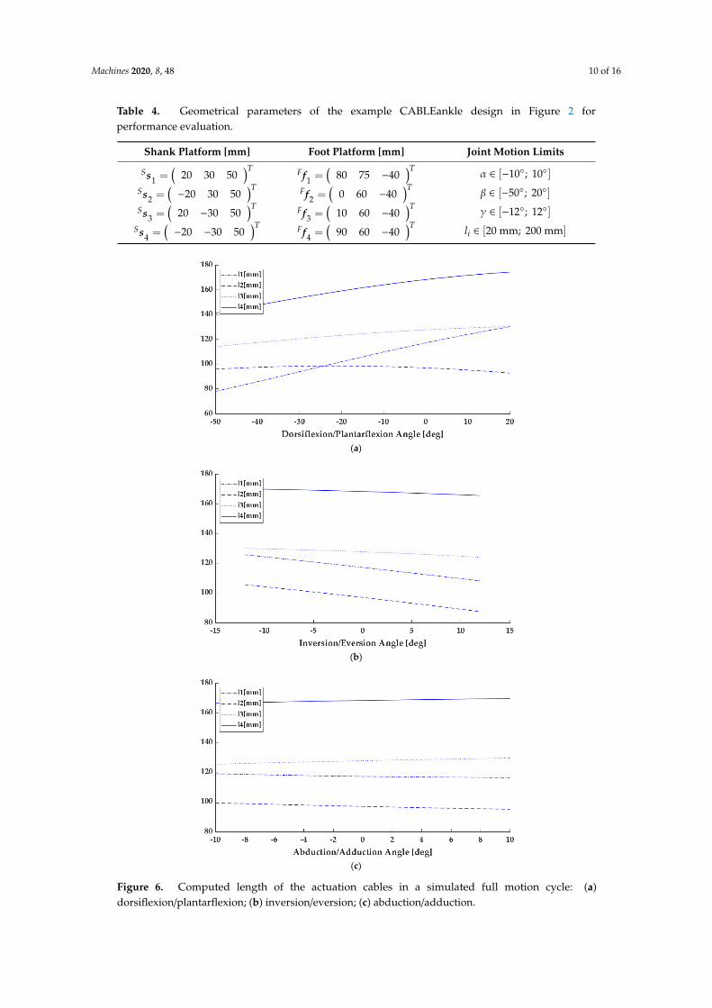
This appendix presents the formulation that is used to compute Equation (4). It is possible toformulate the input–output relations by deriving Equation (2) with respect to time, as
ωi ×Sli +
.liSui =
.x× SFRFbi (A1)
where the angular velocity of the ith cable is defined asωi, and the unit vector of the ith cable is definedas ui. The rotation matrix of the foot platform is defined as
SFR =
cαcβ cαsβsγ− sαcγ cαsβcγ+ sαsγsαcβ sαsβsγ+ cαcγ sαsβcγ− cαsγ−sβ cβsγ cβcγ
(A2)
where c stands for cosine and s for sine. By computing the scalar product of both sides of (A1) by thelimb unit vector, the dependency from the angular velocity of the ith cable is removed to get
.li =
(SFRFbi ×
Sui
)·
.x (A3)
Rewriting (A3) for each parallel limb and assembling the resulting equations in matrix form leadsto Equation (4).

Machines 2020, 8, 48 15 of 16
References
1. Knudson, D. Fundamentals of Biomechanics; Springer Science & Business Media: Heidelberg, Germany, 2007.2. Mattacola, C.G.; Dwyer, M.K. Rehabilitation of the ankle after acute sprain or chronic instability. J. Athl.
Train. 2002, 37, 413. [PubMed]3. Chen, E.T.; McInnis, K.C.; Borg-Stein, J. Ankle sprains: Evaluation, rehabilitation, and prevention. Curr.
Sports Med. Rep. 2019, 18, 217–223. [CrossRef] [PubMed]4. Zhang, M.; Davies, T.C.; Xie, S. Effectiveness of robot-assisted therapy on ankle rehabilitation—A systematic
review. J. Neuroeng. Rehabil. 2013, 10, 30. [CrossRef] [PubMed]5. Díaz, I.; Gil, J.J.; Sánchez, E. Lower-limb robotic rehabilitation: Literature review and challenges. J. Robot.
2011, 2011, 759764. [CrossRef]6. Alvarez-Perez, M.G.; Garcia-Murillo, M.A.; Cervantes-Sánchez, J.J. Robot-assisted ankle rehabilitation:
A review. Disabil. Rehabil. Assist. Technol. 2019, 15, 394–408. [CrossRef]7. Shi, B.; Chen, X.; Yue, Z.; Yin, S.; Weng, Q.; Zhang, X.; Wen, W. Wearable ankle robots in post-stroke
rehabilitation of gait: A systematic review. Front. Neurorobot. 2019, 13, 63. [CrossRef]8. Yoon, J.; Ryu, J.; Lim, K.B. Reconfigurable ankle rehabilitation robot for various exercises. J. Robot. Syst. 2006,
22, S15–S33. [CrossRef]9. Roy, A.; Krebs, H.I.; Williams, D.J.; Bever, C.T.; Forrester, L.W.; Macko, R.M.; Hogan, N. Robot-aided
neurorehabilitation: A novel robot for ankle rehabilitation. IEEE Trans. Robot. 2009, 25, 569–582. [CrossRef]10. Jamwal, P.K.; Xie, S.; Aw, K.C. Kinematic design optimization of a parallel ankle rehabilitation robot using
modified genetic algorithm. Robot. Auton. Syst. 2009, 57, 1018–1027. [CrossRef]11. Jamwal, P.K.; Hussain, S.; Ghayesh, M.H.; Rogozina, S.V. Impedance control of an intrinsically compliant
parallel ankle rehabilitation robot. IEEE Trans. Ind. Electron. 2016, 63, 3638–3647. [CrossRef]12. Saglia, J.A.; Tsagarakis, N.G.; Dai, J.S.; Caldwell, D.G. Control strategies for patient-assisted training using
the ankle rehabilitation robot (ARBOT). IEEE/ASME Trans. Mechatron. 2012, 18, 1799–1808. [CrossRef]13. Sung, E.; Slocum, A.H.; Ma, R.; Bean, J.F.; Culpepper, M.L. Design of an ankle rehabilitation device using
compliant mechanisms. J. Med. Devices 2011, 5, 011001. [CrossRef]14. Lin, C.C.; Ju, M.S.; Chen, S.M.; Pan, B.W. A specialized robot for ankle rehabilitation and evaluation. J. Med.
Biol. Eng. 2008, 28, 79–86.15. Zhang, M.; McDaid, A.; Veale, A.J.; Peng, Y.; Xie, S.Q. Adaptive trajectory tracking control of a parallel ankle
rehabilitation robot with joint-space force distribution. IEEE Access 2019, 7, 85812–85820. [CrossRef]16. Chang, T.C.; Zhang, X.D. Kinematics and reliable analysis of decoupled parallel mechanism for ankle
rehabilitation. Microelectron. Reliab. 2019, 99, 203–212. [CrossRef]17. Nurahmi, L.; Caro, S.; Solichin, M. A novel ankle rehabilitation device based on a reconfigurable 3-RPS
parallel manipulator. Mech. Mach. Theory 2019, 134, 135–150. [CrossRef]18. Cafolla, D.; Russo, M.; Carbone, G. Design and Validation of an Inherently-Safe Cable-Driven Assisting
Device. Int. J. Mech. Control 2018, 19, 23–32.19. Cafolla, D.; Russo, M.; Carbone, G. CUBE, a cable-driven device for limb rehabilitation. J. Bionic Eng. 2019,
16, 492–502. [CrossRef]20. Ceccarelli, M.; Ferrara, L.; Petuya, V. Design of a Cable-Driven Device for Elbow Rehabilitation and Exercise.
In Interdisciplinary Applications of Kinematics; Springer: Cham, Switzerland, 2019; pp. 61–68.21. Pott, A.; Bruckmann, T. (Eds.) Cable-Driven Parallel Robots: Proceedings of the 4th International Conference on
Cable-Driven Parallel Robots; Springer: Cham, Switzerland, 2019.22. Jamwal, P.K.; Aw, K.C.; Xie, S.Q.; Tsoi, Y.H. Multi-criteria optimal design of cable driven ankle rehabilitation
robot. In Mobile Robots-State of the Art in Land, Sea, Air, and Collaborative Missions; INTECH Open AccessPublisher: London, UK, 2009.
23. Shahrol, M.N.; Basah, S.N.; Basaruddin, K.S.; Ahmad, W.K.W.; Ahmad, S.A. Modelling of a Cable-drivenAnkle Rehabilitation Robot. J. Telecommun. Electron. Comput. Eng. 2018, 10, 53–59.
24. Russo, M.; Ceccarelli, M. A wearable device for ankle motion assistance. In Advances in Italian MechanismScience: Mechanisms and Machine Science 91; Springer: Cham, Switzerland, 2020; in print.
25. Brockett, C.L.; Chapman, G.J. Biomechanics of the ankle. Orthop. Trauma 2016, 30, 232–238. [CrossRef]26. Roaas, A.; Andersson, G.B. Normal range of motion of the hip, knee and ankle joints in male subjects, 30–40
years of age. Acta Orthop. Scand. 1982, 53, 205–208. [CrossRef] [PubMed]

Machines 2020, 8, 48 16 of 16
27. Hemmerich, A.; Brown, H.; Smith, S.; Marthandam, S.S.K.; Wyss, U.P. Hip, knee, and ankle kinematics ofhigh range of motion activities of daily living. J. Orthop. Res. 2006, 24, 770–781. [CrossRef] [PubMed]
28. Leirós-Rodríguez, R.; García-Soidán, J.L.; Romo-Pérez, V. Analyzing the use of accelerometers as a methodof early diagnosis of alterations in balance in elderly people: A systematic review. Sensors 2019, 19, 3883.
29. Gouttefarde, M.; Gosselin, C.M. Analysis of the wrench-closure workspace of planar parallel cable-drivenmechanisms. IEEE Trans. Robot. 2006, 22, 434–445. [CrossRef]
30. Gouttefarde, M.; Merlet, J.P.; Daney, D. Wrench-feasible workspace of parallel cable-driven mechanisms.In Proceedings of the 2007 IEEE International Conference on Robotics and Automation, Roma, Italy, 10–14April 2007; IEEE: Piscataway, NJ, USA, 2007; pp. 1492–1497.
31. Pham, C.B.; Yeo, S.H.; Yang, G.; Kurbanhuse, M.S.; Chen, I.M. Force-closure workspace analysis of cable-drivenparallel mechanisms. Mech. Mach. Theory 2006, 41, 53–69. [CrossRef]
32. Lim, W.B.; Yang, G.; Yeo, S.H.; Mustafa, S.K. A generic force-closure analysis algorithm for cable-drivenparallel manipulators. Mech. Mach. Theory 2011, 46, 1265–1275. [CrossRef]
33. Russo, M.; Ceccarelli, M. Device for Ankle Motion Assistance. Italian Patent 102020000002863, 13February 2020.
© 2020 by the authors. Licensee MDPI, Basel, Switzerland. This article is an open accessarticle distributed under the terms and conditions of the Creative Commons Attribution(CC BY) license (http://creativecommons.org/licenses/by/4.0/).