Analysis, Modeling and Control Design of a Synchronous Generator … · · 2015-07-10Synchronous...
15
1 Analysis, Modeling and Control Design of a Synchronous Generator with a Wind Turbine and a Multilevel Voltage Source Inverter Walid Emar Faculty of Engineering, Electrical Department Isra University, Amman, 11622, Jordan International Journal of Research in Electrical & Electronics Engineering Volume 3, Issue 3, July-September, 2015, pp. 01-15 ISSN Online: 2347-5439 Print: 2348-0025, DOA: 11042015 © IASTER 2015, www.iaster.com ABSTRACT This paper focuses on the analysis, modeling and control of a wind turbine permanent magnet synchronous generator system. It deals with the field oriented control of the speed of the generator and with the PI control of its torque independently. The voltage setup up regulation is also done by a simple dc-dc converter. Different operating conditions just like step variation in the turbine speed and variable driving torque are investigated to eliminate the influence of the variable wind and turbine speeds on the speed and power of the generator. The result is a progressive improvement in the dynamic behavior of the generator and consequently a good energy efficiency of the overall system and a complete suppress of the influence of the variation in the turbine speed on the speed of the generator. Furthermore, it introduces a new topology of the voltage source inverter (VSI) known as a multilevel VSI. The result of using such inverter is the increase in the output power, the reduction in the harmonic content at the system output, and finally, it resulted in a stable system with frequency synchronization between the load and the turbine. The results are then verified in the environment of Simplorer. Keywords: Permanent Magnet Synchronous Generator (PMSG), Wind Turbine, Field Oriented Control, and Multilevel Three Phase Inverter. 1. INTRODUCTION The rapid development and improvement in the renewable energy systems has helped the increasing prosperity of the wind energy systems thus to be widely used all over the world for generating electricity [2]. Wind energy is unfailing and tireless renewable energy system and its environmental impact factor is very low as compared to other energy sources. The installation of such systems may be expensive but they have a net energy gain because they produce more energy than is consumed to implement the system. Furthermore, their cost decreases with the increasing number of individual turbine units per area [3]. Wind turbine is different from other energy sources since it is simply used to extract the energy from the wind. It requires a special installation and design of its blades to capture the wind's energy from the wind, and to keep it within adjustable speed and to point the turbine into the most favorable orientation of the wind [3]. One of the most effective methods used to control the speed and the torque of wind turbine with a permanent magnet generator is the field oriented control. It is a closed loop control strategy consisting
Transcript of Analysis, Modeling and Control Design of a Synchronous Generator … · · 2015-07-10Synchronous...

1
Analysis, Modeling and Control Design of a Synchronous Generator with a Wind Turbine and a
Multilevel Voltage Source Inverter
Walid Emar Faculty of Engineering, Electrical Department
Isra University, Amman, 11622, Jordan
International Journal of Research in Electrical & Electronics Engineering Volume 3, Issue 3, July-September, 2015, pp. 01-15
ISSN Online: 2347-5439 Print: 2348-0025, DOA: 11042015 © IASTER 2015, www.iaster.com
ABSTRACT This paper focuses on the analysis, modeling and control of a wind turbine permanent magnet synchronous generator system. It deals with the field oriented control of the speed of the generator and with the PI control of its torque independently. The voltage setup up regulation is also done by a simple dc-dc converter. Different operating conditions just like step variation in the turbine speed and variable driving torque are investigated to eliminate the influence of the variable wind and turbine speeds on the speed and power of the generator. The result is a progressive improvement in the dynamic behavior of the generator and consequently a good energy efficiency of the overall system and a complete suppress of the influence of the variation in the turbine speed on the speed of the generator. Furthermore, it introduces a new topology of the voltage source inverter (VSI) known as a multilevel VSI. The result of using such inverter is the increase in the output power, the reduction in the harmonic content at the system output, and finally, it resulted in a stable system with frequency synchronization between the load and the turbine. The results are then verified in the environment of Simplorer. Keywords: Permanent Magnet Synchronous Generator (PMSG), Wind Turbine, Field Oriented Control, and Multilevel Three Phase Inverter.
1. INTRODUCTION
The rapid development and improvement in the renewable energy systems has helped the increasing prosperity of the wind energy systems thus to be widely used all over the world for generating electricity [2]. Wind energy is unfailing and tireless renewable energy system and its environmental impact factor is very low as compared to other energy sources. The installation of such systems may be expensive but they have a net energy gain because they produce more energy than is consumed to implement the system. Furthermore, their cost decreases with the increasing number of individual turbine units per area [3]. Wind turbine is different from other energy sources since it is simply used to extract the energy from the wind. It requires a special installation and design of its blades to capture the wind's energy from the wind, and to keep it within adjustable speed and to point the turbine into the most favorable orientation of the wind [3].
One of the most effective methods used to control the speed and the torque of wind turbine with a permanent magnet generator is the field oriented control. It is a closed loop control strategy consisting
International Journal of Research in Electrical & Electronics Engineering Volume-3, Issue-2, April-June, 2015, www.iaster.com ISSN (O) 2347-5439
(P) 2348-0025
2
of two controllers, an inner current loop controller and an outer current loop controller, one for controlling the speed of the rotor of the generator and the other for controlling the torque of the generator and consequently the power from the generator [4].
Another one of the biggest challenges that concern the wind turbine systems is how to connect the frequency variable wind turbine to constant frequency grid of 50/60 Hz. Using gearboxes with a synchronous generator increases the audible noise, frequently requires a usual maintenance of the system and their components are costly expensive. The rapid increase in the development of power electronic converters has introduced new methods of connecting variable frequency wind turbines with the generator to constant frequency a.c. grid or load through variable frequency power electronic converters with dc links. This helps adjusting the frequency of the generator and its speed independently and decreasing the difference between the output and the input powers to acceptable limits which results in a stable system. Furthermore, they are less noisy than gearboxes [3-4].
This paper focuses on the control strategy of a wind turbine and synchronous generator supplying an a.c. load through a multilevel three phase voltage source inverter (VSI). The output voltage from the PMSG is first rectified within a three phase bridge rectifier and its torque is controlled using a dc-dc converter [11, 14]. The power of the rotor is adjusted by controlling the torque and the speed of the generator as mentioned previously. To avoid any magnetic saturation in the overall system the voltage at the dc side of the inverter is adjusted using the dc-dc converter simultaneously with the frequency of the load which is controlled using the multilevel three phase VSI. The overall system is analyzed and simulated for constant and variable wind turbine speeds with constant and variable power coefficient and pitch angle for the turbine blades. In the rest of this paper, it is also presented the averaged model for the three-level VSI in αβ and dq-frames.
2. DEVELOPMENT OF THE SYSTEM MODEL’S EQUATIONS AND EQUIVALENT CIRCUIT
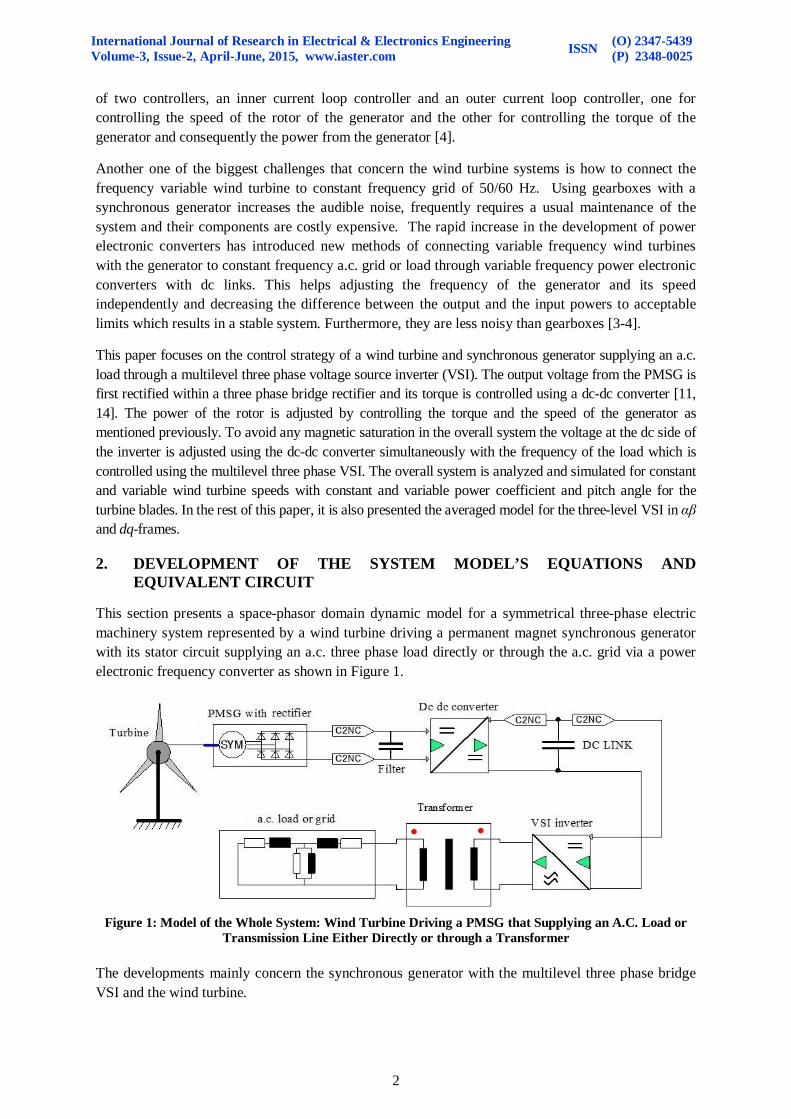
This section presents a space-phasor domain dynamic model for a symmetrical three-phase electric machinery system represented by a wind turbine driving a permanent magnet synchronous generator with its stator circuit supplying an a.c. three phase load directly or through the a.c. grid via a power electronic frequency converter as shown in Figure 1.
Figure 1: Model of the Whole System: Wind Turbine Driving a PMSG that Supplying an A.C. Load or
Transmission Line Either Directly or through a Transformer The developments mainly concern the synchronous generator with the multilevel three phase bridge VSI and the wind turbine.
International Journal of Research in Electrical & Electronics Engineering Volume-3, Issue-2, April-June, 2015, www.iaster.com ISSN (O) 2347-5439
(P) 2348-0025
3
2.1. Mathematical Model of a Synchronous Generator
The model simulated in this paper is a three-phase permanent magnet synchronous machine which is a type of dc current brushless machine. On the contrary of separately excited synchronous machines, the permanent magnet excitation field of this machine cannot be changed. The excitation of such machine could be affected by the internal voltage generated in the stator circuit by permanent magnets of the rotor during the operation under rated conditions. All other machine parameters are actual quantities, referring to the values in volts, amperes, ohms, and they are listed in the following table [2, 7]:
Table 1: Actual Parameter of the Designed PMSG in this Paper Name of a parameter: Symbol Actual value Stator resistance: Rs 1Ω Stator inductance (direct axis): Ld 75mH Stator inductance (quadrature axis): Lq 75mH Number of poles: p 24 Nominal frequency: fn 8Hz Nominal field e.m.f: Up 240V Zero component resistance: R0 925.8mΩ Zero component inductance: L0 58.4mH
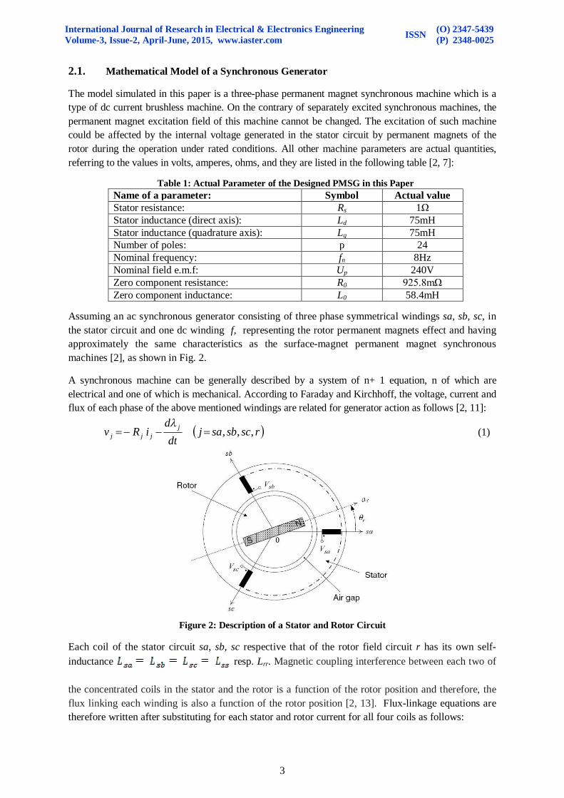
Assuming an ac synchronous generator consisting of three phase symmetrical windings sa, sb, sc, in the stator circuit and one dc winding f, representing the rotor permanent magnets effect and having approximately the same characteristics as the surface-magnet permanent magnet synchronous machines [2], as shown in Fig. 2.
A synchronous machine can be generally described by a system of n+ 1 equation, n of which are electrical and one of which is mechanical. According to Faraday and Kirchhoff, the voltage, current and flux of each phase of the above mentioned windings are related for generator action as follows [2, 11]:
rscsbsajdt
diRv j
jjj ,,,
(1)
Figure 2: Description of a Stator and Rotor Circuit
Each coil of the stator circuit sa, sb, sc respective that of the rotor field circuit r has its own self-inductance resp. Lrr. Magnetic coupling interference between each two of
the concentrated coils in the stator and the rotor is a function of the rotor position and therefore, the flux linking each winding is also a function of the rotor position [2, 13]. Flux-linkage equations are therefore written after substituting for each stator and rotor current for all four coils as follows:

International Journal of Research in Electrical & Electronics Engineering Volume-3, Issue-2, April-June, 2015, www.iaster.com ISSN (O) 2347-5439
(P) 2348-0025
4
(2)
Where Mss is the mutual inductance between each adjacent pair of the concentrated coils in the stator circuit. Mad, Mbd, Mcd and Mrd are mutual inductances between stator and rotor coils with respect to the damper winding. The current through damper winding d is id [2, 8]. Let's assume that the rotor under steady state conditions rotates at constant angular velocity ωr, so that for the two-pole generator:
(3)
The initial position of the rotor winding is given by the angle θo, which can be arbitrarily chosen at .0t Hence, the stator coil voltages constitute three phase set of emfs which give rise to balanced
three phase line currents, say [2]:
(4)
Where Im is the maximum value of the stator currents and α is the phase angles of lag of the stator currents (isa , isb, isc) with respect to the stator voltages. The effect of the damper winding may be neglected without causing a serious error in the machine analysis [2, 14].
(5) The expressions for the fluxes linked by the stator may be simplified as:
(6)
Where λrm is the maximum flux of the rotor. In terms of rotating phasors (space vector) and after using the Euler’s identity, it yields: (7)
To develop an equivalent circuit for the permanent magnet synchronous generator (PMSG), we substitute for λs from (7) in (1). Thus,

International Journal of Research in Electrical & Electronics Engineering Volume-3, Issue-2, April-June, 2015, www.iaster.com ISSN (O) 2347-5439
(P) 2348-0025
5
(8)
Where τe is the electromagnetic torque of the synchronous generator. In the equations all bolded letters are vectors with their belonging elements.
Figure 3: Space Vector Domain Equivalent Circuit of the PMSG
Based on (8), the equivalent circuit of Figure 3 can be sketched for the PMSG. This equivalent circuit is valid for both steady-state and dynamic conditions.
2.2. Dynamic and Steady-State Model of a Multilevel Three Phase Bridge Voltage Source Inverter (VSI) with Natural Sampling
This section introduces a topology of variable frequency voltage source inverter (VSI) systems. A variable frequency VSI system establishes the basic foundation for the electromechanical energy conversion system in which the a.c. side of the VSI is hooked up with the stator terminals of the synchronous generator. 2.2.1. Principle of Operation of a Multilevel Three Phase Bridge Voltage Source Inverter (VSI)
with Natural Sampling
The circuit configuration of the multilevel three phase inverter usually consists of three modules, known as half bridge switch cells (phases) as shown in Figure 4. Each one of these cells is divided into two halves, and the regulated dc voltage at the input of the inverter is divided equally between the flying capacitors C1, C2 at the input of the inverter. The midpoint neutral, 0, is connected to the multilevel VSI via the clamp diodes D1, D2, D3, D4, D5 and D6. All voltages in Figure 4 are expressed with reference to the midpoint neutral. The switching function for each module is defined as:
Figure 4: Schematic Diagram of the Multilevel Three Phase Bridge VSI

International Journal of Research in Electrical & Electronics Engineering Volume-3, Issue-2, April-June, 2015, www.iaster.com ISSN (O) 2347-5439
(P) 2348-0025
6
It is also required that the triggering signals for switches Q42 and Q41 must be compatible, that is, 14111 GG . Similarly, the gating signals for Q12 and Q14 are compatible, that is, 11412 GG [1].
PWM Switching Strategy for Multilevel VSI
Table 2: Switching Diagram of One Phase
Table 2 illustrates the switching strategy for one phase. The switching regime of each phase in a three-level VSI can be divided into twelve states. The a.c. side terminal voltage generated at the output of each half bridge VSI switch cell is then governed by the following equation:
(9)
Thus, the three phase voltages will be determined as: , , (10)
Thus, to generate a set of three phase balanced voltages at the a.c. side, the modulating signal mabc should also be defined as a set of balanced three phase sinusoidal time functions with the required amplitude, phase angle, and frequency. It is usually the output of a closed-loop control system that regulates iabc. In general, it may have the following form [5]:
(11)
Where ε(t) contains the phase angle and frequency information. In a.c. systems, it is also required to exercise fast changes in the amplitude and/or the phase angle of the a.c. side terminal voltage using the techniques presented in [1, 5], based on the concepts of space phasor, αβ-frame, or dq-frame. 3. dq-FRAME REPRESENTATION AND CONTROL OF THREE-PHASE
SYSTEMS
The model developed for the synchronous generator in [2] is very good for steady state operation. However, for normal operation under steady state conditions with transient conditions taken into account two-axis qd model is required. The two-axis model usually used for vector control design of PMSG can be obtained by using the space vector theory. Complex space vectors can be described using only two orthogonal axes. The generator can be considered as a 2-phase machine. The utilization of the 2-phase generator model reduces the number of equations and simplifies the control design [10, 12].
3.1. Space Vector Definition
In this paper the two-axis model is introduced by the means of the equations of the salient pole generator which have more pole pair and whereas the largest generating units are the wind and hydroelectric turbines. These turbines usually run at lower speed to avoid any damage due to
Switching Status of Individual Switches in Phase A
Gating
signals
G11 1 0 0 G42 1 1 0 G41 0 1 1 G12 0 0 1
midpoint voltage, Vt Vdc 0 -Vdc
Switching state 1 0 -1

International Journal of Research in Electrical & Electronics Engineering Volume-3, Issue-2, April-June, 2015, www.iaster.com ISSN (O) 2347-5439
(P) 2348-0025
7
centrifugal forces. Such three phase machine has three symmetrically distributed windings in the stator circuit and two or more pole permanent magnets in the rotor circuit that produces a sinusoidally changing magnetic field around the airgap. Assuming that isa , isb , and isc are the instantaneous balanced 3-phase stator currents, then: (12)
The resulting stator current space vector is given as: (13)
Where the two variables is and is representing the real and imaginary part of the stator current space vector which are denoted as Clerk's transformation. The control in the two-axis frame helps reducing the number of required controllers from three to two. However, the reference, feedback, and feed-forward signals are in general sinusoidal functions of time. Therefore, to achieve a satisfactory performance and small steady-state errors especially for a variable frequency operating system, the dq-frame based control introduces a solution to this problem [1, 5]. The αβ to dq frame transformation is given as:
(14)
Figure 5: Representation of a Two-Axis Frame of a Salient Pole PMSG with a Permanent Magnet Rotor
Where id and iq are the direct-axis and quadrature axis components of the stator space current and ɛ(t) is a phase shift in the space phasor current is shown in Figure 5. A direct transformation from the abc frame to the dq frame can be as follows:
(15)
Equation (14) and (15) can be used to transform a set of abc frame equations to an equivalent set of equations in dq frame.
3.1.1. dq Frame Model of a synchronous generator
The vector control strategy is also applicable to a synchronous machine [5-8]. However, in the case of a synchronous machine, to decouple the machine flux and torque, ɛ(t) is chosen to be equal to the rotor electrical angle, which can be obtained from a shaft encoder or through an estimation process [2]. Under the condition of neglected asymmetry of stator windings of the generator, the mathematical model of the synchronous generator may be described as follows:

International Journal of Research in Electrical & Electronics Engineering Volume-3, Issue-2, April-June, 2015, www.iaster.com ISSN (O) 2347-5439
(P) 2348-0025
8
(16)
Therefore, the dynamic model which describes the behavior of the synchronous generator in the synchronously rotating dq-reference frame can be expressed as follows:
(17)
Where the vd and vq are d-axis and q-axis terminal voltages, respectively. The id and iq are, respectively, d-axis and q-axis torque producing currents. The Ld and Lq are the d-axis and q-axis magnetizing inductances, respectively. The Rs is the stator resistance and ωr is the angular speed of the rotor. The developed electromagnetic torque is given as: (18)
Concerning the mutual flux equations, they may be given as follows:
(19)
Where λm is the flux linkage produced by the permanent magnet PMSG. This mathematical model obtained for the permanent magnet synchronous generator is implemented in Simplorer and Matlab/Simulink [3, 5]. The electromechanical parameters of the generator are mentioned in Table 1. The simulation is done under a condition of variable driving torque and constant reference speed or constant driving torque of the generator and variable reference speed.
Figure 6 compares between the stator voltages, currents, speed and torque under above mentioned conditions. In this Figure it is shown that the PMSG has a higher output voltage at higher speed and torque. So far, the concept, the model, the analysis and the simulation of the PMSG with the three-level VSI have been derived and made. The simulation shows that the selected systems work correctly and therefore, the control strategy and design of controllers could be done.
PMSG phase output currents for constant reference speed and variable torque
PMSG.Is_1 PMSG.Is_2 PMSG.Is_3
t [s]
4.00e+002
-3.00e+002
0
-2.00e+002
2.00e+002
0 1.00200.00m 400.00m 600.00m 800.00m
P...P...P...t [s]
1.50e+001
-1.50e+001
0
350.00m 500.00m425.00 m
PMSG phase output currents for variable reference speed and variable torque
PMSG.Is_1 PMSG.Is_2 PMSG.Is_3
t [s]
2.00e+002
-2.00e+002
0
-1.00e+002
1.00e+002
0 1.00200.00m 400.00m 600.00m 800.00m
P...P...P...t [s]
1.50e+002
-2.00e+002
0
350.00m 500.00m425.00 m
PMSG speed with constant reference speed and variable torque
PMSG.N n_ref.VAL
t [s]
8.00e+001
0
2.00e+001
4.00e+001
6.00e+001
0 1.00200.00m 400.00m 600.00m 800.00m
PMSG speed with variable reference speed and variable torque
PMSG.N n_ref.VAL
t [s]
7.00e+001
0
2.00e+001
4.00e+001
6.00e+001
0 1.00200.00m 400.00m 600.00m 800.00m

International Journal of Research in Electrical & Electronics Engineering Volume-3, Issue-2, April-June, 2015, www.iaster.com ISSN (O) 2347-5439
(P) 2348-0025
9
PMSG d_axis and q_axis currents for constant reference speed and variable torque
PMSG.Is_d PMSG.Is_q torque.VAL
t [s]
6.00e+002
-1.00e+0020
2.00e+002
4.00e+002
0 1.00200.00m 400.00m 600.00m 800.00m
PMSG d_axis and q_axis currents for variable reference speed and variable torque
PMSG.Is_d PMSG.Is_q torque.VAL
t [s]
6.00e+002
-1.00e+0020
2.00e+002
4.00e+002
0 1.00200.00m 400.00m 600.00m 800.00m PMSG line to line output voltages for variable reference speed and variable torque
PMSG.Us_12 PMSG.Us_23
t [s]
8.00e+003
-8.00e+003
0
-5.00e+003
5.00e+003
0 1.00200.00m 400.00m 600.00m 800.00m
P...P...
t [s]
6.00e+003
-6.00e+003
0
350.00 m 500.00 m425.00 m
PMSG line to line output voltages for variable reference speed and variable torque
PMSG.Us_12 PMSG.Us_23
t [s]
1.00e+004
-7.50e+003
0
-5.00e+003
5.00e+003
0 2.00500.00m 1.00 1.50
P...P...
t [s]
3.00e+003
-3.00e+003
0
1.90 2.001.94 1.96
(a) (b)
FIGURE 6: Experimental comparison between PMSG output currents, voltages and speed under the condition of: a) constant reference speed and variable driving torque, b) variable reference speed and
variable driving torque.
4. Wind Turbine System Structure
The turbine used in this paper is a vertical axis turbine having a rated power of 3.6MW and a blade diameter of 104m. The rated speed of this turbine is about 16m/s and it has a moment of inertia about 0.4×10⁶ kg.m2.
Figure 7: Cp Versus Λ Curve For Wind Turbine
The principle of operation of such system is that the power-electronic conversion system controls the frequency of the stator circuit to produce a variable speed in the rotor. Operation of a wind turbine can be characterized by its mechanical power, as given by [3-4, 9]: (20)
Where is the swept area of the turbine (m2) with r the radius of each its blade, V is the linear velocity of the wind (m/s), ρ is air density (kg/m3) and Cp is known as Betz Limit or power coefficient.

International Journal of Research in Electrical & Electronics Engineering Volume-3, Issue-2, April-June, 2015, www.iaster.com ISSN (O) 2347-5439
(P) 2348-0025
10
All other terms in Eq. 20 are constants except Cp which is unique to different types of turbines and it depends on the wind speed that the turbine works in and varies with the tip speed ratio of the turbine. The tip speed ratio, λ is defined as the ratio of the blade tip speed to the wind speed. The blade tip speed is given as:
(21)
Where nt is the rotational speed of turbine (rpm) and r is the radius of its blade. Using Figure 7 acceptable for most wind turbines and having background information about the turbine mechanical features, the conditions in which the turbine works, then analytical calculations may be done to find how much energy the turbine could produce as it is shown [8-10].
Since it is required to produce a maximum power from the turbine at lower speed than the rated speed, the blades angles are adjusted by a feedback mechanism with a special control strategy for maximum power point tracking [6, 7].
In order to achieve the best performance of the turbine, the pitch angle of the turbine is chosen as unity and the reference speed of the generator's rotor should be given as:
(22)
In the low speed region the tip speed ratio λ is chosen to be constant. lblade is the length of the turbine blades.
5. CONTROL STRATEGY OF THE TURBINE-PMSG WHOLE SYSTEM
The field oriented control used in this paper depends on converting the speed dependent system into a two dimensional dq time invariant system. Thus, the input power to the wind turbine and the driving torque produced should be controlled as the wind speed changes. This is usually done by using the pitch control which is used to increase the power at low wind speed and consequently the torque driving the generator with the q-axis component of the stator current.
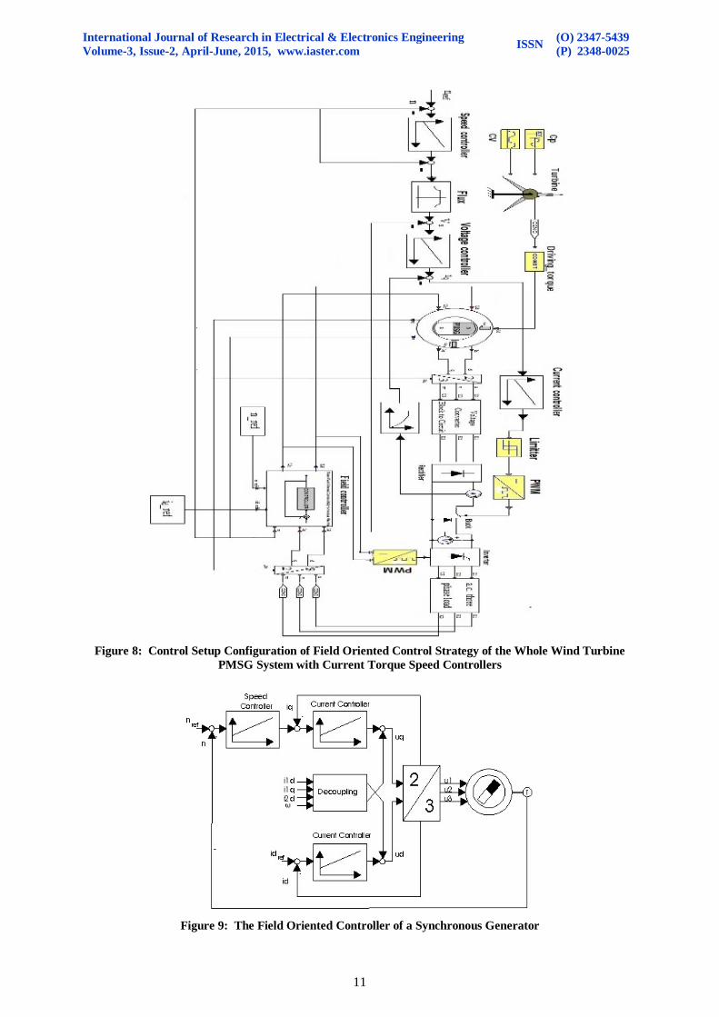
Above rated speed of the wind, the aerodynamic power generated by the rotor of the turbine should be kept at its rated value, and therefore, the torque and its corresponding q-axis current component should be adjusted to achieve this requirement [3, 12]. At nominal speeds, everything is kept constant as it is. The control schematic diagram of the whole system is shown in Figure 9.
5.1. Torque and speed Control
Field oriented control depends on controlling the two stator current components, the q-axis component associated with the torque and the d-axis component aligned with the flux, therefore it requires two PI controllers, one for torque and the other one for the speed and power or voltage. Exact design of speed and torque controller is done in [3, 8, 10].
The quantities included in this control process are the dc voltage, Vs at the dc side of VSI, the dc output current of the rectifier, the three phase stator current and the PMSG rotor actual speed and position.
In the first place the reference speed of the generator is determined and then it is fed back to be compared with the actual speed of the rotor. The speed difference is applied to a speed controller working on making this speed error equal to zero. Consequently, the speed controller generates the required reference voltage at the output of the dc-dc converter. The voltage difference (error) between this reference voltage and the actual output voltage of the converter is applied to a PI current controller which in turn calculates the reference input current for the converter.
International Journal of Research in Electrical & Electronics Engineering Volume-3, Issue-2, April-June, 2015, www.iaster.com ISSN (O) 2347-5439
(P) 2348-0025
11
Figure 8: Control Setup Configuration of Field Oriented Control Strategy of the Whole Wind Turbine
PMSG System with Current Torque Speed Controllers
Figure 9: The Field Oriented Controller of a Synchronous Generator

International Journal of Research in Electrical & Electronics Engineering Volume-3, Issue-2, April-June, 2015, www.iaster.com ISSN (O) 2347-5439
(P) 2348-0025
12
At the same time the three phase stator current of PMSG are transformed from the three dimensional system into two dimensional dq current components, one for controlling the flux and the speed of the generator and the other for controlling the torque and the power from the generator. They are applied to a special field controller shown in Figure 9 which is used to generate the conduction angles for VSI and the required dq voltage components for PMSG. 6. SIMULATION AND RESULTS
The overall system described previously is simulated in the environment of Simplorer 7 under different operating conditions just to study its dynamic characteristics and behavior.
Generator's rotor speed (rpm)PMSG.N
t [s]
5.00e+001
-2.00e+001
0
2.00e+001
0 3.001.00 2.00
Speed of turbine (rpm)Turbine.S...
t [s ]
5.00e+001
-2.00e+001
0
2.00e+001
0 3.001.00 2.00 Load phase vol tage
vsa.V [V]
t [s]
3.00e+002
-3.00e+002
0
2.90 3.002.92 2.94 2.96 2.98
VSI output currents = load phase currentsisa.I [A] isb.I [A] isc.I [A]
t [s]
3.00e+001
-3.00e+001
0
2.90 3.002.92 2.94 2.96 2.98 Generator d-axis reference (green) and q-axis (red) phase v oltage components
PMSG.Is_d PMSG.Is_q
t [s ]
2.00e+002
-1.25e+002
0
1.00e+002
0 3.001.00 2.00
PMS...PMS...
t [s ]
0
-1.20e+0022.90 3.002.94 2.96
Generator d-axis ref erence (red) and q-axis (green) phase v oltage componentsPMSG.Us_d PMSG.Us_q
t [s ]
1.00e+003
-1.00e+002
2.00e+002
4.00e+002
6.00e+002
8.00e+002
0 3.001.00 2.00
S teady state view-Generator d-axis reference (red) and q-axis (green) pha...P MS G....P MS G....
t [s]
4.00e+002
-1.00e+002
1.00e+002
2.90 3.002.92 2.94 2.96 2.98
Figure 10: Experimental Comparison of Field Oriented Control Waveforms
of the Generator with an RL Load
Speed of turbineTurbine.S...
t [s ]
5.00e+001
-1.00e+001
2.00e+001
0 3.001.00 2.00
Generator's rotor speedPMSG.N
t [s]
5.00e+001
-1.00e+001
2.00e+001
0 3.001.00 2.00

International Journal of Research in Electrical & Electronics Engineering Volume-3, Issue-2, April-June, 2015, www.iaster.com ISSN (O) 2347-5439
(P) 2348-0025
13
Load phase vol tagevsa.V [V]
t [s]
1.50e+002
-1.50e+002
0
2.90 3.002.92 2.94 2.96 2.98
VSI output currents = load phase currentsisa.I [A] isb.I [A] isc.I [A]
t [s]
2.00e+002
-2.00e+002
0
-1.00e+002
1.00e+002
2.90 3.002.92 2.94 2.96 2.98 Generator d-axis ref erence (red) and q-axis (green) phase voltage components
PMSG.Us_d PMSG.Us_q
t [s]
1.00e+003
-2.00e+002
0
2.50e+002
5.00e+002
7.50e+002
0 3.001.00 2.00
S teady state view-Generator d-axis reference (red) and q-axis (green) pha...PMSG....PMSG....
t [s]
2.50e+002
-5.00e+001
1.00e+002
2.90 3.002.92 2.94 2.96 2.98
Generator d-axis ref erence (green) and q-axis (red) phase v oltage componentsPMSG.Is_d PMSG.Is_q
t [s]
2.00e+002
-1.20e+002
0
1.00e+002
0 3.001.00 2.00
Drehmoment11 PMSG...PMSG...
t [s ]
2.00e+001
-1.20e+002
-5.00e+001
2.90 3.002.92 2 .94 2.96 2.98
Figure 11: Experimental Comparison of Field Oriented Control Waveforms of the Generator
with a Type of Load of A.C. Long Transmission Line
At first the system supplying two different types of a.c. load (RL load or a model representing a long transmission line with all its features and parameters) is subjected to a constant current velocity of the turbine medium, CV=12m/s.
Generator d-axis ref erence (red) and q-axis (green) phase v oltage comp...
PMSG...PMSG...
t [s]
8.00e+001
-2.00e+001
0
2.00e+001
4.00e+001
6.00e+001
0 5.001.00 2.00 3.00 4.00
d-axis component aloneP...
t...
4.00e+001
-2.00e+001
0
2.00e+001
0 5.001.00 3.00
VSI output currents = load phase currents
isa.I [A] isb.I [A] isc.I [A]
t [s]
1.50e+000
-1.50e+000
0
-1.00e+000
1.00e+000
1.90 2.151.95 2.00 2.05 2.10 Phase load voltage
vsa.V [...
t [s]
1.00e+002
-1.00e+002
0
-5.00e+001
5.00e+001
1.90 2.151.95 2.00 2.05 2.10
Generator's rotor actual speed (v iolet) with its ref erence speed (rpm)
PMSG.n n_ref .VAL
t [s]
8.00e+001
-2.00e+001
0
2.00e+001
4.00e+001
6.00e+001
0 5.001.00 2.00 3.00 4.00 Speed of turbine (rpm)
Turbin...
t [s]
6.00e+001
-1.00e+001
2.00e+001
4.00e+001
0 5.001.00 2.00 3.00 4.00
Generator d-axis (v iolet) and q-axis (blue) phase v oltage components f rom the Field controller
100 * F ield_C...Field_Control...
t [s]
2.00e+003
-2.50e+002
5.00e+002
1.00e+003
1.50e+003
0 5.001.00 2.00 3.00 4.00
Figure 12: Transient Behavior of the Generator with a Type of RL Load Under the Condition of Variable Reference Speed of the Generator and Variable Speed of Turbine At T=1s.
International Journal of Research in Electrical & Electronics Engineering Volume-3, Issue-2, April-June, 2015, www.iaster.com ISSN (O) 2347-5439
(P) 2348-0025
14
The load is considered to be a three phase a.c. RL load representing the simple equivalent circuit of an induction motor (R=2Ω, L=5mH). Then the load is chosen to be the equivalent circuit of a three phase long transmission line representing the a.c. grid with the following parameters: series impedance (R=0.05Ω, L=2mH) and shunt admittance consisting of phase to neutral capacitances (Cu=Cv=Cw=10μF) in series with resistance (Ru=Rv=Rw=200mΩ) and line capacitance (C12=C13=C23=5μF). Furthermore, the performance of the system is examined by subjecting the system to fluctuations and step changes in the wind or turbine speed and in the reference speed of the generator as shown in Figure 12. The load is again considered to be an a.c. RL load (R=50Ω, L=100mH). 7. CONCLUSION The dynamic behavior of a permanent magnet synchronous generator driven by a wind turbine and supplies an a.c. load or grid has been investigated under differently variable turbine speed and driving torque operating conditions. This paper focuses on controlling the torque and the speed of the generator and on matching its speed with the speed of the wind turbine just to get the best performance of the overall system. As illustrated in the Figures above the whole system with its control block diagram including the current, speed and field controllers are working as good as it is required. The measured generator and turbine speeds are compared together and at the same time the dq measured currents and voltages of the generator are compared with the reference ones as shown in all simulated Figures above. The voltage at the dc side of the rectifier and the inverter has been controlled independently using PI voltage and current controllers as shown in Figure 8. This decreased the ripple in them and kept it within the required limits which helped in improving the performance of the overall system as shown in the Figures. The parameters of the PI controllers were chosen using the method of trial and error while the parameters of the field controller may be given as a result of analytical calculations demonstrated in [3-4]. For further improvement of the voltage and current waveforms at the dc side of the inverter an additional low pass filter circuit is used. These filters consist of Cf=2000μF with Lf=10mH at the output of the rectifier and L1= 1mH with C1=C2=5mF at the dc side of the inverter. As Figures 10, 11, 12 indicate the results obtained accurately predict the good dynamic behavior of the system and that the waveforms obtained from the averaged model shown in Figure 9 are comparable to those in Figures 6 obtained for the switched system in Figure 4. From Figures 10, 11 and 12 it is also evident that the equity and matching between the turbine speed and the generator speed is achieved which may also result in the equity between the input power of the generator and its output power. Thus, the field oriented control of the speed implemented in this paper gives good results since when the machine is loaded and the reference speed is changed in steps the VSI output currents increase due to the good control of the load voltages and currents. The speed of the generator follows exactly the reference speed in all cases demonstrated in this paper. Further study may be done on different types of generator topologies to find out which topology is better to operate with a wind turbine system.

International Journal of Research in Electrical & Electronics Engineering Volume-3, Issue-2, April-June, 2015, www.iaster.com ISSN (O) 2347-5439
(P) 2348-0025
15
REFERENCES
[1] Amirnaser Yazdani, Reza Iravani: Voltage Sourced Converters in Power Systems, Modeling, Control and Applications, IEEE press, John Wiley & Sons, Inc., 2010.
[2] John J. Grainger, William D. Stevenson, Jr.: Power System Analysis, Department of Electrical And Computer Engineering, North Carolina State University, McGraw-Hill, Inc., 1994.
[3] Nima Madani: Design of a Permanent Magnet Synchronous Generator for a Vertical Axis Wind Turbine, Master of Science Thesis in Electrical Machines and Power Electronics at the School of Electrical Engineering Royal Institute of Technology Stockholm, Sweden, June 2011.
[4] Johan Bjork-Svensson And Jose Oscar Munoz Pascual: Torque Control of a Wind Turbine Using 6-Phase Synchronous Generator and a Dc/Dc Converter, Department of Energy and Environment, Chalmers University of Technology, Goteborg, Sweden 2007.
[5] Abd Almula G. M. Gebreel: Simulation and Implementation of Two Level and Three Level Inverters By Matlab and RT-Lab, thesis, Presented in Partial Fulfillment of the Requirements for the Degree Master of Science in the Graduate School of The Ohio State University, The Ohio State University 2011.
[6] Mohan S., Güldner H., Wolf H: State Feedback Controller for a Three Phase PWM Voltage Source Inverter. Actapress, European power and energy systems: 2004.
[7] Andreea Cimpoeru: Encoderless Vector Control of PMSG for Wind Turbine Applications, Master thesis, PED 1035, Institute of Energy Technology, Aalborg University, 2010.
[8] Ivan Jadrich: Modeling and Control of a Synchronous Generator with Electronic Load, Master thesis, Virginia Polytechnic Institute and State University, 1998.
[9] Arkadiusz Kulka: Pitch and Torque Control of Variable Speed Wind Turbines, Chalmers University, Sweden, 2004.
[10] P. K. Goel S. S. Murthy, B. Singh and S. K. Tiwari: A Comparative Study of Fixed Speed and Variable Speed Wind Energy Conversion Systems Feeding the Grid. In Int. Conf. on PEDS, pages 736–743, 2007.
[11] Tin Win Mon, Myo Myint Aung: Simulation of Synchronous Machine in Stability Study for Power System, World Academy of Science, Engineering and Technology 39 2008.
[12] Harnefors, L.: Control of Variable-Speed Drives, Malardalen University, 2002.
[13] Kumar S., Umamaheswari B: Simultaneous Control of Torque and Rotor Power Extraction on SPSM Using DTC Technique. Actapress, International Journal of Modelling And Simulation 2009; 29 (3).
[14] Chattopadhyay S., Ramanarayanan V. A Voltage-Sensorless Control Method to Balance the Input Currents of a Three-Wire Boost Rectifier under Unbalanced Voltage Condition. IEEE Trans. Ind. Electron. IE-52: 386–398, 2005.