Retrofit Measures for Abutments Footings and Abutments, Footings ...

Types of Structures & Loads-Page 1 of 21
ENGR. ATIQ UR REHMAN AWAN
STRUCTURAL
ANALYSIS
Department of Engineering & Technology, The University of Lahore
Types of Structures & Loads-Page 2 of 21
A structure refers to a system of connected parts used to support a load. Important examples
related to civil engineering include buildings, bridges, and towers; and in other branches of
engineering, ship and aircraft frames, tanks, pressure vessels, mechanical systems, and electrical
supporting structures are important.
When designing a structure to serve a specified function for public use, the engineer must
account for its safety, esthetics, and serviceability, while taking into consideration economic
and environmental constraints. Once a preliminary design of a structure is proposed, the
structure must then be analyzed to ensure that it has its required stiffness and strength. To
analyze a structure properly, certain idealizations must be made as to how the members are
supported and connected together. The loadings are determined from codes and local
specifications, and the forces in the members and their displacements are found using the
theory of structural analysis, which is the subject matter of this text. The results of this analysis
then can be used to redesign the structure, accounting for a more accurate determination of
the weight of the members and their size. Structural design, therefore, follows a series of
successive approximations in which every cycle requires a structural analysis.
It is important for a structural engineer to recognize the various types of elements composing
a structure and to be able to classify structures as to their form and function.
Types of Structures
The combination of structural elements and the materials from which they are composed is
referred to as a structural system. Each system is constructed of one or more of four basic types
of structures.
Trusses: When the span of a structure is required to be large and its depth is not an important
criterion for design, a truss may be selected. Trusses consist of slender elements, usually
arranged in triangular fashion. Planar trusses are composed of members that lie in the same
plane and are frequently used for bridge and roof support, whereas space trusses have
members extending in three dimensions and are suitable for towers.
Types of Structures & Loads 1
Introduction
Classification of structures

Types of Structures & Loads-Page 3 of 21
Due to the geometric arrangement of its
members, loads that cause the entire truss to
bend are converted into tensile or
compressive forces in the members. Because
of this, one of the primary advantages of a
truss, compared to a beam, is that it uses less
material to support a given load. Also, a truss
is constructed from long and slender
elements, which can be arranged in various ways to support a load. Most often it is
economically feasible to use a truss to cover spans ranging from 30 ft (9 m) to 400 ft (122 m),
although trusses have been used on occasion for spans of greater lengths.
Cables and Arches: Two other forms of structures used to span long distances are the cable
and the arch. Cables are usually flexible and carry their loads in tension. They are commonly
used to support bridges, and building roofs. When used for these purposes, the cable has an
advantage over the beam and the truss, especially
for spans that are greater than 150 ft (46 m).
Because they are always in tension, cables will not
become unstable and suddenly collapse, as may
happen with beams or trusses. Furthermore, the
truss will require added costs for construction and
increased depth as the span increases. Use of
cables, on the other hand, is limited only by their
sag, weight, and methods of anchorage.
The arch achieves its strength in compression, since it has a reverse curvature to that of the
cable. The arch must be rigid, however, in order to maintain its shape, and this results in
secondary loadings involving shear and moment, which must be considered in its design.
Arches are frequently used in bridge structures, dome roofs, and for openings in masonry walls.

Types of Structures & Loads-Page 4 of 21
Frames: Frames are often used in buildings and are composed of beams and columns that are
either pin or fixed connected. Like trusses, frames extend in two or three dimensions. The
loading on a frame causes bending of its members, and if it has rigid joint connections, this
structure is generally “indeterminate” from a standpoint of analysis. The strength of such a
frame is derived from the moment interactions between the beams and the columns at the
rigid joints.
Structural Elements
Some of the more common elements from which structures are composed are as follows.
Tie Rods: Structural members subjected to a tensile force are referred to as tie rods or bracing
struts. Due to the nature of this load, these members are rather slender, and are often chosen
from rods, bars, angles, or channels.
Slab: A slab is a broad, flat plate, with top and bottom surfaces parallel and supported by
beams, by masonry or reinforced concrete walls, by structural steel members, directly by
columns. According to the way loads are transferred to supporting beams and columns,
slabs are classified into two types; one-way and two-way. One way slab is define as the slab
who’s longer to shorter span ratio Ly/Lx ≥ 2. A one-way slab needs moment resisting
reinforcement only in its short-direction because the moment along long axes is so small that
it can be neglected. A slab who’s longer to shorter span ratio Ly/Lx< 2 is called two-way slab.
Two-way slabs have tension reinforcing spanning in both directions.

Types of Structures & Loads-Page 5 of 21
Beams: Beams are usually straight horizontal members used primarily to carry vertical loads.
Based on the types of support beam is classified as simply supported, Cantilever, overhang,
continuous and fixed beam.
Based on the types of material used beams may be
made from concrete, steel or from wood. Concrete
beams generally have rectangular cross sections, since
it is easy to construct this form directly in the field.
Because concrete is rather weak in resisting tension,
steel “reinforcing rods” are cast into the beam within
regions of the cross section subjected to tension.
Based on cross-sectional shape beams are rectangular,
T, I, L in shape. Precast concrete beams or girders are
fabricated at a shop or yard in the same manner and
then transported to the job site. Based on geometry
beam may be straight, curved and tapered in cross-
section.
Columns: Members that are generally vertical and resist axial compressive loads are referred
to as columns. Tubes and wide-flange
cross sections are often used for metal
columns, and circular and square cross
sections with reinforcing rods are used for
those made of concrete. Occasionally,
columns are subjected to both an axial
load and a bending moment as shown in
the figure. These members are referred to
as beam columns.
Foundation: A structural element who takes the load from super structure and then transfer to
soil is known as footing. Foundation is that part of the structure which is in direct contact with
soil. Here, the part of the structure above ground level is called as the superstructure. E.g. Slab,
beam and column etc. where the part of the structure below the ground level is called as the
substructure. E.g. footing. Foundations are generally divided into two categories:
1. Shallow foundation
A shallow foundation is a type of foundation which transfers building loads to the earth very
near the surface, Shallow Foundations are provided when adequate SBC is available at
relatively short depth below ground level. In shallow foundation the ratio of Df /B < 1, where
Df is the depth of footing and B is the width of footing.

Types of Structures & Loads-Page 6 of 21
Types of shallow foundation: Isolated Footing
These are independent footings which are provided when
SBC (Soil Bearing Capacity) is generally
high
Columns are far apart
Loads on footings are less
The isolated footings can have different cross
section. Some of the popular shapes of footings
are;
Square
Rectangular
Combined footing
These are common footings which support the loads from are provided when:
SBC is generally less
Columns are closely spaced
Footings are heavily loaded
When exterior column came closer to property line in such cases footings cannot be
extended on one side. Here, the footings of exterior and interior columns are connected by
the combined footing. Combined footings essentially consist of a common slab for the
columns it is supporting. These slabs are generally rectangular in plan. Sometimes they can
also be trapezoidal in plan.

Types of Structures & Loads-Page 7 of 21
Strap Footing
An alternate way of providing combined footing located close to property line is the strap
footing strap footing, independent slabs below columns are provided which are then
connected by a strap beam. The strap beam does not remain in contact with the soil and
does not transfer any pressure to the soil.
Strip Footing
Strip footing is a continuous footing provided under columns or walls. Strip footing is
provided when more than 2 column comes in same line and their centre to centre spacing
is small.
Mat/Raft Foundation
Mat foundation covers the whole plan area of structure. The detailing is similar to two way
reinforced solid floor slabs or flat slabs. It is a combined footing that covers the entire area
beneath a structure and supports all the walls and columns. It is normally provided when
1. Soil pressure is low
2. Loads are very heavy
3. Spread footings cover > 50% area
Types of Structures & Loads-Page 8 of 21
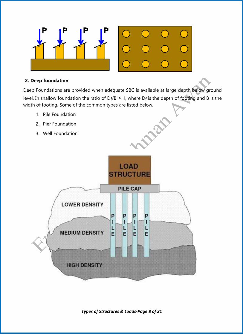
2. Deep foundation
Deep Foundations are provided when adequate SBC is available at large depth below ground
level. In shallow foundation the ratio of Df/B ≥ 1, where Df is the depth of footing and B is the
width of footing. Some of the common types are listed below.
1. Pile Foundation
2. Pier Foundation
3. Well Foundation

Types of Structures & Loads-Page 9 of 21
Once the dimensional requirements for a structure have been defined, it becomes necessary to
determine the loads the structure must support. Once the structural form has been determined,
the actual design begins with those elements that are subjected to the primary loads the
structure is intended to carry, and proceeds in sequence
to the various supporting members until the foundation
is reached. Thus, a building floor slab would be designed
first, followed by the supporting beams, columns, and
last, the foundation footings. In order to design a
structure, it is therefore necessary to first specify the
loads that act on it. The design loading for a structure is
often specified in codes. In general, the structural
engineer works with two types of codes: general building
codes and design codes. General building codes specify
the requirements of governmental bodies for minimum
design loads on structures and minimum standards for
construction. Design codes provide detailed technical
standards and are used to establish the requirements for
the actual structural design. Since a structure is generally
subjected to several types of loads, a brief discussion of these loadings will now be presented
to illustrate how one must consider their effects in practice.
Dead Loads: Dead load is defined as the load which does not change its magnitude and
position. Dead loads consist of the weights of the various structural members and the weights
of any objects that are permanently attached to the structure. Hence, for a building, the dead
loads include the weights of the columns, beams, and girders, the floor slab, roofing, walls,
windows, plumbing, electrical fixtures, and other miscellaneous attachments. Once the materials
and sizes of the various components of the structure are determined, their weights can be found
from tables that list their densities.
Loads
Load
Roof Surface
Roof slab
Beams
Column
Foundation
Soil

Types of Structures & Loads-Page 10 of 21
Minimum Densities for Design Loads from Materials
Material 𝐥𝐛/𝐟𝐭𝟑 𝐊𝐍/𝐦𝟑
Aluminum
Copper
Iron
Lead
Steel, Rolled
Limestone, Marble
Sand stone
Shale or slate
Oil
Water
Ice
Brick
Cement, Portland, set
Cement, Portland, loose
Earth, dry, packed
Concrete, plain cinder
Concrete, plain stone
Concrete, reinforced cinder
Concrete, reinforced stone
Clay, dry
Clay, damp
Masonry, lightweight solid concrete
Masonry, normal weight
Plywood
Steel, cold-drawn
Wood, Douglas Fir
Wood, Southern Pine
Wood, spruce
170
556
450
710
490
165
147
175
58
62.4
56
120
183
90
95
108
144
111
150
63
110
105
135
36
492
34
37
29
26.7
87.4
70.8
111.6
77
25.9
23.1
27.5
9.12
9.81
8.8
18.9
28.7
14
14.9
17
22.6
17.4
23.6
9.9
17.3
16.5
21.2
5.7
77.3
5.3
5.8
4.5
Frame Partitions & Walls Psf KN/m2
Exterior stud walls with brick veneer 48 2.30
Windows, glass, frame and sash 8 0.38
Wood studs 2×4 in.(51×102mm) unplastered 4 0.19
Wood studs 2×4 in.(51×102mm) plastered one side 12 0.57
Wood studs 2×4 in.(51×102mm) plastered two sides 20 0.96
Floor Fills
Cinder concrete, per inch (mm) 9 0.017
Lightweight concrete, plain, per inch (mm) 8 0.015
Stone concrete, per inch (mm) 12 0.023

Types of Structures & Loads-Page 11 of 21
Ceilings
Acoustical fiberboard 1 0.05
Plaster on tile or concrete 5 0.24
Suspended metal lath and gypsum plaster 10 0.48
Asphalt shingles 2 0.10
Fiberboard 1/2in, (13 mm) 0.75 0.04
Live Loads: Live Loads can vary both in their magnitude and location. They may be caused by
the weights of objects temporarily placed on a structure, moving vehicles, or natural forces. The
minimum live loads specified in codes are determined from studying the history of their effects
on existing structures. Usually, these loads include additional protection against excessive
deflection or sudden overload. Various types of live loads can be found from table listed below.
Sr.
No Occupancy/Use
Live Load
Kgs/m2
N/m2
Lb/ft2
1 Private apartment, schools class room 200 1900 40
2 Office 250 to 425 2400 to 4000 50 to 85
3 Fixed-seats, assembly halls, library reading
rooms 300 2900 60
4 Corridors in public buildings 400 3800 80
5 Moveable seats assembly halls 500 4800 100
6 Wholesales, light storage, warehouses 610 6000 125
7 Library Stack room 730 7200 150
8
Heavy manufacturing. Heavy storage
warehouses, sidewalks and drive ways
subjected to trucking
1200 12000 250
9 Stairs, generals 500 4800 100
10 Stairs up to two-family residences, 50%
more than specifications 300 2900 60
Snow Loads: In some parts of the country, roof loading due to snow can be quite severe, and
therefore protection against possible failure is of primary concern. Design loadings typically
depend on the building’s general shape and roof geometry, wind exposure, location, its
importance, and whether or not it is heated. Like wind, snow loads in the ASCE 7-10 Standard
are generally determined from a zone map reporting 50-year recurrence intervals of an extreme
snow depth.
Specifications for snow loads are covered in the ASCE 7-10 Standard. If a roof is flat, defined as
having a slope of less than 5%, then the pressure loading on the roof can be obtained the
following empirical formula:
𝑃𝑓 = 0.7𝐶𝑒𝐶𝑡𝐼𝑠𝑝𝑔

Types of Structures & Loads-Page 12 of 21
Where:
𝐶𝑒= an exposure factor which depends upon the terrain. For example, for a fully
exposed roof in an unobstructed area, 𝐶𝑒=0.8
Whereas if the roof is sheltered and located in the center of a large city, then 𝐶𝑒=1.2
𝐶𝑡= a thermal factor which refers to the average temperature within the building.
For unheated structures kept below freezing 𝐶𝑡 = 1.2
Whereas if the roof is supporting a normally heated structure, then 𝐶𝑡 = 1
𝐼𝑠= the importance factor as it relates to occupancy. For example, for agriculture
and storage facilities 𝐼𝑠= 0.8, and for schools and hospitals 𝐼𝑠=1.2
If 𝑃𝑔 ≤ 20𝑙𝑏/𝑓𝑡2 (0.96 KN/𝑚2) then use the largest value for 𝑃𝑓 either computed from the above
equation or from 𝑃𝑓 = 𝐼𝑠𝑝𝑔.If 𝑃𝑔 > 20𝑙𝑏/𝑓𝑡2((0.96 KN/𝑚2) then use pf =𝐼𝑠 20𝑙𝑏/𝑓𝑡2
Wind Loads: When structures block the flow of wind, the wind’s kinetic energy is converted
into potential energy of pressure, which causes a wind loading. The effect of wind on a structure
depends upon the density and velocity of the air, the angle of incidence of the wind, the shape
and stiffness of the structure, and the roughness of its surface.
Highway Bridge Loads: The primary live loads on bridge spans are those due to traffic, and
the heaviest vehicle loading encountered is that caused
by a series of trucks. Specifications for truck loadings on
highway bridges are reported in the LRFD Bridge Design
Specifications of the American Association of State and
Highway Transportation Officials (AASHTO). For two-
axle trucks, these loads are designated with an H,
followed by the weight of the truck in tons and another number which gives the year of the
specifications in which the load was reported. H-series truck weights vary from 10 to 20 tons.
However, bridges located on major highways, which carry a great deal of traffic, are often
designed for two-axle trucks plus a one-axle semitrailer
as in Fig. These are designated as HS loadings. In
general, a truck loading selected for design depends
upon the type of bridge, its location, and the type of
traffic anticipated. The size of the “standard truck” and
the distribution of its weight is also reported in the
specifications. Although trucks are assumed to be on the road, all lanes on the bridge need not
be fully loaded with a row of trucks to obtain the critical load, since such a loading would be
highly improbable.

Types of Structures & Loads-Page 13 of 21
Impact Loads: Moving vehicles may bounce or side-sway as they move over a bridge, and
therefore they impart an impact to the deck. The percentage increase of the live loads due to
impact is called the impact factor, I. This factor is generally obtained from formulas developed
from experimental evidence. For example, for highway bridges the AASHTO specifications
require that:
I= 50
𝐿+125 𝑏𝑢𝑡 𝑛𝑜𝑡 𝑙𝑎𝑟𝑔𝑒𝑟 𝑡ℎ𝑎𝑛 0.3
Where L is the length of the span in feet that is subjected to the live load.
In some cases provisions for impact loading on the structure of a building must also be taken
into account. For example, the ASCE 7-10 Standard requires the weight of elevator machinery
to be increased by 100%, and the loads on any hangers used to support floors and balconies to
be increased by 33%.
Design Codes
Building Code Requirements for Reinforced Concrete, American. Conc. Inst. (ACI)
Manual of Steel Construction, American Institute of Steel Construction (AISC)
Standard Specifications for Highway Bridges, American Association of State Highway
and Transportation Officials (AASHTO)
National Design Specification for Wood Construction, American Forest and Paper
Association (AFPA)
Manual for Railway Engineering, American Railway Engineering Association (AREA)

Types of Structures & Loads-Page 14 of 21
Example 1.1: The floor of a heavy storage warehouse building is made of
6in.-thick concrete. The floor is a slab having a length of 10 ft and width of 8
ft. Determine the total factored concentrated load.
Solution:
Dead Load = 150 𝑙𝑏/𝑓𝑡3 × {(6"
12) × (8𝑓𝑡) × (10𝑓𝑡)}
=6000lb =6 kips
Live Load=250 𝑙𝑏/𝑓𝑡2 × (8𝑓𝑡) × (10𝑓𝑡)
=20000 lb=20 ki
Factored Load =1.2(6) + 1.6(20)
= 39.2 kips
Example 1.2: The “New Jersey” barrier is commonly used during highway
construction. Determine its weight per foot of length if it is made from plain
stone concrete.
Solution:
sin 55
12=
sin 35
𝑥⇒ 𝑥 = 8.4𝑖𝑛
sin 75
𝑥=
1.6
sin 15⇒ 𝑥 = 5.97𝑖𝑛
Cross-sectional Area
= (6×24)+(7.2×12) +2(1
2×8.4×12)
+(4×5.97)+ 2(1
2×1.6×5.97)=364.63 in2=2.53ft2
Load per unit length= 2.53×144=364.32 lb/ft
Exercise

Types of Structures & Loads-Page 15 of 21
Example 1.3: The floor beam is used to support the 6-ft width of a
lightweight plain concrete slab having a thickness of 4 in. The slab serves as
a portion of the ceiling for the floor below, and
therefore its bottom is coated with plaster.
Furthermore, an 8-ft-high, 12-in.-thick
lightweight solid concrete block wall is directly
over the top flange of the beam. Determine the
dead load on the beam measured per foot of
length of the beam.
Solution:
Dead load of lightweight plain Concrete Slab
= 8𝑙𝑏
𝑓𝑡2.𝑖𝑛× 4𝑖𝑛 × 6𝑓𝑡 =192lb/ft
Dead load of Plaster Ceiling = 5𝑙𝑏
𝑓𝑡2× 6𝑓𝑡 =30lb/ft
Lightweight Concrete Block Wall = 105𝑙𝑏
𝑓𝑡3 × 8𝑓𝑡 × 1𝑓𝑡=840lb/ft
Total dead Load on Beam= 192+30+840=1062 lb/ft
Example 1.4:
The unheated storage facility as shown is
located on flat open terrain in Murree,
where the specified ground snow load is
15lb/ft2. Determine the design snow load on
the roof which has a slope of 40.
Solution:
Since the roof slope is < 50, So Ce=0.8 due to
the open area, Ct = 1.2 and Is= 0.8.Thus,
𝑃𝑓 = 0.7𝐶𝑒𝐶𝑡𝐼𝑠𝑝𝑔
=0.7(0.8)(1.2)(0.8)(15lb/ft2)= 8.06 lb/ft2
Since 𝑝𝑔=15lb/ft2<20lb/ft2, then also
𝑃𝑓 = Is𝑝𝑔=1.2(15lb/ft2) =18lb/ft2
By comparison choose 𝑃𝑓 =18lb/ft2

Types of Structures & Loads-Page 16 of 21
Example 1.5:
An unheated horse stall has a flat roof with a slop of 80mm/m. it is located
in open field where the ground snow load is 0.72 KN/m2. Determine the snow
load that is requires to design the roof of the stall.
Solution:
𝜃 = tan−1(80
1000) = 4.57° < 5°
Ce=0.8
Ct = 1.2
Is= 1.2
𝑃𝑓 = 𝐶𝑒𝐶𝑡𝐼𝑠𝑝𝑔
=0.7(0.8)(1.2)(1.2)(0.72 KN/m2)
=0.81KN/m2
Since 𝑝𝑔=0.72 KN/m2<0.96 KN/m2,
Then also 𝑃𝑓 = Is𝑝𝑔=1.2(0.72 KN/m2) = 0.576 KN/m2
By comparison choose 𝑃𝑓 =0.81 KN/m2

Types of Structures & Loads-Page 17 of 21
Example 1.6:
The slab of a library room is supported by beams AB, CD and DE as shown.
Each beam is 15ft long and are spaced 7ft on centers. The slab is made from
normal weight reinforced concrete that is 6in thick. Calculate the factored
dead load per ft of length on edge and center beams.
Solution:
The dead load on the floor is due to the weight of the concrete slab. Since 𝐿𝑦
𝐿𝑥 =
15
7 = 2.14 it is a one way slab and it delivers its load to the supporting
members by one-way action).
Factored dead load on edge beam= 1.2(150×3.5ft×0.5ft) =262.5 lb/ft
Factored dead load on center beam= 1.2(150×7ft×0.5ft) =525 lb/ft
Center Beam Edge Beam
15ft
7 ft
7 ft
A
C
E
B
D
F
15ft
7 ft
3.5
ft 3
.5 ft
15ft
7 ft
3.5
ft
525 lb/ft 262.5 lb/ft
A B C D

Types of Structures & Loads-Page 18 of 21
Example 1.7:
The floor of a classroom is to be supported by the bar joists shown in Fig.
Each joist is 15ft long and they are spaced 2.5ft on centers. The floor itself is
to be made from lightweight concrete that is
4 in. thick. Neglect the weight of the joists and
the corrugated metal deck, and determine the
load that acts along each joist.
Solution:
The dead load on the floor is due to the
weight of the concrete slab. Since Ly/Lx >2 the concrete slab is treated as a
one-way slab.
Load due to light weight concrete slab=8𝑙𝑏
𝑓𝑡2.𝑖𝑛× 4𝑖𝑛 × 2.5𝑓𝑡 =80lb/ft
The live load for a classroom is 40 lb/ft2
Live load acting on the joist=40 lb/ft2× 2.5𝑓𝑡=100 lb/ft
Therefore the uniform load along on joist=w=80+100=180 lb/ft

Types of Structures & Loads-Page 19 of 21
Example 1.8:
Consider the framing system in which a reinforced concrete slab having a
thickness of 6in is placed on the beams AB, CD, and EF and these beams are
rest on the girders AE and BF as shown. The length of the beam is 10ft and
these are placed 5ft center to center. Determine the load per ft of length on
beams and concentrated load on each column A, B, E and F.
Solution:
Since Ly/Lx ≥2 the concrete slab is treated as a one-way slab.
Density of the concrete=150 lb/ft3
Load on the beam AB and EF= 150× 2.5 ×6
12 =187.5 lb/ft
Load on the beam CD= 150× 5 ×6
12 =375 lb/ft
Load on the girder AE and BF from beam AB= (187.5×10)/2=937.5lb
Load on the girder AE and BF from beam EF= (187.5×10)/2=937.5lb
Load on the girder AE and BF from beam CD= (375×10)/2=1875lb
375 lb/ft 187.5 lb/ft
A B C D
10ft 10ft
1875
lb 1875 937.5 937.5
Types of Structures & Loads-Page 20 of 21
Load on the column=937.5+(1875/2)=1875lb
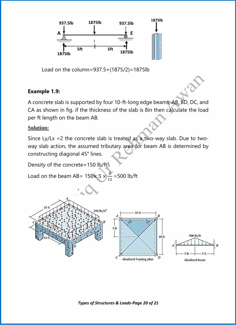
Example 1.9:
A concrete slab is supported by four 10-ft-long edge beams, AB, BD, DC, and
CA as shown in fig. if the thickness of the slab is 8in then calculate the load
per ft length on the beam AB.
Solution:
Since Ly/Lx <2 the concrete slab is treated as a two-way slab. Due to two-
way slab action, the assumed tributary area for beam AB is determined by
constructing diagonal 45° lines.
Density of the concrete=150 lb/ft3.
Load on the beam AB= 150× 5 ×8
12 =500 lb/ft
A E
937.5lb 1875lb 937.5lb
5ft 5ft 1875lb 1875lb
1875lb

Types of Structures & Loads-Page 21 of 21
Example 1.10:
A slab of length 15ft and width 10ft is supported by four edge beams, AB, BD,
DC, and CA as shown in fig. If the slab is made from reinforced concrete having
a thickness of 8in then calculate the load per ft length on the beam AB and AC.
Solution:
As Ly/Lx <2 the concrete slab is treated as a two-way slab. Density of the
concrete=150 lb/ft3
Load on the beam AB= 150× 5 ×8
12 =500 lb/ft
Load on the beam AC= 150× 5 ×8
12 =500 lb/ft
Example 1.11:
The flat roof of the steel-frame building shown in the photo is intended to
support a total load of 2KN/m2 over its surface. Determine the roof load that is
transmitted to beam BC.
Solution:
In this case Lx=4m and Ly=5m. Since
Ly/Lx=1.25<2 we have two-way slab
action. Load on surface of the slab=
2KN/m2
Load on the beam BC
= (2KN/m2× 2)+(2KN/m2× 2) =8KN/m
8KN/m