Analysis and evaluation of heat affected zones in … · copper electrodes on the die sinking...
8
Indian Journal of Engineering & Materials Sciences Vol 17, April 2010, pp. 91-98 Analysis and evaluation of heat affected zones in electric discharge machining of EN-31 die steel Rajesh Choudhary a *, H Kumar b & R K Garg c a Department of Mechanical Engineering, Malout Institute of Management & Information Technology, Malout 152 107, India b Department of Mechanical Engineering, UIET, Panjab University, Chandigarh 160 014 , India c Department of Industrial Engineering, National Institute of Technology, Jalandhar 144 011, India Received 31 October 2008; accepted 5 March 2010 In this paper investigations are conducted on the machining of EN-31 die steel with different electrode materials (copper, brass and graphite) with electrical discharge machining (EDM) process. This study presents the analysis and evaluation of heat affected zones (HAZ) of the workpiece surfaces machined using different tool electrodes by EDM. The kerosene oil of commercial grade has been used as dielectric fluid. The effect of various important EDM parameters such as pulse duration, peak current and discharge gap voltage has been investigated to yield the responses in terms of material removal rate (MRR) and surface roughness (SR). Further the detailed analysis of heat affected regions has been carried out by using scanning electron microscopy (SEM) and optical microscopy (OM). Experimental results indicate that copper as a tool electrode shows a good response towards MRR, whereas brass gives superior surface finish as compared to other tool electrodes. From the microstructural analysis study it has been observed that heat affected zone is much deeper in the specimen machined by graphite electrode as compared to other tool electrodes. Keywords: Electrical discharge machining; Surface integrity; Metal removal rate; Surface roughness; Heat affected zone The basis of electrical discharge machining (EDM) can be traced as far back as 1770, when English scientist Joseph Priestly discovered the erosive effect of electrical discharges or sparks 1 . Later, Lazarenko and Lazarenko 2 exploited the destructive properties of electrical discharges for constructive use. They developed a controlled process of machining difficult- to-machine metals by vaporizing material from the surface of metal. The Lazarenko’s EDM system, later served as the model for successive development in EDM 3 . The literature survey related to EDM reveals that surface characteristics of components machined by EDM mostly depends upon the selected electrical parameters. The importance of surface integrity of EDMed components has been recognized by the industry and it is still continues to be the major concern among the researchers. Surface integrity deals basically with two issues, i.e., surface topography and surface metallurgy. It deals with the possible alterations in the surface layers after machining. Surface integrity greatly affects the performance, life and reliability of the components. Microscopic study of EDMed components reveals the presence of three kinds of layers, e.g., recast layer, heat affected zone (HAZ) and converted layer 4 . Figure 1 shows these three kinds of layers developed on electro-discharged machined components. If molten material from the workpiece is not flushed out quickly, it will resolidify and harden due to the cooling effect of the dielectric and gets adhered to the machined surface. This thin layer of about 2.5-50 μm is formed and is called re-cast layer. It is extremely hard, brittle and porous and may contain micro cracks. Such surface layers should be removed before _______________________ *Corresponding author (E-mail: [email protected]) Fig. 1— Schematic diagram of three kinds of layers on an EDMed component 4
Transcript of Analysis and evaluation of heat affected zones in … · copper electrodes on the die sinking...

Indian Journal of Engineering & Materials Sciences
Vol 17, April 2010, pp. 91-98
Analysis and evaluation of heat affected zones in electric discharge machining of
EN-31 die steel
Rajesh Choudharya*, H Kumar
b & R K Garg
c
aDepartment of Mechanical Engineering, Malout Institute of Management & Information Technology, Malout 152 107, India bDepartment of Mechanical Engineering, UIET, Panjab University, Chandigarh 160 014 , India
cDepartment of Industrial Engineering, National Institute of Technology, Jalandhar 144 011, India
Received 31 October 2008; accepted 5 March 2010
In this paper investigations are conducted on the machining of EN-31 die steel with different electrode materials
(copper, brass and graphite) with electrical discharge machining (EDM) process. This study presents the analysis and
evaluation of heat affected zones (HAZ) of the workpiece surfaces machined using different tool electrodes by EDM. The
kerosene oil of commercial grade has been used as dielectric fluid. The effect of various important EDM parameters such as
pulse duration, peak current and discharge gap voltage has been investigated to yield the responses in terms of material
removal rate (MRR) and surface roughness (SR). Further the detailed analysis of heat affected regions has been carried out
by using scanning electron microscopy (SEM) and optical microscopy (OM). Experimental results indicate that copper as a
tool electrode shows a good response towards MRR, whereas brass gives superior surface finish as compared to other tool
electrodes. From the microstructural analysis study it has been observed that heat affected zone is much deeper in the
specimen machined by graphite electrode as compared to other tool electrodes.
Keywords: Electrical discharge machining; Surface integrity; Metal removal rate; Surface roughness; Heat affected zone
The basis of electrical discharge machining (EDM)
can be traced as far back as 1770, when English
scientist Joseph Priestly discovered the erosive effect
of electrical discharges or sparks1. Later, Lazarenko
and Lazarenko2 exploited the destructive properties of
electrical discharges for constructive use. They
developed a controlled process of machining difficult-
to-machine metals by vaporizing material from the
surface of metal. The Lazarenko’s EDM system, later
served as the model for successive development in
EDM3. The literature survey related to EDM reveals
that surface characteristics of components machined
by EDM mostly depends upon the selected electrical
parameters. The importance of surface integrity of
EDMed components has been recognized by the
industry and it is still continues to be the major
concern among the researchers. Surface integrity
deals basically with two issues, i.e., surface
topography and surface metallurgy. It deals with the
possible alterations in the surface layers after
machining. Surface integrity greatly affects the
performance, life and reliability of the components.
Microscopic study of EDMed components reveals the
presence of three kinds of layers, e.g., recast layer,
heat affected zone (HAZ) and converted layer4.
Figure 1 shows these three kinds of layers developed
on electro-discharged machined components. If
molten material from the workpiece is not flushed out
quickly, it will resolidify and harden due to the
cooling effect of the dielectric and gets adhered to the
machined surface. This thin layer of about 2.5-50 µm
is formed and is called re-cast layer. It is extremely
hard, brittle and porous and may contain micro
cracks. Such surface layers should be removed before
_______________________ *Corresponding author (E-mail: [email protected])
Fig. 1— Schematic diagram of three kinds of layers on an EDMed
component4

INDIAN J. ENG. MATER. SCI., APRIL 2010
92
using these products. Beneath the recast layer, a HAZ
is formed due to rapid heating and quenching cycles
during EDM4. This layer is approximately 25 µm
thick. The heating-cooling cycle and diffused material
during machining are the responsible reasons for the
presence of this zone. Thermal residual stresses, grain
boundary weaknesses, and grain boundary cracks are
some of the characteristics of this zone. Conversion
zone (or converted layer) is identified below the HAZ
and is characterized by a change in grain structure
from the original structure4.
There are many process variables that affect the
surface integrity such as pulse duration, peak current,
gap voltage, electrode polarity, material properties of
tool electrode, workpiece dielectric liquid, debris
concentration and even size of the electrode5. These
effects have tremendous effect on mechanical
properties of the material such as fatigue, hardness
corrosion and wear resistance6.
The texture of eroded surface has been analyzed by
Kahng and Rajurkar7. It is observed that the
application of higher discharge energy results in
deeper HAZ and subsequently deeper cracks. Spark
eroded surfaces have been examined by Barash to
study after-machining characteristics8.
Zang et al.9 developed a theoretical model to
estimate the surface roughness of the finished surface.
Experiments which have been carried out using AISI
1045 steel as workpiece material and copper as tool
electrode indicated that the roughness of finished
surface increases with an increase in discharge
voltage, discharge current and pulse duration.
Khan10
investigated the electrode wear and MRR
during EDM of aluminum and mild steel using copper
and brass electrode. During machining of mild steel, it
was observed that electrode undergone more wear
than during machining of aluminum. This is due to
the fact that the thermal conductivity of aluminum is
higher than that of mild steel which causes
comparatively more heat energy to dissipate into the
electrode during machining of mild steel.
Amorim et al.11
studied the behaviour of graphite and
copper electrodes on the die sinking electrical discharge
machining of AISI P20 tool steel. According to the study
graphite and copper presented similar trends of MRR at
positive polarity. Investigation further reveals that with
larger gap width EDM performance is more stable. It
means that higher MRR and lower electrode wear would
be reached. The best surface roughness Ra was obtained
for copper electrode under negative polarity11
.
Khanra et al.12
reported the debris formation at
different EDM conditions and concluded that EDM
debris consist of two types of particles. A combined
analysis of shape and EDS indicates spherical
particles consist of mainly WP material and nano
spherical particles generated from tool material. The
average particle size seems to increase with energy
input.
A study on fine finish die sinking micro EDM of
tungsten carbide was conducted using tungsten (W),
copper tungsten (CuW) and silver tungsten (AgW)
electrodes by Jahan et al.13
The performance of the
electrodes for the finishing micro EDM was based on
the achieved surface roughness and surface
characteristics with respect to MRR and electrode
wear rate (EWR). It was found that the surface
characteristics are dependent mostly on discharge
energy during machining. AgW electrode produces
smoother and defect free nano surface and CuW
electrodes archived the highest MRR followed by
AgW electrodes. In case of electrode wear the
W electrode has the lowest wear followed by CuW
and AgW electrodes.
In this paper, work on machining by EDM for
EN-31 grade tool and die steel has been presented.
Although some literature on EDM of low carbon
steels, carbides and die steels is available but all have
emphasized on machining parameters. Not more has
been mentioned on heat affected regions to
understand the mode of heat transfer which
alternatively affects the microstructure of machined
workpiece. The present investigation aims to establish
correlations between spark energy, electrode material
and HAZ during electrical discharge machining. An
analysis has also been performed on the comparative
performance of copper, brass and graphite electrodes.
Experimental Procedure
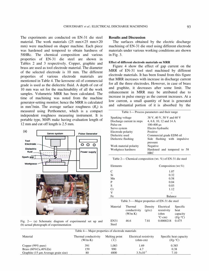
A schematic diagram of an experimental set-up for
electrical discharge machining is shown in Fig. 2. The
experiments were performed on CNC electric
discharge machine (die sinking type) of model
Sparkonix-25A having maximum capacity of 25 A
working current generator producing rectangular
pulses. The series of experiments have been
conducted to study the effect of various machining
parameters on EDM process. Various input
parameters selected to investigate the surface
characteristics and metal removal rates of tool steel
for different electrode materials. The selected
parameters for experimentation are shown in Table 1.
CHOUDHARY et al.: ELECTRICAL DISCHARGE MACHINING
93
The experiments are conducted on EN-31 die steel
material. The work materials (25 mm×25 mm×20
mm) were machined on shaper machine. Each piece
was hardened and tempered to obtain hardness of
58HRc. The chemical composition and various
properties of EN-31 die steel are shown in
Tables 2 and 3 respectively. Copper, graphite and
brass are used as tool electrode material. The diameter
of the selected electrode is 10 mm. The different
properties of various electrode materials are
mentioned in Table 4. The kerosene oil of commercial
grade is used as the dielectric fluid. A depth of cut of
10 mm was set for the machinability of all the work
samples. Volumetric MRR has been calculated. The
time of machining was noted from the machine
generator-setting monitor; hence the MRR is calculated
in mm3/min. The average surface roughness (Ra) is
measured using Perthometer, which is a compact
independent roughness measuring instrument. It is
portable type, M4Pi make having evaluation length of
12 mm and cut off length is 2.5 mm.
Results and Discussion The surfaces obtained by the electric discharge
machining of EN-31 die steel using different electrode
materials under various working conditions are shown
in Fig. 3.
Effect of different electrode materials on MRR
Figure 4 show the effect of gap current on the
MRR of EN-31 tool steel machined by different
electrode materials. It has been found from this figure
that MRR increases with increase in discharge current
for all the three electrodes. However, in case of brass
and graphite, it decreases after some limit. The
enhancement in MRR may be attributed due to
increase in pulse energy as the current increases. At a
low current, a small quantity of heat is generated
and substantial portion of it is absorbed by the
Table 4— Major properties of electrode materials
Material Thermal conductivity
(W/m-K)
Melting point
(°C)
Electrical resistivity
(ohm-cm)
Specific heat capacity
(J/g-°C)
Copper (99% pure) 391 1,083 1.69 0.385
Brass (60%Cu,40%Zn) 159 990 4.7 0.38
Graphite (15 µm Average grain size) 80 4800 3.5x10⁻³ 7.10
Fig. 2— (a) Schematic diagram of experimental set up and
(b) actual photograph of experimentation
Table 1— Process parameters and their range
Sparking voltage 38 V, 40 V, 50 V and 60 V
Discharge current in steps 4, 6.8, 10, 12 and 14 A
Pulse-on 100-400 µs
Servo system Electro hydraulic
Electrode polarity Positive
Dielectric used Commercial grade EDM oil
Dielectric flushing Side flushing with impulsive
pressure
Work material polarity Negative
Workpiece hardness Hardened and tempered to 58
HRC
Table 2— Chemical composition (wt. %) of EN-31 die steel
Elements Composition (wt.%)
C 1.07
Si 0.32
Mn 0.58
P 0.04
S 0.03
Cr 1.12
V –
Fe Balance
Table 3–—Major properties of EN-31 die steel
Material Thermal
conductivity
(W/m K)
Density
(g/cc)
Electrical
resistivity
(ohm
°C-cm)
Specific
heat
capacity
(J/g-°C)
EN31
Steel
46.6 7.81 0.0000218 0.475

INDIAN J. ENG. MATER. SCI., APRIL 2010
94
surrounding dielectric fluid and mechanical
components and therefore lesser amount of heat left
for melting and vaporizing the work material. But as
the current increases, dense spark with higher energy
is produced. Therefore, more heat is generated and
substantial quantity of heat is utilized for material
removal. MRR does not observe linearity with pulse
energy and that may be due to the possible losses of
thermal energy by conduction to surrounding material
and dielectric fluid. Except for the copper electrode,
an increase in current beyond certain limit for a given
electrode area and material has adverse effect on
MRR (Fig. 4). In all these experiments, maximum
current limit is limited to 14 A. The electrical
conductivity and thermal conductivity of EN-31
material is found to decrease with dispersed loading.
At higher levels of current, wear rate of graphite
increases and causes some machining problems which
further reduces MRR. This may be due to the arcing
produced at high current densities. Copper shows
good response in metal removal rate toward high
values of discharge current. This may be because of
the increase in thermal and electrical conductivity. As
EDM is an electro-thermal process. The electrical and
thermal conductivity and the melting point of the
electrodes and workpiece materials play an important
role in EDM performance. The high electrical
conductivity (391 W/m-K) of copper facilitates the
sparking process and increases effective pulses which
increase MRR. Thermal conductivity of graphite
(80 W/m-K) is lower as compared to brass
(159 W/m-K) and copper (391 W/m-K) which creates
substantial amount of heat in the inter electrode gap,
due to which MRR of graphite is higher upto 10 A
Fig. 4— Comparison of MRR obtained using different tool
electrodes
Fig. 5— Comparison of SR obtained using different tool
electrodes
Fig. 3— EN-31 work material after EDM at 14 A with (a) copper tool electrode, (b) brass tool electrode and (c) graphite tool electrode

CHOUDHARY et al.: ELECTRICAL DISCHARGE MACHINING
95
gap current. Afterwards the effect of arcing dominates
the removal of material from workpiece due to
insufficient spark interval. At higher discharge
current, the work particles which erode during the
EDM process did not get effective expulsion due to
the lack of turbulence. Therefore, these particles
remained in crater and hindered pace of erosion14
.
Moreover, the excessive energy provided by plasma
channel associated with characteristics, excessive
pulse on-time duration melts the material but is
unable to produce exploding pressure of the dielectric
which can remove the molten metal away from EDM
surface.
The effect of current on MRR using different
electrodes can be easily visualized from the following
summary:
(i) 50 V (gap voltage), 14 A, MRR = 26.5
mm3/min (copper electrode)
(ii) 38 V (gap voltage), 8 A, MRR = 13.9
mm3/min (brass electrode)
(iii) 40 V (gap voltage), 10 A, MRR = 18.2
mm3/min (graphite electrode)
Effect of different electrode materials on surface roughness
The surface produced by EDM process at high
current is found to be rough. During the
experimentation an average surface roughness of
EDM machined surface has been measured. As shown
in Fig. 5 the SR is found to increase with the increase
in discharge current. Minimum SR values for EN-31
steel were noticed corresponding to discharge current
of 4 A and 10 µs pulse on-time. Surface roughness
increases with increase in discharge duration15
.
At 10 µs pulse on-time, the value for SR for different
electrode materials is minimum as compared to
400 µs pulse on-time. A comparison graph as shown
in Fig. 5 shows general trend of increasing surface
roughness with current. It can be observed from this
figure that graphite tool electrode promoted higher
roughness than copper and brass electrode for all the
discharge current and discharge durations. The higher
SR obtained with graphite is due to the higher MRR
reached for that material. This means that larger and
deeper craters were made in the workpiece surface
using graphite electrode. The best value of SR has
been attained by using brass electrode, which is
recommended for high surface finish of workpiece
material after machining. However, the MRR of the
brass electrode for all the discharge current and
duration is minimum, which shows the lesser removal
of material from workpiece with reduced size of
craters. It is found that SR values of graphite are more
as compared to copper, followed by brass. It is further
observed that the surface of specimen machined by
EDM is affected by alloying element of tool electrode
material. So it was considered that the alloying effect
could be used to enhance surface quality such as
reducing residual stresses by a suitable source of
alloying element16
.
It has been further concluded from the
experimental results that if the graphite electrode
assigned as cathode and operated under appropriate
pulse duration, the removal rate of workpiece have a
superior approach in reality.
Analysis of heat affected zones of machined surfaces
The alloy EN-31 die steel consists of different
alloying elements. In order to have higher tool life, it is
essential to avoid crack formation if any even, while
workpiece is in service. It is therefore essential to
analyze the surface beneath the machined area17
. Figure
3 shows the surfaces of specimens machined with
different electrodes materials. The SR is observed to be
uniform in the cavity machined by copper electrode
along with minimum wear at corner edge (Fig.3a).
Figure 3b shows cavity machined by brass electrode
with minimum surface roughness as compared to
copper and graphite electrode. This may be attributed
due to the transfer of copper and zinc on the surface of
workpiece during machining due to intense heat.
During machining it was observed that, at higher
voltage high, corner wear of the graphite electrode and
erosion of work material take place. Thus the sparks
are concentrated in the middle of machined area,
thereby causing short circuiting and arcing at the
middle of this area. Due to the arcing spattering of the
electrode material take place over the entire cavity.
Further, from the Fig. 3c it could be observed that
accumulation of resolidified layer of work material and
graphite take place on the workpiece surfaces. In the
present research work, the structure features of such
areas have been analyzed critically. In order to analyze
such surfaces, the pieces are cut from the center in
transverse direction. The samples are mechanically
polished. The polishing is done first on belt grinder
followed by emery and silver cloth. In order to make
glossy and mirror finish surfaces, diamond paste is
used. After achieving the mirror finish the surface was
etched with nital itchant. The surface topography of
EDM was investigated by JEOL 5600 JSM scanning
electron microscope. The SEM photographs taken from
INDIAN J. ENG. MATER. SCI., APRIL 2010
96
different surfaces machined by various electrode
materials are shown in Figs 6-8. The photographs
reveal that structures with martensite and spherical to
ellipsoidal carbides are present and their concentration
depends upon the available amount of heat in the inter
electrode gap with different electrode materials. Figure
6 represents the structural features of such transverse
section of the surfaces where brass electrode is used.
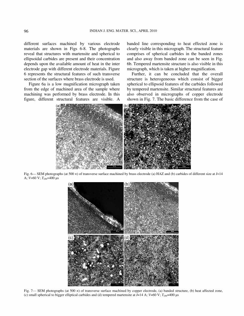
Figure 6a is a low magnification micrograph taken
from the edge of machined area of the sample where
machining was performed by brass electrode. In this
figure, different structural features are visible. A
banded line corresponding to heat effected zone is
clearly visible in this micrograph. The structural feature
comprises of spherical carbides in the banded zones
and also away from banded zone can be seen in Fig.
6b. Tempered martensite structure is also visible in this
micrograph, which is taken at higher magnification.
Further, it can be concluded that the overall
structure is heterogeneous which consist of bigger
spherical to ellipsoid features of the carbides followed
by tempered martensite. Similar structural features are
also observed in micrographs of copper electrode
shown in Fig. 7. The basic difference from the case of
Fig. 6— SEM photographs (at 500 ×) of transverse surface machined by brass electrode (a) HAZ and (b) carbides of different size at I=14
A; V=60 V; TON=400 µs
Fig. 7— SEM photographs (at 500 ×) of transverse surface machined by copper electrode, (a) banded structure, (b) heat affected zone,
(c) small spherical to bigger elliptical carbides and (d) tempered martensite at I=14 A; V=60 V; TON=400 µs

CHOUDHARY et al.: ELECTRICAL DISCHARGE MACHINING
97
brass electrode is that the amount of tempered
martensite is more and pronounced one. The size of
the carbides varies from 1 µm to 3 µm, which are
developed beneath the heat affected zone as shown in
Fig. 7c. Moreover, structural variation in tempered
martensite can also be seen in Fig. 7d. This type of
variation is only possible, if heat transfer is not
occurring uniformly.
The structural features observed for the graphite
electrode, are shown in Fig. 8. In case of surface
machined by graphite electrode, the formation of
spherical shape carbides is much deeper. Though the
sizes of these carbides are very small (Figs 8a and 8b)
in the area around the machined surface but it
acquires the bigger shape from the area away from the
machined surface (Fig. 8c). The formation of
tempered martensite along with carbides can also be
evident in Fig. 8d. In case of graphite electrode the
heat affected zone is much deeper as compare to other
two electrodes.
The overall examination of structural features
indicates that the surface is modified differently
because of the application of different electrodes
materials on the workpiece and effect of various
machining parameters. In cases of graphite electrode,
thick white layer on the surface is not observed
because of the volcanic eruption, which has taken
place during the course of machining of the surfaces.
However, area which is being influenced by the heat
is deeper and uniform as compare to other electrodes.
The carbides which are in the form of needles are
being converted to spherical shapes because of the
thermal influence and surface tension. This spherical
shape is obtained because of higher heat content.
Moreover, rapid quenching may lead to formation of
martensite structure in the material. Since the system
is dynamic where a continuous flow of energy
followed by quenching phenomenon occurs, so the
structure obtained is not converted into martensite
structure. Intervariate structure is normally obtained
after the tempering of steel, which is called tempered
martensite and is also visible in the specimen. Since
workpiece always remain at higher temperature, so
this phenomenon is quite obvious to occur. The
overall analysis of structure features reveals that heat
affected zone may vary depending upon the available
amount of heat, its conduction through the workpiece
and quenching mode existing within the system.
Fig. 8— SEM Photographs (at 500 ×) of transverse surface machined by graphite electrode (a) HAZ, (b) banded features, (c) segregation
of massive carbides and (d) fine carbides along with tempered martensite at I=14 A; V=60 V; TON=400 µs

INDIAN J. ENG. MATER. SCI., APRIL 2010
98
Conclusions After analyzing the results of the experiment
performed on EN-31 die steel with different electrode
materials, following conclusions are arrived at:
(i) For the EN-31 work material, copper
electrodes offer high MRR as compared to
the machining performed by graphite and
brass electrodes.
(ii) Among the three tested electrode materials,
brass electrodes produce comparatively high
surface finish for the tested work material at
high values of discharge current, while
graphite shows the poor surface finish.
(iii) It has been observed that with the increase of
the discharge energy, the amount of debris
particles in the gap becomes too large which
form electrically conductive path between
the tool electrode and the workpiece, causing
unwanted discharges that damages both the
electrode surfaces.
(iv) All three workpieces machined by different
electrodes materials shows different pattern
of heat affected zones.
(v) Heat affected zones for all the cases depends
upon available amount of heat, its conduction
and cooling action during the EDM process.
(vi) In case of graphite electrode heat affected
zone is much deeper as compared to copper
and brass electrode.
References 1 Webzell S, Machinery, 41 (2001) 159.
2 Anonymous, History and development in: The techniques
and practice of spark erosion machining (Sparcatron
Limited, Gloueser, UK), 1965, 6.
3 Livshits A L, Introduction in Electro-erosion machining of
metals (Department of Sci. & Ind. Res., Butterworth & Co.,
London), 1960.
4 Jain V K, Advanced machining processes (Allied Publishers
Pvt. Ltd.,) 2008, 154-155.
5 Lee H T, Hsu F C & Tai T Y, Mater Sci Eng, A36 (2004)
346–356.
6 Huang C A, Hsu F Y & Yao S J, Mater Sci Eng, A371
(2004) 119–126.
7 Kahng C H & Rajurkar K P, Ann CIRP, 25 (1977) 77-82.
8 Barash M, Microtecnic, (1959) 51-54.
9 Zang Q H, Zang J H, Ren S F & Niu X Ai, Int J Manuf
Technol & Mgt, 7 (2005) 381-390.
10 Khan A A, Int J Adv Manuf Technol, 39 (2008) 482-487.
11 Amorim F L & Weingaertner W L, J Brazil Soc Mech Sci &
Eng, 29 (2007) 366-371.
12 Khanra A K, Pathak L C & Godkhindi M M, J Mater Sci, 42
(2007) 872-877.
13 Jahan M P, Wong Y S & Rahman M, J Mater Process
Technol, 209 (2009) 3956-3967.
14 Pandey P C & Jilani S T, Wear, 116 (1987) 77-88.
15 Choudhary R, Investigating the proper tool electrode for EN-
31 Tool steel in electrical discharge machining process, M.
Tech. Thesis, National Institute of Technology, Jallandhar,
2007.
16 Ekmekci B & Erden A, Remarks on Surface Integrity of
Electric Discharge Machined Surfaces, presented at 11th Int
Conf Machine Design and Production, Turkey, 2004.
17 Payal H S & Sethi B L, J Sci & Ind Res, 62 (2003) 678-682.