
ANALYSIS AND DESIGN OF BASE-ISOLATED SUSPENSION BRIDGE ...eprints.usm.my/34423/1/HBP3.pdf ·...
12
ANALYSIS AND DESIGN OF BASE-ISOLATED SUSPENSION BRIDGE UNDER SEISMIC LOADS Kyaw Lin Htat Department of Civil Engineering, Mandalay Technological University, Myanmar Email: [email protected] ABSTRACT Suspension bridges have been firmly established as the most efficient and cost effective structural form in the 500-ft to 1500-ft span range. Today, the suspension bridge is most suitable type for very long-span bridge and actually represents 20 or more of all the longest span bridges in the world. Behavior of suspension bridge is great importance as the influence of moving loads, seismic and wind forces on these structures. Seismic isolation introduces to avoid resonance with the typical predominant frequencies of earthquakes, in order to reduce the shear forces, deflections, and floor accelerations of a building, and, consequently, prevent damage of its structural and non-structural elements. In this study damper is used as isolation and energy dissipation devices for bridge subjected to earthquake loads. The simplified model is three-span continuous and main span has 260-ft and each side span has 120-ft with a steel bridge deck. Main cables are parallel-wire strands and pylons are Portal type. The bridge is designed for equivalent traffic loads of HS 20-44 trucks specified by American Association of State Highway and Transportation Officials (AASHTO). A realistic analytical suspension bridge model is developed by using STAAD.Pro finite element program. The response spectrum analysis method is used from UBC 1997 code. This paper discusses the effect of base-isolator on design of suspension bridge. Then, compared the analysis results in different between normal support condition and spring support condition. From the comparison results, the axial force in main cable is reduced by 22.6 %. Axial forces in girder are reduced about 40 % in all members of girder under spring support condition. Keywords: response spectrum analysis, seismic isolation, suspension bridge 1. INTRODUCTION Bridge building can be said the evolution of civil engineering. Transportation plays a vital role in the development of a country. Developing the nation’s transportation is to provide not only to upgrade the living standard but also to allow better circulation of goods and people. The construction of bridges and roads is the major factor that brings about socio-economic life of the people for ensuring smooth transportation, development of trade and economy. This study deals with design and construction of a suspension bridge. This type of bridge is more suitable for very long span bridges and its advantage is to prevent forming sandbanks in upstream side of the river. The origins of the suspension bridge went back a long way in history. Today’s modern suspension bridge structures are mostly based on primitive suspension bridge, or simple crossing devices. Suspension bridges, when well designed and proportioned, are clearly the most aesthetically pleasing of all bridges. Suspension bridges were constructed with iron chain cables over 2000 years ago in China and India. The modern suspension bridge originated in the 18 th century when the development of the bridge structure and the production of iron started on a full-scale 2nd INTERNATIONAL CONFERENCE ON BUILT ENVIRONMENT IN DEVELOPING COUNTRIES (ICBEDC 2008) 406
Transcript of ANALYSIS AND DESIGN OF BASE-ISOLATED SUSPENSION BRIDGE ...eprints.usm.my/34423/1/HBP3.pdf ·...

ANALYSIS AND DESIGN OF BASE-ISOLATED SUSPENSION BRIDGE UNDER SEISMIC LOADS
Kyaw Lin Htat
Department of Civil Engineering, Mandalay Technological University, Myanmar Email: [email protected]
ABSTRACT
Suspension bridges have been firmly established as the most efficient and cost effective structural form in the 500-ft to 1500-ft span range. Today, the suspension bridge is most suitable type for very long-span bridge and actually represents 20 or more of all the longest span bridges in the world. Behavior of suspension bridge is great importance as the influence of moving loads, seismic and wind forces on these structures. Seismic isolation introduces to avoid resonance with the typical predominant frequencies of earthquakes, in order to reduce the shear forces, deflections, and floor accelerations of a building, and, consequently, prevent damage of its structural and non-structural elements. In this study damper is used as isolation and energy dissipation devices for bridge subjected to earthquake loads. The simplified model is three-span continuous and main span has 260-ft and each side span has 120-ft with a steel bridge deck. Main cables are parallel-wire strands and pylons are Portal type. The bridge is designed for equivalent traffic loads of HS 20-44 trucks specified by American Association of State Highway and Transportation Officials (AASHTO). A realistic analytical suspension bridge model is developed by using STAAD.Pro finite element program. The response spectrum analysis method is used from UBC 1997 code. This paper discusses the effect of base-isolator on design of suspension bridge. Then, compared the analysis results in different between normal support condition and spring support condition. From the comparison results, the axial force in main cable is reduced by 22.6 %. Axial forces in girder are reduced about 40 % in all members of girder under spring support condition.
Keywords: response spectrum analysis, seismic isolation, suspension bridge
1. INTRODUCTION
Bridge building can be said the evolution of civil engineering. Transportation
plays a vital role in the development of a country. Developing the nation’s
transportation is to provide not only to upgrade the living standard but also to allow
better circulation of goods and people. The construction of bridges and roads is the
major factor that brings about socio-economic life of the people for ensuring smooth
transportation, development of trade and economy. This study deals with design and
construction of a suspension bridge. This type of bridge is more suitable for very long
span bridges and its advantage is to prevent forming sandbanks in upstream side of
the river.
The origins of the suspension bridge went back a long way in history. Today’s
modern suspension bridge structures are mostly based on primitive suspension
bridge, or simple crossing devices. Suspension bridges, when well designed and
proportioned, are clearly the most aesthetically pleasing of all bridges. Suspension
bridges were constructed with iron chain cables over 2000 years ago in China and
India. The modern suspension bridge originated in the 18th century when the
development of the bridge structure and the production of iron started on a full-scale
2nd INTERNATIONAL CONFERENCE ON BUILT ENVIRONMENT IN DEVELOPING COUNTRIES (ICBEDC 2008)
406

basis. The distinguishing feature of the bridge was the adopting of a truss stiffening
girder which give rigidity to the bridge to distribute the load through the hanger ropes
and truss preventing excessive deformation of the cable. Suspension bridges are the
most suitable ones for large spans in the range of 500 m to 600 m. The bridge
consists of main cables, suspenders, stiffening girders and the towers. A high
strength steel cable suspended from the tops of two towers carry very high tension.
Suspenders are subjected to tension force and the stiffening girder which helps in
maintaining the shape of the bridge is subjected to bending and shear.
Today, the suspension bridge is most suitable type for very long-span bridge
and actually represents 20 % or more of all the longest span bridges in the world.
Earthquakes constitute a substantial form of excitation of structures in terms
of their large potential to cause structural damage. Therefore, the seismic resistance
of structures is carefully studied during the design phase. Seismic isolation systems
are very useful in reducing the earth quake response of structures and are being
installed in many structures. The base isolation devices (isolators) are installed
between the structures and supporting to support structure and to minimize the
damage due to earthquake loads.
2. OBJECTIVES
The main purposes of this study are described as follows:
(1) To analyze and design a three-span suspension bridge not only static
analysis for gravity and wind loading but also dynamic analysis for seismic
loading.
(2) To analyze and design helical spring supports to reduce forces in main
structural members due to seismic loads.
(3) To compare analysis results of the bridge with normal support condition
and spring support condition.
3. SCOPE OF STUDY
The proposed bridge is 500 ft three span suspension bridge with 5 ft high warren
type steel truss stiffening girder. This proposed bridge providing two lanes for
highway traffic on its reinforced concrete decking. The bridge is designed for
equivalent traffic loads of HS 20-44 trucks and loads specified by American
Association of State Highway and Transportation Officials (AASHTO). Wind load is
considered as open structure type and used ASCE code. Response spectrum
analysis is used to analysis the bridge for seismic loading. Helical spring systems are
2nd INTERNATIONAL CONFERENCE ON BUILT ENVIRONMENT IN DEVELOPING COUNTRIES (ICBEDC 2008)
407

used as bearing system in order to better protection for the case study and compared
results with normally supported bridge. Analysis and design of the bridge was carried
out by using STAAD-Pro engineering software. Then, it is compared the analysis
results in difference between normal support condition and spring support condition.
4. ANALYSIS METHODS FOR SUSPENSION BRIDGE
In the analysis producer, linear static analysis and response spectrum analysis
for the protected structures can be selected.
4.1 Static Analysis Method
Linear static analysis is permitted to be used for the design of a seismically
isolated structure, provided that:
(1) The structure is located at a site with S1 less than or equal to 0.6 g.
(2) The structure is located on a Class A, B, C, or D site.
(3) The effective period of the isolated structure, TM, is less than or equal to
3.0 sec.
(4) The effective period of the isolated structure, TD, is grater than three times
the elastic, fixed base period of the structure above the isolation system.
4.2 Response Spectrum Analysis
Response-spectrum analysis shall be performed using a modal damping value
for the fundamental mode in the direction of interest not greater than the effective
damping of the isolation system or 30 percent of critical, whichever is less. Modal
damping values for higher modes shall be selected consistent with those
appropriate for response spectrum analysis of the structure above the isolation
system with a fixed base. Response-spectrum analysis used to determine the total
design displacement and the total maximum displacement shall include
simultaneous excitation of the model by 100 percent of the most critical direction of
ground motion, and 30 percent of the ground motion on the orthogonal axis.
5. BASE ISOLATION Base isolation is an important concept in earthquake engineering. Initially, base
isolation was a very suspect process for design of earthquake resistant structures,
and engineers were wary of its applications; however, it has since become a widely
accepted approach. The goal of base isolation is to reduce the energy that is
transferred from the ground motion to the structure by buffering it with a bearing layer
2nd INTERNATIONAL CONFERENCE ON BUILT ENVIRONMENT IN DEVELOPING COUNTRIES (ICBEDC 2008)
408
at the foundation which has relatively low stiffness. The bearing level has a longer
period than the superstructure, which reduces the force and displacement demands
on the superstructure, allowing it to remain elastic and generally undamaged.
One of the important properties of a base-isolation system is that although it
is designed to be significantly more flexible than the elements of the superstructure,
it must still be stiff enough to resist typical wind loadings and similar low-amplitude
horizontal forces. Therefore, the bearings may have a relatively high initial stiffness
but will quickly reach yield, at which point the bearings have a greatly reduced
stiffness, extending the natural period of the structure.
6. DESIGN PROCEDURE FOR HELICAL SPRING ISOLATION
The design procedures of helical spring are as follows:
1. Specifying the soil condition for the isolated structure.
2. Selecting the effective damping ratio ξeff for the bearing, and the target
design period T for the isolated structure.
3. Using code formulas, or static or dynamic analysis, to determine the
effective horizontal stiffness Keff and maximum horizontal (design)
displacement D of the bearing.
4. Selecting the material properties, including Young’s modulus E and shear
modulus G, from the manufacturer’s test report.
5. Selecting the wire diameter (d), number of active coils (Na), free length
(Lo)compressed length of helical ( hs), deflection (δ) and mean coil
diameter(Dm) depending on axial load on each bearing and these
relationship.
6. Calculating the deflection (δ) for each helical spring using following
equation
4
38
dG
NDP am=δ
7. Calculating the vertical stiffness of helical spring using
a
3
4
vND8
GdK =
8. Calculating for horizontal stiffness of helical spring using
H
V
K
K= 1.44 1C ( + 265.0
D
h204.0
2
2
s )
9. Determination of total vertical stiffness for helical spring is taken from
KV( total) = K1+ K2+ K3+........
2nd INTERNATIONAL CONFERENCE ON BUILT ENVIRONMENT IN DEVELOPING COUNTRIES (ICBEDC 2008)
409
10. Calculating the required number of helical spring under each bearing
Number of helical Load on each bearing
spring under each bearing KV x δ
11. Determination of total horizontal stiffness under each bearing
KH( total) = KH x Total number of helical spring each bearing
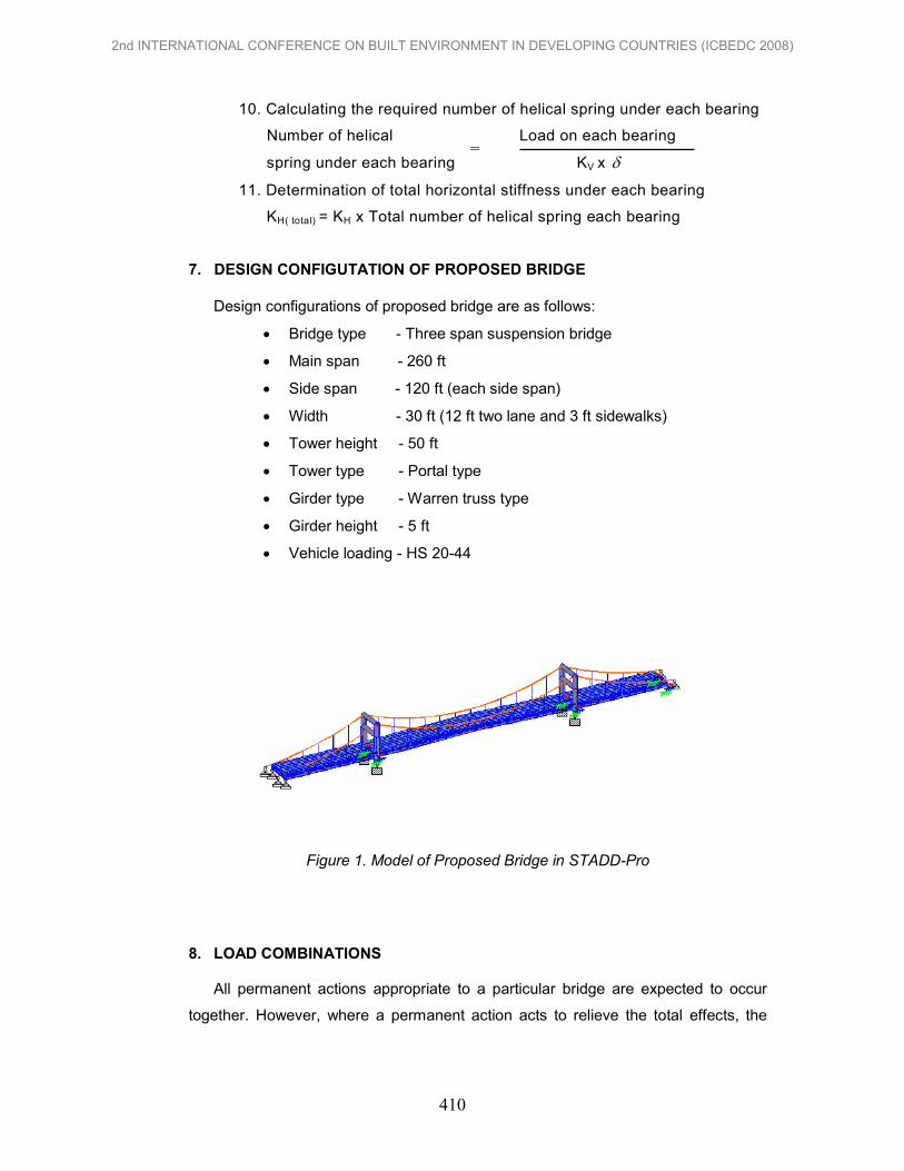
7. DESIGN CONFIGUTATION OF PROPOSED BRIDGE
Design configurations of proposed bridge are as follows:
• Bridge type - Three span suspension bridge
• Main span - 260 ft
• Side span - 120 ft (each side span)
• Width - 30 ft (12 ft two lane and 3 ft sidewalks)
• Tower height - 50 ft
• Tower type - Portal type
• Girder type - Warren truss type
• Girder height - 5 ft
• Vehicle loading - HS 20-44
Figure 1. Model of Proposed Bridge in STADD-Pro
8. LOAD COMBINATIONS
All permanent actions appropriate to a particular bridge are expected to occur
together. However, where a permanent action acts to relieve the total effects, the
=
2nd INTERNATIONAL CONFERENCE ON BUILT ENVIRONMENT IN DEVELOPING COUNTRIES (ICBEDC 2008)
410

load combination will be considered with this action removed, if such removal can
logically occur.
Load combinations to be used are as follows:
Table 1.Loading Combination for Bridge
Group Loading Combinations
I [D + 1.67 ( L + I ) ]
II [D + W ]
III [D + L + I + 0.3W]
IV [D + L + I + T ]
V [D + W + T ]
VI [D + L + I + 0.3W + T ]
VII [D + EQ ]
Where;
D = dead load
L = live load
I = live load impact
W = wind load on structure
T = temperature force
EQ = earthquake force
9. COMPARISON RESULTS BETWEEN NORMAL AND SPRING SUPPORTED
CONDITION
This section presents the different results between the original and the base
isolated suspension bridge. Firstly, maximum displacements of the bridge under
normally supported and spring supported conditions are compared. Then,
displacements of tower are compared. Displacements and axial forces of main cable,
hanger, top chord, bottom chord, vertical member and diagonal member are
compared consequently.
9.1 Displacement Comparisons
In this section, comparison results of maximum displacements under normally
supported and spring supported bridge are shown Figure 2 and figure 3.
2nd INTERNATIONAL CONFERENCE ON BUILT ENVIRONMENT IN DEVELOPING COUNTRIES (ICBEDC 2008)
411

0.3
0.35
0.4
Member
Displacement, in .
Normally Support
Spring Support
Figure 2. Maximum Displacement in Longitudinal Direction
Longitudinal maximum displacements of the bridge are occurred 0.344 inch in
normally supported bridge and 0.354 inch in spring supported bridge under
longitudinal seismic loading.
-0.5
1.5
3.5
5.5
7.5
Member
Displacement, in .
Normally Support
Spring Support
Figure 3. Maximum Displacement in Vertical Direction
Vertical displacement of the proposed bridge occurred at 5.48 inches in
normally supported bridge and 7.42 inches in spring supported bridge due to self plus
transverse seismic loading.
9.2 Tower Displacement In this section, tower displacements in longitudinal and transverse directions
are shown. These displacements are due to seismic loadings and the shapes are
also the deformation shape of the tower.
2nd INTERNATIONAL CONFERENCE ON BUILT ENVIRONMENT IN DEVELOPING COUNTRIES (ICBEDC 2008)
412

1
2
3
4
0 1 2
Displacement, in .
Tower Node Point
Tower Displacement
Figure 4. Tower Displacement in Longitudinal Direction due to EQX
Tower top displacement in longitudinal direction is 1.819 inches under
longitudinal seismic loading.
1
2
3
4
0 0.2 0.4
Displacement, in
Tower N
ode Point
Tower Displacement
Figure 5. Tower Displacement in Transverse Direction due to EQZ
Tower top displacement in transverse direction is 0.362 inch under transverse
seismic loading.
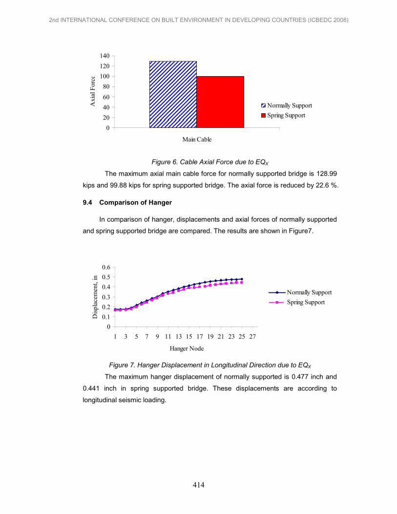
9.3 Comparison of Main Cable Axial Force
The maximum axial force of main cable comparison between normally and
spring supported bridge are as shown in Figure 6. The controlled load for maximum
axial main cable is transverse seismic loading.
2nd INTERNATIONAL CONFERENCE ON BUILT ENVIRONMENT IN DEVELOPING COUNTRIES (ICBEDC 2008)
413
0
20
40
60
80
100
120
140
Main Cable
Axial Force
Normally Support
Spring Support
Figure 6. Cable Axial Force due to EQX
The maximum axial main cable force for normally supported bridge is 128.99
kips and 99.88 kips for spring supported bridge. The axial force is reduced by 22.6 %.
9.4 Comparison of Hanger
In comparison of hanger, displacements and axial forces of normally supported
and spring supported bridge are compared. The results are shown in Figure7.
0
0.1
0.2
0.3
0.4
0.5
0.6
1 3 5 7 9 11 13 15 17 19 21 23 25 27
Hanger Node
Displacement, in .
Normally Support
Spring Support
Figure 7. Hanger Displacement in Longitudinal Direction due to EQX
The maximum hanger displacement of normally supported is 0.477 inch and
0.441 inch in spring supported bridge. These displacements are according to
longitudinal seismic loading.
2nd INTERNATIONAL CONFERENCE ON BUILT ENVIRONMENT IN DEVELOPING COUNTRIES (ICBEDC 2008)
414

0
1
2
3
4
5
1 3 5 7 9 11 13 15 17 19 21 23 25 27
Hanger Node
Displacement, in .
Normally Support
Spring Support
Figure 8. Hanger Displacement in Transverse Direction due to EQZ
The maximum hanger displacement of normally supported is 0.757 inch and
4.098 inches in spring supported bridge. These displacements are according to
transverse seismic loading.
0
2
4
6
8
10
12
0 2 4 6 8 10
Hanger
Axial Force, K
ip .
Normally Support
Spring Support
Figure 9. Hanger Axial Force due to EQX
The maximum hanger axial force is 10.8 kips in normally supported and 7.7
kip in spring supported bridge. It reduces 28.7 %.
9.5 Comparison of Girder
In this section, displacements and axial forces comparison of top chord, bottom
chord, vertical member and inclined member are compared.
a. Top Chord
Displacements and axial forces of top chords in normally and spring
supported bridge comparisons are shown in Figure10 and 11.
2nd INTERNATIONAL CONFERENCE ON BUILT ENVIRONMENT IN DEVELOPING COUNTRIES (ICBEDC 2008)
415

0
0.1
0.2
0.3
0 1 2 3 4 5 6 7 8 9 10
Top Chord
Displacement, in
Normally Support
Spring Support
Figure 10. Top Chord Displacement in Longitudinal Direction due to EQZ
Maximum top chord displacement in longitudinal of normally support is 0.036
inch and spring support is 0.278 inch due to transverse seismic loading.
0
0.5
1
1.5
0 1 2 3 4 5 6 7 8 9 10
Top Chord
Displacement, in .
Normally Support
Spring Support
Figure 11. Top Chord Displacement in Transverse Direction due to EQZ
Maximum top chord displacement in transverse direction of normally
supported bridge is 0.088 inch and spring support is 1.359 inches due to transverse
seismic loading.
b. Bottom Chord
Displacements and axial forces of bottom chords in normally and spring
supported bridge comparisons are shown in Figure 12.
2nd INTERNATIONAL CONFERENCE ON BUILT ENVIRONMENT IN DEVELOPING COUNTRIES (ICBEDC 2008)
416

0
0.1
0.2
0.3
0 1 2 3 4 5 6 7 8 9 10
Bottom Chord
Displacement, in .
Normally Support
Spring Support
Figure 12. Bottom Chord Displacement in Longitudinal Direction due to EQZ
Maximum Longitudinal bottom chord displacement of normally supported
bridge is 0.245 inch and spring supported bridge is 0.279 inch due to transverse
seismic loading.
10. CONCLUSIONS
In this study, analyzed and designed of the suspension bridge and studied the
influence of the helical spring isolator on the response of building. The following
conclusions were drawn out from analysis results and comparison of normally
supported bridge to spring supported bridge.
(1) Tower top displacement in longitudinal direction is 1.819 inches under
longitudinal seismic loading and in transverse direction is 0.362 inch under
transverse seismic loading.
(2) The maximum axial main cable force for normally supported bridge is
128.99 kips and 99.88 kips for spring supported bridge. The axial force is
reduced by 22.6 %.
(3) The maximum hanger axial force is 10.8 kips in normally supported and
7.7 kip in spring supported bridge. It reduces 28.7 %.
(4) Axial forces in girder are reduced about 40 % in all members of girder
under spring support condition.
REFERENCES
Merville K.Forrester, (2001) Stiffness Model of a Die Spring, Virginia Polytechnic Institute and State University, Blacksburg, Virginia,. Chen, W. F, Duan. L, (2000) Bridge Engineering Handbook. CRC Press. Niels J Gimsing, (2000) Cable Supported bridges, John Wiley & Sons. Farzad Naeim James M. Kelly, (1999) Design of Seismic Isolated Structures,John Wiley & Sons. Podony, (1997) Design of Modern Highway Bridges, American Marketing Services. Demetrios E. Tonias, (1995) P.E, Bridge Engineering, Mc Graw-Hill, Inc.
2nd INTERNATIONAL CONFERENCE ON BUILT ENVIRONMENT IN DEVELOPING COUNTRIES (ICBEDC 2008)
417