ANALOGUE INSULATION/CONTINUITY TESTER MODEL 3131A
24
MODEL 3131A ANALOGUE INSULATION /CONTINUITY TESTER INSTRUCTION MANUAL KYORITSU ELECTRICAL INSTRUMENTS WORKS,LTD., TOKYO JAPAN
Transcript of ANALOGUE INSULATION/CONTINUITY TESTER MODEL 3131A

MODEL 3131AANALOGUE INSULATION/CONTINUITY TESTER
INSTRUCTION MANUAL
KYORITSU ELECTRICAL INSTRUMENTS WORKS,LTD., TOKYO JAPAN
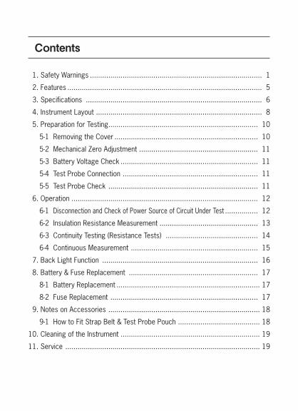
Contents
1. Safety Warnings .................................................................................... 1
2. Features ............................................................................................... 5
3. Specifications ...................................................................................... 6
4. Instrument Layout ................................................................................. 8
5. Preparation for Testing ......................................................................... 10
5-1 Removing the Cover ...................................................................... 10
5-2 Mechanical Zero Adjustment .......................................................... 11
5-3 Battery Voltage Check ................................................................... 11
5-4 Test Probe Connection .................................................................. 11
5-5 Test Probe Check ......................................................................... 11
6. Operation ........................................................................................... 12
6-1 Disconnection and Check of Power Source of Circuit Under Test ................ 12
6-2 Insulation Resistance Measurement ................................................ 13
6-3 Continuity Testing (Resistance Tests) ............................................. 14
6-4 Continuous Measurement .............................................................. 15
7. Back Light Function ............................................................................ 16
8. Battery & Fuse Replacement ............................................................... 17
8-1 Battery Replacement ...................................................................... 17
8-2 Fuse Replacement ........................................................................ 17
9. Notes on Accessories .......................................................................... 18
9-1 How to Fit Strap Belt & Test Probe Pouch ........................................ 18
10. Cleaning of the Instrument .................................................................... 19
11. Service ............................................................................................... 19

— 1 —
This instrument has been designed, manufactured and tested according to IEC 61010: Safety requirements for Electronic measuring apparatus, and delivered in the best condition after passed the inspection. This instruction manual contains warnings and safety rules which must be observed by the user to ensure safe operation of the instrument and retain it in safe condition. Therefore, read through these operating instructions before using the instrument.
# WARNING● Read through and understand the instructions contained in this manual
before using the instrument.● Keep the manual at hand to enable quick reference whenever necessary.● The instrument is to be used only in its intended applications. ● Understand and follow all the safety instructions contained in the manual.It is essential that the above instructions are adhered to. Failure to follow the above instructions may cause injury, instrument damage and/or damage to equipment under test. Kyoritsu is by no means liable for any damage resulting from the instrument in contradiction to these cautionary notes.
○ The symbol # indicated on the instrument, means that the user must refer to the related parts in the manual for safe operation of the instrument. It is essential to read the instructions wherever the symbol appears in the manual.
# DANGER :�is reserved for conditions and actions that are likely to cause serious or fatal injury.
# WARNING :�is reserved for conditions and actions that can cause serious or fatal injury.
# CAUTION :�is reserved for conditions and actions that can cause injury or instrument damage.
1. SAFETY WARNINGS

— 2 —
Please refer to following explanation of the symbols used on the instrument and in this manual.
# User must refer to the explanations in the instruction manual.
Caution, risk of electric shock.
Instrument with double or reinforced.
Protection against wrong connection is up to 440V.
EARTH GROUND
This instrument satisfies the marking requirement defined in the WEEE Directive 2002/96/EC. This symbol indicates separate collection for electrical and electronic equipment.
# DANGER● Confirm a proper operation of the instrument with a well-known power supply.● Do not use this instrument on energized (LIVE) circuits.● Do not attempt to make measurement in the presence of flammable gasses. Otherwise, the use of the instrument may cause sparking, which can lead
to an explosion.● Do not make measurement when thunder is rumbling. If the instrument is
in use, stop the measurement immediately and remove the instrument from the measured object.
● Never attempt to use the instrument if its surface or your hand is wet.● Never open the battery compartment cover and the instrument case when
making a measurement.● Do not exceed the maximum allowable input of measuring ranges.● The instrument is to be used, only in its intended applications or conditions. Otherwise, safety functions equipped with the instrument doesn't work,
and instrument damage or serious personal injury may be caused.● Always Keep your fingers and hands behind the protective fingerguard on
test probe to avoid the possible shock hazard.

— 3 —
# WARNING● Never attempt to make any measurement, if the instrument has any
structural abnormality such as cracked case or exposed metal parts.● Do not turn the range selector switch while the test probe are connected
to the circuit under test.● Do not install substitute parts or perform any unauthorized modification of
the instrument. Return the instrument to Kyoritsu or your distributor for service and repair to ensure the safety features are maintained.
● Do not try to replace the batteries and fuse if the surface of the instrument is wet.
● Firmly insert the plug into the terminal when using test probe.● Make sure to disconnect the test probe from the instrument before
opening the battery compartment cover for battery and fuse replacement. ● Stop using the test lead if the outer jacket is damaged and the inner metal
or color jacket is exposed.
# CAUTION● Always make sure to set the range selector switch to the appropriate
position before making measurements.● Do not expose the instrument to the direct sun, dew fall or extreme
temperature and humidity.● When the instrument will not be in use for a long period of time, place it in
storage after removing batteries.● Use a damp cloth soaked in water or neutral detergent for cleaning the
instrument. Do not use abrasives or solvents.● Keep your fingers and hands behind the protective fingerguard during
measurement.

— 4 —
Measurement categories (Over-voltage categories)To ensure safe operation of measuring instruments, IEC 61010 establishes safety standards for various electrical environments, categorized as O to CAT IV, and called measurement categories.Higher-numbered categories correspond to electrical environments with greater momentary energy, so a measuring instrument designed for CAT III environments can endure greater momentary energy than one designed for CAT II. O : Circuits which are not directly connected to the mains power supply. CAT II : Primary electrical circuits of equipment connected to an AC
electrical outlet by a power cord. CAT III : Primary electrical circuits of the equipment connected directly to
the distribution panel, and feeders from the distribution panel to outlets.
CAT IV : The circuit from the service drop to the service entrance, and to the power meter and primary overcurrent protection device (distribution panel).
O: Device which is not directly connected to the mains power supply
— 5 —
2. Features
MODEL-3131A is an analogue insulation tester with five ranges for insulation resistance measurement and continuity testing (resistance tests) of low voltage installations.
● Designed to safety standards: IEC61010-1 IEC61010-031 IEC 61557-1,2,4,10
● Dust and drip proof constrution to IP54
● Three insulation test ranges : 250V/100MΩ, 500V/200MΩ, 1000V/400MΩ
● Two continuity test ranges : 2Ω, 20Ω
● Back light function to facilitate work at night or dimly lit locations
● Easy for battery check
● Power-on indication LED lighting during battery check and measurement
● Live circuit warning indication with LED lighting and the buzzer sound
● Fuse protected.
● Color coded scales and range switch position for easy reading
● Uses only 6× 1.5V battery type R6, AA or equivalent
— 6 —
3. Specifications
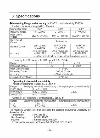
● Measuring Range and Accuracy (at 23±5℃, relative humidity 45-75%) Insulation Resistance Ranges:(IEC 61557-2)Nominal Output Voltage 250V 500V 1000VMeasuring RangesOpen-CircuitVoltageShort-Circuit Current
Nominal Current
Accuracy
0 - 100MΩ
250V DC +20% max.
1.3mA approx
1mA DC min.at 0.25MΩ
±5% of indicated valueat 0.1MΩ- 10MΩ±0.7% of scale length at ranges other than above ranges
0 - 200MΩ
500V DC +20% max.
1mA DC min.at 0.5MΩ
±5% of indicated valueat 0.2MΩ- 20MΩ
0 - 400MΩ
1000V DC + 20% max.
1mA DC min.at 1MΩ
±5% of indicated valueat 0.4MΩ- 40MΩ
Continuity Test (Resistance Test) Ranges:(IEC 61557-4)RangesMeasuring Ranges
x 1Ω0 - 2Ω
x 10Ω0 - 20Ω
Open-Circuit VoltageMeasuring CurrentAccuracyZero Adjustment Range
4 - 9V DC200mA DC min.
±3% of scale length0.2Ω min.
Ranges250V/100MΩ500V/200MΩ1000V/400MΩ
Measuring range to keep operating instrumetal uncertainty Maximum percentage operating instrumetal uncertainty0.1MΩ - 10MΩ
±30%0.2MΩ - 20MΩ0.4MΩ - 40MΩ
Rangesx1Ωx10Ω
Measuring range to keep operating instrumetal uncertainty Maximum percentage operating instrumetal uncertainty0.2Ω - 2Ω ±30%2Ω - 20Ω
Operating instrumetal uncertainty Insulation Resistance Ranges(IEC 61557-2)
Continuity Test (Resistance Test) Ranges(IEC 61557-4)
The influencing variations used for calculating the operating instrumental uncertainty are denoted as follows: Temperature : 0℃ and 35℃ Supply voltage : 6.5V to 10.4V Position : Reference position ±90° ※Prior to measurement, apply Zero Adjustment at each position

— 7 —
Typical Number of Measurements (central tendency for supply voltage up to 6.5V) Insulation Resistance Ranges: 1000V/400MΩ Range Approx. 500 times min. 500V/200MΩRange Approx. 1300 times min. 250V/100MΩ Range Approx. 1800 times min. Continuity Test (Resistance Test) Ranges: x1Ω Range/ x 10Ω Range Approx. 1000 times min.Applicable Standards IEC 61010-1. -2-030 Measurement CAT Ⅲ 300V Pollution Degree 2 IEC 61010-031 Safety requirements for hand-held probe assemblies IEC 61557-1,2,4 Measuring equipment for low voltage distribution systems IEC 61326-2-2 EMC IEC 60529 (IP54) Dust & drip proof EN 50581 (RoHS)Used location altitude 2000m or lessOperating Temperature & Humidity: 0-40℃, relative humidity up to 85%Storage Temperature & Humidity: -20-60℃, relative humidity up to 85%Insulation Resistance More than 50MΩat 1000V DC between
electrical circuit and housing caseWithstand Voltage 3470V AC for five seconds between electrical
circuit and housing caseOverload Protection Insulation resistance ranges: 1000V Range 1200V (DC) for 10 seconds 500V Range 600V (DC) for 10 seconds 250V Range 300V (DC) for 10 seconds Continuity ranges: x 1Ω/ x 10ΩRange 440V (AC p-p) for 1minuteDimensions: 185(L) x 167(W) x 89(D) mm approx.Weight: 860g approx. (including batteries)Power Source: 6 x 1.5V battery type SUM-3, R6 , AA or equivalentAccessories Test Probe MODEL7122B x 1 set Strap belt x 1 Test probe pouch x 1 R6P AA batteries x 6 Spare fuse F 500mA/600V x 1 Instruction manual x 1

— 8 —
4. Instrument Layout
①METER MOVEMENT ZERO ADJUST ②TEST BUTTON③SCALE PLATE ④LIVE CIRCUIT WARNING LED⑤POWER-ON INDICATION LED ⑥CONTINUITY ZERO ADJUST⑦LIGHT SWITCH ⑧RANGE SELECTOR SWITCH⑨TEST PROBE (RED) LINE PROBE ⑩TEST PROBE (BLACK) EARTH PROBE⑪ALLIGATOR CLIP (BLACK) ⑫PROTECTIVE FIGERGUARD
Fig.1 Part names

— 9 —
Protective fingerguard:It is a part providing protection against electrical shock and ensuring the minimum required air and creepage distances.
Cap:Uncapped condition for CAT.II environmentCapped condition for CAT.III/ IV environmentsThe Cap shuld be firmly attached to the probes.
Protective fingerguard Cap
— 10 —
5. Preparation for Testing
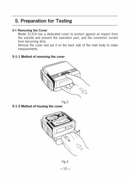
5-1 Removing the Cover Model 3131A has a dedicated cover to protect against an impact from
the outside and prevent the operation part, and the connector socket from becoming dirty.
Remove the cover and put it on the back side of the main body to make measurements.
5-1-1 Method of removing the cover
5-1-2 Method of housing the cover Fig.2
Fig.3
— 11 —
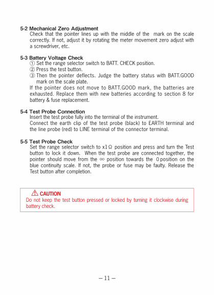
5-2 Mechanical Zero Adjustment Check that the pointer lines up with the middle of the mark on the scale
correctly. If not, adjust it by rotating the meter movement zero adjust with a screwdriver, etc.
5-3 Battery Voltage Check ① Set the range selector switch to BATT. CHECK position. ② Press the test button. ③ Then the pointer deflects. Judge the battery status with BATT.GOOD
mark on the scale plate. If the pointer does not move to BATT.GOOD mark, the batteries are
exhausted. Replace them with new batteries according to section 8 for battery & fuse replacement.
5-4 Test Probe Connection Insert the test probe fully into the terminal of the instrument. Connect the earth clip of the test probe (black) to EARTH terminal and
the line probe (red) to LINE terminal of the connector terminal.
5-5 Test Probe Check Set the range selector switch to x1Ω position and press and turn the Test
button to lock it down. When the test probe are connected together, the pointer should move from the ∞ position towards the 0position on the blue continuity scale. If not, the probe or fuse may be faulty. Release the Test button after completion.
# CAUTIONDo not keep the test button pressed or locked by turning it clockwise during battery check.

— 12 —
6-1 Disconnection and check of power source of circuit under test
# DANGER● To avoid possible electrical shock, do not perform measurements on
energized (LIVE) circuits.● Never make measurements with the battery compartment cover removed.● Always Keep your fingers and hands behind the protective fingerguard on
test probe to avoid the possible shock hazard.
# CAUTION● Never press the test button if the live circuit warning LED is lit or the
warning buzzer sounds. This may damage the circuit.
Voltage check can be made with the range selector switch at any position. Be sure to turn off the breaker for the circuit under test.① Connect the earth clip of the test probe (black) to the earth side and the line
probe (red) to the line side of the circuit under test.② Ensure that the live circuit warning LED is not lit and the audible warning
is not present. If the LED is lit and the buzzer sounds, never press the test button. Voltage is generated in the circuit under test. Recheck that the breaker for the circuit under test is "OFF".
6. Operation
Fig.4
E L

— 13 —
6-2 Insulation Resistance Measurement
# DANGER● Always test the circuit or equipment to ensure it is surely de-energized
before measurement according to the instruction of 6-1.● To avoid electrical shock, measurements must be performed on de-
energized circuits only.● When the test button is pressed with the range selector switch in the
insulation position, take care not to touch the tip of the test probe and the circuit under test where a high voltage is present in order to avoid possible shock hazard.
● Never make measurement with the battery compartment cover removed.● Always Keep your fingers and hands behind the protective fingerguard on
test probe to avoid the possible shock hazard.
# CAUTION● Never press the test button if the live circuit warning LED is lit or the
warning buzzer sounds. This may damage the circuit. Conduct the voltage warning check before measurement to ensure that
the circuit under test is de-energized.① Check the voltage which can be applied to the circuit under test and set
the range selector switch to the desired nominal output voltage range.② Connect the earth clip of the test probe (black) to the earth terminal of the
circuit under test.③ Put the tip of the line probe (red) to the circuit under test and press the
test button.④ Read the scale directly for the 500V range, multiply by 0.5 for 250V and
by 2 for 1000V.
Fig.5 Insulation resistance measurement
— 14 —
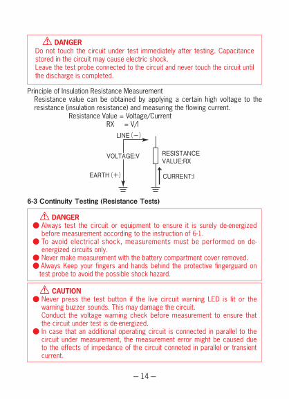
6-3 Continuity Testing (Resistance Tests)
# DANGER● Always test the circuit or equipment to ensure it is surely de-energized
before measurement according to the instruction of 6-1.● To avoid electrical shock, measurements must be performed on de-
energized circuits only.● Never make measurement with the battery compartment cover removed.● Always Keep your fingers and hands behind the protective fingerguard on
test probe to avoid the possible shock hazard.
# CAUTION● Never press the test button if the live circuit warning LED is lit or the
warning buzzer sounds. This may damage the circuit. Conduct the voltage warning check before measurement to ensure that
the circuit under test is de-energized.● In case that an additional operating circuit is connected in parallel to the
circuit under measurement, the measurement error might be caused due to the effects of impedance of the circuit conneted in parallel or transient current.
# DANGERDo not touch the circuit under test immediately after testing. Capacitance stored in the circuit may cause electric shock.Leave the test probe connected to the circuit and never touch the circuit until the discharge is completed.
Principle of Insulation Resistance Measurement Resistance value can be obtained by applying a certain high voltage to the
resistance (insulation resistance) and measuring the flowing current. Resistance Value = Voltage/Current RX = V/I
EARTH(+)
LINE(-)
VOLTAGE:V RESISTANCEVALUE:RX
CURRENT:I

— 15 —
6-4 Continuous Measurement A lock down feature is incorporated on the test button. Pressing and
turning it clockwise, lock the test button in the continuous operating position.
To release the lock turn the test button counterclockwise.
# DANGERBe extremely careful not to get electric shock during insulation resistance measurement as high voltage is present on the tip of the test probe continuously.
Principle of Continuity Testing (Resistance Test) Resistance value can be obtained by applying a certain current to the
resistance under test and measuring the voltage generated on the both sides of the resistance under test. Resistance Value = Voltage/Current RX = V/I
① Set the range selector switch to the desired position x 1Ωor x 10Ω.② Short the line probe (red) and the earth clip of the test probe (black) and
press the test button. Adjust the ohm zero adjust to zero the pointer on the scale.
③ Connect the test probes to the circuit under test and press the test button.④ Read the scale directly for x 1Ωrange, multiply by 10 for x 10Ωrange.
Fig.6

— 16 —
7. Back Light Function
To facilitate working at night or dimly lit situations, a back light function is provided which illuminates the display.To operate this function, the back light button must be pressed and released while pressing the test button. The back light continues illuminating for approx. 40 seconds and then turn off automatically.When the test button is released, the back light will turn off even within the lighting time.
Fig.7 How to use the back light button

— 17 —
8. Battery & Fuse Replacement
8-1 Battery Replacement ① Disconnect the test probe from the instrument. ② Open the battery compartment cover by unscrewing the metal captive
screw to reveal battery compartment. Always replace all six batteries with new ones at the same time.
Battery type: 6 x 1.5V battery type SUM-3, R6, AA or equivalent
8-2 Fuse Replacement ① Disconnect the test probe from the instrument. ② Open the battery compartment cover by unscrewing the metal captive
screw to reveal battery compartment and replace the fuse. Fuse type: F500mA/600V fast acting ceramic fuse φ6.35 x 32mm
Install batteries in correct polarity as marked inside the case.
# DANGER● Never open the battery compartment cover while making measurement. To avoid possible electrical shock, disconnect the test probe before
opening the cover for battery and fuse replacement.
● Replacement fuse must have the following rating. Fast acting type, F500mA/600V, φ6.35×32mm
Fig.8 How to replace batteries and fuse
SPARE FUSE
SCREW
FUSE
BATTERY
— 18 —
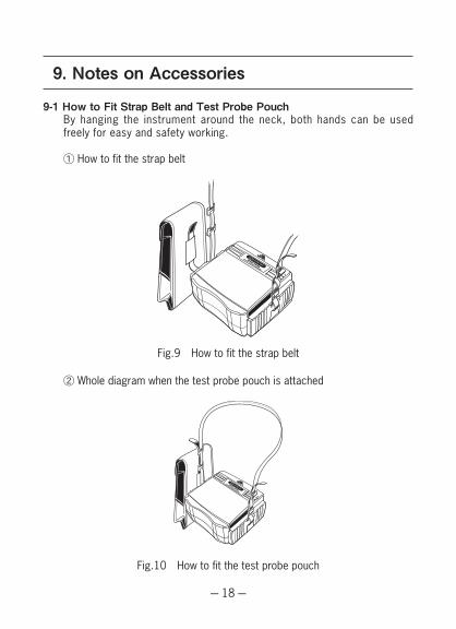
9. Notes on Accessories
9-1 How to Fit Strap Belt and Test Probe Pouch By hanging the instrument around the neck, both hands can be used
freely for easy and safety working.
① How to fit the strap belt
② Whole diagram when the test probe pouch is attached
Fig.9 How to fit the strap belt
Fig.10 How to fit the test probe pouch
— 19 —
10. Cleaning of the Instrument
◎ Cleaning the meter cover This instrument is managed by our company's quality standard and is
delivered in the best condition after passed the inspection. But in the dry time of winter static electricity sometimes builds up on the meter cover due to the characteristic of plastic.
When the pointer deflects by touching the surface of this instrument or zero adjustment can not be made, do not try to make measurement.
When static electricity builds up on the meter cover and affects the meter reading, use a cloth dampened with off-the-shelf anti-static agent or detergent to wipe the meter cover surface.
11. Service
If this tester should fail to operate correctly, return it to your nearest distributors stating the exact nature of the fault.Before returning the unit, make sure that: a) probes have been checked. b) fuse has been checked. c) battery has been checked.Remember, the more information written about the fault, the quicker it will be serviced.

— 20 —
MEMO


6-1892-1487E
DISTRIBUTOR
Kyoritsu reserves the rights to change specifications or designs described in this manual without notice and without obligations.