ViPER Video Performance Evaluation Toolkit viper-toolkit.sf.net.
Analog Mode (Viper & Automate)
INSTALLATION GUIDE
This product is intended for installation by a professional installer only! Attempts to install this product by a person other than a trained professional may result in severe damage to a vehicle’s electrical system and components.
2017-03-02
© 2017 Directed, Vista CA
DS4+
Designed by Installers for Installers
ContentsWarning! Safety first ....................................................................................................................... 3Introduction .................................................................................................................................... 4
Pre-installation and application warnings ..................................................................................... 4System compatibilities ................................................................................................................ 4What you get ........................................................................................................................... 4
Main module connections ................................................................................................................ 5Wiring connections ......................................................................................................................... 6
Main harness (H1), 12-pin black connector .................................................................................. 6Relay harness (H2), 10-pin white connector .................................................................................. 6Data harness (H3), 8-pin white connector ..................................................................................... 6Analog input/output harness (H4), 22-pin white connector ............................................................. 7RF Port harness (H5), 2-pin white connector .................................................................................. 7D2D harness (H6), 4-pin white (1) and black (2) connectors ........................................................... 7Temperature sensor harness (H7), 2-pin black connector (optional, 8556T) ....................................... 7
Installation ...................................................................................................................................... 8Configuring the system..................................................................................................................... 9
Important! ................................................................................................................................ 9RF Systems ............................................................................................................................... 98504D Combo Sensor ............................................................................................................... 9When used in conjunction with SmartStart .................................................................................... 9D2D port configuration ............................................................................................................ 10Module programming .............................................................................................................. 10LED diagnostics and troubleshooting .......................................................................................... 10Hard reset .............................................................................................................................. 11
Initializing Virtual Tach (not needed with hardwired or data tach applications) ..................................... 11Remote start shutdown/startup diagnostics ...................................................................................... 12
Shutdown diagnostics .............................................................................................................. 12Startup diagnostics .................................................................................................................. 12
Remote management ..................................................................................................................... 12Long-term event history (when security features are enabled) .............................................................. 13
Table of zones ........................................................................................................................ 13Troubleshooting ............................................................................................................................ 14
Alarm (when security features are enabled) ................................................................................ 14Remote start ............................................................................................................................ 14
Glossary of terms .......................................................................................................................... 16Limited lifetime consumer warranty .................................................................................................. 17Quick Reference Guide .................................................................................................................. 18
3 DS4+ Analog Mode (Viper & Automate)© 2017-03-02 Directed. All rights reserved.
Warning! Safety firstThe following safety warnings must be observed at all times:
• Due to the complexity of this system, installation of this product must only be performed by an authorized Directed dealer.• When properly installed, this system can start the vehicle via a command signal from the remote control. Therefore, never
operate the system in an area that does not have adequate ventilation.
The following precautions are the sole responsibility of the user; however, authorized Directed dealers should:• Never use a test light or logic probe when installing this unit. Always use a multimeter. • Never operate the system in an enclosed or partially enclosed area without ventilation (such as a garage). • USER MUST INSTALL A CARBON MONOXIDE DETECTOR IN OR ABOUT THE LIVING AREA ADJACENT TO THE VEHICLE.
ALL DOORS LEADING FROM ADJACENT LIVING AREAS TO THE ENCLOSED OR PARTIALLY ENCLOSED VEHICLE STORAGE AREA MUST REMAIN CLOSED AT ALL TIMES.
Use of this product in a manner contrary to its intended mode of operation may result in property damage, personal injury, or death. Except when performing the Safety Check outlined in this installation guide, (1) Never remotely start the vehicle with the vehicle in gear, and (2) Never remotely start the vehicle with the keys in the ignition. The user is responsible for having the neutral safety feature of the vehicle periodically checked, wherein the vehicle must not remotely start while the car is in gear. This testing should be performed by an authorized Directed dealer in accordance with the Safety Check outlined in this product installation guide. If the vehicle starts in gear, cease remote start operation immediately and consult with the user to fix the problem immediately.
OPERATION OF THE REMOTE START MODULE IF THE VEHICLE STARTS IN GEAR IS CONTRARY TO ITS INTENDED MODE OF OPERATION. OPERATING THE REMOTE START SYSTEM UNDER THESE CONDITIONS MAY RESULT IN PROPERTY DAMAGE OR PERSONAL INJURY. IMMEDIATELY CEASE THE USE OF THE UNIT AND REPAIR OR DISCONNECT THE INSTALLED REMOTE START MODULE. DIRECTED WILL NOT BE HELD RESPONSIBLE OR PAY FOR INSTALLATION OR REINSTALLATION COSTS.
Remote starters for manual transmission pose significant risks if not properly installed and operated. When testing to ensure the installation is working properly, only remote start the vehicle in neutral gear, on a flat surface and with a functional, fully engaged parking brake. Do not allow anyone to stand in front of or behind the vehicle.
This product should not be installed in any convertible vehicles, soft or hard top with a manual transmission. Installation in such vehicles may pose certain risk.
4 DS4+ Analog Mode (Viper & Automate)© 2017-03-02 Directed. All rights reserved.
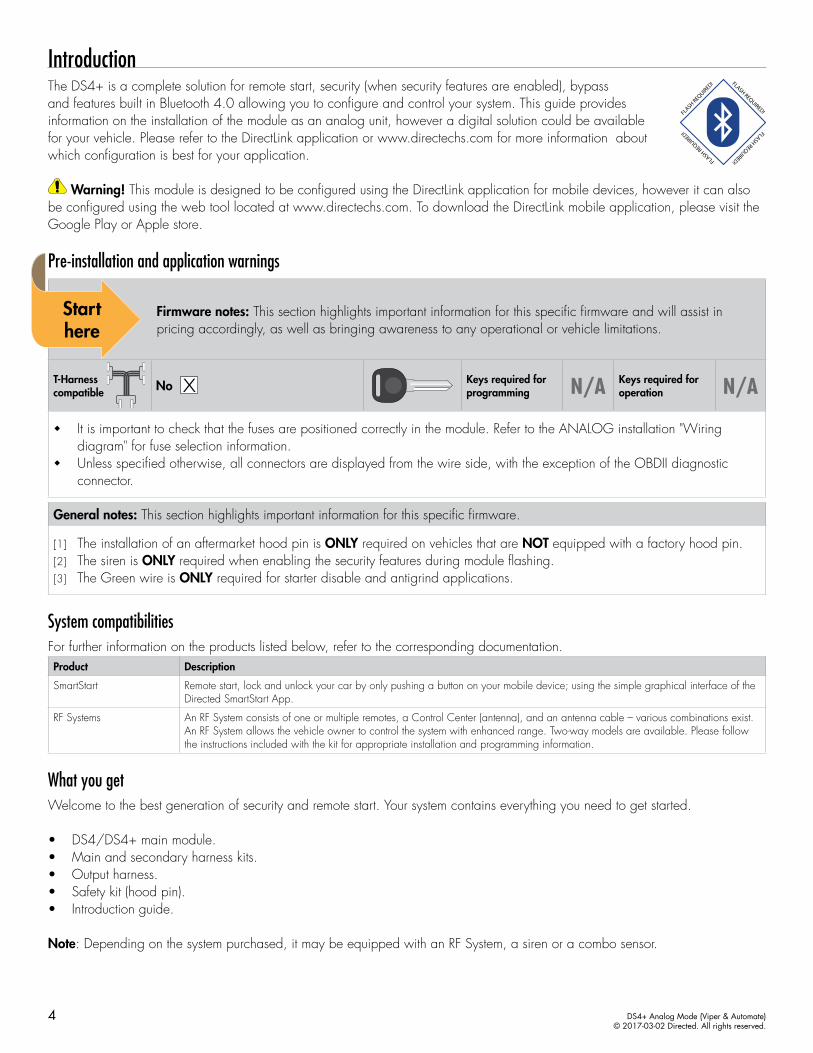
IntroductionThe DS4+ is a complete solution for remote start, security (when security features are enabled), bypass and features built in Bluetooth 4.0 allowing you to configure and control your system. This guide provides information on the installation of the module as an analog unit, however a digital solution could be available for your vehicle. Please refer to the DirectLink application or www.directechs.com for more information about which configuration is best for your application.
Warning! This module is designed to be configured using the DirectLink application for mobile devices, however it can also be configured using the web tool located at www.directechs.com. To download the DirectLink mobile application, please visit the Google Play or Apple store.
Pre-installation and application warnings
Firmware notes: This section highlights important information for this specific firmware and will assist in pricing accordingly, as well as bringing awareness to any operational or vehicle limitations.
T-Harness compatible
Keys required for programming N/A Keys required for
operation N/A
� It is important to check that the fuses are positioned correctly in the module. Refer to the ANALOG installation "Wiring diagram" for fuse selection information.
� Unless specified otherwise, all connectors are displayed from the wire side, with the exception of the OBDII diagnostic connector.
General notes: This section highlights important information for this specific firmware.
[1] The installation of an aftermarket hood pin is ONLY required on vehicles that are NOT equipped with a factory hood pin.[2] The siren is ONLY required when enabling the security features during module flashing.[3] The Green wire is ONLY required for starter disable and antigrind applications.
System compatibilitiesFor further information on the products listed below, refer to the corresponding documentation.Product Description
SmartStart Remote start, lock and unlock your car by only pushing a button on your mobile device; using the simple graphical interface of the Directed SmartStart App.
RF Systems An RF System consists of one or multiple remotes, a Control Center (antenna), and an antenna cable – various combinations exist. An RF System allows the vehicle owner to control the system with enhanced range. Two-way models are available. Please follow the instructions included with the kit for appropriate installation and programming information.
What you getWelcome to the best generation of security and remote start. Your system contains everything you need to get started.
• DS4/DS4+ main module.• Main and secondary harness kits.• Output harness.• Safety kit (hood pin).• Introduction guide.
Note: Depending on the system purchased, it may be equipped with an RF System, a siren or a combo sensor.
5 DS4+ Analog Mode (Viper & Automate)© 2017-03-02 Directed. All rights reserved.
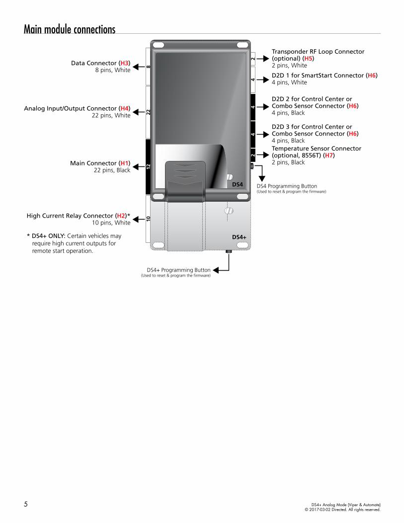
Main module connections
228
1012
42
44
2
DS4+
DS4
Transponder RF Loop Connector (optional) (H5)2 pins, White
Analog Input/Output Connector (H4)22 pins, White
Data Connector (H3)8 pins, White
Main Connector (H1)22 pins, Black
High Current Relay Connector (H2)*10 pins, White
DS4+ Programming Button(Used to reset & program the firmware)
DS4 Programming Button(Used to reset & program the firmware)
D2D 3 for Control Center or Combo Sensor Connector (H6)4 pins, Black
D2D 2 for Control Center or Combo Sensor Connector (H6)4 pins, Black
D2D 1 for SmartStart Connector (H6)4 pins, White
Temperature Sensor Connector (optional, 8556T) (H7)2 pins, Black
* DS4+ ONLY: Certain vehicles may require high current outputs for remote start operation.
6 DS4+ Analog Mode (Viper & Automate)© 2017-03-02 Directed. All rights reserved.
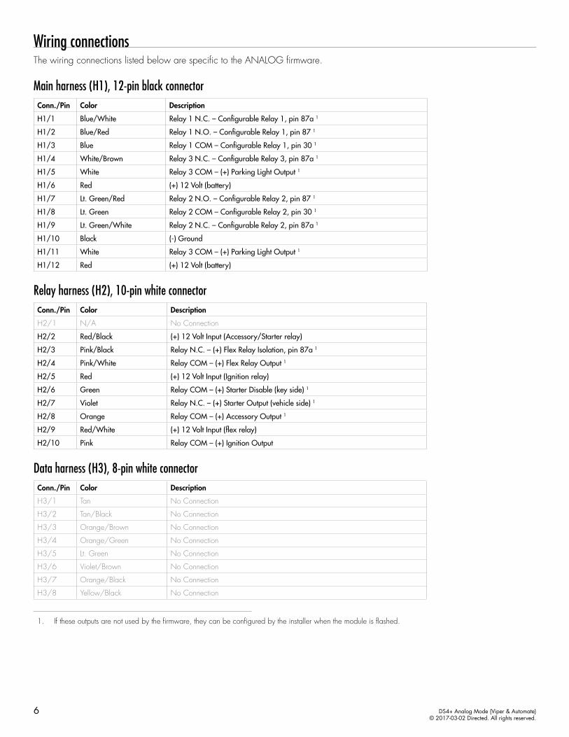
Wiring connectionsThe wiring connections listed below are specific to the ANALOG firmware.
Main harness (H1), 12-pin black connectorConn./Pin Color Description
H1/1 Blue/White Relay 1 N.C. – Configurable Relay 1, pin 87a 1
H1/2 Blue/Red Relay 1 N.O. – Configurable Relay 1, pin 87 1
H1/3 Blue Relay 1 COM – Configurable Relay 1, pin 30 1
H1/4 White/Brown Relay 3 N.C. – Configurable Relay 3, pin 87a 1
H1/5 White Relay 3 COM – (+) Parking Light Output 1
H1/6 Red (+) 12 Volt (battery)
H1/7 Lt. Green/Red Relay 2 N.O. – Configurable Relay 2, pin 87 1
H1/8 Lt. Green Relay 2 COM – Configurable Relay 2, pin 30 1
H1/9 Lt. Green/White Relay 2 N.C. – Configurable Relay 2, pin 87a 1
H1/10 Black (-) Ground
H1/11 White Relay 3 COM – (+) Parking Light Output 1
H1/12 Red (+) 12 Volt (battery)
Relay harness (H2), 10-pin white connectorConn./Pin Color Description
H2/1 N/A No Connection
H2/2 Red/Black (+) 12 Volt Input (Accessory/Starter relay)
H2/3 Pink/Black Relay N.C. – (+) Flex Relay Isolation, pin 87a 1
H2/4 Pink/White Relay COM – (+) Flex Relay Output 1
H2/5 Red (+) 12 Volt Input (Ignition relay)
H2/6 Green Relay COM – (+) Starter Disable (key side) 1
H2/7 Violet Relay N.C. – (+) Starter Output (vehicle side) 1
H2/8 Orange Relay COM – (+) Accessory Output 1
H2/9 Red/White (+) 12 Volt Input (flex relay)
H2/10 Pink Relay COM – (+) Ignition Output
Data harness (H3), 8-pin white connectorConn./Pin Color Description
H3/1 Tan No Connection
H3/2 Tan/Black No Connection
H3/3 Orange/Brown No Connection
H3/4 Orange/Green No Connection
H3/5 Lt. Green No Connection
H3/6 Violet/Brown No Connection
H3/7 Orange/Black No Connection
H3/8 Yellow/Black No Connection
1. If these outputs are not used by the firmware, they can be configured by the installer when the module is flashed.
7 DS4+ Analog Mode (Viper & Automate)© 2017-03-02 Directed. All rights reserved.
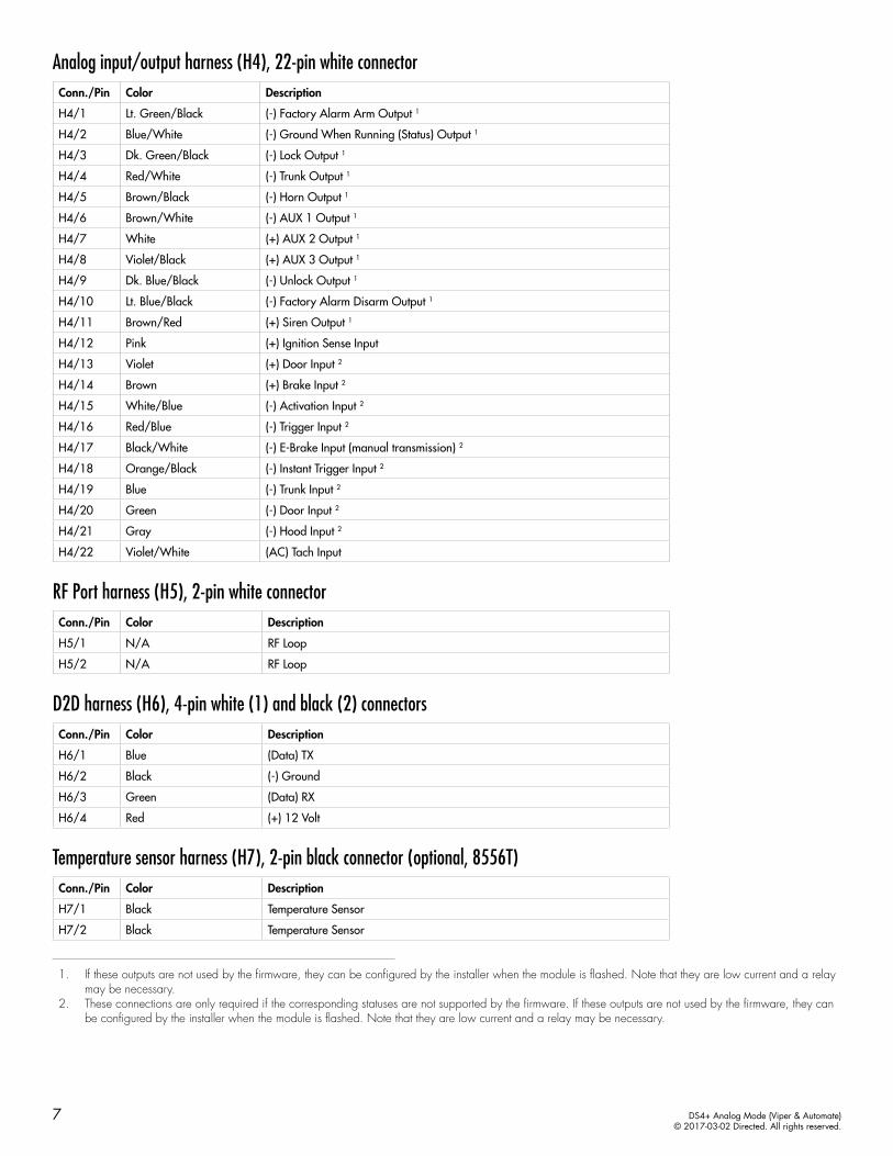
Analog input/output harness (H4), 22-pin white connectorConn./Pin Color Description
H4/1 Lt. Green/Black (-) Factory Alarm Arm Output 1
H4/2 Blue/White (-) Ground When Running (Status) Output 1
H4/3 Dk. Green/Black (-) Lock Output 1
H4/4 Red/White (-) Trunk Output 1
H4/5 Brown/Black (-) Horn Output 1
H4/6 Brown/White (-) AUX 1 Output 1
H4/7 White (+) AUX 2 Output 1
H4/8 Violet/Black (+) AUX 3 Output 1
H4/9 Dk. Blue/Black (-) Unlock Output 1
H4/10 Lt. Blue/Black (-) Factory Alarm Disarm Output 1
H4/11 Brown/Red (+) Siren Output 1
H4/12 Pink (+) Ignition Sense Input
H4/13 Violet (+) Door Input 2
H4/14 Brown (+) Brake Input 2
H4/15 White/Blue (-) Activation Input 2
H4/16 Red/Blue (-) Trigger Input 2
H4/17 Black/White (-) E-Brake Input (manual transmission) 2
H4/18 Orange/Black (-) Instant Trigger Input 2
H4/19 Blue (-) Trunk Input 2
H4/20 Green (-) Door Input 2
H4/21 Gray (-) Hood Input 2
H4/22 Violet/White (AC) Tach Input
RF Port harness (H5), 2-pin white connectorConn./Pin Color Description
H5/1 N/A RF Loop
H5/2 N/A RF Loop
D2D harness (H6), 4-pin white (1) and black (2) connectorsConn./Pin Color Description
H6/1 Blue (Data) TX
H6/2 Black (-) Ground
H6/3 Green (Data) RX
H6/4 Red (+) 12 Volt
Temperature sensor harness (H7), 2-pin black connector (optional, 8556T)Conn./Pin Color Description
H7/1 Black Temperature Sensor
H7/2 Black Temperature Sensor
1. If these outputs are not used by the firmware, they can be configured by the installer when the module is flashed. Note that they are low current and a relay may be necessary.
2. These connections are only required if the corresponding statuses are not supported by the firmware. If these outputs are not used by the firmware, they can be configured by the installer when the module is flashed. Note that they are low current and a relay may be necessary.
8 DS4+ Analog Mode (Viper & Automate)© 2017-03-02 Directed. All rights reserved.
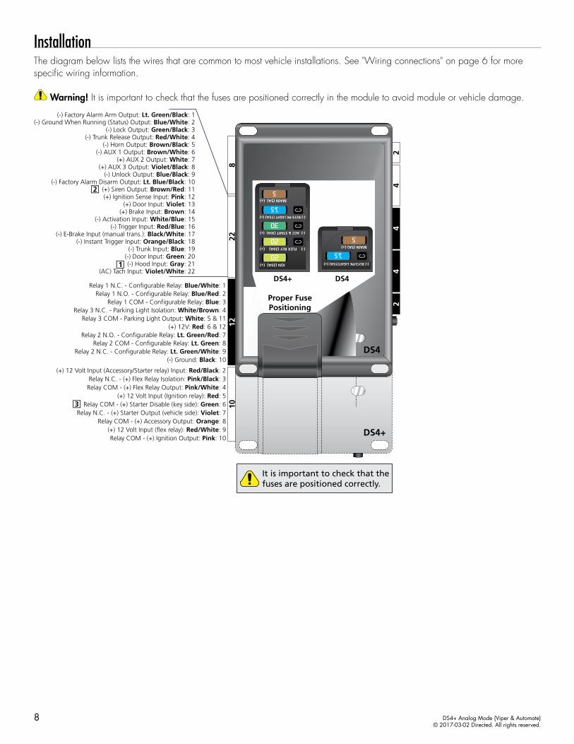
InstallationThe diagram below lists the wires that are common to most vehicle installations. See "Wiring connections" on page 6 for more specific wiring information.
Warning! It is important to check that the fuses are positioned correctly in the module to avoid module or vehicle damage.
228
1012
42
44
2
DS4+
DS4
(+) 12 Volt Input (flex relay): Red/White: 9
Relay N.C. - (+) Starter Output (vehicle side): Violet: 7
Relay COM - (+) Ignition Output: Pink: 10
(-) Ground: Black: 10
Relay COM - (+) Accessory Output: Orange: 8
(+) 12 Volt Input (Accessory/Starter relay) Input: Red/Black: 2
Relay COM - (+) Flex Relay Output: Pink/White: 4Relay N.C. - (+) Flex Relay Isolation: Pink/Black: 3
(+) 12 Volt Input (Ignition relay): Red: 5
(+) 12V: Red: 6 & 12Relay 3 COM - Parking Light Output: White: 5 & 11
Relay 1 N.C. - Configurable Relay: Blue/White: 1Relay 1 N.O. - Configurable Relay: Blue/Red: 2
Relay 1 COM - Configurable Relay: Blue: 3Relay 3 N.C. - Parking Light Isolation: White/Brown: 4
Relay 2 N.O. - Configurable Relay: Lt. Green/Red: 7Relay 2 COM - Configurable Relay: Lt. Green: 8
Relay 2 N.C. - Configurable Relay: Lt. Green/White: 9
Relay COM - (+) Starter Disable (key side): Green: 6
(-) Factory Alarm Arm Output: Lt. Green/Black: 1
(-) Factory Alarm Disarm Output: Lt. Blue/Black: 10
(-) E-Brake Input (manual trans.): Black/White: 17(-) Instant Trigger Input: Orange/Black: 18
(-) Trunk Input: Blue: 19
(-) Hood Input: Gray: 21(AC) Tach Input: Violet/White: 22
(-) Unlock Output: Blue/Black: 9
(-) Horn Output: Brown/Black: 5(-) AUX 1 Output: Brown/White: 6
(+) AUX 2 Output: White: 7(+) AUX 3 Output: Violet/Black: 8
(-) Trunk Release Output: Red/White: 4
(-) Door Input: Green: 20
(+) Door Input: Violet: 13
(-) Lock Output: Green/Black: 3
(+) Brake Input: Brown: 14(-) Activation Input: White/Blue: 15
(-) Trigger Input: Red/Blue: 16
(+) Siren Output: Brown/Red: 11(+) Ignition Sense Input: Pink: 12
(-) Ground When Running (Status) Output: Blue/White: 2
Proper FusePositioning
DS4+ DS4
5
15
5
15MAIN (5A) (+)
(-) RLY3/PK LIGHT(15A) (+)
MAIN (5A) (+)
(-) RLY3/PK LIGHT(15A) (+)
5
15
30
20
20
5
15
30
20
20
5
15
30
20
20
5
15
30
20
20
5
15
30
20
20
5
15
30
20
20
MAIN (5A) (+)
(-) RLY3 PK LIGHT (15A) (+)
(-) ACC & START (30A) (+)
(-) FLEX RLY (20A) (+)
IGN (20A) (+)
MAIN (5A) (+)
(-) RLY3 PK LIGHT (15A) (+)
(-) ACC & START (30A) (+)
(-) FLEX RLY (20A) (+)
IGN (20A) (+)
MAIN (5A) (+)
(-) RLY3 PK LIGHT (15A) (+)
(-) ACC & START (30A) (+)
(-) FLEX RLY (20A) (+)
IGN (20A) (+)
MAIN (5A) (+)
(-) RLY3 PK LIGHT (15A) (+)
(-) ACC & START (30A) (+)
(-) FLEX RLY (20A) (+)
IGN (20A) (+)
MAIN (5A) (+)
(-) RLY3 PK LIGHT (15A) (+)
(-) ACC & START (30A) (+)
(-) FLEX RLY (20A) (+)
IGN (20A) (+)
MAIN (5A) (+)
(-) RLY3 PK LIGHT (15A) (+)
(-) ACC & START (30A) (+)
(-) FLEX RLY (20A) (+)
IGN (20A) (+)It is important to check that the fuses are positioned correctly.
9 DS4+ Analog Mode (Viper & Automate)© 2017-03-02 Directed. All rights reserved.
Configuring the system
Important!Once the DS4+ module is installed in the vehicle following the instructions in "Installation" on page 8, launch the DirectLink application on your mobile device, and select Configure DS4/DS4+. Follow the on-screen instructions to configure the system.
Note: Your system can also be configured using XKLoader2 on www.directechs.com.
Vehicles equipped with a manual transmissionAdditional connections may be required if these functions are not supported by the firmware.Connection Description
(-) E-Brake Status Input (Black/White, pin 17)
Must be connected to a working emergency brake in the vehicle. Although most vehicles have simple (-) trigger emergency brake circuits note some vehicles do not and may require unique integration methodologies.
(-) Door Trigger Input (Green, pin 20) OR (+) Door Input (Violet, pin 13)
Must be connected to a working door trigger in the vehicle, which monitors all doors. The unit must monitor the door pins to allow the Ready Mode process to be enabled.Note: Some vehicles may require unique integration methodologies for this circuit. For more information, refer to www.directechs.com.
(AC) Tachometer Input (Violet/White, pin 22)
Must be connected to a working tachometer signal in the vehicle (fuel injector, ignition coil, true tach, etc.) and learned successfully to the DS4+.
RF SystemsAn RF System consists of one or multiple remotes, a Control Center (antenna), and an antenna cable – various combinations exist. An RF System allows the vehicle owner to control the system with enhanced range. Two-way models are available. Please follow the instructions included with the kit for appropriate installation and programming information.
8504D Combo SensorThe 8504D Combo Sensor must be paired to the device before it can be used. To enter pairing, turn the vehicle ignition to the ON position, then press and hold the programming button on the Control Center (antenna) until the LED starts flashing. Once pairing mode has been entered, your Combo Sensor is ready to use.
Your Combo Sensor is preset for the majority of applications, however it can be adjusted using the DirectLink application, as well as a compatible LED or LCD remote. Please refer to the instructions included with your sensor for more information on how to make adjustments.
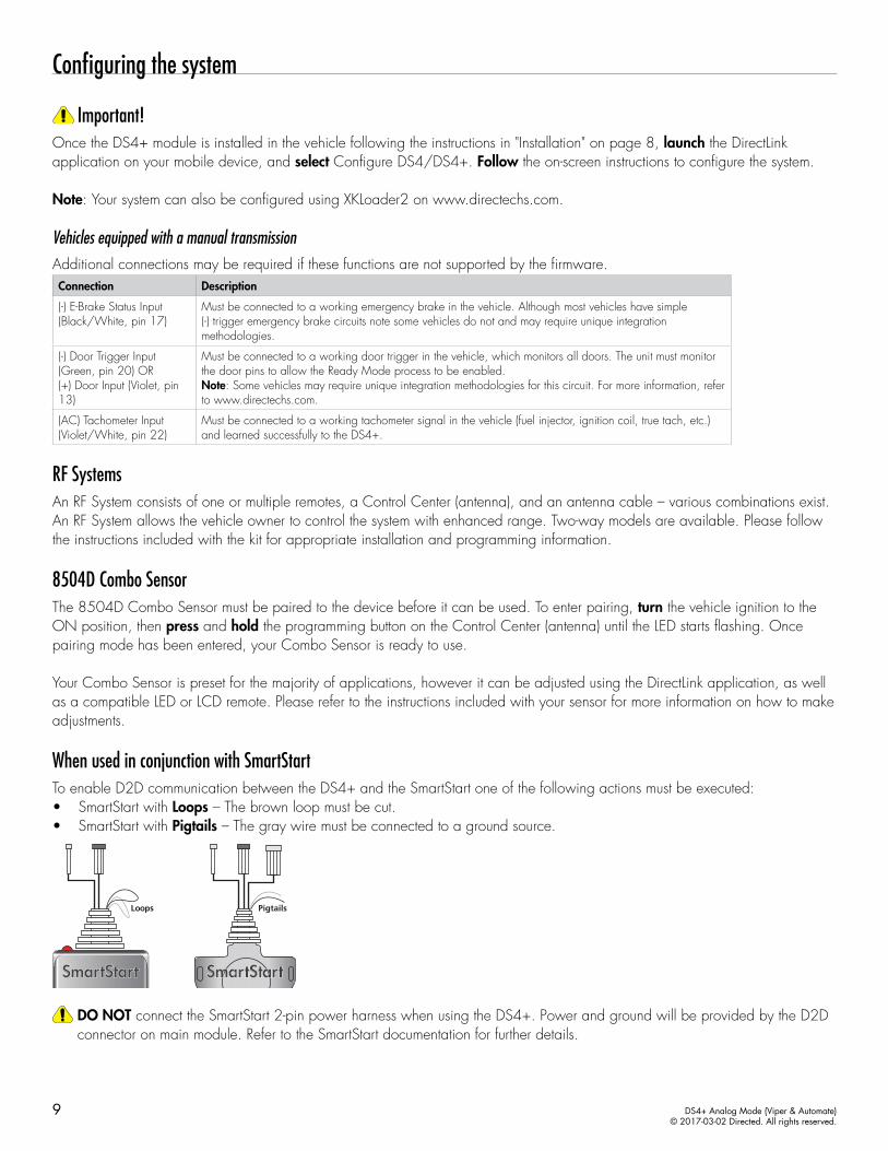
When used in conjunction with SmartStartTo enable D2D communication between the DS4+ and the SmartStart one of the following actions must be executed:• SmartStart with Loops – The brown loop must be cut. • SmartStart with Pigtails – The gray wire must be connected to a ground source.
Loops Pigtails
THIS SIDE UP
DO NOT connect the SmartStart 2-pin power harness when using the DS4+. Power and ground will be provided by the D2D connector on main module. Refer to the SmartStart documentation for further details.
10 DS4+ Analog Mode (Viper & Automate)© 2017-03-02 Directed. All rights reserved.
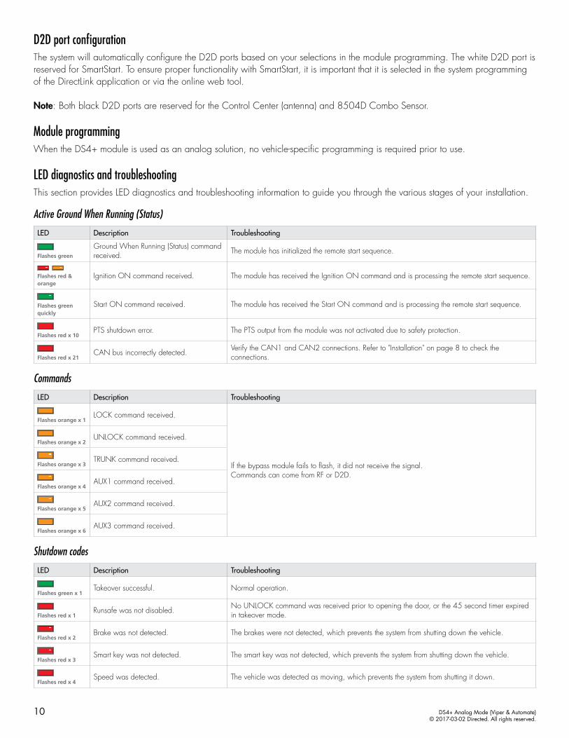
D2D port configurationThe system will automatically configure the D2D ports based on your selections in the module programming. The white D2D port is reserved for SmartStart. To ensure proper functionality with SmartStart, it is important that it is selected in the system programming of the DirectLink application or via the online web tool.
Note: Both black D2D ports are reserved for the Control Center (antenna) and 8504D Combo Sensor.
Module programmingWhen the DS4+ module is used as an analog solution, no vehicle-specific programming is required prior to use.
LED diagnostics and troubleshootingThis section provides LED diagnostics and troubleshooting information to guide you through the various stages of your installation.
Active Ground When Running (Status)
LED Description Troubleshooting
Flashes green
Ground When Running (Status) command received. The module has initialized the remote start sequence.
Flashes red & orange
Ignition ON command received. The module has received the Ignition ON command and is processing the remote start sequence.
Flashes green quickly
Start ON command received. The module has received the Start ON command and is processing the remote start sequence.
Flashes red x 10PTS shutdown error. The PTS output from the module was not activated due to safety protection.
Flashes red x 21CAN bus incorrectly detected. Verify the CAN1 and CAN2 connections. Refer to "Installation" on page 8 to check the
connections.
Commands
LED Description Troubleshooting
Flashes orange x 1LOCK command received.
If the bypass module fails to flash, it did not receive the signal. Commands can come from RF or D2D.
Flashes orange x 2UNLOCK command received.
Flashes orange x 3TRUNK command received.
Flashes orange x 4AUX1 command received.
Flashes orange x 5AUX2 command received.
Flashes orange x 6AUX3 command received.
Shutdown codes
LED Description Troubleshooting
Flashes green x 1Takeover successful. Normal operation.
Flashes red x 1Runsafe was not disabled. No UNLOCK command was received prior to opening the door, or the 45 second timer expired
in takeover mode.
Flashes red x 2Brake was not detected. The brakes were not detected, which prevents the system from shutting down the vehicle.
Flashes red x 3Smart key was not detected. The smart key was not detected, which prevents the system from shutting down the vehicle.
Flashes red x 4Speed was detected. The vehicle was detected as moving, which prevents the system from shutting it down.
11 DS4+ Analog Mode (Viper & Automate)© 2017-03-02 Directed. All rights reserved.
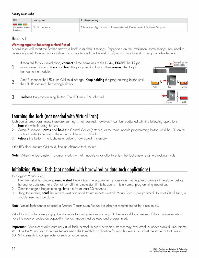
Analog error codes
LED Description Troubleshooting
Flashes red, green & orange
DEI feature error. A feature config file mismatch was detected. Please contact Technical Support.
Hard resetWarning Against Executing a Hard Reset! A hard reset will revert the flashed firmware back to its default settings. Depending on the installation, some settings may need to be reconfigured. Connect your module to a computer and use the web configuration tool to edit its programmable features.
1If required for your installation, connect all the harnesses to the DS4+, EXCEPT the 12-pin main power harness. Press and hold the programming button, then connect the 12-pin harness to the module.
Connect all but the 12-pin harness
2 After 3 seconds the LED turns ON solid orange. Keep holding the programming button until the LED flashes red, then orange slowly.
HoldSolid Flashes
&&
3 Release the programming button. The LED turns ON solid red. &Release Solid
Learning the Tach (not needed with Virtual Tach)Tach comes preprogrammed, therefore learning is not required; however, it can be readjusted with the following operations: 1. Start the vehicle using the key. 2. Within 5 seconds, press and hold the Control Center (antenna) or the main module programming button, until the LED on the
Control Center (antenna) or the main module turns ON solid.3. Release the button. The tachometer value is now stored in memory.
If the LED does not turn ON solid, find an alternate tach source.
Note: When the tachometer is programmed, the main module automatically enters the Tachometer engine checking mode.
Initializing Virtual Tach (not needed with hardwired or data tach applications)To program Virtual Tach:1. After the install is complete, remote start the engine. The programming operation may require 3 cranks of the starter before
the engine starts and runs. Do not turn off the remote start if this happens, it is a normal programming operation.2. Once the engine begins running, let it run for at least 30 seconds.3. Using the remote, send the Remote start command to turn remote start off. Virtual Tach is programmed. To reset Virtual Tach, a
module reset must be done.
Note: Virtual Tach cannot be used in Manual Transmission Mode. It is also not recommended for diesel trucks.
Virtual Tach handles disengaging the starter motor during remote starting – it does not address over-rev. If the customer wants to have the over-rev protection capability, the tach mode must be used and programmed.
Important! After successfully learning Virtual Tach, a small minority of vehicle starters may over crank or under crank during remote start. Use the Virtual Tach Fine tune feature using the DirectLink application for mobile devices to adjust the starter output time in 50mS increments to compensate for such an occurrence.
12 DS4+ Analog Mode (Viper & Automate)© 2017-03-02 Directed. All rights reserved.
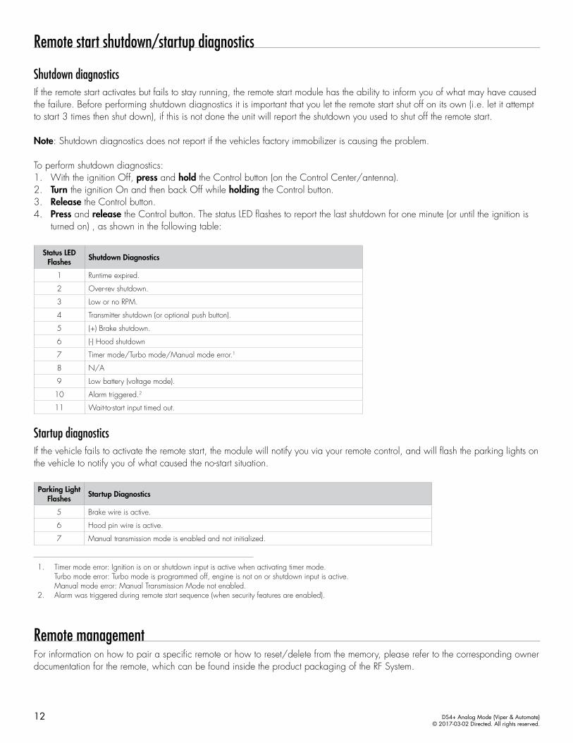
Remote start shutdown/startup diagnostics
Shutdown diagnosticsIf the remote start activates but fails to stay running, the remote start module has the ability to inform you of what may have caused the failure. Before performing shutdown diagnostics it is important that you let the remote start shut off on its own (i.e. let it attempt to start 3 times then shut down), if this is not done the unit will report the shutdown you used to shut off the remote start.
Note: Shutdown diagnostics does not report if the vehicles factory immobilizer is causing the problem.
To perform shutdown diagnostics:1. With the ignition Off, press and hold the Control button (on the Control Center/antenna).2. Turn the ignition On and then back Off while holding the Control button.3. Release the Control button.4. Press and release the Control button. The status LED flashes to report the last shutdown for one minute (or until the ignition is
turned on) , as shown in the following table:
Status LED Flashes Shutdown Diagnostics
1 Runtime expired.
2 Over-rev shutdown.
3 Low or no RPM.
4 Transmitter shutdown (or optional push button).
5 (+) Brake shutdown.
6 (-) Hood shutdown
7 Timer mode/Turbo mode/Manual mode error.1
8 N/A
9 Low battery (voltage mode).
10 Alarm triggered.2
11 Wait-to-start input timed out.
Startup diagnosticsIf the vehicle fails to activate the remote start, the module will notify you via your remote control, and will flash the parking lights on the vehicle to notify you of what caused the no-start situation.
Parking Light Flashes Startup Diagnostics
5 Brake wire is active.
6 Hood pin wire is active.
7 Manual transmission mode is enabled and not initialized.
1. Timer mode error: Ignition is on or shutdown input is active when activating timer mode. Turbo mode error: Turbo mode is programmed off, engine is not on or shutdown input is active. Manual mode error: Manual Transmission Mode not enabled.
2. Alarm was triggered during remote start sequence (when security features are enabled).
Remote managementFor information on how to pair a specific remote or how to reset/delete from the memory, please refer to the corresponding owner documentation for the remote, which can be found inside the product packaging of the RF System.
13 DS4+ Analog Mode (Viper & Automate)© 2017-03-02 Directed. All rights reserved.
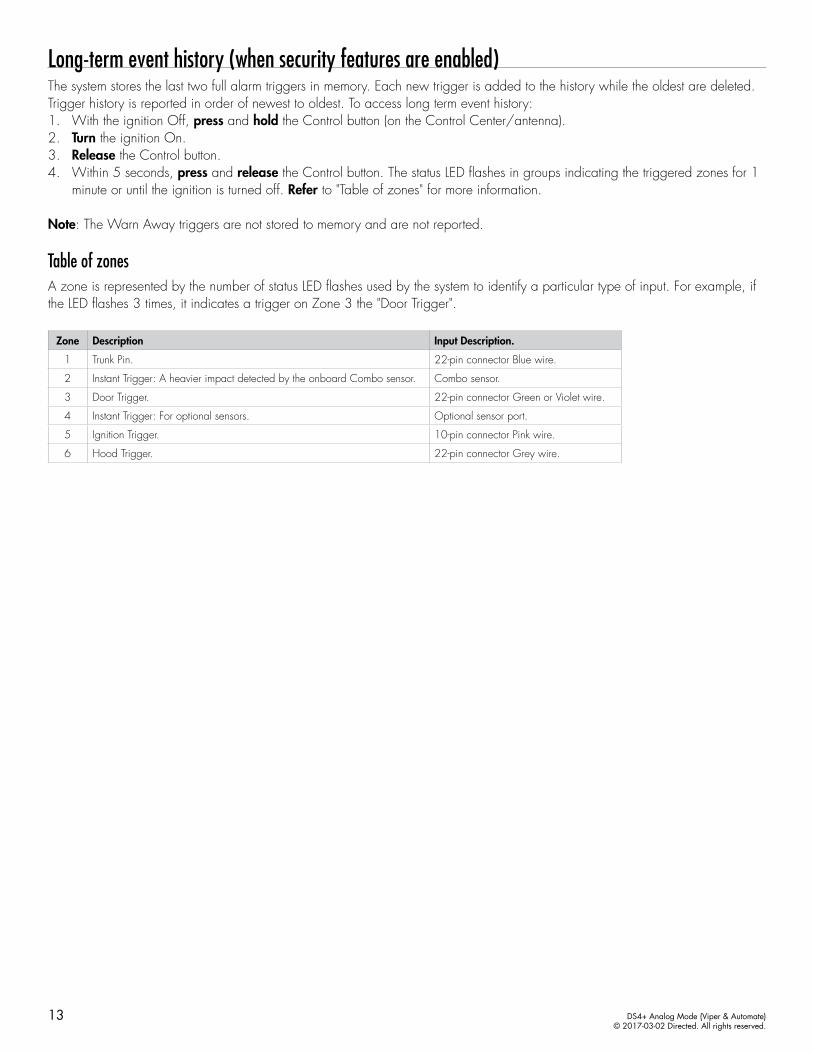
Long-term event history (when security features are enabled)The system stores the last two full alarm triggers in memory. Each new trigger is added to the history while the oldest are deleted. Trigger history is reported in order of newest to oldest. To access long term event history:1. With the ignition Off, press and hold the Control button (on the Control Center/antenna).2. Turn the ignition On.3. Release the Control button.4. Within 5 seconds, press and release the Control button. The status LED flashes in groups indicating the triggered zones for 1
minute or until the ignition is turned off. Refer to "Table of zones" for more information.
Note: The Warn Away triggers are not stored to memory and are not reported.
Table of zonesA zone is represented by the number of status LED flashes used by the system to identify a particular type of input. For example, if the LED flashes 3 times, it indicates a trigger on Zone 3 the "Door Trigger".
Zone Description Input Description.
1 Trunk Pin. 22-pin connector Blue wire.
2 Instant Trigger: A heavier impact detected by the onboard Combo sensor. Combo sensor.
3 Door Trigger. 22-pin connector Green or Violet wire.
4 Instant Trigger: For optional sensors. Optional sensor port.
5 Ignition Trigger. 10-pin connector Pink wire.
6 Hood Trigger. 22-pin connector Grey wire.
14 DS4+ Analog Mode (Viper & Automate)© 2017-03-02 Directed. All rights reserved.
Troubleshooting
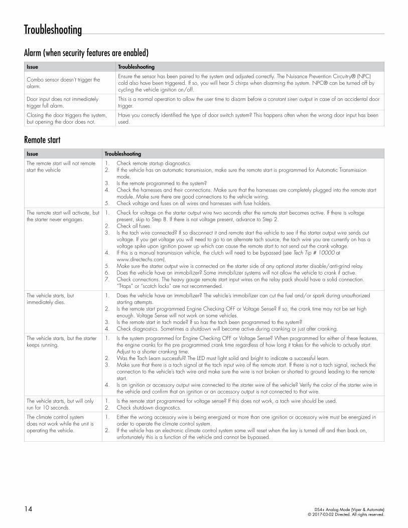
Alarm (when security features are enabled)Issue Troubleshooting
Combo sensor doesn’t trigger the alarm.
Ensure the sensor has been paired to the system and adjusted correctly. The Nuisance Prevention Circuitry® (NPC) cold also have been triggered. If so, you will hear 5 chirps when disarming the system. NPC® can be turned off by cycling the vehicle ignition on/off.
Door input does not immediately trigger full alarm.
This is a normal operation to allow the user time to disarm before a constant siren output in case of an accidental door trigger.
Closing the door triggers the system, but opening the door does not.
Have you correctly identified the type of door switch system? This happens often when the wrong door input has been used.
Remote startIssue Troubleshooting
The remote start will not remote start the vehicle
1. Check remote startup diagnostics.2. If the vehicle has an automatic transmission, make sure the remote start is programmed for Automatic Transmission
mode.3. Is the remote programmed to the system?4. Check the harnesses and their connections. Make sure that the harnesses are completely plugged into the remote start
module. Make sure there are good connections to the vehicle wiring.5. Check voltage and fuses on all wires and harnesses with fuse holders.
The remote start will activate, but the starter never engages.
1. Check for voltage on the starter output wire two seconds after the remote start becomes active. If there is voltage present, skip to Step 8. If there is not voltage present, advance to Step 2.
2. Check all fuses. 3. Is the tach wire connected? If so disconnect it and remote start the vehicle to see if the starter output wire sends out
voltage. If you get voltage you will need to go to an alternate tach source, the tach wire you are currently on has a voltage spike upon ignition power up which can cause the remote start to not send out the crank voltage.
4. If this is a manual transmission vehicle, the clutch will need to be bypassed (see Tech Tip # 10000 at www.directechs.com).
5. Make sure the starter output wire is connected on the starter side of any optional starter disable/anti-grind relay.6. Does the vehicle have an immobilizer? Some immobilizer systems will not allow the vehicle to crank if active.7. Check connections. The heavy gauge remote start input wires on the relay pack should have a solid connection.
“T-taps” or “scotch locks” are not recommended.
The vehicle starts, but immediately dies.
1. Does the vehicle have an immobilizer? The vehicle’s immobilizer can cut the fuel and/or spark during unauthorized starting attempts.
2. Is the remote start programmed Engine Checking OFF or Voltage Sense? If so, the crank time may not be set high enough. Voltage Sense will not work on some vehicles.
3. Is the remote start in tach mode? If so has the tach been programmed to the system?4. Check diagnostics. Sometimes a shutdown will become active during cranking or just after cranking.
The vehicle starts, but the starter keeps running.
1. Is the system programmed for Engine Checking OFF or Voltage Sense? When programmed for either of these features, the engine cranks for the pre programmed crank time regardless of how long it takes for the vehicle to actually start. Adjust to a shorter cranking time.
2. Was the Tach Learn successful? The LED must light solid and bright to indicate a successful learn.3. Make sure that there is a tach signal at the tach input wire of the remote start. If there is not a tach signal, recheck the
connection to the vehicle’s tach wire and make sure the wire is not broken or shorted to ground leading to the remote start.
4. Is an ignition or accessory output wire connected to the starter wire of the vehicle? Verify the color of the starter wire in the vehicle and confirm that an ignition or an accessory output is not connected to that wire.
The vehicle starts, but will only run for 10 seconds.
1. Is the remote start programmed for voltage sense? If this does not work, a tach wire should be used.2. Check shutdown diagnostics.
The climate control system does not work while the unit is operating the vehicle.
1. Either the wrong accessory wire is being energized or more than one ignition or accessory wire must be energized in order to operate the climate control system.
2. If the vehicle has an electronic climate control system some will reset when the key is turned off and then back on, unfortunately this is a function of the vehicle and cannot be bypassed.
15 DS4+ Analog Mode (Viper & Automate)© 2017-03-02 Directed. All rights reserved.
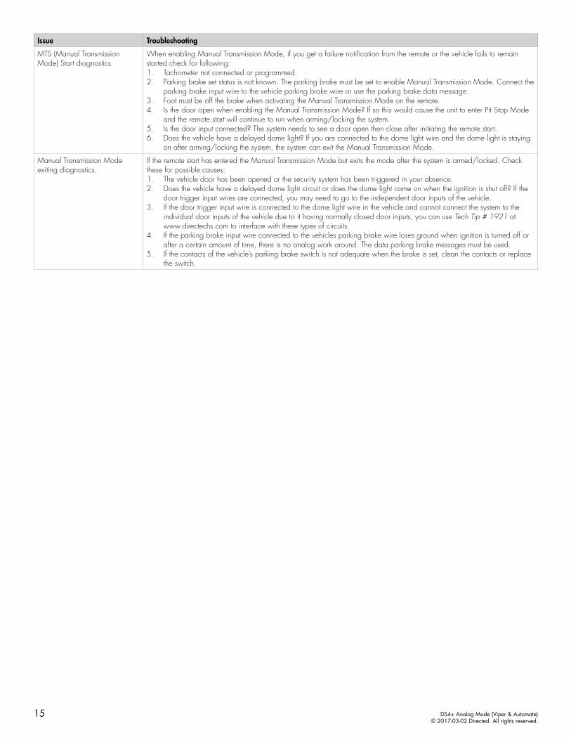
Issue Troubleshooting
MTS (Manual Transmission Mode) Start diagnostics.
When enabling Manual Transmission Mode, if you get a failure notification from the remote or the vehicle fails to remain started check for following:1. Tachometer not connected or programmed.2. Parking brake set status is not known. The parking brake must be set to enable Manual Transmission Mode. Connect the
parking brake input wire to the vehicle parking brake wire or use the parking brake data message.3. Foot must be off the brake when activating the Manual Transmission Mode on the remote.4. Is the door open when enabling the Manual Transmission Mode? If so this would cause the unit to enter Pit Stop Mode
and the remote start will continue to run when arming/locking the system.5. Is the door input connected? The system needs to see a door open then close after initiating the remote start.6. Does the vehicle have a delayed dome light? If you are connected to the dome light wire and the dome light is staying
on after arming/locking the system, the system can exit the Manual Transmission Mode.
Manual Transmission Mode exiting diagnostics.
If the remote start has entered the Manual Transmission Mode but exits the mode after the system is armed/locked. Check these for possible causes:1. The vehicle door has been opened or the security system has been triggered in your absence.2. Does the vehicle have a delayed dome light circuit or does the dome light come on when the ignition is shut off? If the
door trigger input wires are connected, you may need to go to the independent door inputs of the vehicle.3. If the door trigger input wire is connected to the dome light wire in the vehicle and cannot connect the system to the
individual door inputs of the vehicle due to it having normally closed door inputs, you can use Tech Tip # 1921 at www.directechs.com to interface with these types of circuits.
4. If the parking brake input wire connected to the vehicles parking brake wire loses ground when ignition is turned off or after a certain amount of time, there is no analog work around. The data parking brake messages must be used.
5. If the contacts of the vehicle’s parking brake switch is not adequate when the brake is set, clean the contacts or replace the switch.
16 DS4+ Analog Mode (Viper & Automate)© 2017-03-02 Directed. All rights reserved.
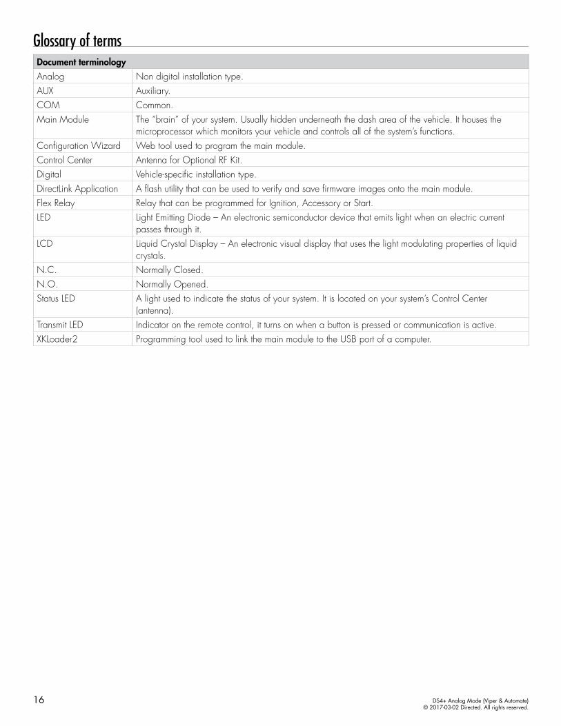
Glossary of termsDocument terminologyAnalog Non digital installation type.AUX Auxiliary.COM Common.Main Module The “brain” of your system. Usually hidden underneath the dash area of the vehicle. It houses the
microprocessor which monitors your vehicle and controls all of the system’s functions.Configuration Wizard Web tool used to program the main module.Control Center Antenna for Optional RF Kit.Digital Vehicle-specific installation type.DirectLink Application A flash utility that can be used to verify and save firmware images onto the main module.Flex Relay Relay that can be programmed for Ignition, Accessory or Start.LED Light Emitting Diode – An electronic semiconductor device that emits light when an electric current
passes through it.LCD Liquid Crystal Display – An electronic visual display that uses the light modulating properties of liquid
crystals.N.C. Normally Closed.N.O. Normally Opened.Status LED A light used to indicate the status of your system. It is located on your system’s Control Center
(antenna).Transmit LED Indicator on the remote control, it turns on when a button is pressed or communication is active.XKLoader2 Programming tool used to link the main module to the USB port of a computer.
17 DS4+ Analog Mode (Viper & Automate)© 2017-03-02 Directed. All rights reserved.
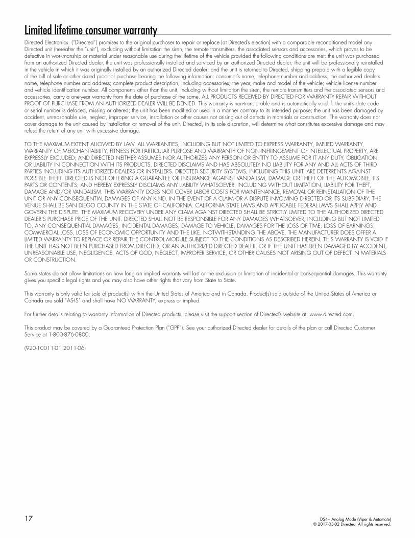
Limited lifetime consumer warrantyDirected Electronics. (“Directed”) promises to the original purchaser to repair or replace (at Directed’s election) with a comparable reconditioned model any Directed unit (hereafter the “unit”), excluding without limitation the siren, the remote transmitters, the associated sensors and accessories, which proves to be defective in workmanship or material under reasonable use during the lifetime of the vehicle provided the following conditions are met: the unit was purchased from an authorized Directed dealer, the unit was professionally installed and serviced by an authorized Directed dealer; the unit will be professionally reinstalled in the vehicle in which it was originally installed by an authorized Directed dealer; and the unit is returned to Directed, shipping prepaid with a legible copy of the bill of sale or other dated proof of purchase bearing the following information: consumer’s name, telephone number and address; the authorized dealers name, telephone number and address; complete product description, including accessories; the year, make and model of the vehicle; vehicle license number and vehicle identification number. All components other than the unit, including without limitation the siren, the remote transmitters and the associated sensors and accessories, carry a one-year warranty from the date of purchase of the same. ALL PRODUCTS RECEIVED BY DIRECTED FOR WARRANTY REPAIR WITHOUT PROOF OF PURCHASE FROM AN AUTHORIZED DEALER WILL BE DENIED. This warranty is non-transferable and is automatically void if: the unit’s date code or serial number is defaced, missing or altered; the unit has been modified or used in a manner contrary to its intended purpose; the unit has been damaged by accident, unreasonable use, neglect, improper service, installation or other causes not arising out of defects in materials or construction. The warranty does not cover damage to the unit caused by installation or removal of the unit. Directed, in its sole discretion, will determine what constitutes excessive damage and may refuse the return of any unit with excessive damage. TO THE MAXIMUM EXTENT ALLOWED BY LAW, ALL WARRANTIES, INCLUDING BUT NOT LIMITED TO EXPRESS WARRANTY, IMPLIED WARRANTY, WARRANTY OF MERCHANTABILITY, FITNESS FOR PARTICULAR PURPOSE AND WARRANTY OF NON-INFRINGEMENT OF INTELLECTUAL PROPERTY, ARE EXPRESSLY EXCLUDED; AND DIRECTED NEITHER ASSUMES NOR AUTHORIZES ANY PERSON OR ENTITY TO ASSUME FOR IT ANY DUTY, OBLIGATION OR LIABILITY IN CONNECTION WITH ITS PRODUCTS. DIRECTED DISCLAIMS AND HAS ABSOLUTELY NO LIABILITY FOR ANY AND ALL ACTS OF THIRD PARTIES INCLUDING ITS AUTHORIZED DEALERS OR INSTALLERS. DIRECTED SECURITY SYSTEMS, INCLUDING THIS UNIT, ARE DETERRENTS AGAINST POSSIBLE THEFT. DIRECTED IS NOT OFFERING A GUARANTEE OR INSURANCE AGAINST VANDALISM, DAMAGE OR THEFT OF THE AUTOMOBILE, ITS PARTS OR CONTENTS; AND HEREBY EXPRESSLY DISCLAIMS ANY LIABILITY WHATSOEVER, INCLUDING WITHOUT LIMITATION, LIABILITY FOR THEFT, DAMAGE AND/OR VANDALISM. THIS WARRANTY DOES NOT COVER LABOR COSTS FOR MAINTENANCE, REMOVAL OR REINSTALLATION OF THE UNIT OR ANY CONSEQUENTIAL DAMAGES OF ANY KIND. IN THE EVENT OF A CLAIM OR A DISPUTE INVOLVING DIRECTED OR ITS SUBSIDIARY, THE VENUE SHALL BE SAN DIEGO COUNTY IN THE STATE OF CALIFORNIA. CALIFORNIA STATE LAWS AND APPLICABLE FEDERAL LAWS SHALL APPLY AND GOVERN THE DISPUTE. THE MAXIMUM RECOVERY UNDER ANY CLAIM AGAINST DIRECTED SHALL BE STRICTLY LIMITED TO THE AUTHORIZED DIRECTED DEALER’S PURCHASE PRICE OF THE UNIT. DIRECTED SHALL NOT BE RESPONSIBLE FOR ANY DAMAGES WHATSOEVER, INCLUDING BUT NOT LIMITED TO, ANY CONSEQUENTIAL DAMAGES, INCIDENTAL DAMAGES, DAMAGE TO VEHICLE, DAMAGES FOR THE LOSS OF TIME, LOSS OF EARNINGS, COMMERCIAL LOSS, LOSS OF ECONOMIC OPPORTUNITY AND THE LIKE. NOTWITHSTANDING THE ABOVE, THE MANUFACTURER DOES OFFER A LIMITED WARRANTY TO REPLACE OR REPAIR THE CONTROL MODULE SUBJECT TO THE CONDITIONS AS DESCRIBED HEREIN. THIS WARRANTY IS VOID IF THE UNIT HAS NOT BEEN PURCHASED FROM DIRECTED, OR AN AUTHORIZED DIRECTED DEALER, OR IF THE UNIT HAS BEEN DAMAGED BY ACCIDENT, UNREASONABLE USE, NEGLIGENCE, ACTS OF GOD, NEGLECT, IMPROPER SERVICE, OR OTHER CAUSES NOT ARISING OUT OF DEFECT IN MATERIALS OR CONSTRUCTION.
Some states do not allow limitations on how long an implied warranty will last or the exclusion or limitation of incidental or consequential damages. This warranty gives you specific legal rights and you may also have other rights that vary from State to State.
This warranty is only valid for sale of product(s) within the United States of America and in Canada. Product(s) sold outside of the United States of America or Canada are sold “AS-IS” and shall have NO WARRANTY, express or implied.
For further details relating to warranty information of Directed products, please visit the support section of Directed’s website at: www.directed.com.
This product may be covered by a Guaranteed Protection Plan (“GPP”). See your authorized Directed dealer for details of the plan or call Directed Customer Service at 1-800-876-0800.
(920-10011-01 2011-06)
DS4+ Analog Mode (Viper & Automate)© 2017-03-02 Directed. All rights reserved.
Quick Reference Guide
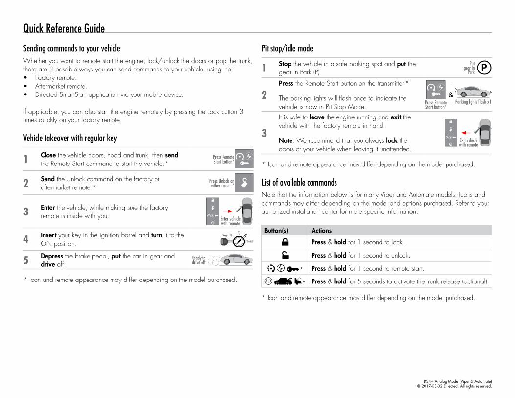
Pit stop/idle mode
1 Stop the vehicle in a safe parking spot and put the gear in Park (P).
Put gear in
Park
2Press the Remote Start button on the transmitter.*
The parking lights will flash once to indicate the vehicle is now in Pit Stop Mode.
Parking lights flash x1
14:36
Press Remote Start button*
&
3
It is safe to leave the engine running and exit the vehicle with the factory remote in hand.
Note: We recommend that you always lock the doors of your vehicle when leaving it unattended.
14:36Exit vehicle with remote
* Icon and remote appearance may differ depending on the model purchased.
List of available commandsNote that the information below is for many Viper and Automate models. Icons and commands may differ depending on the model and options purchased. Refer to your authorized installation center for more specific information.
Button(s) Actions
Press & hold for 1 second to lock.
Press & hold for 1 second to unlock.
* Press & hold for 1 second to remote start.
* Press & hold for 5 seconds to activate the trunk release (optional).
* Icon and remote appearance may differ depending on the model purchased.
Sending commands to your vehicleWhether you want to remote start the engine, lock/unlock the doors or pop the trunk, there are 3 possible ways you can send commands to your vehicle, using the:• Factory remote.• Aftermarket remote.• Directed SmartStart application via your mobile device.
If applicable, you can also start the engine remotely by pressing the Lock button 3 times quickly on your factory remote.
Vehicle takeover with regular key
1 Close the vehicle doors, hood and trunk, then send the Remote Start command to start the vehicle.* 14:36Press Remote
Start button*
2 Send the Unlock command on the factory or aftermarket remote.*
14:36Press Unlock on either remote*
3 Enter the vehicle, while making sure the factory remote is inside with you.
14:36Enter vehicle with remote
4 Insert your key in the ignition barrel and turn it to the ON position. START
Key OUT ONOFF
START
Key IN ONOFF
START
Key IN ONOFF
START
Key IN ONOFF
5 Depress the brake pedal, put the car in gear and drive off.
Ready to drive off
* Icon and remote appearance may differ depending on the model purchased.
DS4+ Analog Mode (Viper & Automate)© 2017-03-02 Directed. All rights reserved.
SmartStart compatibleThis system is equipped with a Bluetooth version of SmartStart offering up to 200' of range. The simple graphical interface gives you control over the following features of your installed remote start system or security with remote start system:• Lock/Arm• Unlock/Disarm• Remote Car Starter• Trunk Release• Panic• AUX Channels
You can also control multiple vehicles – great for families – and assign more than one user to control a vehicle. It’s easy with SmartStart! But, this is only the beginning! SmartStart is loaded with additional features including GPS tracking, SmartSchedule, vehicle status, roadside assistance, parked car finder and more.
The application enables a “Cloud-Connected Car” like never before, providing 2-way interaction with your vehicle. Connectivity is managed through the Directed Cloud Services (DCS) network linking car, app, end user, and the Internet.
For more information, visit www.mysmartstart.com.
Notes