
Analog Drive - Elektron
20
Multi-circuit Analog Distortion Unit User Manual Analog Drive
Transcript of Analog Drive - Elektron

Multi-circuit Analog Distortion Unit
User Manual
AnalogDrive


THANK YOUThank you for purchasing the Analog Drive. Congratulations! The Analog Drive gives you eight analog distortion types in one box. It is the ideal pedal for musicians who want to wreak havoc to signals and tones in the most diverse and characterful way possible.
This User Manual will guide you through the functions of the Analog Drive.
We wish you a happy analog experience. Have fun!
- The Elektron Team
Analog Drive

4
FCC compliance statementThis device complies with part 15 of the FCC rules. Operation is subject to the following two con-ditions: (1) This device may not cause harmful interference, and (2) this device must accept any interference received, including interference that may cause undesired operation.
NOTE: This equipment has been tested and found to comply with the limits for a Class B digital device, pursuant to Part 15 of the FCC Rules. These limits are designed to provide reasonable protection against harmful interference in a residential installation. This equipment generates, uses and can radiate radio frequency energy and, if not installed and used in accordance with the instructions, may cause harmful interference to radio communications. However, there is no guarantee that interference will not occur in a particular installation. If this equipment does cause harmful interference to radio or television reception, which can be determined by turning the equipment off and on, the user is encouraged to try to correct the interference by one or more of the following measures:
• Reorient or relocate the receiving antenna.• Increase the separation between the equipment and receiver.• Connect the equipment into an outlet on a circuit different from that to which the receiver is
connected.• Consult the dealer or an experienced radio/TV technician for help.
European Union regulation compliance statementThis product has been tested to comply with the Low Voltage Directive 2006/95/EC and the Electromagnetic Compatibility Directive 2004/108/EC. The product meets the requirements of RoHS 2 Directive 2011/65/EU.
This product must be disposed of properly according to local laws and regulations.

5
IMPORTANT SAFETY INSTRUCTIONS
1. Do not use the unit near water.2. Never use aggressive cleaners on the casing or the screen. Remove dust, dirt and fingerprints with
a soft, dry and non-abrasive cloth. More persistent dirt can be removed with a slightly damp cloth using only water. Disconnect all cables before doing this. Only reconnect them when the product is safely dry.
3. Install in accordance with the manufacturer’s instructions. Make sure you place the unit on a stable surface before use.
4. Connect the unit to an easily accessible electrical outlet close to the unit.5. When transporting the unit, preferably use accessories recommended by the manufacturer or the
box and padding the unit was originally shipped in.6. Do not install near any heat sources such as radiators, heat registers, stoves, or any other
appliance (including amplifiers) emitting heat.7. This product, in combination with an amplifier and speakers or headphones, is capable of producing
sound levels that can cause permanent hearing loss. Do not operate for a long period of time at a high volume level or at a level that is uncomfortable.
8. Protect the power cord from being walked on or pinched particularly at plugs, convenience receptacles, and the point where they exit from the unit.
9. Use attachments/accessories specified by the manufacturer.10. Unplug this unit during lightning storms or when it is not used for an extended time.11. Refer all servicing to qualified service technicians. Servicing is required when the unit has been
damaged in any way, a liquid has been spilled, or objects have fallen into the unit, the unit has been exposed to rain or moisture, does not operate normally, or has been dropped.

6
WARNING!
TO REDUCE THE RISK OF FIRE, ELECTRICAL SHOCK OR PRODUCT DAMAGE• Do not expose the unit to rain, moisture, dripping or splashing and also avoid placing objects filled
with liquid, such as vases, on the unit.• Do not expose the unit to direct sunlight, as this can lead to malfunction.• Do not open the casing. There are no user repairable or adjustable parts inside. Leave service and
repairs to trained service technicians only.• Do not exceed the limitations specified in the Electrical specifications.
SAFETY INSTRUCTIONS FOR THE POWER ADAPTER ELEKTRON PSU-3B• The adapter is not safety grounded and may only be used indoors.• To ensure good ventilation for the adapter, do not place it in tight spaces. To prevent a risk of elec-
tric shock and fire because of overheating, ensure that curtains and other objects do not prevent adapter ventilation.
• Do not expose the power adapter to direct sunlight, nor use it in ambient temperatures exceeding 40°C.
• Connect the adapter to an easily accessible electrical outlet close to the unit.• The adapter is in standby mode when the power cord is connected. The primary circuit is always
active as long as the cord is connected to the power outlet. Pull out the power cord to completely disconnect the adapter.
• In the EU, only use CE approved power cords.
ALLERGY WARNING• The rubber mat under the Analog Drive contains natural rubber latex. Please take precautions if you
have a latex sensitivity.
Legal disclaimerThe information in this document is subject to change without notice and should not be construed as a commitment by Elektron. Elektron assumes no responsibility for any errors that may appear in this document. Elektron may also make improvements and/or changes in the products and pro-grams described in this document at any time without notice. In no event shall Elektron be liable for any special, indirect, or consequential damages or any damages whatsoever resulting from loss of use, data, or profits, whether in an action of contract, negligence, or other action, arising out of or in connection with the use or performance of this information.

7

8
TABLE OF CONTENTS
1. INTRODUCTION. . . . . . . . . . . . . . . . . . . . . . . . . . . . . . . . . . . . . . . . . . . . . . . . . . . . . . . . . . . . . . . . . . . . . . . . . . . . . . . . . . . . . 91.1 CONVENTIONS IN THIS MANUAL . . . . . . . . . . . . . . . . . . . . . . . . . . . . . . . . . . . . . . . . . . . . . . . . . . . . . . . . . .9
2. PANEL LAYOUT AND CONNECTIONS . . . . . . . . . . . . . . . . . . . . . . . . . . . . . . . . . . . . . . . . . . . . . . . . . . . . . . . . . . . 102.1 FRONT PANEL CONTROLS . . . . . . . . . . . . . . . . . . . . . . . . . . . . . . . . . . . . . . . . . . . . . . . . . . . . . . . . . . . . . . . 102.2 REAR PANEL CONNECTIONS . . . . . . . . . . . . . . . . . . . . . . . . . . . . . . . . . . . . . . . . . . . . . . . . . . . . . . . . . . . . 11
3. CONNECTING THE ANALOG DRIVE . . . . . . . . . . . . . . . . . . . . . . . . . . . . . . . . . . . . . . . . . . . . . . . . . . . . . . . . . . . . . 12
4. SIGNAL FLOW . . . . . . . . . . . . . . . . . . . . . . . . . . . . . . . . . . . . . . . . . . . . . . . . . . . . . . . . . . . . . . . . . . . . . . . . . . . . . . . . . . . . . 124.1 AUDIO SIGNAL FLOW . . . . . . . . . . . . . . . . . . . . . . . . . . . . . . . . . . . . . . . . . . . . . . . . . . . . . . . . . . . . . . . . . . . . 12
5. USER INTERFACE . . . . . . . . . . . . . . . . . . . . . . . . . . . . . . . . . . . . . . . . . . . . . . . . . . . . . . . . . . . . . . . . . . . . . . . . . . . . . . . . . 125.1 PRESETS . . . . . . . . . . . . . . . . . . . . . . . . . . . . . . . . . . . . . . . . . . . . . . . . . . . . . . . . . . . . . . . . . . . . . . . . . . . . . . . . 125.2 ACTIVE . . . . . . . . . . . . . . . . . . . . . . . . . . . . . . . . . . . . . . . . . . . . . . . . . . . . . . . . . . . . . . . . . . . . . . . . . . . . . . . . . . 135.3 MANUAL MODE. . . . . . . . . . . . . . . . . . . . . . . . . . . . . . . . . . . . . . . . . . . . . . . . . . . . . . . . . . . . . . . . . . . . . . . . . . 145.4 EFFECT CIRCUITS . . . . . . . . . . . . . . . . . . . . . . . . . . . . . . . . . . . . . . . . . . . . . . . . . . . . . . . . . . . . . . . . . . . . . . . 145.5 GAIN . . . . . . . . . . . . . . . . . . . . . . . . . . . . . . . . . . . . . . . . . . . . . . . . . . . . . . . . . . . . . . . . . . . . . . . . . . . . . . . . . . . . 145.6 EQ . . . . . . . . . . . . . . . . . . . . . . . . . . . . . . . . . . . . . . . . . . . . . . . . . . . . . . . . . . . . . . . . . . . . . . . . . . . . . . . . . . . . . . 145.7 LEVEL . . . . . . . . . . . . . . . . . . . . . . . . . . . . . . . . . . . . . . . . . . . . . . . . . . . . . . . . . . . . . . . . . . . . . . . . . . . . . . . . . . . 155.8 EXPRESSION PEDAL/CV INPUT . . . . . . . . . . . . . . . . . . . . . . . . . . . . . . . . . . . . . . . . . . . . . . . . . . . . . . . . . . 15
6. SETTINGS. . . . . . . . . . . . . . . . . . . . . . . . . . . . . . . . . . . . . . . . . . . . . . . . . . . . . . . . . . . . . . . . . . . . . . . . . . . . . . . . . . . . . . . . . . 156.1 CHANGING THE SETTINGS. . . . . . . . . . . . . . . . . . . . . . . . . . . . . . . . . . . . . . . . . . . . . . . . . . . . . . . . . . . . . . . 156.2 SETTINGS . . . . . . . . . . . . . . . . . . . . . . . . . . . . . . . . . . . . . . . . . . . . . . . . . . . . . . . . . . . . . . . . . . . . . . . . . . . . . . . 156.3 OS UPGRADE. . . . . . . . . . . . . . . . . . . . . . . . . . . . . . . . . . . . . . . . . . . . . . . . . . . . . . . . . . . . . . . . . . . . . . . . . . . . 176.4 FACTORY RESET . . . . . . . . . . . . . . . . . . . . . . . . . . . . . . . . . . . . . . . . . . . . . . . . . . . . . . . . . . . . . . . . . . . . . . . . 17
7. TECHNICAL INFORMATION. . . . . . . . . . . . . . . . . . . . . . . . . . . . . . . . . . . . . . . . . . . . . . . . . . . . . . . . . . . . . . . . . . . . . . . 18
8. CREDITS AND CONTACT INFORMATION . . . . . . . . . . . . . . . . . . . . . . . . . . . . . . . . . . . . . . . . . . . . . . . . . . . . . . . 18
APPENDIX A: MIDI . . . . . . . . . . . . . . . . . . . . . . . . . . . . . . . . . . . . . . . . . . . . . . . . . . . . . . . . . . . . . . . . . . . . . . . . . . . . . . . . . . . 19

9
1. INTRODUCTION
1.1 CONVENTIONS IN THIS MANUALWe have used the following conventions throughout the manual:
Footswitch names are written in upper case, bold style and within brackets. For instance, the footswitch labeled “Bypass/Select” on the main panel is written as [FOOTSWITCH BYPASS/SELECT].
Knobs are written in upper case, bold, italic letters. For instance, the knob “Gain” is called GAIN.
LED indicators like the Active LED are written like this: <ACTIVE>.
Menu names are written in upper case letters. The SY menu is an example of that.
Bold, upper case letters are used for parameter setting alternatives, for example AL.
Analog Drive User Manual. This manual is copyright © 2016 Elektron Music Machines MAV AB. All reproduction with-out written authorization is strictly prohibited. The information in this manual may change without notice. Elektron’s product names, logotypes, titles, words or phrases may be registered and protected by Swedish and international law. All other brand or product names are trademarks or registered trademarks of their respective holders. This manual was last updated December 13, 2016.

10
2. PANEL LAYOUT AND CONNECTIONS
2.1 FRONT PANEL CONTROLS
Manual
Focused DistBig Dist
Dirty Drive
Mid Drive
Clean Boost
Harmonic Fuzz
High Gain
Thick GainGain Level
HighMidActiveMid FreqLow
Preset
Out In
Analog DriveMulti-circuit analog distortion unit
Bypass / Select
1 2 3 4 5
7
815
10121314
9
11
6
1. GAIN sets the level of the incoming signal that is sent to the effect circuit.2. CIRCUIT SELECTOR chooses between the eight different types of effect circuits.3. MANUAL sets the sound to match the state of the controls on the front panel and disables the
preset functionality.4. Display.5. PRESET selects from the stored sound presets.6. <PRESET INDICATORS> indicate which way the knob should be turned to locate the position cor-
responding to the value set in the preset.

11
7. LEVEL sets the pedal’s overall output level.8. HIGH adjusts the amount of boost or cut of the EQ (equalizer) high frequencies.9. [FOOTSWITCH RIGHT]10. MID adjusts the amount of boost or cut of the EQ mid frequencies.11. <ACTIVE> indicates if the pedal is active or bypassed.12. [FOOTSWITCH BYPASS/SELECT]13. MID FREQ adjusts the parametric EQ mid frequency.14. [FOOTSWITCH LEFT]15. LOW adjusts the amount of boost or cut of the EQ low frequencies.
2.2 REAR PANEL CONNECTIONS
Input Output Exp Gain Exp Mid MIDI In MIDI Out
12 VDC 1 A
1 2 3 4 5 6 7
8
1. Input. Audio input. Use 1/4” mono phone plug.2. Output. Audio output. Use 1/4” mono phone plug.3. Exp Gain. Input for expression pedal or CV to adjust the input signal gain. Use 1/4” mono phone
plug for CV signals.4. Exp Mid. Input for expression pedal or CV to adjust the MID FREQ. Use 1/4” mono phone plug for
CV signals.5. MIDI In. MIDI data input. Use standard MIDI cable to connect to MIDI Out of an external MIDI unit.6. MIDI Out. (Also functions as MIDI Thru) MIDI data output. Use standard MIDI cable to connect to
MIDI In of an external MIDI unit.7. Kensington Security Slot. For connecting a Kensington lock and cable.8. Power inlet. Use the included PSU-3b power adapter, connected to a power outlet.
12
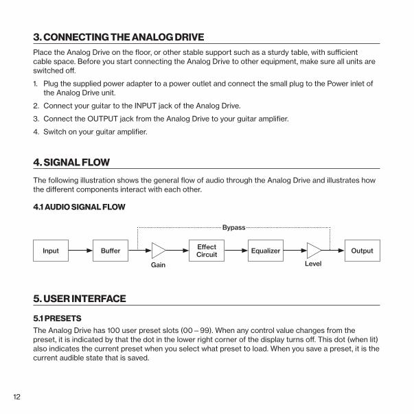
3. CONNECTING THE ANALOG DRIVEPlace the Analog Drive on the floor, or other stable support such as a sturdy table, with sufficient cable space. Before you start connecting the Analog Drive to other equipment, make sure all units are switched off.
1. Plug the supplied power adapter to a power outlet and connect the small plug to the Power inlet of the Analog Drive unit.
2. Connect your guitar to the INPUT jack of the Analog Drive.
3. Connect the OUTPUT jack from the Analog Drive to your guitar amplifier.
4. Switch on your guitar amplifier.
4. SIGNAL FLOW
The following illustration shows the general flow of audio through the Analog Drive and illustrates how the different components interact with each other.
4.1 AUDIO SIGNAL FLOW
Input Buffer
Level
OutputEffect Circuit
Gain
Equalizer
Bypass
5. USER INTERFACE
5.1 PRESETSThe Analog Drive has 100 user preset slots (00—99). When any control value changes from the preset, it is indicated by that the dot in the lower right corner of the display turns off. This dot (when lit) also indicates the current preset when you select what preset to load. When you save a preset, it is the current audible state that is saved.

13
LOADING A PRESETMethod 1
1. Turn PRESET to select the desired preset. The display blinks to indicate that the preset is not yet loaded.
2. Press PRESET to load the selected preset.
Method 2
1. Press [FOOTSWITCH LEFT] (decrease) or [FOOTSWITCH RIGHT] (increase) to select the desired preset. The slot decrement/increment can be done in steps of 10 by holding down either footswitch. The display blinks to indicate that the preset is not yet loaded.
2. Press [FOOTSWITCH BYPASS/SELECT] to load preset.
N.B. If you wait for more than 30 seconds to load the new preset, the display stops blinking and returns to the active preset’s number.
SAVING A PRESET1. Press and hold PRESET for 2 seconds. The display first shows SA and then blinks to indicate that
the preset is not yet saved.2. Turn PRESET and select the preset slot to where you want to save the current sound settings.3. Press PRESET to save.
N.B. If you wait for more than 5 seconds to save the preset, the display stops blinking and returns to the active preset’s number.
PRESET INDICATORSWhen a preset is selected, the recalled values of the parameters might not be the same as the knobs current physical position. As soon as a knob is turned, one of the <PRESET INDICATOR> LEDs indi-cates which way the knob should be turned to locate the position corresponding to the value set in the preset. When the knob is in the position that matches the stored value, both LEDs are lit for a short while and then turn off.
N.B. Turning a knob does not change the parameter value until the knob position matches the preset’s stored value.
5.2 ACTIVEThe Analog Drive must be active to affect the incoming sound. If the pedal is not active, then the effect is bypassed. Press [FOOTSWITCH BYPASS/SELECT] to toggle active on and off. The <ACTIVE> LED indicates if the effect is active or not.
14
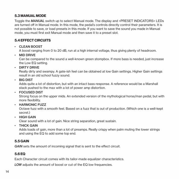
5.3 MANUAL MODEToggle the MANUAL switch up to select Manual mode. The display and <PRESET INDICATORS> LEDs are turned off in Manual mode. In this mode, the pedal’s controls directly control their parameters. It is not possible to save, or load presets in this mode. If you want to save the sound you made in Manual mode, you must first exit Manual mode and then save it to a preset slot.
5.4 EFFECT CIRCUITS
• CLEAN BOOST A boost ranging from 0 to 20 dB, run at a high internal voltage, thus giving plenty of headroom.
• MID DRIVE Can be compared to the sound a well-known green stompbox. If more bass is needed, just increase the Low EQ setting.
• DIRTY DRIVE Really dirty and swampy. A gate-ish feel can be obtained at low Gain settings. Higher Gain settings result in an old school fuzzy sound.
• BIG DIST Adds quite a lot of distortion, but with an intact bass response. A reference would be a Marshall stack pushed to the max with a lot of power amp distortion.
• FOCUSED DIST Strong focus on the upper mids. An extended version of the mythological horse/man pedal, but with more flexibility.
• HARMONIC FUZZ Octave fuzz with a smooth feel. Based on a fuzz that is out of production. (Which one is a well-kept secret.)
• HIGH GAIN Clear sound with a lot of gain. Nice string separation, great sustain.
• THICK GAIN Adds loads of gain, more than a lot of preamps. Really crispy when palm muting the lower strings and using the EQ to add some top end.
5.5 GAINGAIN sets the amount of incoming signal that is sent to the effect circuit.
5.6 EQEach Character circuit comes with its tailor-made equalizer characteristics.
LOW adjusts the amount of boost or cut of the EQ low frequencies.

15
MID FREQ adjusts the parametric EQ mid frequency. MID adjusts the amount of boost or cut of the EQ mid frequencies. HIGH adjusts the amount of boost or cut of the EQ high frequencies.
5.7 LEVELLEVEL sets the pedal’s final output level.
5.8 EXPRESSION PEDAL/CV INPUTThere are two jacks for connecting an expression pedal or Control Voltage signal source. The Exp Gain input adds more gain to the value of the preset/panel. The Exp Mid control input goes through the entire frequency range.
6. SETTINGSThe Analog Drive has a number of settings that can customize the functions of the pedal. These set-tings are stored globally and are not part of the preset.
6.1 CHANGING THE SETTINGS1. Press and hold [FOOTSWITCH LEFT] and [FOOTSWITCH RIGHT] for 2 seconds to enter the Set-
up mode. The display briefly shows SU to indicate that you are in Setup Mode. The current setting is also briefly shown in the display for a second and is also indicated by two or three Circuit LEDs. The display then changes to show the chosen value of the setting.
2. Turn CIRCUIT SELECTOR to select setting.3. Turn PRESET to change the value of the setting.4. Press and hold [FOOTSWITCH BYPASS/SELECT] to save the settings and exit the Setup mode.
Press and hold [FOOTSWITCH LEFT] and [FOOTSWITCH RIGHT] for 2 seconds to exit the Setup mode without saving any changes.
6.2 SETTINGSThese are the settings and setting values of the Analog Drive.
Setting Display Description
Input Channel Sets the MIDI channel that Analog Drive uses to receive MIDI data. No MIDI data is received when set to OF (OFF). (Range 1—16, OF)

16
Setting Display Description
Output Channel Sets the MIDI channel that Analog Drive uses to send MIDI data. No MIDI data is sent when set to OF (OFF). (Range 1—16, OF)
Output Thru Sets the behavior of the MIDI OUT port. OF = Off. Only sends data from the pedal. ON = On. Forwards data from MIDI IN. MM = Midi Merge. Merges and sends the data both from the MIDI IN port and from the pedal.
Expression Mid Sets the Exp Mid jack to receive CV or Expression pedal signals. E = Expression CU = CV To calibrate the range of the expression pedal: Connect the expres-sion pedal to Exp Mid. Press PRESET and move the expression pedal to max and then to min position.
Expression Gain Sets the Exp Gain jack to receive CV or Expression pedal signals. E = Expression CU = CV To calibrate the range of the expression pedal: Connect the expres-sion pedal to Exp Gain. Press PRESET and move the expression pedal to max and then to min position.
Expression Destination
Sets the destination of the signal from Exp Gain and Exp Mid. IE = Internal and External (MIDI) –E = Only External (MIDI) I– = Only Internal – – = No destination
Preset Destination Sets the destination of the PRESET knob (Program change). IE = Internal and External (MIDI) I– = only Internal
Continuous con-trollers Destination
Sets the destination of the continuous controllers (knobs). IE = Internal and External (MIDI) –E = Only External (MIDI) I– = Only Internal – – = No destination

17
6.3 OS UPGRADEYou also have the possibility to update the Analog Drive’s operating system using the MIDI In port. To send the OS SysEx file, use our free SysEx utility software C6, available for Windows and Mac OS (or other compatible SysEx software). You can download the OS SysEx file and the C6 software from the Elektron website.
1. Connect the device that you want to use to send the OS SysEx file to the MIDI In of the Analog Drive.2. Press and hold the PRESET knob and turn Analog Drive on by plugging in the power adapter to the
Power inlet. The display shows UP.3. Send the OS SysEx file, and then wait until the display shows AA or UE (see below).4. Restart the Analog Drive to return to normal use.
The display shows AA if the upgrade is successful. If the display shows UE, the upgrade failed, and you MUST repeat the OS upgrade process before you can use the Analog Drive again.
6.4 FACTORY RESETYou can reset the Analog Drive to the state it was when it left the factory with all its settings and pre-sets reverted to its original state.
1. Press and hold [FOOTSWITCH LEFT] and [FOOTSWITCH RIGHT], and then turn the Analog Drive on by plugging in the power adapter to the Power inlet. The display first shows FR, then YN.
2. Turn the PRESET knob so that Y starts blinking, and then press PRESET to initiate the factory reset.
Setting Display Description
SysEx SysEx send and receive utility.N.B. This is a function, not a setting that can be saved.
Sending SysEx AL = Send all presets. 00—99 = Send only the chosen preset. Press PRESET to initiate sending SysEx data
Receiving SysEx AL = Receive all sent presets in its original preset positions 00—99 = Receive all sent presets starting at the chosen preset position and then filling the preset slots upwards. After it reaches slot 99, it goes on to 00.
18
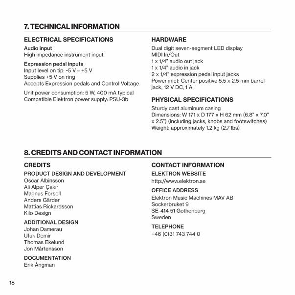
ELECTRICAL SPECIFICATIONSAudio input High impedance instrument input
Expression pedal inputs Input level on tip: -5 V – +5 V Supplies +5 V on ring Accepts Expression pedals and Control Voltage
Unit power consumption: 5 W, 400 mA typical Compatible Elektron power supply: PSU-3b
HARDWAREDual digit seven-segment LED display MIDI In/Out 1 x 1/4” audio out jack 1 x 1/4” audio in jack 2 x 1/4” expression pedal input jacks Power inlet: Center positive 5.5 x 2.5 mm barrel jack, 12 V DC, 1 A
PHYSICAL SPECIFICATIONSSturdy cast aluminum casing Dimensions: W 171 x D 177 x H 62 mm (6.8” x 7.0” x 2.5”) (including jacks, knobs and footswitches) Weight: approximately 1.2 kg (2.7 lbs)
7. TECHNICAL INFORMATION
8. CREDITS AND CONTACT INFORMATION
CREDITSPRODUCT DESIGN AND DEVELOPMENTOscar Albinsson Ali Alper Çakır Magnus Forsell Anders Gärder Mattias Rickardsson Kilo Design
ADDITIONAL DESIGNJohan Damerau Ufuk Demir Thomas Ekelund Jon Mårtensson
DOCUMENTATION Erik Ångman
CONTACT INFORMATIONELEKTRON WEBSITEhttp://www.elektron.se
OFFICE ADDRESSElektron Music Machines MAV AB Sockerbruket 9 SE-414 51 Gothenburg Sweden
TELEPHONE+46 (0)31 743 744 0

19
APPENDIX A: MIDI This appendix lists the MIDI specifications for the Analog Drive.
• Program change: 0—99.
• CV-mode: 10 bits, 7 in MSB, 3 in LSB. MSB=64 equals 0 V.
• Expression pedal mode: 9 bits. 7 in MSB, 2 in LSB.
• MIDI CC: 8 bits. 7 in MSB, 1 in LSB.
MIDI CCParameter CC MSB CC LSB Values
Gain 16 48
Low 17 49
Mid Freq 18 50
Mid 19 51
High 20 52
Level 21 53
Expression Gain 4 36
Expression Mid 1 33
Circuit Select 3 0—15 = Clean Boost 16—31 = Mid Drive 32—47 = Dirty Drive 48—63 = Big Dist 64—79 = Focused Dist 80—95 = Harmonic Fuzz 96—111 = High Gain 112—127 = Thick Gain
Effect Active 80 1—63 = Off 64—127 = On

851
2EN
G-C