
Analog 4 Manual OS1.21 Web
124
-
Upload
lasseeinar -
Category
Documents
-
view
213 -
download
1
description
Analog 4 Manual OS1.21 Web
Transcript of Analog 4 Manual OS1.21 Web
FCC compliance statementThis device complies with part 15 of the FCC rules. Operation is subject to the following two conditions: (1) This device may not cause harmful interference, and (2) this device must accept any interference received, including interference that may cause undesired operation.
NOTE: This equipment has been tested and found to comply with the limits for a Class B digital device, pursuant to Part 15 of the FCC Rules. These limits are designed to provide reasonable protection against harmful interference in a residential installation. This equipment generates, uses and can radiate radio frequency energy and, if not installed and used in accordance with the instructions, may cause harmful interference to radio communications. However, there is no guarantee that interference will not occur in a particular installation. If this equipment does cause harmful interference to radio or television reception, which can be determined by turning the equipment off and on, the user is encouraged to try to correct the interference by one or more of the following measures:
• Reorient or relocate the receiving antenna.• Increase the separation between the equipment and receiver.• Connect the equipment into an outlet on a circuit different from that to which the receiver is connected.• Consult the dealer or an experienced radio/TV technician for help.
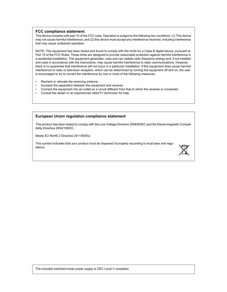
European Union regulation compliance statement
This product has been tested to comply with the Low Voltage Directive 2006/95/EC and the Electromagnetic Compat-ibility Directive 2004/108/EC.
Meets EU RoHS 2 Directive 2011/65/EU.
This symbol indicates that your product must be disposed of properly according to local laws and regu-lations.
The included switched-mode power supply is CEC Level V compliant.
WARNINGTo reduce the risk of fire, electrical shock or product damage:
• Do not expose the apparatus to rain, moisture, dripping or splashing and also avoid placing objects filled with liquid, such as vases, on the apparatus.
• Do not expose the apparatus to direct sunlight, nor use it in ambient temperatures exceeding 35°C.• Do not unmount the enclosure. There are no user repairable or adjustable parts inside. Leave service and repairs to trained service
personnel only.
ADDITIONAL INSTRUCTIONS FOR THE POWER ADAPTER ELEKTRON PSU-3
WARNING
• The adapter is not safety grounded and may only be used indoors.
• To ensure good ventilation for the adapter, do not place it in tight spaces. To prevent risk of electric shock and fire because of over-heating, ensure that curtains and other objects do not prevent adapter ventilation.
• Do not expose the power adapter to direct sunlight, nor use it in ambient temperatures exceeding 40°C.
• Connect the adapter to an easily accessible electrical outlet close to the apparatus.
The adapter is in standby mode when the power cord is connected, the primary circuit is always active as long as the cord is con-nected to the power outlet. Pull out the power cord to completely disconnect the adapter.
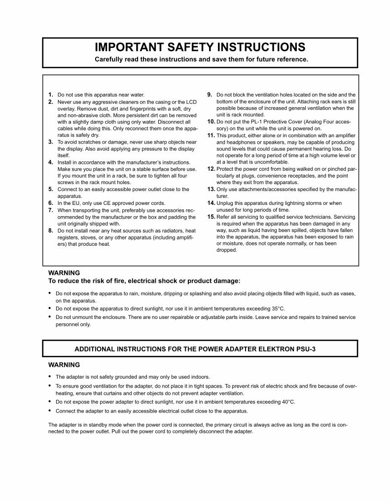
IMPORTANT SAFETY INSTRUCTIONSCarefully read these instructions and save them for future reference.
1. Do not use this apparatus near water.2. Never use any aggressive cleaners on the casing or the LCD
overlay. Remove dust, dirt and fingerprints with a soft, dry and non-abrasive cloth. More persistent dirt can be removed with a slightly damp cloth using only water. Disconnect all cables while doing this. Only reconnect them once the appa-ratus is safely dry.
3. To avoid scratches or damage, never use sharp objects near the display. Also avoid applying any pressure to the display itself.
4. Install in accordance with the manufacturer’s instructions. Make sure you place the unit on a stable surface before use. If you mount the unit in a rack, be sure to tighten all four screws in the rack mount holes.
5. Connect to an easily accessible power outlet close to the apparatus.
6. In the EU, only use CE approved power cords.7. When transporting the unit, preferably use accessories rec-
ommended by the manufacturer or the box and padding the unit originally shipped with.
8. Do not install near any heat sources such as radiators, heat registers, stoves, or any other apparatus (including amplifi-ers) that produce heat.
9. Do not block the ventilation holes located on the side and the bottom of the enclosure of the unit. Attaching rack ears is still possible because of increased general ventilation when the unit is rack mounted.
10. Do not put the PL-1 Protective Cover (Analog Four acces-sory) on the unit while the unit is powered on.
11. This product, either alone or in combination with an amplifier and headphones or speakers, may be capable of producing sound levels that could cause permanent hearing loss. Do not operate for a long period of time at a high volume level or at a level that is uncomfortable.
12. Protect the power cord from being walked on or pinched par-ticularly at plugs, convenience receptacles, and the point where they exit from the apparatus.
13. Only use attachments/accessories specified by the manufac-turer.
14. Unplug this apparatus during lightning storms or when unused for long periods of time.
15. Refer all servicing to qualified service technicians. Servicing is required when the apparatus has been damaged in any way, such as liquid having been spilled, objects have fallen into the apparatus, the apparatus has been exposed to rain or moisture, does not operate normally, or has been dropped.


1 of 4
INTRODUCTION.............................................................................................................1CONVENTIONS IN THIS MANUAL........................................................................................................ 1
THE BACKGROUND OF THE ANALOG FOUR.............................................................2PANEL LAYOUT AND CONNECTORS...........................................................................3
FRONT PANEL....................................................................................................................................... 3REAR CONNECTORS ........................................................................................................................... 4ANALOG FOUR ACCESSORIES........................................................................................................... 5
RACK MOUNT KIT ............................................................................................................................ 5ECC-2 CARRYING BAG & PL-2 PROTECTIVE LID......................................................................... 5
CONNECTING THE UNIT ...................................................................................................................... 5
ANALOG FOUR SIGNAL PATH......................................................................................6ABOUT THE COMPONENTS................................................................................................................. 6
COMMENTS ON THE SIGNAL PATH............................................................................................... 6ABOUT THE OSCILLATORS AND FILTERS .................................................................................... 6
OVERVIEW OF THE ANALOG FOUR STRUCTURE.....................................................7+DRIVE................................................................................................................................................... 7DATA STRUCTURE................................................................................................................................ 7
PROJECT.......................................................................................................................................... 7KIT ..................................................................................................................................................... 7SOUND.............................................................................................................................................. 8BANK................................................................................................................................................. 8PATTERN........................................................................................................................................... 8SONG ................................................................................................................................................ 8CHAINS ............................................................................................................................................. 8GLOBAL ............................................................................................................................................ 8
ABOUT THE TRACK TYPES ................................................................................................................. 8THE SYNTH TRACKS....................................................................................................................... 8THE FX TRACK................................................................................................................................. 8THE CV TRACK ................................................................................................................................ 8EDITING THE TRACKS .................................................................................................................... 8
THE USER INTERFACE..................................................................................................9PARAMETER EDITING .......................................................................................................................... 9
QUICK PARAMETER EDITING......................................................................................................... 9PARAMETER VALUE JUMP ............................................................................................................. 9
QUICK SCROLLING............................................................................................................................. 10COPY, CLEAR AND PASTE ................................................................................................................. 10THE NAMING MENU............................................................................................................................ 10
POP-UP MENU NAMING ................................................................................................................ 10OVERBRIDGE.......................................................................................................................................11
QUICK START ...............................................................................................................12PLAYING THE FACTORY PRESETS................................................................................................... 12
PERFORMANCE MODE ................................................................................................................. 12ADJUSTING PARAMETERS........................................................................................................... 12
PROJECTS ....................................................................................................................13PROJECT MENU ................................................................................................................................. 13
KITS AND SOUNDS ......................................................................................................15THE +DRIVE SOUND LIBRARY AND THE SOUND POOL ................................................................ 15KIT MENU............................................................................................................................................. 16PERFORMANCE MODE ...................................................................................................................... 16
PERFORMANCE SETUP................................................................................................................ 17

2 of 4
PERFORMANCE MUTE.................................................................................................................. 18PERFORMANCE MIXER................................................................................................................. 18
POLYPHONY........................................................................................................................................ 19POLYPHONY CONFIGURATION.................................................................................................... 19
VOICE ROUTING ................................................................................................................................. 20SOUND MENU ..................................................................................................................................... 23PLAYING A SOUND ............................................................................................................................. 27
PLAYING A SOUND WITH A MIDI KEYBOARD ............................................................................. 27EDITING A SOUND .............................................................................................................................. 27EDITING THE FX AND CV TRACKS ................................................................................................... 28
THE FX TRACK............................................................................................................................... 28THE CV TRACK............................................................................................................................... 28
TRACK MUTING................................................................................................................................... 28
THE SEQUENCER ........................................................................................................ 29BASIC PATTERN OPERATIONS.......................................................................................................... 29
SELECTING A PATTERN................................................................................................................ 29PATTERN CONTROL ...................................................................................................................... 29TEMPO ............................................................................................................................................ 30
PATTERN MODES................................................................................................................................ 30EDITING APATTERN............................................................................................................................ 30
TRIG TYPES.................................................................................................................................... 31GRID RECORDING MODE ............................................................................................................. 31LIVE RECORDING MODE .............................................................................................................. 31
TRACK MENU ...................................................................................................................................... 32PATTERN MENU .................................................................................................................................. 32ARPEGGIATOR.................................................................................................................................... 33
ARPEGGIATOR SETUP.................................................................................................................. 34NOTE MENU ........................................................................................................................................ 34
NOTES SETUP................................................................................................................................ 35CLICK TRACK ...................................................................................................................................... 36SCALE MENU....................................................................................................................................... 36
NORMAL MODE.............................................................................................................................. 36ADVANCED MODE ......................................................................................................................... 37
SEQUENCER FEATURES ................................................................................................................... 38PARAMETER LOCKS...................................................................................................................... 38SOUND LOCKS............................................................................................................................... 38TRIG MUTE ..................................................................................................................................... 38ACCENT .......................................................................................................................................... 39NOTE SLIDE.................................................................................................................................... 39PARAMETER SLIDE ....................................................................................................................... 40SWING............................................................................................................................................. 40TRACK TRANSPOSE...................................................................................................................... 40DESTRUCTIVE TRANSPOSE ........................................................................................................ 41COPY, PASTE AND CLEAR OPERATIONS.................................................................................... 41QUICK SAVE AND RELOAD COMMANDS .................................................................................... 41
.............................................................................................................................................................. 42
CHAINS AND SONGS................................................................................................... 43CHAINS ................................................................................................................................................ 43SONGS ................................................................................................................................................. 44
SONG EDIT MENU.......................................................................................................................... 44ADDING SONG ROWS AND ASSIGNING PATTERNS AND CHAINS........................................... 44ADDING REPEATS, MUTES AND TRANSPOSE INFORMATION ................................................. 45SONG MENU................................................................................................................................... 45

3 of 4
GLOBAL MENU.............................................................................................................46PROJECT ............................................................................................................................................. 46GLOBAL SLOT ..................................................................................................................................... 46SYNTH MASTER TUNE....................................................................................................................... 46SEQUENCER CONFIG ........................................................................................................................ 47MIDI CONFIG ....................................................................................................................................... 47
MIDI SYNC ...................................................................................................................................... 47MIDI PORT CONFIG ....................................................................................................................... 48MIDI CHANNELS............................................................................................................................. 49MULTI MAP EDIT ............................................................................................................................ 50
CV CONFIG.......................................................................................................................................... 53CV A-D CONFIG.............................................................................................................................. 53VOLTAGE TRIM............................................................................................................................... 55
VOICE ROUTING ................................................................................................................................. 55SYSEX DUMP ...................................................................................................................................... 56
SYSEX SEND.................................................................................................................................. 56SYSEX RECEIVE............................................................................................................................ 57
SYSTEM ............................................................................................................................................... 58USB CONFIG .................................................................................................................................. 58OS UPGRADE................................................................................................................................. 58FORMAT +DRIVE............................................................................................................................ 59CALIBRATION ................................................................................................................................. 59
EARLY STARTUP MENU ..............................................................................................60TEST MODE......................................................................................................................................... 60EMPTY RESET .................................................................................................................................... 60FACTORY RESET ................................................................................................................................ 60OS UPGRADE...................................................................................................................................... 60
MORE ON OSCILLATORS, FILTERS AND ENVELOPES ...........................................61OSCILLATORS ..................................................................................................................................... 61
OTHER OSCILLATOR WAVEFORM SELECTIONS ....................................................................... 62FILTERS ............................................................................................................................................... 63
4-POLE LADDER FILTER ............................................................................................................... 632-POLE MULTI MODE FILTER........................................................................................................ 63
ENVELOPES ........................................................................................................................................ 64
SETUP EXAMPLES.......................................................................................................65ANALOG FOUR CONTROL OF AN EXTERNAL ANALOG SYNTHESIZER....................................... 65ANALOG FOUR WITH OTHER ELEKTRON GEAR ............................................................................ 67ANALOG FOUR AS A FILTER BANK................................................................................................... 68USING AN EXTERNAL OSCILLATOR WITH THE ANALOG FOUR ................................................... 70ANALOG FOUR WITH AN ELECTRIC GUITAR .................................................................................. 72
TECHNICAL INFORMATION.........................................................................................74SPECIFICATIONS ................................................................................................................................ 74
CREDITS AND CONTACT INFORMATION ..................................................................75CREDITS .............................................................................................................................................. 75
PRODUCT DESIGN AND DEVELOPMENT ................................................................................... 75ADDITIONAL DESIGN .................................................................................................................... 75FACTORY DEFAULT SOUND DESIGN .......................................................................................... 75REFERENCE MANUAL................................................................................................................... 75
CONTACT INFORMATION................................................................................................................... 75ELEKTRON WEBSITE .................................................................................................................... 75DELIVERY ADDRESS..................................................................................................................... 75

4 of 4
TELEPHONE ................................................................................................................................... 75
APPENDIX A: SYNTH TRACK PARAMETERSOSCILLATOR 1....................................................................................................................................... 1OSCILLATOR 2....................................................................................................................................... 2FILTERS.................................................................................................................................................. 3AMPLITUDE ........................................................................................................................................... 4ENVELOPES .......................................................................................................................................... 5LFO ......................................................................................................................................................... 6
APPENDIX B: FX TRACK PARAMETERSEXTERNAL IN ........................................................................................................................................ 1WIDESHIFT CHORUS............................................................................................................................ 2SATURATOR DELAY.............................................................................................................................. 3SUPERVOID REVERB ........................................................................................................................... 4FX LFO ................................................................................................................................................... 5
APPENDIX C: CV TRACK PARAMETERSCV A-D.................................................................................................................................................... 1CV ENVELOPES .................................................................................................................................... 5CV LFO ................................................................................................................................................... 6
APPENDIX D: MIDIPERFORMANCE PARAMETERS........................................................................................................... 1MODULATION PARAMETERS............................................................................................................... 1SYNTH TRACK PARAMETERS ............................................................................................................. 2FX TRACK PARAMETERS..................................................................................................................... 9CV TRACK PARAMETERS .................................................................................................................. 11
APPENDIX E: ANALOG FOUR ARCHITECTUREINDEX

INTRODUCTION
1
INTRODUCTIONThank you for choosing the Analog Four. It is a digitally controlled analog synthesizer featuring, among many things, the renowned Elektron step sequencer. The innovative combination of modern technology and tried and trusted ways of sound generation will let you experience the analog realm to its fullest. To make the most of the machine, we recommend you to carefully read this manual. Tutorial videos, found on the Elektron website, are also available. They cover the basics of the Analog Four and are a great complement to this document.
CONVENTIONS IN THIS MANUALIn this manual we have used certain conventions. They are listed below:
Buttons are written in upper case, bold style, enclosed in brackets. For instance, the button labeled “function” on the main panel is written [FUNCTION].
Menu names are written in upper case. The OSC 1 menu is an example of that.
Parameter names and certain menu options where settings can be made or actions performed are written in bold, upper case, style. VOL for example.
Upper case style is used for parameter setting alternatives, for example OFF, and for certain menu settings, like LEGATO.
Messages visible on the screen are written in upper case with quotation marks. Like this, “BANK A: CHOOSE PTN”.
Knobs are written in upper case, bold, italic style. For instance, the knob “level” is written LEVEL.
LED indicators like the record LED are written <RECORD>.
The following symbols are used throughout the manual:
This symbol indicates information that you need to pay attention to.
This indicates a tip that might make it easier interacting with the Analog Four.
This symbol is not used, but it shows a nice ear.

THE BACKGROUND OF THE ANALOG FOUR
2
THE BACKGROUND OF THE ANALOG FOURSome things never go out of style. They seem to possess an inner, timeless quality, an objective trait that sets them apart from the rest. Makes them stand out. They can be found in all areas of human activity, throughout history. From science to art, literature to architecture, photography to theatre - works of art embodying the essence of these expressions are found everywhere. Including, of course, within the domain of sound.
Making and shaping sound using analog circuits goes far back in time. Initially used in compositions dating from the first decades of the 20th century, analog circuits were popularized in the 1960s thanks to artists such as Wendy Carlos. Today, they are frequently emulated by both hardware and software. Their legacy is impressive. The analog tone and timbre has become synonymous with appealing sounds. Rightly so. The depth, fullness and slightly skewed characteristics of analog sounds speak directly to us. As the French poet Baudelaire noted: “Irregularity, in other words the unexpected, the surprising, the astonishing, are essential to and characteristic of beauty.” (Intimate Journals, 1930).
We at Elektron owe a lot to analog technology. It is in our blood. The Sidstation, our first product, featured an analog filter which was decisive in generating the unique sound of the synth. With the Analog Four we return, in a sense, back to where we started. Only this time we bring the knowledge and experience gained from the development of instruments like the Machinedrum, Monomachine and Octatrack. The result, we can confidently claim, is the best of two worlds. Rich, warm and lucent analog sound, combined with the accuracy and precision only state of the art digital control can achieve. This makes the Analog Four not only a perfect match for our existing product lines - the instrument is also ideal for any modern studio or live setup in need of that inimitable analog sound.
The Analog Four is our contribution to the proud history of analog instruments.
Enjoy the power of true hardware,
The Elektron Team
ANALOG FOUR REFERENCE MANUAL for operating system version 1.21. This manual is copyright © 2014 Elektron Music Machines MAV AB. All reproduction without written authorization is strictly prohibited. The information in this manual may change without notice. Elektron’s product names, logotypes, titles, words or phrases may be registered and protected by Swedish and international law. All other brand or product names are trademarks or registered trademarks of their respective holders.
PANEL LAYOUT AND CONNECTORS
3
PANEL LAYOUT AND CONNECTORS
FRONT PANEL
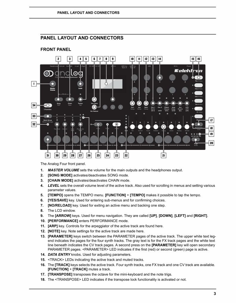
The Analog Four front panel.
1. MASTER VOLUME sets the volume for the main outputs and the headphones output.2. [SONG MODE] activates/deactivates SONG mode.3. [CHAIN MODE] activates/deactivates CHAIN mode.4. LEVEL sets the overall volume level of the active track. Also used for scrolling in menus and setting various
parameter values.5. [TEMPO] opens the TEMPO menu. [FUNCTION] + [TEMPO] makes it possible to tap the tempo.6. [YES/SAVE] key. Used for entering sub-menus and for confirming choices.7. [NO/RELOAD] key. Used for exiting an active menu and backing one step.8. The LCD window.9. The [ARROW] keys. Used for menu navigation. They are called [UP], [DOWN], [LEFT] and [RIGHT].10. [PERFORMANCE] enters PERFORMANCE mode.11. [ARP] key. Controls for the arpeggiator of the active track are found here.12. [NOTE] key. Note settings for the active track are made here.13. [PARAMETER] keys switch between the PARAMETER pages of the active track. The upper white text leg-
end indicates the pages for the four synth tracks. The gray text is for the FX track pages and the white text line beneath indicates the CV track pages. A second press on the [PARAMETER] key will open secondary PARAMETER pages. <PARAMETER> LED indicates if the first (red) or second (green) page is active.
14. DATA ENTRY knobs. Used for adjusting parameters.15. <TRACK> LEDs indicating the active track and muted tracks.16. The [TRACK] keys selects the active track. Four synth tracks, one FX track and one CV track are available.
[FUNCTION] + [TRACK] mutes a track.17. [TRANSPOSE] transposes the octave for the mini-keyboard and the note trigs.18. The <TRANSPOSE> LED indicates if the transpose lock functionality is activated or not.
1
32
33
34
2 3 4 8 9 1410 11 12
21222324252728293031
65 7 15 16
18
17
20
13
19
26

PANEL LAYOUT AND CONNECTORS
4
19. <PATTERN PAGE> LEDs indicate how many pattern pages the active pattern consists of and which pattern page is currently active. The LED flashes on the pattern page currently playing.
20. [PAGE] selects the active pattern page in GRID RECORDING mode. The active pattern page is indicated by the four LEDs above the key. The secondary function accesses the SCALE menu.
21. [KEYBOARD] buttons are used for playing sounds and assigning note values to note trigs. The first key is called [KEYBOARD C1]. The secondary functions of the [KEYBOARD C1] through to [KEYBOARD C2] keys are the KIT, SOUND, TRACK, PATTERN, SONG, CLICK, SWING and GLOBAL menus, respectively.
22. <OCTAVE> LEDs shows the octave transposition for the [KEYBOARD] keys.23. [STOP] stops playback. The secondary function is a paste operation.24. [PLAY] starts the playback of the sequencer. The secondary function is a clear operation.25. [RECORD] key. activates/deactivates GRID RECORDING mode. Starts LIVE RECORDING if held while
pressing [PLAY]. The secondary function is a copy operation.26. <BANK GROUP> LED indicates if bank group A-D or E-H is accessed by the [BANK] keys.27. [BANK D/H] accesses pattern selection for either bank D or H. The secondary function opens the PARAM-
ETER SLIDE menu.28. [BANK C/G] accesses pattern selection for either bank C or G. The secondary function opens the NOTE
SLIDE menu.29. [BANK B/F] accesses pattern selection for either bank B or F. The secondary function opens the ACCENT
menu.30. [BANK A/E] selects a pattern in either bank A or E. The secondary function opens the TRIG MUTE menu.31. [TRIG] keys are used for entering trigs to the sequencer. Also used for choosing patterns.32. <PATTERN MODE> LED indicates the selected PATTERN mode: sequential (off), direct start (red) or direct
jump (green).33. [BANK GROUP] key. Selects the active bank group (A-D or E-H). The secondary function activates differ-
ent PATTERN modes.34. [FUNCTION] key. Press and hold for accessing secondary functions for some of the other keys. Secondary
functions are generally written in red text on the panel.
REAR CONNECTORS
The Analog Four rear connectors:
1. Power on/off switch.2. 12 V DC power in. Use the included Elektron PSU-3 power adapter, connected to a power outlet.3. Full Speed USB 2.0 connection. Use the included A to B USB 2.0 connector cable to a computer host.4. MIDI Thru. Use standard MIDI cable to connect another MIDI unit in chain. Duplicates MIDI In data stream.5. MIDI Out. Use standard MIDI cable to connect to MIDI In of an external MIDI unit in order to control it.6. MIDI In. Use standard MIDI cable to connect MIDI Out of an external MIDI unit to control the Analog Four.7. CV outputs C and D. Connect to external synth with CV inputs. Use either standard 1/4” mono phone plug
or 1/4” insert/Y cable.8. CV outputs A and B. Same recommended connectors as above.9. Audio Input L/R. Use standard 1/4” mono phone plug to input sound from other synthesizers or mixers.10. Main Out L/R. Use either 1/4” mono phone plug (unbalanced connection) or 1/4” stereo (Tip/Ring/Sleeve)
phone plug (balanced connection).11. Headphones Output. Connect standard headphones with 1/4” stereo phone plug.
21 3 4 5 6 7 8 9 10 11

PANEL LAYOUT AND CONNECTORS
5
• Use the included PSU-3 with your Analog Four. It can, using an appropriate power cord, be used all over the globe without the need of voltage converters. Using the wrong type of adapter may damage your unit. Damage caused by the use of incorrect power supply is not covered by war-ranty. Please see “TECHNICAL INFORMATION” on page 74 for details about the Analog Four power supply.
ANALOG FOUR ACCESSORIES
RACK MOUNT KITWhen rack mounted, the Analog Four occupies four standard height units plus additional space, usually about 1 U, which is needed to accommodate cables plugged into the unit. A 1 U empty rack space below the Analog Four is recommended for ventilation purposes.
When assembling the rack mount kit, make sure that you have a Phillips screwdriver of the right size. Use the included M3x6 mm size screws to secure the rack mount consoles on each side of the Analog Four.
ECC-2 CARRYING BAG & PL-2 PROTECTIVE LIDThe carrying bag accommodates one Analog Four. The protective plastic lid is put on top of the Analog Four panel and protects the LCD and the knobs. The protective lid is included with the bag.
CONNECTING THE UNITMake sure you place the Analog Four on a stable support, such as a sturdy table with sufficient cable space, or mount in a rack according to the instructions above. Before you start connecting the Analog Four to other units, make sure all units are switched off.
1. Plug the supplied DC adapter to a power outlet and connect the small plug to the 12 V DC connector of the Analog Four unit.
2. Connect the main out L/R from the Analog Four to your mixer or amplifier.3. If MIDI control of the Analog Four is desired, connect the MIDI OUT port of the device you wish send data
from to the MIDI IN port of the Analog Four. The MIDI THRU port duplicates the data arriving at the MIDI IN port, so it can be used for chaining MIDI units together.
4. Switch on all units. Switch on the Analog Four by pressing the Power rocker switch located at the back of the unit. Before restarting the unit, wait 2 seconds after the LCD backlight goes out.
ANALOG FOUR SIGNAL PATH
6
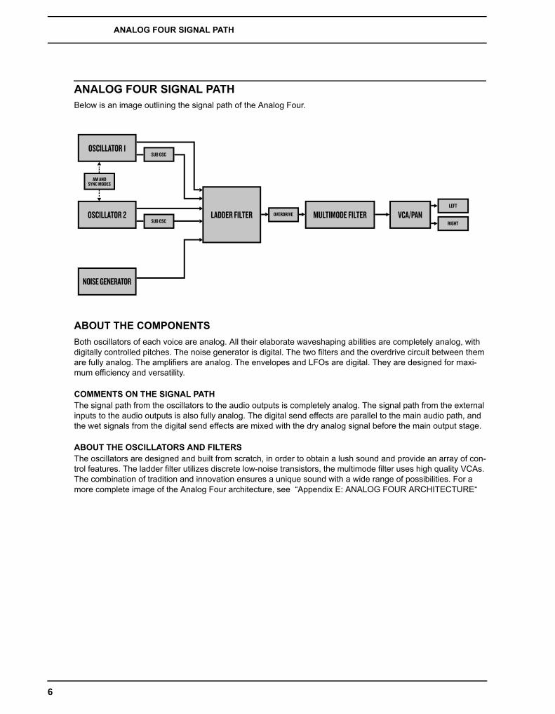
ANALOG FOUR SIGNAL PATHBelow is an image outlining the signal path of the Analog Four.
ABOUT THE COMPONENTSBoth oscillators of each voice are analog. All their elaborate waveshaping abilities are completely analog, with digitally controlled pitches. The noise generator is digital. The two filters and the overdrive circuit between them are fully analog. The amplifiers are analog. The envelopes and LFOs are digital. They are designed for maxi-mum efficiency and versatility.
COMMENTS ON THE SIGNAL PATHThe signal path from the oscillators to the audio outputs is completely analog. The signal path from the external inputs to the audio outputs is also fully analog. The digital send effects are parallel to the main audio path, and the wet signals from the digital send effects are mixed with the dry analog signal before the main output stage.
ABOUT THE OSCILLATORS AND FILTERSThe oscillators are designed and built from scratch, in order to obtain a lush sound and provide an array of con-trol features. The ladder filter utilizes discrete low-noise transistors, the multimode filter uses high quality VCAs. The combination of tradition and innovation ensures a unique sound with a wide range of possibilities. For a more complete image of the Analog Four architecture, see “Appendix E: ANALOG FOUR ARCHITECTURE“
OSCILLATOR 1SUB OSC
OSCILLATOR 2 LADDER FILTER MULTIMODE FILTER VCA/PANSUB OSC RIGHT
LEFT
OVERDRIVE
NOISE GENERATOR
AM ANDSYNC MODES
OVERVIEW OF THE ANALOG FOUR STRUCTURE
7
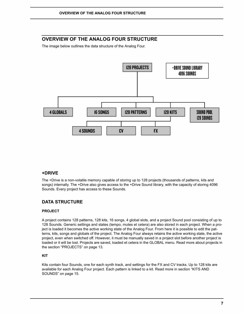
OVERVIEW OF THE ANALOG FOUR STRUCTUREThe image below outlines the data structure of the Analog Four.
+DRIVEThe +Drive is a non-volatile memory capable of storing up to 128 projects (thousands of patterns, kits and songs) internally. The +Drive also gives access to the +Drive Sound library, with the capacity of storing 4096 Sounds. Every project has access to these Sounds.
DATA STRUCTURE
PROJECT
A project contains 128 patterns, 128 kits, 16 songs, 4 global slots, and a project Sound pool consisting of up to 128 Sounds. Generic settings and states (tempo, mutes et cetera) are also stored in each project. When a pro-ject is loaded it becomes the active working state of the Analog Four. From here it is possible to edit the pat-terns, kits, songs and globals of the project. The Analog Four always retains the active working state, the active project, even when switched off. However, it must be manually saved in a project slot before another project is loaded or it will be lost. Projects are saved, loaded et cetera in the GLOBAL menu. Read more about projects in the section “PROJECTS” on page 13.
KIT
Kits contain four Sounds, one for each synth track, and settings for the FX and CV tracks. Up to 128 kits are available for each Analog Four project. Each pattern is linked to a kit. Read more in section “KITS AND SOUNDS” on page 15.
128 PROJECTS +DRIVE SOUND LIBRARY4096 SOUNDS
4 GLOBALS 16 SONGS 128 PATTERNS 128 KITS
4 SOUNDS FXCV
SOUND POOL128 SOUNDS

OVERVIEW OF THE ANALOG FOUR STRUCTURE
8
SOUNDA Sound consists of stored synth track parameter settings. Each synth track can host one Sound. Sounds can be stored either in the Sound pool of the active project or in the +Drive Sound library. The Sound pool contains 128 Sounds and the +Drive library can consist of 4096 Sounds. Read more in section “KITS AND SOUNDS” on page 15.
BANKEight banks exist for each project and each bank contains 16 patterns. Read more in section “THE SEQUENCER” on page 29.
PATTERNFor each of the 8 banks 16 patterns are available, which means 128 patterns are always available. A pattern consists of sequencer data like trigs, parameter locks, time signature and individual track length for the synth tracks and the FX and CV tracks, as well as ARP and NOTE page settings. Read more in section “THE SEQUENCER” on page 29.
SONG16 songs are available for each project. They are used to structure the playback of patterns. Read more about songs in the section “SONGS” on page 44.
CHAINSA chain is a sequence of patterns. Up to 256 pattern slots are possible to allocate between 64 chains. Chains are covered in detail on page 43.
GLOBALThe GLOBAL menu is where you save, load and manage projects, handle SysEx data and perform OS upgrades. It also contains general settings for the synth and sequencer as well as MIDI and CV configurations. Four global slots are available for every project, each with its own individual settings. Read more about the global settings in the section “GLOBAL MENU” on page 46.
ABOUT THE TRACK TYPES
THE SYNTH TRACKSThe synth tracks consist of track 1-4. To edit one of them, press [TRACK] key 1-4. Sounds are loaded to the synth tracks. Sounds can be played polyphonically.
THE FX TRACKThe FX track controls the Analog Four internal send effects. To edit the FX track, press the [TRACK] key 5.
THE CV TRACKThe CV track is used for controlling external equipment capable of receiving analog CV and Gate signals. To edit the CV track, press [TRACK] key 6.
EDITING THE TRACKSThe six [PARAMETER] keys open pages that are used for editing the tracks. They contain different parameters depending on the track type. Edit parameters using the DATA ENTRY knobs. Press and turn a knob to adjust parameters in larger increments.
THE USER INTERFACE
9
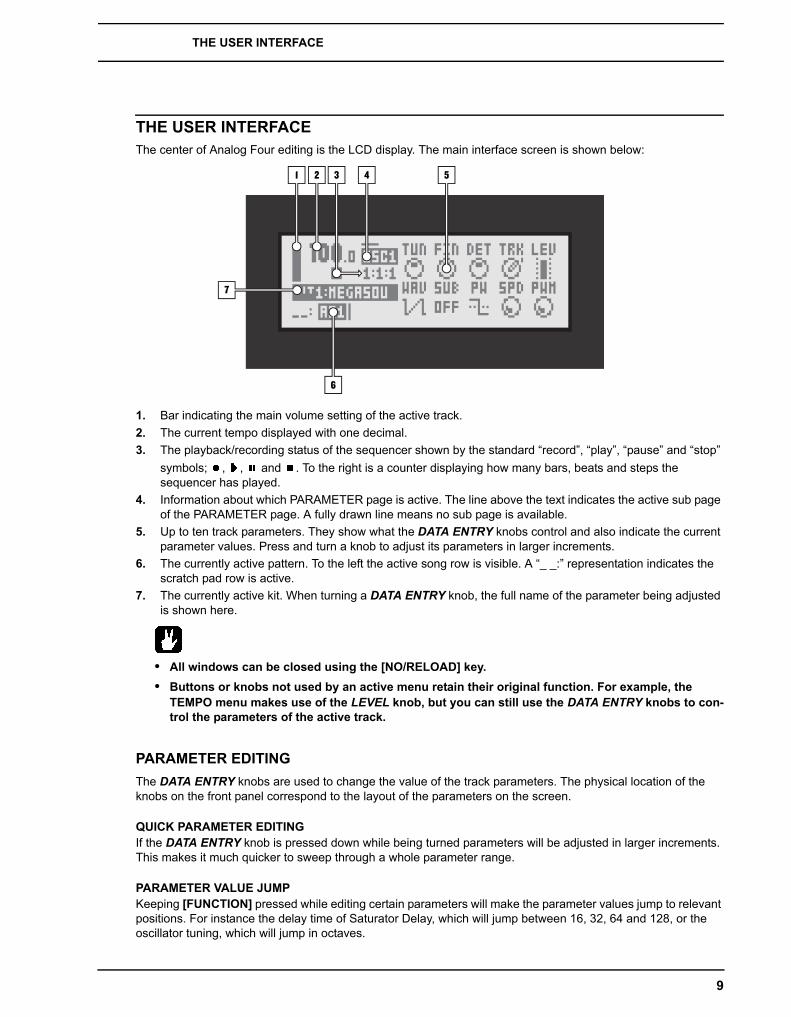
THE USER INTERFACEThe center of Analog Four editing is the LCD display. The main interface screen is shown below:
1. Bar indicating the main volume setting of the active track.2. The current tempo displayed with one decimal.3. The playback/recording status of the sequencer shown by the standard “record”, “play”, “pause” and “stop”
symbols; , , and . To the right is a counter displaying how many bars, beats and steps the sequencer has played.
4. Information about which PARAMETER page is active. The line above the text indicates the active sub page of the PARAMETER page. A fully drawn line means no sub page is available.
5. Up to ten track parameters. They show what the DATA ENTRY knobs control and also indicate the current parameter values. Press and turn a knob to adjust its parameters in larger increments.
6. The currently active pattern. To the left the active song row is visible. A “_ _:” representation indicates the scratch pad row is active.
7. The currently active kit. When turning a DATA ENTRY knob, the full name of the parameter being adjusted is shown here.
• All windows can be closed using the [NO/RELOAD] key.• Buttons or knobs not used by an active menu retain their original function. For example, the
TEMPO menu makes use of the LEVEL knob, but you can still use the DATA ENTRY knobs to con-trol the parameters of the active track.
PARAMETER EDITINGThe DATA ENTRY knobs are used to change the value of the track parameters. The physical location of the knobs on the front panel correspond to the layout of the parameters on the screen.
QUICK PARAMETER EDITINGIf the DATA ENTRY knob is pressed down while being turned parameters will be adjusted in larger increments. This makes it much quicker to sweep through a whole parameter range.
PARAMETER VALUE JUMPKeeping [FUNCTION] pressed while editing certain parameters will make the parameter values jump to relevant positions. For instance the delay time of Saturator Delay, which will jump between 16, 32, 64 and 128, or the oscillator tuning, which will jump in octaves.
1 2 4 5
7
6
3

THE USER INTERFACE
10
QUICK SCROLLINGIn most menus quick scrolling is available. Press [FUNCTION] + the [UP] or [DOWN] arrow keys to move the cursor one menu page at a time.
COPY, CLEAR AND PASTECopy, clear and paste commands are available in a lot of contexts. A copy operation is performed by pressing [FUNCTION] + [REC]. A paste operation is performed by pressing [FUNCTION] + [STOP]. A clear operation is performed by pressing [FUNCTION] + [PLAY]. Paste and clear operations can be undone by repeating the but-ton press combination. See the different sections in the manual for more information about where these com-mands are available.
THE NAMING MENUThe naming procedure is identical for the various naming menus that exist.
The [LEFT] and [RIGHT] arrow keys are used to navigate between the letters. Turning the LEVEL knob or pressing the [UP] or [DOWN] arrow keys select the letter. [FUNCTION] + [NO/RELOAD] will erase letters.
POP-UP MENU NAMINGWhile in a NAMING menu it is possible to open a pop up-menu displaying all available letters, symbols and dig-its. Entering characters in the pop up-menu is often a considerably faster naming method. When a NAMING menu is open, press the [FUNCTION] key to access the pop up-menu.
While keeping [FUNCTION] pressed use the [ARROW] keys to navigate to the character you want to insert. Once there, release [FUNCTION] to insert the character.
• Copy, paste and clear commands are available in the naming menus.
THE USER INTERFACE
11
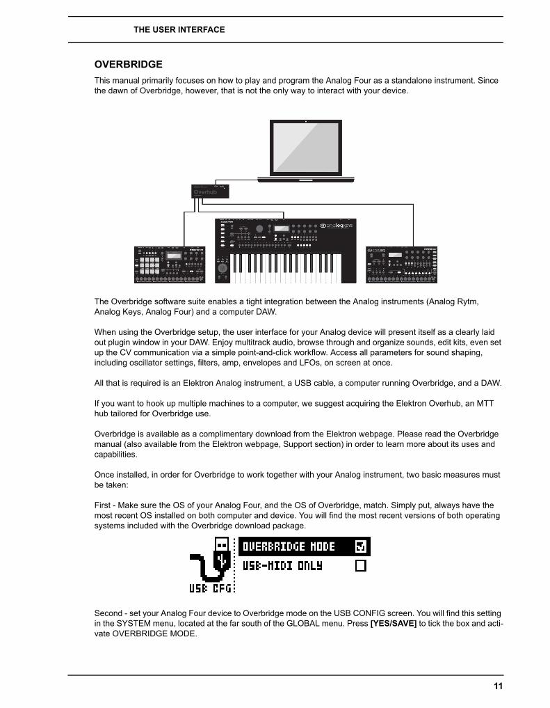
OVERBRIDGEThis manual primarily focuses on how to play and program the Analog Four as a standalone instrument. Since the dawn of Overbridge, however, that is not the only way to interact with your device.
The Overbridge software suite enables a tight integration between the Analog instruments (Analog Rytm, Analog Keys, Analog Four) and a computer DAW.
When using the Overbridge setup, the user interface for your Analog device will present itself as a clearly laid out plugin window in your DAW. Enjoy multitrack audio, browse through and organize sounds, edit kits, even set up the CV communication via a simple point-and-click workflow. Access all parameters for sound shaping, including oscillator settings, filters, amp, envelopes and LFOs, on screen at once.
All that is required is an Elektron Analog instrument, a USB cable, a computer running Overbridge, and a DAW.
If you want to hook up multiple machines to a computer, we suggest acquiring the Elektron Overhub, an MTT hub tailored for Overbridge use.
Overbridge is available as a complimentary download from the Elektron webpage. Please read the Overbridge manual (also available from the Elektron webpage, Support section) in order to learn more about its uses and capabilities.
Once installed, in order for Overbridge to work together with your Analog instrument, two basic measures must be taken:
First - Make sure the OS of your Analog Four, and the OS of Overbridge, match. Simply put, always have the most recent OS installed on both computer and device. You will find the most recent versions of both operating systems included with the Overbridge download package.
Second - set your Analog Four device to Overbridge mode on the USB CONFIG screen. You will find this setting in the SYSTEM menu, located at the far south of the GLOBAL menu. Press [YES/SAVE] to tick the box and acti-vate OVERBRIDGE MODE.

QUICK START
12
QUICK STARTThis quick start will guide you through some of the basic operations to allow you to start using the Analog Four right away. First connect it as described in section “CONNECTING THE UNIT”, on page 5.
PLAYING THE FACTORY PRESETSThe Analog Four is shipped with several preset patterns, kits and Sounds. To immediately start experimenting with the Analog Four, just follow the instructions below.
1. Switch on the Analog Four.2. Press [PLAY] to listen to pattern A01.3. Select pattern A02, which is the second demo pattern, by first making sure bank group A-D is selected. The
<BANK GROUP> indicates the selected bank group. If A-D is not selected, press the [BANK GROUP] key.4. Pressing [BANK A/E] + [TRIG] key 2 will make pattern A02 play once the currently playing pattern finishes.
Pattern A03 is selected by pressing [BANK A/E] + [TRIG] key 3 and so on.5. Mute tracks by pressing [FUNCTION] + the [TRACK] key of the track you want to mute. Unmute by repeat-
ing the procedure.6. Press [STOP] to stop playback.
PERFORMANCE MODEThe PERFORMANCE mode makes it possible for the DATA ENTRY knobs to control several PARAMETER page parameters at once. These parameter mappings are called a parameter macro.
1. Make sure a pattern is playing.2. Press the [PERFORMANCE] key to access PERFORMANCE mode.3. Turn the DATA ENTRY knobs and listen how the sound of pattern changes.
ADJUSTING PARAMETERSEach track contains six PARAMETER pages. There parameters affecting the sound of track are found.
1. Make sure a pattern is playing.2. Press the [TRACK] key of one of the four synth tracks.3. To change the cutoff of the ladder filter, press the [FILTERS] key. The FILTERS page will open. The param-
eter labelled FRQ changes the cutoff of the ladder filter. Turn DATA ENTRY knob A to change the parame-ter value.
4. Try out the rest of the PARAMETER page parameters to experiment with the sound shaping possibilities.5. To reload the Sound to its original state, press [NO/RELOAD] + [KEYBOARD D1].6. To reload the whole kit to its original state, press [NO/RELOAD] + [KEYBOARD C1].

PROJECTS
13
PROJECTSA project is the top level structure of the Analog Four. A project contains 128 patterns, 128 kits, 16 songs, 4 global slots, and a project Sound pool consisting of up to 128 Sounds. Projects are handy when for example wanting to save a specific setup for a live performance or for managing a select number of compositions. The +Drive can store 128 projects.
When a project is loaded it becomes the active working state of the Analog Four, independent of the +Drive. Analog Four will keep track of what project slot the active project was loaded from. When a project is loaded it is possible to edit its patterns, kits, songs, and globals. The active project and any changes made to it are automat-ically remembered by the Analog Four, allowing you to edit patterns, kits et cetera, switch off the unit, switch it on again and have everything sound as it did prior to the power cycling. Please note that changes are not automat-ically written to the +Drive. To store the active working state of the project to a +Drive slot, the project needs to be saved manually.
PROJECT MENUProjects are managed in the PROJECT menu, located in the GLOBAL menu. Open the GLOBAL menu by pressing [FUNCTION] + [KEYBOARD C2].
Scroll the list by using [UP]/[DOWN] or the LEVEL knob and select PROJECT. Open the menu by pressing [YES/SAVE].
LOAD PROJECT opens a project selection screen where you choose a project to be loaded. Note that the active project will not be saved before loading the new project. This menu can be accessed directly by pressing and holding [FUNCTION] + [KEYBOARD C2] for a second. If you wish to create a new project, select CREATE NEW at the very bottom of the list. The new project will be a blank slate.
SAVE PROJECT opens a project selection screen where you choose a slot to save the active project to.

PROJECTS
14
• The slot the currently active project is linked to is indicated by a small arrow in front of the project name.
• Projects can be copied/cleared/pasted in the LOAD PROJECT and SAVE PROJECT menus.• A lock symbol indicates the project is write protected.
PROJECT MANAGER launches the PROJECT MANAGER menu. Selecting a project in this menu and press-ing the [RIGHT] arrow key will bring up a list of commands.
CLEAR resets the project slot to a clean state.
INIT NEW initializes an empty file slot with a clean project. This operation is only available for empty project slots.
DELETE removes the project from the slot.
RENAME opens a screen where you can rename the project file.
LOAD FROM loads the selected project to the active project. Remember that the active pro-ject will be overwritten!
SAVE TO saves the active project to the selected slot.
TOGGLE toggles write protection on or off. Write protected projects can not be overwritten, renamed or erased. A write protected project is indicated by a lock symbol.
• Multiple projects can be selected and deselected by highlighting them and pressing [YES/SAVE].• The slot the currently active project is linked to is indicated by a small arrow in front of the project
name.• Projects can be copied/cleared/pasted in this menu.
• LOAD FROM in the PROJECT MANAGER will overwrite the active project. Be sure to save your project before you load another.

KITS AND SOUNDS
15
KITS AND SOUNDSKits and Sounds are the basic building blocks of Analog Keys soundcrafting. A kit is a collection of Sound, FX and CV track parameter settings. A Sound is essentially a synth track patch, made up by subtractive synthesis from the oscillators through the filters via its various parameter settings. Each of the 4 synth tracks contains one Sound.
Kits and Sounds are separated, meaning kits do not necessarily have to use any saved Sounds. When saving a kit, the PARAMETER page settings of the synth tracks, i.e. the settings that constitute a Sound, will be saved together with the kit. The synth track PARAMETER page settings of a kit can of course be saved as individual Sounds as well. When loading a Sound, it will become a part of the kit. Changes made to the track Sound will not affect the loaded Sound, only the kit. A specific kit is always assigned to a pattern which controls the play-back of the kit.
A Kit contains:
• Sound settings for the 4 synth tracks.• FX track parameter settings.• CV track parameter settings.• LEVEL settings for the Synth and FX tracks.• PERFORMANCE mode parameter settings. • Polyphony settings.
A Sound contains:
• Settings for the PARAMETER pages of a synth track.
• The LCD graphics in the left part of the screen shows the name of the currently active kit. When the [TRACK] keys are pressed, this information will briefly change to reflect the name of the track. In the case of the synth tracks, the name of the track Sound will be displayed.
• Note that several patterns may use the same kit. Changes you make to the kit while editing one of the patterns will directly affect how the other patterns sound as well. Remember to save the kit to a new location if you wish to avoid this.
THE +DRIVE SOUND LIBRARY AND THE SOUND POOLSounds can be loaded to a kit from either the +Drive Sound library or the Sound pool of the active project. The difference between the two is that the +Drive Sound library has the capacity of 4096 Sounds, available to all pro-jects, while a Sound pool is a part of a project and limited to 128 Sounds. The major benefit of Sounds loaded to the Sound pool is the possibility for them to be Sound locked. This feature is not available for the Sounds in the +Drive Sound library. Read more about Sound locking on page 38.

KITS AND SOUNDS
16
KIT MENUIn the KIT menu commands relating to kits are found, most importantly kit save and load. Open the menu by pressing [FUNCTION] + [KEYBOARD C1]. Use the [UP] and [DOWN] arrow keys to move between the com-mands. Press [YES/SAVE] to confirm your selection. Exit the menu by pressing [NO/RELOAD].
RELOAD KIT will reload the either the active kit, reverting it to its saved status, or all kits. Using the [LEFT] and [RIGHT] keys selects whether only the active kit or all kits will be reloaded. [NO/RELOAD] + [KEYBOARD C1] offers a short cut to reloading the active kit.
LOAD KIT opens a menu where one of the up to 128 saved kits can be loaded. When this menu is opened the kit list will appear. The active kit is indicated by inverted graphics. Select the kit to be loaded by using the [ARROW] keys or the LEVEL knob. [LEFT]/[RIGHT] will quickly scroll between the menu pages. Once a kit has been selected, press [YES/SAVE] to load it. The loaded kit will be linked to the active pattern. Loading the active kit will reload it.
SAVE KIT is where all the current, kit related, settings can be saved as a kit. The saved kit will be linked to the active pattern. [YES/SAVE] + [KEYBOARD C1] offers a short cut to this command.
When this menu is opened the kit list will appear. The active kit is indicated by inverted graphics. Select the slot to which the kit will be saved by using the [ARROW] keys or the LEVEL knob. Press [YES/SAVE] to save to the selected slot. The NAMING menu, covered on page 10, will appear.
CLEAR KIT will clear the content of the currently loaded kit, basically initializing it. When selecting this option a prompt will appear. Press [YES/SAVE] to clear the kit or [NO/RELOAD] to cancel the operation. Note that no kit information will be permanently lost until the kit is saved to the same kit slot it was loaded from.
PERFORMANCE opens the PERFORMANCE SETUP menu, covered on page 17.
POLY CONFIG opens the POLYPHONY CONFIGURATION menu. See page 19.
VOICE ROUTING accesses VOICE ROUTING. See page 20
• Copy, clear and paste operations are available in the LOAD KIT, SAVE KIT and PERFORMANCE SETUP menus.
• Press and turn the LEVEL knob to increase scrolling speed in the LOAD KIT and SAVE KIT menus.
• Once you have assembled a kit you like, you are advised to save it.
• Kits not used by any patterns are indicated by an asterisk after the kit name.
PERFORMANCE MODEThe PERFORMANCE mode makes it possible to control five track parameters, that can be chosen from any track, at the same time by turning a single DATA ENTRY knob. This is called a performance macro. Track mut-ing and an overview of all synth and FX track levels are available in this mode as well. PERFORMANCE mode settings are saved as a part of a kit.
KITS AND SOUNDS
17
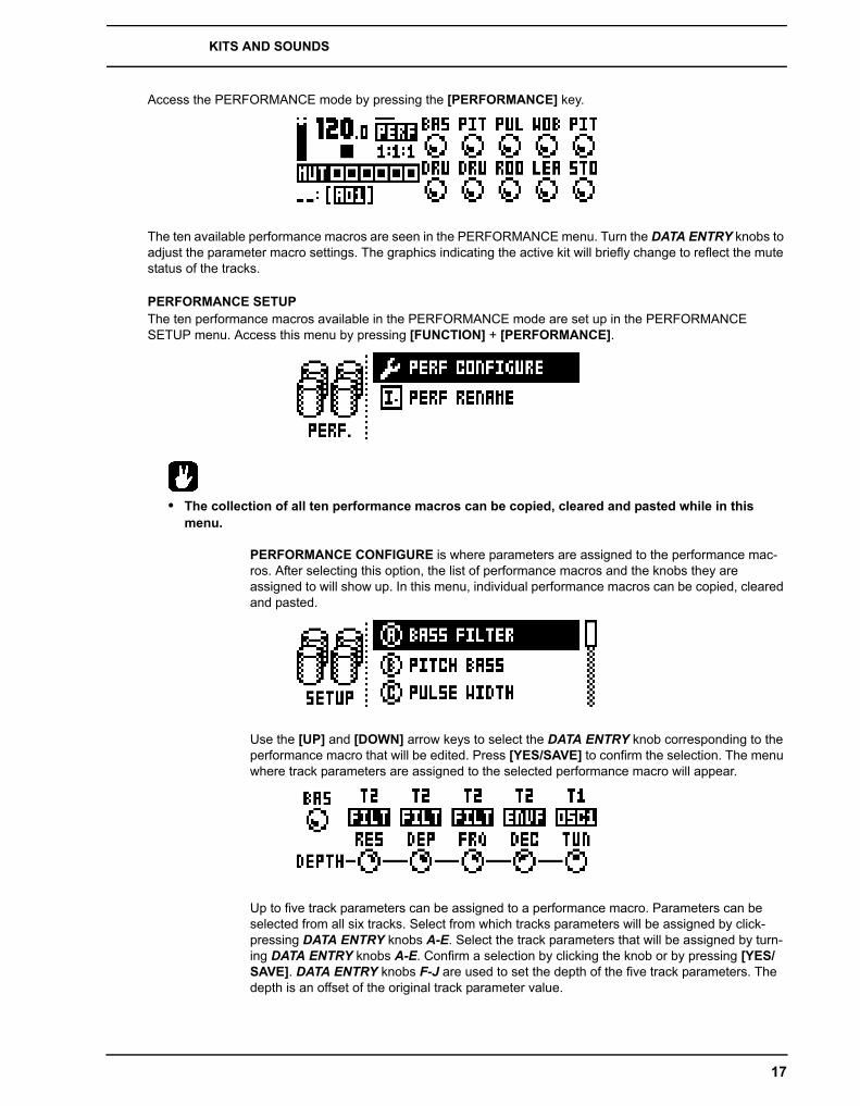
Access the PERFORMANCE mode by pressing the [PERFORMANCE] key.
The ten available performance macros are seen in the PERFORMANCE menu. Turn the DATA ENTRY knobs to adjust the parameter macro settings. The graphics indicating the active kit will briefly change to reflect the mute status of the tracks.
PERFORMANCE SETUPThe ten performance macros available in the PERFORMANCE mode are set up in the PERFORMANCE SETUP menu. Access this menu by pressing [FUNCTION] + [PERFORMANCE].
• The collection of all ten performance macros can be copied, cleared and pasted while in this menu.
PERFORMANCE CONFIGURE is where parameters are assigned to the performance mac-ros. After selecting this option, the list of performance macros and the knobs they are assigned to will show up. In this menu, individual performance macros can be copied, cleared and pasted.
Use the [UP] and [DOWN] arrow keys to select the DATA ENTRY knob corresponding to the performance macro that will be edited. Press [YES/SAVE] to confirm the selection. The menu where track parameters are assigned to the selected performance macro will appear.
Up to five track parameters can be assigned to a performance macro. Parameters can be selected from all six tracks. Select from which tracks parameters will be assigned by click-pressing DATA ENTRY knobs A-E. Select the track parameters that will be assigned by turn-ing DATA ENTRY knobs A-E. Confirm a selection by clicking the knob or by pressing [YES/SAVE]. DATA ENTRY knobs F-J are used to set the depth of the five track parameters. The depth is an offset of the original track parameter value.
KITS AND SOUNDS
18
By default the parameter macro knob spans a parameter value range of 0-127. A parameter macro value of 0 will not introduce any changes to the sound. Press the LEVEL knob to make the performance macro knob work in a bipolar fashion, meaning the parameter macro value range will go from -64 to +63.
While a pattern or Sound is playing, turn the LEVEL knob to preview how the performance macro affects the sound.
• PERFORMANCE mode parameters are not possible to parameter lock.• If for example the depth of the OSC1 PITCH of track 1 is set to 63 and the parameter macro is set
to a non-bipolar mode, turning the parameter macro knob to 127 will introduce a parameter value offset of +63 to the OSC1 PITCH parameter. If the macro knob is set to a bipolar mode, turning the parameter macro value to +63 will introduce a parameter value offset of +63 to the OSC1 PITCH parameter. Conversely, turning the parameter macro knob to -64 will introduce a parameter value offset of -64 to the OSC1 PITCH parameter.
• Use parameter macros to affect the most relevant parameters when playing live. By carefully set-ting up parameter macros you might find that you don't have to leave this mode at all during your live set.
PERFORMANCE RENAME allows performance macro knobs to be named. Use the [UP] and [DOWN] arrow keys to select the DATA ENTRY knob corresponding to the performance macro that will be named. Press [YES/SAVE] to confirm the selection. The NAMING menu will appear.
PERFORMANCE MUTETrack muting, also covered on page 28, can be carried out while in PERFORMANCE mode. When in PERFOR-MANCE mode, [TRIG] keys 1-6 mute the tracks. An outlined square in the track mute section and a full bright <TRIG> LED means a track is audible. A minus sign and a quarter-bright <TRIG> LED indicates the track is muted. While holding [FUNCTION] and pressing the six first [TRIG] keys, the mute changes will be held until [FUNCTION] is released. A track that is currently muted, but will be unmuted when [FUNCTION] is released, is indicated by a “+” sign and a half-bright <TRIG> LED. A track that is currently not muted, but will be muted when [FUNCTION] is released, is indicated by an asterisk and a half-bright, blinking <TRIG> LED.
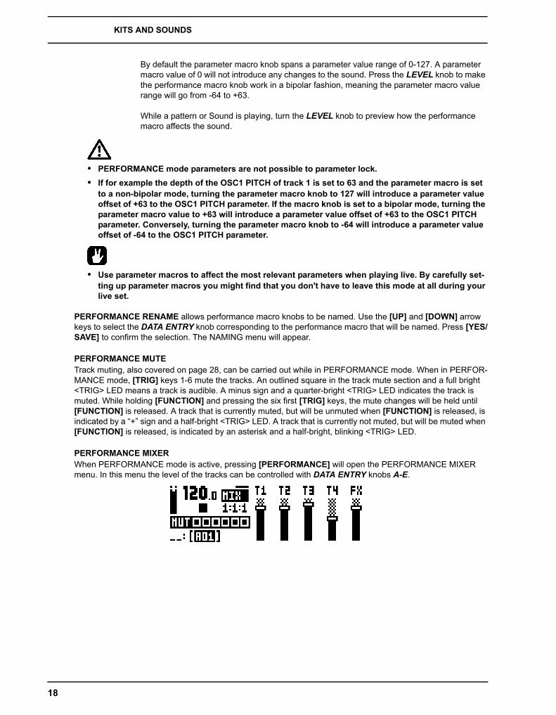
PERFORMANCE MIXERWhen PERFORMANCE mode is active, pressing [PERFORMANCE] will open the PERFORMANCE MIXER menu. In this menu the level of the tracks can be controlled with DATA ENTRY knobs A-E.

KITS AND SOUNDS
19
POLYPHONYFour voice polyphony can be configured by selecting POLY CONFIG in the KIT menu. The Analog Four is capa-ble of four voice multitimbral polyphony (or unison). This is possible due to the powerful sound engine which is able to change sound instantly and allow completely dynamic voice allocation (see figure below). The sequencer is fully polyphonic, allowing overlapping notes and chords to be programmed on the tracks. Any track can play up to four notes using its own track sound. Notes are distributed to the synth voices according to the selected allocation method. Any of the synth voices can also be poly-disabled, allowing tracks to have their dedicated, monophonic synth voice available at all times. The poly configuration is stored per kit, for maximum flexibility, allowing up to 128 different poly configurations per project.
POLYPHONY CONFIGURATION
The settings for up to four voice polyphony are found in the POLY CONFIG menu found at the bottom of the KIT menu (accessed by pressing [FUNCTION] + [C1]).
VOICES Select any combination of the four voices to be poly activated by using the [LEFT] and [RIGHT] arrow keys. Tick or untick a box by pressing the [YES/SAVE] button.To activate/deactivate voice 1-4 directly, press [TRIG] key 1 through 4. When in the POLY CONFIG menu, the red LEDs above [TRIG] key 1-4 on the front panel will be half-bright. When a voice is activated, the corresponding LED will be full-bright. Voices that are not set to be poly ena-bled will be dedicated monophonic voices for their corresponding tracks. These will never be used for polyphonic playback. Voices that are poly enabled can be allocated dynamically by any of the poly enabled tracks.
ALLOCATION changes the allocation method of the poly voices, or sets all poly enabled voices to play simultaneously (RESET, ROTATE, REASSIGN or UNISON, respectively). Select method with the [LEFT] and [RIGHT] arrow keys. For a visual explanation of the differ-ent allocation methods, see illustrations on page 21 and page 22.
The LEDs above the first four [TRIG] keys will flash to show voice activity depending on the selected method. Select method, play a few notes on the keyboard and watch the LEDs to get an immediate, visual impression of how the different allocation methods work.
RESET Picks the first available voice in increasing order, starting from track voice 1, for every new overlapping note played.
MONOPHONIC POLYPHONIC
TRACK 1
TRACK 2
TRACK 3
TRACK 4
VOICE A
VOICE B
VOICE C
VOICE D
TRACK 1
TRACK 2
TRACK 3
TRACK 4
VOICE A
VOICE B
VOICE C
VOICE D
KITS AND SOUNDS
20
ROTATE For every new coinciding note played the voices are allocated in a cyclic manner.
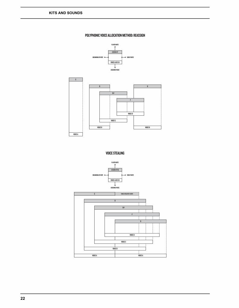
REASSIGN Uses the same voice as last time for every note played as long as its unused. Otherwise the least recently used voice is used for the new note.
UNISON Uses all voices to play the same note. Employs the adjustable parameters DETUNE and PAN SPREAD shown below.
USE TRK SOUNDS forces the selected voices to use the Sounds of the four tracks, instead of letting the voices use the played Sound in a dynamic way. Tick/untick box to activate/deacti-vate using the [YES/SAVE] key or the [LEFT] and [RIGHT] arrow keys.
UNISON DETUNE sets the offset (0-127) by which the selected unison voices will be detuned. Decrease or increase the offset with the [LEFT] and [RIGHT] arrow keys.
UNISON PAN SPREAD set the width of the pan spread (0-127) around the center point of the unison sound. Use the [LEFT] and [RIGHT] arrow keys to set the value.
If no free voice is found, the least recently used voice is stolen and used for the played note. See illustration on page 22. This applies to all allocation methods described above.
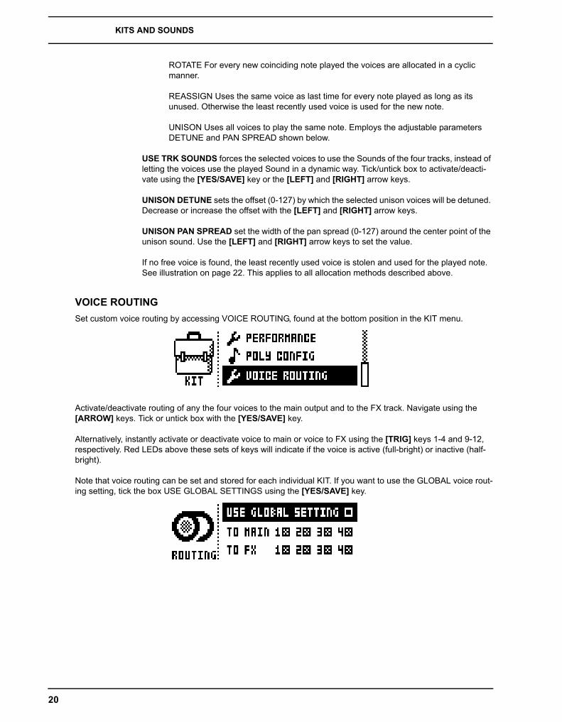
VOICE ROUTINGSet custom voice routing by accessing VOICE ROUTING, found at the bottom position in the KIT menu.
Activate/deactivate routing of any the four voices to the main output and to the FX track. Navigate using the [ARROW] keys. Tick or untick box with the [YES/SAVE] key.
Alternatively, instantly activate or deactivate voice to main or voice to FX using the [TRIG] keys 1-4 and 9-12, respectively. Red LEDs above these sets of keys will indicate if the voice is active (full-bright) or inactive (half-bright).
Note that voice routing can be set and stored for each individual KIT. If you want to use the GLOBAL voice rout-ing setting, tick the box USE GLOBAL SETTINGS using the [YES/SAVE] key.

KITS AND SOUNDS
21
POLYPHONIC VOICE ALLOCATION METHOD: RESET
C/D/D#/F
C
D
D#
F
VOICE B
VOICE C
VOICE B
VOICE A/B/C/D
VOICE A
D#
VOICE A
PLAYED NOTE
ASSIGNED VOICE
BEGINNING OF NOTE END OF NOTE
(SHOWN AS PLAYED FROM TRACK 1)
POLYPHONIC VOICE ALLOCATION METHOD: ROTATE
C/D/D#/F
VOICE A/B/C/D
PLAYED NOTE
ASSIGNED VOICE
BEGINNING OF NOTE END OF NOTE
C
D
D#
F
VOICE D
VOICE C
VOICE B
D
VOICE AVOICE A
KITS AND SOUNDS
22
POLYPHONIC VOICE ALLOCATION METHOD: REASSIGN
C/D/D#/F
C
D
D#
F
VOICE D
VOICE C
VOICE B
D
VOICE B
VOICE A/B/C/D
VOICE A
PLAYED NOTE
ASSIGNED VOICE
BEGINNING OF NOTE END OF NOTE
VOICE STEALING
C/D/D#/F/G
C VOICE STOLEN BY G NOTE
D
D#
F
G
VOICE C
VOICE D
VOICE B
VOICE A/B/C/D
VOICE A VOICE A
PLAYED NOTE
ASSIGNED VOICE
BEGINNING OF NOTE END OF NOTE
KITS AND SOUNDS
23
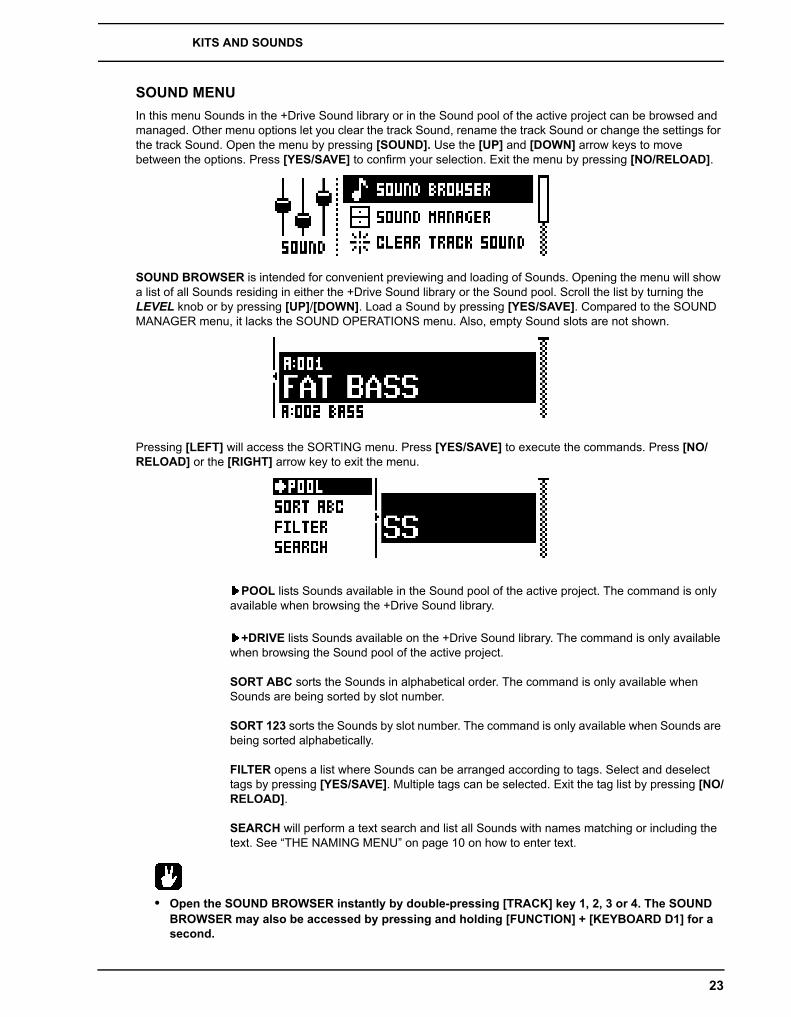
SOUND MENUIn this menu Sounds in the +Drive Sound library or in the Sound pool of the active project can be browsed and managed. Other menu options let you clear the track Sound, rename the track Sound or change the settings for the track Sound. Open the menu by pressing [SOUND]. Use the [UP] and [DOWN] arrow keys to move between the options. Press [YES/SAVE] to confirm your selection. Exit the menu by pressing [NO/RELOAD].
SOUND BROWSER is intended for convenient previewing and loading of Sounds. Opening the menu will show a list of all Sounds residing in either the +Drive Sound library or the Sound pool. Scroll the list by turning the LEVEL knob or by pressing [UP]/[DOWN]. Load a Sound by pressing [YES/SAVE]. Compared to the SOUND MANAGER menu, it lacks the SOUND OPERATIONS menu. Also, empty Sound slots are not shown.
Pressing [LEFT] will access the SORTING menu. Press [YES/SAVE] to execute the commands. Press [NO/RELOAD] or the [RIGHT] arrow key to exit the menu.
POOL lists Sounds available in the Sound pool of the active project. The command is only available when browsing the +Drive Sound library.
+DRIVE lists Sounds available on the +Drive Sound library. The command is only available when browsing the Sound pool of the active project.
SORT ABC sorts the Sounds in alphabetical order. The command is only available when Sounds are being sorted by slot number.
SORT 123 sorts the Sounds by slot number. The command is only available when Sounds are being sorted alphabetically.
FILTER opens a list where Sounds can be arranged according to tags. Select and deselect tags by pressing [YES/SAVE]. Multiple tags can be selected. Exit the tag list by pressing [NO/RELOAD].
SEARCH will perform a text search and list all Sounds with names matching or including the text. See “THE NAMING MENU” on page 10 on how to enter text.
• Open the SOUND BROWSER instantly by double-pressing [TRACK] key 1, 2, 3 or 4. The SOUND BROWSER may also be accessed by pressing and holding [FUNCTION] + [KEYBOARD D1] for a second.

KITS AND SOUNDS
24
SOUND MANAGER can be regarded as a more powerful variant of the SOUND BROWSER. Here Sounds can be saved, loaded, tagged et cetera. Opening the menu will show a list of all Sounds residing in either the +Drive Sound library or the Sound pool. Scroll the list by turning the LEVEL knob or by pressing [UP]/[DOWN].
Pressing [LEFT] will access the SORTING menu. The available commands are the same as those found in the SORTING menu of the SOUND BROWSER. Read more about the SORTING menu on page 23.
Pressing [RIGHT] will access the SOUND OPERATIONS menu. The available operations will affect the cur-rently highlighted Sound. Press [YES/SAVE] to apply the commands to the selected Sound. Press [NO/RELOAD] or the [LEFT] arrow key to exit the menu.
LOAD TO TRACK loads the selected Sound to the active track and makes it a part of the active kit.
COPY TO POOL copies the selected Sounds to the first free slots of the active project Sound pool. This command is only available when browsing the +Drive Sound library.
COPY TO +DRIVE copies the selected Sounds to the first free slots of the +Drive Sound library. This command is only available when browsing the Sound pool of the active project.
STORE TRACK SOUND saves the active track Sound to the selected slot. [YES/SAVE] + [KEYBOARD D1] offers a short cut to this operation.
RENAME will rename the selected Sound.
EDIT TAGS opens a menu where Sounds can be tagged. Sounds can have any number of tags, but only the two first will be shown in the Sound list. Apply or remove tags by pressing [YES/SAVE].
DELETE will delete the Sound.
TOGGLE will enable or disable write protection for the selected Sounds. When a Sound is write protected it cannot be overwritten, renamed, tagged or deleted.
SEND SYSEX sends the selected Sounds as SysEx data.
SELECT ALL selects all Sounds in the list.
DESELECT ALL deselects all Sounds in the list.

KITS AND SOUNDS
25
• Sounds residing in the +Drive Sound library are organized into 16 banks, ranging from A to P. Each bank can contain 256 Sounds. Use the [TRIG] keys to view only Sounds located in a specific bank.
• You can preview the currently selected Sound using the mini keyboard or via the MIDI auto-chan-nel. The Sound will be played through the active track. Please note that if the previewed Sound is routed through the effects, the current effects settings will affect it.
• Several Sounds can be simultaneously affected by the commands available in the SOUND OPER-ATIONS menu. Select/deselect individual Sounds by highlighting them and pressing [YES/SAVE].
• Press [FUNCTION] + [UP]/[DOWN] for faster scrolling in the Sound list.
CLEAR TRACK SOUND will set the PARAMETER page parameters of the active track to their default values. When selecting this option a prompt will appear. Press [YES/SAVE] to initialize the parameters or [NO/RELOAD] to cancel the operation. Note that no parameter information will be permanently lost until the kit is saved to the same slot it was loaded from.
RENAME TRACK SOUND opens a NAMING menu where the Sound of the active track can be renamed.
SOUND SETTINGS opens a menu where various Sound related settings are found. Use the [UP]/[DOWN] arrow keys or the LEVEL knob to scroll in the menu. Use the [LEFT]/[RIGHT] arrow keys to change the settings The parameters assignable to the controllers (modulation wheel, breath controller et cetera) will vary according to the type of track that is active: Synth, FX or CV.
OSCILLATOR DRIFT will when activated introduce a very subtle pitch drift to the oscillators, which can increase their perceived “warmth”.
F1 RESONANCE BOOST increases the amount of resonance from the first filter. Affects res-onance and gain of both upper and lower frequencies.
• F1 RESONANCE BOOST will introduce more resonant overtones into the overdrive. Very handy when you want your machine to howl, but be careful! It may cause peaks that can harm your ears if played at a high volume.
LEGATO MODE can turned either off or on. When the mode is activated, envelopes will not be retrigged for overlapping notes played manually on the [KEYBOARD] keys or incoming MIDI notes trigging Sounds. Note that notes on the sequencer are not affected.
PORTAMENTO will when active make the pitch slide between notes. The settings only affect notes played manually on the [KEYBOARD] keys or incoming MIDI notes trigging Sounds. Notes on the sequencer will not be affected. For sliding sequencer notes, the NOTE SLIDE menu, covered on page 39, is used.
• OFF turns portamento off. No played notes will be affected.
• ON turns portamento on. All played notes will be affected.

KITS AND SOUNDS
26
• LEGATO activates portamento for overlapping notes only. LEGATO MODE needs to be activated for this setting to function.
VELOCITY TO VOL selects how MIDI velocity will affect volume when playing the Sound from a MIDI keyboard.
• OFF means velocity will not affect the volume of the Sound.
• LOG will apply a logarithmic velocity curve. The volume difference will be greater between softer keyboard presses than between harder.
• LIN will apply a linear velocity curve. The volume difference between keyboard presses will correspond linearly to the force applied.
• EXP will apply a exponential velocity curve. The volume difference will be greater between harder keyboard presses than between softer.
VELOCITY MOD gives access to a menu where up to 5 PARAMETER page parameters can be assigned to the velocity parameter. Both the VEL parameter of the NOTE menu and the velocity of incoming MIDI notes sent to the Analog Four from external devices will affect the assigned parameters. Open the menu by pressing [YES/SAVE]. Setting up the parameters works in the same way as setting up performance macros, covered on page 17.
PITCH BEND gives access to a menu where up to 5 PARAMETER page parameters can be assigned to the MIDI pitch bend command. If MIDI pitch bend messages are sent to the Analog Four from an external device, these messages will affect the parameters assigned in this menu. Open the menu by pressing [YES/SAVE]. Setting up the parameters works in the same way as setting up performance macros, covered on page 17.
MODULATION WHEEL gives access to a menu where up to 5 PARAMETER page parame-ters can be assigned to the MIDI mod wheel command (CC #1). Open the menu by pressing [YES/SAVE]. Setting up the parameters works in the same way as setting up performance macros, covered on page 17.
BREATH CONTROLLER gives access to a menu where up to 5 PARAMETER page parame-ters can be assigned to the MIDI breath controller command (CC #2). Open the menu by pressing [YES/SAVE]. Setting up the parameters works in the same way as setting up perfor-mance macros, covered on page 17.
AFTERTOUCH gives access to a menu where up to 5 PARAMETER page parameters can be assigned to the MIDI after touch command. Open the menu by pressing [YES/SAVE]. Setting up the parameters works in the same way as setting up performance macros, covered on page 17.
• Copy, clear and paste operations are available in the LOAD TRACK SOUND and SAVE TRACK SOUND menus.
• Press and turn the LEVEL knob to increase scrolling speed in the LOAD TRACK SOUND and SAVE TRACK SOUND menus.
• When in the LOAD TRACK SOUND and SAVE TRACK SOUND menus, Sounds being Sound locked are indicated by a little sequencer step icon at the end of the name of the Sound. Be careful over-writing a locked Sound, as it will change the sound of the pattern containing the Sound lock. Read more about Sound locks on page 38.

KITS AND SOUNDS
27
PLAYING A SOUNDPlaying a Sound is done by using the [KEYBOARD] keys. Select the Sound that will be played by pressing [TRACK] keys 1-4. The information in the LCD showing which kit is loaded will briefly change to reflect the name of the loaded Sound.
The [KEYBOARD] key range spans one octave and one note. The first and last [KEYBOARD] keys play by default a C note. To change octaves, press the [UP] and [DOWN] arrow keys. The <OCTAVE> LEDs indicate which octave is selected. The octave range possible to select ranges from -5 to 5. Please note it is not possible to change octaves if a menu utilizing the [ARROW] keys is open.
Sounds can be played back in portamento or legato modes. Settings controlling this are found in the SOUND menu, covered on page 23.
• When selecting the FX track, the <TRACK LED> of previously active track will become half-bright. This indicates that the [KEYBOARD] keys still trig notes on this track. This allows hearing how effect parameter changes will affect the previously active track. Press [TRACK] key 5 again to make the FX track fully active. The [KEYBOARD] keys will then control the FX track.
PLAYING A SOUND WITH A MIDI KEYBOARDThe synth voices are also possible to play with an external MIDI keyboard connected to the Analog Four. Which MIDI tracks the voices respond are set up in the MIDI CHANNELS menu, covered on page 49.
EDITING A SOUNDTo edit a Sound, first select one of the synth tracks by pressing [TRACK] keys 1-4. The Sound of the active synth track is the one that will be edited.
The overall volume level of the active track is adjusted with the LEVEL knob. In the PERFORMANCE MIXER menu, all track levels are visible at the same time and can be edited using the DATA ENTRY knobs. Read more on page 18.
Sounds are edited by adjusting the parameters found on the synth track PARAMETER pages. Access these pages by pressing the [PARAMETER] page keys. If a page contains a subpage, press the [PARAMETER] page key again to access it. Use the DATA ENTRY knobs to change the parameters.
Six different PARAMETER pages exist. For a full description of the functions of the parameters, please see “Appendix A: SYNTH TRACK PARAMETERS“.
OSC1 controls oscillator 1. Contains one sub page for the noise generator.
OSC2 controls oscillator 2. The sub page hosts parameters relevant for both oscillators.
FILTERS controls the two filters and the overdrive. One 24 dB/octave 4-pole lowpass ladder filter and one 2-pole multimode filter are available, connected in series with the overdrive between them.
AMP contains parameters for the amplitude envelope. Effect sends are found here as well.
ENV offers two freely assignable envelopes. The first one also controls the filters. The second envelope is located in a subpage.
LFO is where parameters for the two freely assignable LFOs are found. Contains one sub-page.

KITS AND SOUNDS
28
EDITING THE FX AND CV TRACKSEditing the FX and CV tracks is very similar to editing the Sounds of the synth tracks. The PARAMETER pages contain parameters relevant for the two types of tracks. For full explanations of the parameters for the FX and CV tracks, please see “Appendix B: FX TRACK PARAMETERS“ and “Appendix C: CV TRACK PARAME-TERS“ respectively.
• FX and CV track parameter settings are only saved as part of a kit.
THE FX TRACKThe FX track controls the Analog Four internal send effects. To edit the FX track, press the [TRACK] key 5. Five PARAMETER pages exist for the FX track:
EXT IN contains parameters relating to the external inputs.
CHORUS controls the Wideshift Chorus effect.
DELAY controls the Saturator Delay effect.
REVERB controls the Supervoid Reverb effect.
LFO contains parameters for the two LFOs that can modulate the FX track parameters.
THE CV TRACKThe CV track is used for controlling external equipment capable of receiving CV/Gate signals. To edit the CV track, press [TRACK] key 6. A CV track contains six PARAMETER pages:
CV A controls the signal sent from the CV A output.
CV B controls the signal sent from the CV B output.
CV C controls the signal sent from the CV C output.
CV D controls the signal sent from the CV D output.
ENV offers two freely assignable envelopes for control of the CV track parameters.
LFO offers two freely assignable LFOs which can be used to control the CV track parameters.
TRACK MUTINGMute tracks by pressing [FUNCTION] + the [TRACK] key of the track you want to mute. Only the note trigs of the sequencer are muted, meaning it is still possible to play a muted track manually using the [KEYBOARD] keys. When changing patterns, the same track mutes will be present in the next pattern as well.
The <TRACK> LEDs indicate the mute status. Unlit <TRACK> LEDs indicate the muted tracks. Green <TRACK> LEDs indicate audible tracks. A red <TRACK> LED indicates the active, audible track. A yellow <TRACK> LED indicates an active, muted track.
• Track muting can be performed while in PERFORMANCE mode as well. Read more on in section “PERFORMANCE MUTE” on page 18.
• Tracks can also be muted in SONG and CHAIN mode. This sort of muting, called song muting, works differently compared to track muting, most notably because song mutes are pattern exclu-sive. See page 45 for more info.
THE SEQUENCER
29
THE SEQUENCERThe sequencer of the Analog Four stores information in patterns. A pattern controls the playback of the synth, FX and CV tracks and various aspects of these tracks. Each of the 8 banks, ranging from A to H, can host 16 patterns, meaning 128 patterns are available. All adjustments made to the patterns are automatically saved. Changes made to the active pattern can however be reverted. Read more in “PATTERN MENU” on page 32. A pattern contains:
• Note trigs for all tracks.• Trigless locks for all tracks.• Parameter locks.• Trig mutes.• Accent trigs.• Note and parameter slide trigs.• Swing trigs.• ARP and NOTE menu parameter settings.• Information about which kit is linked to the pattern.• Length and time signature for the tracks.
BASIC PATTERN OPERATIONSThe Analog Four can seamlessly switch between patterns. This, plus the ability to chain patterns, are handy fea-tures when for example making live improvisations.
SELECTING A PATTERNPress the [BANK GROUP] key to choose the bank group from which a pattern will be selected. If for example bank group A-D is chosen, patterns in banks A, B, C and D can be selected. Next, press a [BANK] key followed by a [TRIG] key to select a pattern within the selected bank. To select for example pattern B05, select bank group A-D using the [BANK GROUP] key. Then press and hold [BANK B/F] and press [TRIG] key 5.
Patterns containing data are indicated by half-bright red <TRIG> LEDs. The currently active pattern is indicated by a full-bright red <TRIG> LED. When selecting a pattern containing no data, the kit of the previous pattern will be used.
When a pattern is playing and a new pattern is selected, the new pattern position will blink on top of the graphics indicating the position of the current pattern.
• Pattern selection can be made using only one hand. After a [BANK] key has been pressed, a win-dow will appear for a short while, stating “CHOOSE PTN”. If a [TRIG] key is pressed while this win-dow is visible, a pattern will be selected.
• Patterns can be changed while the sequencer is running.• Patterns can be changed and queued by sending program change messages.• After having selected a pattern, and before releasing any key, [REC], [PLAY] and [STOP] can be
pressed to copy, clear or paste patterns. No new chain will be built, nor any pattern enqueued. It is possible to clear, copy or paste multiple patterns at the same time.
PATTERN CONTROLPressing [PLAY] will start the playback of a pattern. Pressing [STOP] will stop the playback of all tracks. The sound will be cut off, but effects like the Saturator Delay will continue to be audible until the delay repeats have
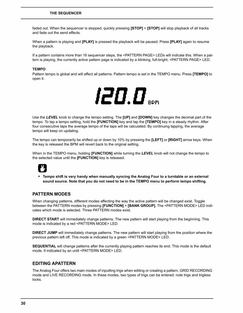
THE SEQUENCER
30
faded out. When the sequencer is stopped, quickly pressing [STOP] + [STOP] will stop playback of all tracks and fade out the send effects.
When a pattern is playing and [PLAY] is pressed the playback will be paused. Press [PLAY] again to resume the playback.
If a pattern contains more than 16 sequencer steps, the <PATTERN PAGE> LEDs will indicate this. When a pat-tern is playing, the currently active pattern page is indicated by a blinking, full-bright, <PATTERN PAGE> LED.
TEMPOPattern tempo is global and will affect all patterns. Pattern tempo is set in the TEMPO menu. Press [TEMPO] to open it.
Use the LEVEL knob to change the tempo setting. The [UP] and [DOWN] key changes the decimal part of the tempo. To tap a tempo setting, hold the [FUNCTION] key and tap the [TEMPO] key in a steady rhythm. After four consecutive taps the average tempo of the taps will be calculated. By continuing tapping, the average tempo will keep on updating.
The tempo can temporarily be shifted up or down by 10% by pressing the [LEFT] or [RIGHT] arrow keys. When the key is released the BPM will revert back to the original setting.
When in the TEMPO menu, holding [FUNCTION] while turning the LEVEL knob will not change the tempo to the selected value until the [FUNCTION] key is released.
• Tempo shift is very handy when manually syncing the Analog Four to a turntable or an external sound source. Note that you do not need to be in the TEMPO menu to perform tempo shifting.
PATTERN MODESWhen changing patterns, different modes affecting the way the active pattern will be changed exist. Toggle between the PATTERN modes by pressing [FUNCTION] + [BANK GROUP]. The <PATTERN MODE> LED indi-cates which mode is selected. Three PATTERN modes exist.
DIRECT START will immediately change patterns. The new pattern will start playing from the beginning. This mode is indicated by a red <PATTERN MODE> LED.
DIRECT JUMP will immediately change patterns. The new pattern will start playing from the position where the previous pattern left off. This mode is indicated by a green <PATTERN MODE> LED.
SEQUENTIAL will change patterns after the currently playing pattern reaches its end. This mode is the default mode. It indicated by an unlit <PATTERN MODE> LED.
EDITING APATTERNThe Analog Four offers two main modes of inputting trigs when editing or creating a pattern, GRID RECORDING mode and LIVE RECORDING mode. In these modes, two types of trigs can be entered: note trigs and trigless locks.

THE SEQUENCER
31
TRIG TYPESTwo types of trigs exist, note trigs and trigless locks. Note trigs trig notes while trigless locks can be used to apply parameter locks without trigging notes. Note trigs are indicated by full-bright <TRIG> LEDs and trigless locks are indicated by half-bright <TRIG> LEDs. Read more about parameter locks in section “PARAMETER LOCKS” on page 38. The two types of trigs are entered differently depending on whether GRID or LIVE record-ing mode is active.
GRID RECORDING MODEGRID RECORDING is a method of composing where trigs are added by using the [TRIG] keys.
Enter GRID RECORDING mode by pressing the [REC] key. A lit red <REC> LED indicates GRID RECORDING mode is active. Select the track to which you want to add trigs by pressing the relevant [TRACK] button. Place note trigs on the sequencer by pressing the [TRIG] keys. To add note values to trigs of the synth tracks, press and hold a [TRIG] key while pressing a [KEYBOARD] key. To add a trigless lock, press [FUNCTION] and [TRIG]. Add micro timing to a note trig by pressing and holding the [TRIG] key while pressing [LEFT] or [RIGHT]. A micro timing pop up menu will appear, showing the note offset.
If the pattern contains more than 16 steps, switch to the pattern page you want to edit by pressing the [PAGE] key. The active pattern page is being indicated by a fully lit <PATTERN PAGE> LED.
Press [PLAY] to listen to the sequence.
• All trigs of a track can be shifted forwards or backwards on the sequencer. While in GRID RECORDING mode, hold down [FUNCTION] while pressing the [LEFT] or [RIGHT] arrow keys to perform the trig shift.
• Preview a note trig, complete with its parameter locks, by pressing [TRIG] + a [KEYBOARD] key.
LIVE RECORDING MODELIVE RECORDING mode is the second method of adding trigs to the tracks. In this recording mode, the [KEY-BOARD] keys, or an external MIDI keyboard connected to the Analog Four, can be played in real time to input trigs to the tracks. It is also possible to enter parameter locks in real time. Trigs input in LIVE RECORDING mode will be placed on the sequencer in a micro timed fashion, meaning the µTM parameter in the NOTES SETUP menu will be locked accordingly to more accurately reflect the input timing of the trigs. This makes LIVE RECORDING mode record note inputs in a more expressive and un-quantized way. Micro timed trigs can be quantized, which is done in the NOTES SETUP menu. Read more about the µTM parameter on page 34. Quan-tizing is covered on page 35.
Hold [RECORD] and press [PLAY] to enter LIVE RECORDING mode. The sequencer will start to play and the <RECORD> LED will start to flash. You can now enter trigs to the active track in real time by pressing the keys on the KEYBOARD. For the synth and CV tracks, note values according to the KEYBOARD key presses will be recorded. In order to activate quantization of the LIVE RECORDING, do as above but double-press [PLAY].
To real time erase all trigs from a track, press and hold [TRACK] + [NO/RELOAD]. All trigs hit by the running LED of the sequencer will be erased from the active track. The trigs of more than one track can be removed by pressing several [TRACK] keys simultaneously.
To stop both the recording and the playback of the sequencer, press [STOP]. To exit LIVE RECORDING mode while keeping the sequencer playing, press [PLAY]. If LIVE RECORDING mode is active and [REC] is pressed, GRID RECORDING mode will be entered.

THE SEQUENCER
32
TRACK MENUIn this menu settings and options related to the active track are found. Open the menu by pressing [FUNCTION] + [KEYBOARD E1]. Navigate in the list using the [UP]/[DOWN] arrow keys or the LEVEL knob. Select options by pressing [YES]. Change the track that the menu will affect by pressing the [TRACK] keys.
NOTES SETUP contains settings mainly relating to track quantization and scale. It is the same menu as accessed by pressing [FUNCTION] + [NOTE]. The NOTES SETUP menu is covered in section “NOTES SETUP” on page 35.
ARP SETUP contains settings for the track arpeggiators. It is the same menu as accessed by pressing [FUNCTION] + [ARP]. The ARPEGGIATOR SETUP menu is covered on page 34.
RELOAD TRACK will reload the active track. Since tracks are a part of patterns which are automatically saved, it will either be reloaded to its original auto-saved state or to a specific saved state which can be determined by utilizing the SAVE TRACK command. Press [NO/RELOAD] + [KEYBOARD E1] for a short cut to the RELOAD TRACK command.
SAVE TRACK will save changes made to the active track. This is a special feature available in addition to the general, automatic, saving of patterns which occurs when patterns are changed. The feature is useful in situations where an individual track is being worked on, the results are favorable and you want to keep on working with the track while having the ability to revert it to a specific saved state. The SAVE TRACK command makes this possible. When reloading the track, it will not be reloaded to its original, pattern auto-saved, state, but to the manually saved state. Press [YES/SAVE] + [KEYBOARD E1] for a short cut to the SAVE TRACK command.
PATTERN MENUIn the PATTERN menu patterns can be saved and reloaded. Open the menu by pressing [FUNCTION] + [KEY-BOARD F1]. Select between the available commands by using the [UP]/[DOWN] arrow keys. Confirm selec-tions with [YES/SAVE].
RELOAD PATTERN will reload the active pattern. It will either be reloaded to its original auto-saved state or to a specific saved state which can be determined by utilizing the SAVE PAT-TERN command. Press [NO/RELOAD] + [KEYBOARD F1] for a short cut to the RELOAD PATTERN command.
SAVE PATTERN will save changes made to the active pattern. This is a special feature avail-able in addition to the general, automatic, saving of patterns which occurs when patterns are changed. The feature is useful in situations where a pattern is being worked on, the results are favorable and you want to keep on working with the pattern while having the ability to revert to a specific saved state. The SAVE PATTERN command makes this possible. When reloading the pattern, it will not be reloaded to its original, auto-saved, state, but to the manually saved

THE SEQUENCER
33
state. Press [YES/SAVE] + [KEYBOARD F1] for a short cut to the SAVE PATTERN com-mand.
• The RELOAD PATTERN command is great when improvising live. Any changes made to the active pattern, like adding bass line notes or similar, can immediately be undone.
ARPEGGIATORThe ARPEGGIATOR menu controls the six arpeggiators, one for each track. Arpeggiator settings are a part of the pattern, they are not stored together with kits. Select the track whose arpeggiator will be edited by pressing the relevant [TRACK] key. Open the ARPEGGIATOR menu by pressing [ARP].
MOD activates the arpeggiator and controls how the arpeggiated notes will be sorted.
• OFF will deactivate the arpeggiator.
• TRU will play the notes in the same order as they were inserted.
• UP will play the notes in an ascending order, from the lowest note to the highest, on a per octave basis.
• DWN will play the notes in a descending order, from the highest note to the lowest, on a per octave basis.
• CYC will play the notes first in an ascending order, then in an descending order.
• SHF will play the notes randomly on an octave range basis. If the arpeggio for exam-ple has a RNG setting of 2, the notes of the first octave range will be played randomly and once all notes have been played, all the notes of the second octave will be played in a new random order.
• RND will randomize the playback of the arpeggiated notes.
• PLY will arpeggiate a complete chord (POLYPHONY must be activated, see page 19) in the same way an individual note is arpeggiated in TRU mode.
SPD sets the speed of the arpeggiator. It is synchronized to the BPM of the project. A setting of 6 equals 16th notes, a setting of 12 equals 8th notes and so on.
RNG sets the octave range of the arpeggiator. After each finished arpeggiator cycle the arpeg-giated notes will be transposed one octave up. When the notes has reached the octave offset specified by the RNG setting the notes will be reset to their inital values. From there the octave transpose will be started all over again.
LEG controls the legato of the arpeggiator. This setting will affect the note trigs of the track even if the MOD setting is set to OFF.

THE SEQUENCER
34
• ON will play overlapping notes legato, releasing the old note after the new one. The NLEN setting adjusts the length of the notes when the arpeggiator is activated. If not activated the LEN setting will adjust the length of the notes.
• OFF will send out a MIDI note off message before the start of each arpeggiated note.
LEN controls the length of the arpeggiated notes.
NO2-NO4 selects the offset in semi-tones for three additional arpeggio notes. The offset is made from the original note trig. The TRK KEY SCALE and TRK KEY NOTE settings found in the NOTES SETUP menu will affect the note values of the arpeggiated notes.
• Please note only the NO2-NO4 parameters can be parameter locked.
ARPEGGIATOR SETUPPressing [FUNCTION] + [ARP] opens the ARPEGGIATOR SETUP menu. Here the arpeggiator length and note offsets are set.
Select the length of the arpeggio by turning DATA ENTRY knob E. The max length is 16 sequencer steps. The <TRIG LEDS> indicate the length of the arpeggio and, when the arpeggio is playing, the number of played arpeggio notes.
Arpeggio note offsets can be inserted by pressing a [TRIG] key and turning DATA ENTRY knob J. By pressing several [TRIG] keys simultaneously it is possible to adjust the note offsets of more than one step.
NOTE MENUThe NOTE menu controls general note settings for the active track. Open by pressing [NOTE]. NOTE menu set-tings are a part of the pattern, they are not stored together with kits.
The parameter settings seen in the NOTE menu settings are the default settings when placing trigs on the sequencer. Entering three note trigs, changing for example the note length parameter and then entering three more note trigs will thus make the last three note trigs share a different note length compared to the first three. To add individual settings per note, utilize parameter locks. Read more about this feature “PARAMETER LOCKS” on page 38. µTM, ENV, and LFO settings can only be changed when parameter locked.
NOT is the default note value.
VEL sets the velocity value. The higher the value, the higher the volume of the note. The default value is 100. Please note that this value will affect any VELOCITY MOD menu assign-ments. This menu is covered on page 26.
LEN sets the note length.

THE SEQUENCER
35
µTM controls the micro timing offset. A negative value will nudge the trig to a position before the quantized sequencer step, a positive after. Each micro timing value step is equal to one 1/384th of a note. When entering note trigs in the LIVE RECORDING mode, they will automati-cally be micro timed. Read more about this recording mode on page 31.
ENV controls whether the ENVF should be retrigged or not when a note trig or trigless lock is activated by the sequencer.
ENV controls whether the ENV2 should be retrigged or not when a note trig or trigless lock is activated by the sequencer.
LFO controls whether the LFO1 should be retrigged or not when a note trig or trigless lock is activated by the sequencer.
LFO controls whether the LFO2 should be retrigged or not when a note trig or trigless lock is activated by the sequencer.
• It is possible to real time record and real time erase NOT, VEL and LEN parameters. This is useful when for example inputting notes using an external MIDI keyboard sending MIDI velocity data. The same applies when entering notes using the mini-keyboard. In this case VEL changes will not be recorded though, as the mini-keyboard is not velocity sensitive. Read more about real time param-eter lock record and erase on page 38.
• When real time erasing all locks by pressing [FUNCTION]+[NO/RELOAD], note parameters are not included.
NOTES SETUPIn the NOTES SETUP menu, more settings relating to notes of the active track are found. Access the menu by pressing [FUNCTION] + [NOTE]. Navigate in the menu using the [UP]/[DOWN] arrow keys or the LEVEL knob. Change settings with the [LEFT]/[RIGHT] arrow keys.
GLOBAL QUANTIZE will affect all micro timed trigs of all tracks. The higher the quantize value, the more all micro timed trigs will be quantized.
TRK QUANTIZE will affect all micro timed trigs of the active track. The higher the quantize value, the more all micro timed trigs will be quantized.
TRK KEY SCALE sets the key scale of the track. All notes on the sequencer track will be auto-adjusted to the selected scale. The setting is non-destructive, meaning if the setting is changed from for example MIN to OFF, the notes will start playing according to their original note values. This setting also affects how the track will be transposed when performing a transpose function. If for example MAJ is set, all notes of the track will be transposed accord-ing to a major scale. Read more about the transpose functionality on page 40.
TRK KEY NOTE sets the key note of the track. This setting affects how the track will be trans-posed when performing a transpose function. The transpose will be an offset from the key note.
TRK TRANSPOSABLE will when activated make the track transposable. If deactivated, the track can not be transposed, which can be a relevant setting for tracks containing drum

THE SEQUENCER
36
sounds. A quick command for this setting exists. Press [TRANSPOSE] + [TRACK] to acti-vate/deactivate the transpose functionality for a track. Read more about track transpose on page 40.
CLICK TRACKThe CLICK TRACK menu controls the internal metronome of the Analog Four. Open the menu by pressing [FUNCTION] + [KEYBOARD A1]. Use the [UP]/[DOWN] arrow keys or the LEVEL knob to select in the list of settings. Press [LEFT]/[RIGHT] to change the highlighted setting.
ACTIVE activates/deactivates the metronome. It is also possible to press [FUNCTION] and double-pressing [KEYBOARD A1] to toggle the metronome on or off.
TIME SIG. NUM controls the note measure of the metronome time signature.
TIME SIG. DENOM controls the beat measure of the metronome time signature.
PREROLL controls for how many bars the metronome will sound before the sequencer starts playing. This setting is only relevant when LIVE RECORDING mode is initiated.
VOLUME controls the volume of the click.
SCALE MENUHere the general length and timing of the active pattern is set. Two modes exist in the SCALE menu. In NOR-MAL mode all tracks share the same length. In ADVANCED mode each track can have different lengths. Access the SCALE SETUP menu by pressing [FUNCTION] + [PAGE]. Use the [LEFT] and [RIGHT] arrow keys to select between the available settings. Use the [UP] and [DOWN] keys to adjust the different settings and to select between the two modes. The LEVEL knob can be used to adjust settings as well.
NORMAL MODEThis is the default mode. In this mode all tracks of the pattern share the same length and time signature. This screen will appear when the NORMAL setting is active.
The first two settings control the step length of the pattern. The leftmost number selects the number of steps in the pattern. The maximum number of steps available to the pattern is determined by the total length, set by the parameter to the right. This can be either 16, 32, 48 or 64 steps. If 17 steps or more are used in a pattern, the [PAGE] key is, while in GRID RECORDING mode, used to toggle between the different pattern pages.
The rightmost parameter controls the time signature of the pattern. It offers seven possible settings, 1/8X, 1/4X, 1/2X, 3/4X, 1X, 3/2X and 2X. A setting of 1/8X will play back the pattern at one eighth of the set tempo. 3/4X plays the pattern back at three quarters of the tempo. 3/2X will play back the pattern twice as fast as the 3/4X setting. 2X will make the pattern play at twice the BPM.

THE SEQUENCER
37
• Trigs are automatically copied when extending the length of a pattern. If a pattern consists of for example two pages and the pattern length is increased to four pages, the two added pattern pages will be copies of the first two pattern pages.
• Press the [PAGE] key for quickly changing the total length of the pattern. Press the [TRIG] keys to quickly change the number of steps of the pattern.
• A 2X time signature setting is useful for increasing the base resolution of the step sequencer to 32nd notes. A 3/4X setting is useful when the Analog Four is playing alongside other instruments set to the same BPM and you want the Analog Four to play triplets.
ADVANCED MODEIn this mode the tracks of the pattern can be assigned individual lengths. Select ADVANCED mode by navigat-ing to the SCALE column using the [LEFT] arrow key. Select ADVANCED by using the [DOWN] arrow key. In ADVANCED mode, two columns exist, TRACK and MASTER.
The TRACK column sets the step length of the track. It works just like setting the pattern length in NORMAL mode. The settings will only affect the active track. Press the [TRACK] keys to select the track whose scale set-tings will be edited.
The MASTER column is only available in ADVANCED mode. Here the master length, the master change length and the general time signature of the pattern are set.
LEN controls the amount of steps the pattern will play before all tracks are restarted. An INF setting will make the tracks of the pattern loop infinitely, without ever being restarted. Note that this setting also affects for how long the active pattern will play before a chained pattern will start playing. This can be overridden by the CHNG parameter.
CHNG controls for how long the active pattern will play before a cued or chained pattern will begin to play. This setting is important when for example LEN is set to INF. If no CHNG setting is made, the pattern will play infinitely and the next pattern will thus not be cued. But if CHNG for instance is set to 64, the pattern will behave like a pattern consisting of 64 steps in terms of cuing and chaining.
MASTER SCALE is the rightmost setting. It sets the general time signature of the pattern.
• If INF is selected the active pattern will play infinitely, making it impossible to change to another pattern.
• Press [FUNCTION] + [UP]/[DOWN] to set the MASTER LENGTH in increments of 16.
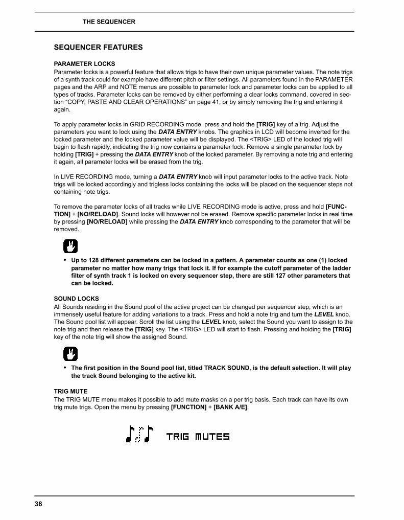
THE SEQUENCER
38
SEQUENCER FEATURES
PARAMETER LOCKSParameter locks is a powerful feature that allows trigs to have their own unique parameter values. The note trigs of a synth track could for example have different pitch or filter settings. All parameters found in the PARAMETER pages and the ARP and NOTE menus are possible to parameter lock and parameter locks can be applied to all types of tracks. Parameter locks can be removed by either performing a clear locks command, covered in sec-tion “COPY, PASTE AND CLEAR OPERATIONS” on page 41, or by simply removing the trig and entering it again.
To apply parameter locks in GRID RECORDING mode, press and hold the [TRIG] key of a trig. Adjust the parameters you want to lock using the DATA ENTRY knobs. The graphics in LCD will become inverted for the locked parameter and the locked parameter value will be displayed. The <TRIG> LED of the locked trig will begin to flash rapidly, indicating the trig now contains a parameter lock. Remove a single parameter lock by holding [TRIG] + pressing the DATA ENTRY knob of the locked parameter. By removing a note trig and entering it again, all parameter locks will be erased from the trig.
In LIVE RECORDING mode, turning a DATA ENTRY knob will input parameter locks to the active track. Note trigs will be locked accordingly and trigless locks containing the locks will be placed on the sequencer steps not containing note trigs.
To remove the parameter locks of all tracks while LIVE RECORDING mode is active, press and hold [FUNC-TION] + [NO/RELOAD]. Sound locks will however not be erased. Remove specific parameter locks in real time by pressing [NO/RELOAD] while pressing the DATA ENTRY knob corresponding to the parameter that will be removed.
• Up to 128 different parameters can be locked in a pattern. A parameter counts as one (1) locked parameter no matter how many trigs that lock it. If for example the cutoff parameter of the ladder filter of synth track 1 is locked on every sequencer step, there are still 127 other parameters that can be locked.
SOUND LOCKSAll Sounds residing in the Sound pool of the active project can be changed per sequencer step, which is an immensely useful feature for adding variations to a track. Press and hold a note trig and turn the LEVEL knob. The Sound pool list will appear. Scroll the list using the LEVEL knob, select the Sound you want to assign to the note trig and then release the [TRIG] key. The <TRIG> LED will start to flash. Pressing and holding the [TRIG] key of the note trig will show the assigned Sound.
• The first position in the Sound pool list, titled TRACK SOUND, is the default selection. It will play the track Sound belonging to the active kit.
TRIG MUTEThe TRIG MUTE menu makes it possible to add mute masks on a per trig basis. Each track can have its own trig mute trigs. Open the menu by pressing [FUNCTION] + [BANK A/E].

THE SEQUENCER
39
Select the track to which you want to add trig mute trigs by pressing the corresponding [TRACK] key. While in the TRIG MUTE menu, entered trigs will mute any trigs placed of the active track, given the trigs are located on the same sequencer steps.
• Trig mutes can be quickly added to note trigs or trigless locks. Keep the note trig or trigless lock pressed and press [BANK A/E]. A trig mute trig will automatically be placed on the same sequencer step as the note trig/trigless lock.
• Press a note trig/trigless lock to quickly see if a trig mute trig is placed on the same sequencer step as the trig. If that is the case, the <BANK A/E> LED will light up.
• Trig mutes are good for experimenting with the feel of tracks when playing live. The last eight steps of a bass line track could for example be muted to build suspense.
ACCENTAdding accent trigs is useful for quickly changing the volume and filter envelope behavior, or accentuation, for chosen steps of a track. Accent level is also a modulation destination, meaning it can be affected by for example LFOs. Open the ACCENT menu by pressing [FUNCTION] + [BANK B/F].
Select the track that will be affected by pressing the corresponding [TRACK] key. Select the accent value by turning the LEVEL knob. The higher the value, the more accentuation will be added to accent trigs.
While the ACCENT menu is open, the sequencer will display accent trigs. Place or remove accent trigs by pressing the [TRIG] keys. If an accent trig is placed on the same sequencer step as a note trig, the note trig will be accentuated.
• A note trig can be quickly accented. Keep the note trig pressed and press [BANK B/F]. An accent trig will automatically be placed on the same sequencer step as the note trig.
• Press a note trig/trigless lock to quickly see if an accent trig is placed on the same sequencer step as the trig. If that is the case, the <BANK B/F> LED will light up.
NOTE SLIDEThe NOTE SLIDE menu makes it possible for the pitch of two separate note trigs to slide between each other. Open the menu by pressing [FUNCTION] + [BANK C/G]. When this menu is active and [TRIG] keys are pressed, note slide trigs will be placed on the sequencer.
If a note slide trig is placed on the same step as a note trig, the pitch of the previous note trig will slide. For instance, if a track contains two note trigs and a note slide trig is placed on the same step as the second note trig, the pitch of the first note trig will slide to the pitch of the second note trig. The speed of the pitch slide is determined by the SLI parameter, found in the second page of the OSC2 menu. Read more about this parame-ter in “Appendix A: SYNTH TRACK PARAMETERS“.

THE SEQUENCER
40
• Note slides can be quickly added to note trigs. Keep the note trig pressed and press [BANK C/G]. A note slide trig will automatically be placed on the same sequencer step as the note trig.
• Press a note trig lock to quickly see if a note slide trig is placed on the same sequencer step as the trig. If that is the case, the <BANK C/G> LED will light up.
PARAMETER SLIDEThe PARAMETER SLIDE menu makes it possible for the parameter values of two separate note trigs or trigless locks of a track to slide between each other. Open the menu by pressing [FUNCTION] + [BANK D/H]. When this menu is active and [TRIG] keys are pressed, slide trigs will be placed on the sequencer.
For a parameter value to slide between two trigs, it needs to be locked on one of the trigs. A locked parameter value will slide to the unlocked value and vice versa. To make the parameter value slide, place a slide trig on the same sequencer step as the trig whose parameters you want to slide. The speed of the slide is relative to the current tempo and the slide is completed when the next trig is reached. Several parameter values can slide at the same time.
• Parameter slides can be quickly added to note trigs or trigless locks. Keep the note trig or trigless lock pressed and press [BANK D/H]. A parameter slide trig will automatically be placed on the same sequencer step as the note trig/trigless lock.
• Press a note trig/trigless lock to quickly see if a parameter slide trig is placed on the same sequencer step as the trig. If that is the case, the <BANK D/H> LED will light up.
SWINGSets the swing of the pattern, allowing for a different rhythmic groove. Access this menu by pressing [FUNC-TION] + [KEYBOARD B1].
TRACK TRANSPOSETracks can be transposed up or down and the transpose function can be locked for one handed operation. The tracks that will be affected by the transpose functionality are set in the NOTES SETUP menu. Read more in sec-tion “NOTES SETUP” on page 35. A quick command for this also exists. Press [TRANSPOSE] + [TRACK] to activate or deactivate the transpose functionality for the tracks. When pressing and holding the [TRANSPOSE] key, lit <TRACK> LEDs indicate which tracks are transpose activated.
To transpose, press and hold [TRANSPOSE] and press a [KEYBOARD] key. Select a different octave range to transpose to by pressing [UP] or [DOWN]. After having performed a transpose, a little pop-up window will show how many semitones the transpose consists of.
The notes of the tracks are transposed according the TRK KEY NOTE and TRK KEY SCALE settings, found in the NOTES SETUP menu covered on page 35. The transpose is an offset to the set key note, meaning all note

THE SEQUENCER
41
trigs retain their original note values after having been transposed. If for example the key note is set to a C and [KEYBOARD F1] is pressed, the transpose activated tracks will be transposed +5 semitones.
The transpose offset can be applied permanently as well. After performing a transpose, press [TRANSPOSE] + [YES/SAVE]. The value of the transposed note trigs will be permanently altered.
If [FUNCTION] + [TRANSPOSE] are pressed, the transpose lock functionality will be activated. Transpose lock is indicated by a full-bright <TRANSPOSE> LED. When this function is activated, the [TRANSPOSE] key will act as if constantly pressed, enabling one-handed transpositions when pressing the [KEYBOARD] keys.
• Please note that when transpose lock is activated, the [KEYBOARD] keys will not be able to play Sounds or set the note value of note trigs. They will only be used for transpose duties. The sec-ondary functions of the [KEYBOARD] keys, for instance accessing the KIT and SOUND menus, are still possible to access.
DESTRUCTIVE TRANSPOSETracks can be transposed destructively, altering the note values of the note trigs permanently. Do so by pressing [TRACK] + [UP]/[DOWN]. The value of the note trigs will be changed up or down in the selected amount of semitones. The tracks do not have to be transpose activated for this to work.
COPY, PASTE AND CLEAR OPERATIONSPatterns, track pages, tracks and trigs can be copied, pasted and cleared.
The active pattern can be copied to either another location in the same bank or to a location in another bank. To perform a pattern copy operation, GRID RECORDING mode must not be active. Copy the pattern by pressing [FUNCTION] + [REC]. Select another pattern and paste the copied pattern to this location by pressing [FUNC-TION] + [STOP]. The operation can be undone by pressing [FUNCTION] + [STOP] again. Clear a pattern by pressing [FUNCTION] + [PLAY]. Undo the operation by repeating the button presses.
After having selected a pattern, and before releasing any key, [REC], [PLAY] and [STOP] can be pressed to copy, clear or paste patterns. No new chain will be built, nor any pattern enqueued. It is possible to clear, copy or paste multiple patterns at the same time.
Individual tracks can be copied, pasted and cleared in the same way as patterns. To do so, GRID RECORDING mode needs to be active.
A track page is one of the up to four pages of sequencer steps a pattern can consist of. It is similar to copy/paste/clear a track, but will only affect the active track page. GRID RECORDING mode needs to be active here as well. Select the track page that will be affected by pressing the [PAGE] key. Copy by pressing [PAGE] + [REC]. Select a new track page and press [PAGE] + [STOP] to paste. Undo by pressing [PAGE] + [STOP] again. Press [PAGE] + [PLAY] to clear the active track page. Undo the operation by repeating the button presses.
Copy the Sound of a synth track by pressing [TRACK] + [REC]. Select a new track to which the Sound will be pasted and press [TRACK] + [STOP] to paste.
Trigs, complete with all parameter lock settings, can be copied, pasted and cleared as well. GRID RECORDING mode needs to be active to access this functionality. Press and hold a trig and press [REC] to perform the copy operation. Paste by holding another [TRIG] key and pressing [STOP]. It is also possible to copy more than one trig. Hold several trigs and press [REC]. The trig first pressed will act as the starting point. When pasting, the other copied trigs will be placed in relation to this trig. Paste the copied sequence of trigs by holding another [TRIG] key and pressing [STOP]. Clear trig locks by holding one or more trigs and press [PLAY].
QUICK SAVE AND RELOAD COMMANDSKits, Sounds, tracks, patterns and songs can instantly be saved and reloaded. When reloading, settings will revert to their saved state.
THE SEQUENCER
42
To quick save a kit, press [YES/SAVE] + [KEYBOARD C1]. This command is the same as the SAVE KIT com-mand found in the KIT menu, covered on page 16.
To quick save the track Sound of the active track, press [YES/SAVE] + [KEYBOARD D1]. This command is the same as the STORE TRACK SOUND command found in the SOUND MANAGER menu, covered on page 24.
To quick save a track, press [YES/SAVE] + [KEYBOARD E1]. The operation is the same as the SAVE TRACK command, covered on page 42.
To quick save the active pattern, press [YES/SAVE] + [KEYBOARD F1]. The operation is the same as the SAVE PATTERN command, covered on page 32.
To quick save a song, press [YES/SAVE] + [KEYBOARD G1]. The command is the same as the SAVE com-mand found in the SONG menu, covered on page 45.
To quick reload a kit, press [NO/RELOAD] + [KEYBOARD C1]. This command is the same as the RELOAD KIT command found in the KIT menu, covered on page 16.
To quick reload the track Sound of the active track, press [NO/RELOAD] + [KEYBOARD D1].
To quick reload a track, press [NO/RELOAD] + [KEYBOARD E1]. The operation is the same as the RELOAD TRACK command, covered on page 42.
To quick reload the active pattern, press [NO/RELOAD] + [KEYBOARD F1]. The operation is the same as the RELOAD PATTERN command, covered on page 32.
To quick reload a song, press [NO/RELOAD] + [KEYBOARD G1]. The command is the same as the RELOAD command found in the SONG menu, covered on page 45.

CHAINS AND SONGS
43
CHAINS AND SONGSChains are sequences consisting of several patterns. Chains and patterns can be used to form songs.
256 pattern entries are available for the 64 chains. One chain, for example, can be made of 256 patterns or two chains can be made of 128 patterns each. In most scenarios, using 2-8 patterns per chain is sufficient.
One song is always active and being worked on. Songs contain two main forms of entries, song rows and a scratch pad row. The active song row is visible on the graphics located in the lower left part of the LCD. If a scratch pad row is active, the graphics will show “_ _:”.
Each song row contains a chain or a pattern. These entries are saved together with the song. The scratch pad row also contains a chain or a pattern and is also saved as a part of the song. The intended use of the scratch pad row is for quickly experimenting with chains and patterns without affecting already programmed song rows.
CHAINSIf the active song row or scratch pad row contains a chain, all patterns of the chain will be played when activating the CHAIN mode by pressing [CHAIN MODE]. When deactivating the mode, and SONG mode is not active, the currently active pattern will be played over and over. The currently active pattern, and any other patterns in the chain, are visible in the lower left corner of the LCD screen. The active pattern is shown with inverted color.
Chains can be created even if CHAIN mode is deactivated. When creating chains this way, two methods exist: detailed chain mode and quick chain mode. Create chains according to detailed mode by pressing [CHAIN MODE] + [LEFT]/[RIGHT] to move the chain cursor. It can either be placed before a pattern, on a pattern, or after a pattern. If the cursor is placed before a pattern and a new pattern is selected by pressing [BANK X/X] + [TRIG], the selected pattern will be inserted before the pattern located after the cursor. If the cursor is highlight-ing a pattern and a new pattern is selected, the highlighted pattern will be replaced. When activating CHAIN mode, the patterns in the chain will be played in sequence. The chain will be looped once the final pattern of the chain has played.
To create chains in quick mode, press and hold [BANK X/X] and then press the [TRIG] key for the pattern you want the chain to start with. As long as you keep the first [TRIG] key pressed, subsequent [TRIG] keys pressed will add patterns to the chain. In quick mode, it is only possible to chain patterns from the same bank. Please note that the previous chain will be erased when using quick mode. PATTERN mode must be set to SEQUEN-TIAL if you wish to create chains in quick mode.
Pressing [CHAIN MODE] + [NO/RELOAD] will, depending on the location of the chain cursor, either erase the pattern located before the cursor or the one highlighted by it.
Pressing [CHAIN MODE] + [PLAY] will clear the chain.
Pressing [FUNCTION] + [CHAIN MODE] will create a new, blank, scratch pad row “_ _:”. The new scratch pad row will be moved down one step in the song row list, which can be seen when opening the SONG EDIT menu. The content of the previous scratch pad row will be added as a new song row. The position of the scratch pad row determines where the new song row is placed. See SONG EDIT MENU on how to relocate song rows (including the scratch pad row) within the song.
• CHAIN mode is ideal when improvising live. When CHAIN mode is deactivated and only the cur-rently active pattern is looping, create a chain and then activate CHAIN mode. At any time, exit CHAIN mode to loop one pattern only. Add and remove patterns to create a completely new chain and activate CHAIN mode again. By creating new chains through pressing [FUNCTION] + [CHAIN MODE], improvised songs can quickly be created.

CHAINS AND SONGS
44
SONGSSongs are essentially patterns and chains structured to form a long sequence. To enter SONG mode, press the [SONG MODE] key. The <SONG> LED will light up, indicating SONG mode is active. The active song will start to play, row by row. If the active song row is the scratch pad row, song row 00 will be played afterwards, given that the song has been programmed in SONG EDIT and the scratch pad row has not been moved within the song. The currently playing song row is shown in the lower left corner of the LCD screen.
SONG EDIT MENU
Songs are created in the SONG EDIT menu, which is accessed by pressing [FUNCTION] + [SONG MODE].
Songs are played row by row, starting from the top and moving towards the bottom. If a song row contains a chain, all patterns in the chain will play before the song play position moves to the next row. The song play posi-tion is indicated by inverted pattern number graphics. In the top right corner of the LCD screen the BPM and the amount of played bars and beats is shown.
To navigate between song rows as well as patterns assigned to the song rows, use the [ARROW] keys. When the song cursor highlights a pattern position, the pattern number becomes enclosed by a square. When the song cursor is placed before or after a pattern, it will form a thin line.
To start playing a Song from the beginning, double-press [STOP]. The song play position will automatically be moved to the first pattern of the first song row, which normally is the scratch pad row. Songs can however start playing from any pattern position. Highlight a pattern position by moving the song cursor using the [ARROW] keys. Press [YES/SAVE] to select this position. The graphics will become inverted, indicating this is the song play position. Press [PLAY] to start playing the Song from this position.
• Copy, paste and clear commands can be executed on the song rows.
ADDING SONG ROWS AND ASSIGNING PATTERNS AND CHAINS
Press [FUNCTION] + [YES/SAVE] to add a song row. The new song row will be inserted below the row on which the cursor is, and the pattern A01 will automatically be assigned to the new row. To assign another pattern to the song row, use the [ARROW] keys to move the song cursor so the pattern assigned to the row becomes highlighted and then press a [BANK X/X] key + a [TRIG] key. In general, the pattern assigning procedure is the same as when selecting a pattern, covered in the section “SELECTING A PATTERN” on page 29.
To add a chain to a song row, select a song row and press the [RIGHT] arrow key. The song cursor will move from the pattern position and form a thin, standing line. Press a [BANK X/X] key + a [TRIG] key to select the pattern that will be added to the chain.
Remove a pattern in a chain by highlighting it with the song cursor and pressing [FUNCTION] + [NO/RELOAD].
If a song row contains a chain, individual patterns can be rearranged in the chain. Select the pattern by highlight-ing it with the song cursor and press [FUNCTION] + [LEFT]/[RIGHT].
Move a song row up or down in the song by moving the song cursor to the song row and pressing [FUNCTION] + [UP]/[DOWN]. Note that the scratch pad row “_ _:” can be moved up or down in the list in the same way. The position of the scratch pad row is important, because it determines where the new song row will be located, when a new chain (and a new scratch pad row) is created outside of the SONG EDIT menu. The new song row will be inserted above the new scratch pad row, and it will have the same number as the song row below the pre-vious scratch pad row.
Erase an entire song row, one pattern at a time, by repeatedly pressing [FUNCTION] + [NO/RELOAD].

CHAINS AND SONGS
45
ADDING REPEATS, MUTES AND TRANSPOSE INFORMATIONVarious extra information can be entered for song rows and pattern or patterns assigned to the song rows.
Repeat a song row with a chosen factor by moving to the leftmost position of the song row. Turn DATA ENTRY knob A to select how many times the song row will be repeated.
Add song mutes to a pattern by highlighting it and pressing [FUNCTION] + [TRACK]. The mute graphics to the right in the LCD screen shows which tracks have been muted. Tracks muted from a song are also indicated by half-bright <TRACK> LEDs. Unlike track mutes, song mutes are pattern specific. Different patterns can have dif-ferent song muted tracks. When not in SONG EDIT menu and song muted tracks are manually muted by press-ing [FUNCTION] + [TRACK], the <TRACK> LEDs will become unlit, i.e. track muted. The track mute method is covered on page 28. Adding song mutes when not in the SONG EDIT menu can also be achieved by pressing [SONG MODE] + [TRACK] or [CHAIN MODE] + [TRACK].
Transpose a pattern by highlighting it with the song cursor and pressing [TRANSPOSE] + the [KEYBOARD] keys. A song transpose works like a track transpose, albeit automated. The track transpose functionality is cov-ered on page 40.
SONG MENUIn the SONG menu, songs can be saved, loaded renamed et cetera. Access the menu by pressing [FUNCTION] + [KEYBOARD G1].
RELOAD will reload the active song. It will be restored to its saved version. Press [NO/RELOAD] + [KEYBOARD G1] for a short cut to this command.
LOAD will open a menu where saved songs can be loaded. The active song is indicated by inverted graphics.
SAVE will save the active song to one of the 16 song slots. The active song is indicated by inverted graphics. Press [YES/SAVE] + [KEYBOARD G1] for a short cut to this command.
CLEAR will clear the active song from all content.
EDIT will open the EDIT menu. It is the same menu as accessed by pressing [FUNCTION] + [SONG MODE]. See page 44 for more info about this menu.
RENAME will open a menu where the active song can be renamed.

GLOBAL MENU
46
GLOBAL MENU The GLOBAL menu offers settings that affect the Analog Four on a global level. Global tune, MIDI and CV set-tings are made here. Up to four Global slots, where each can have individual settings, are available.
Access the menu by pressing [FUNCTION] + [KEYBOARD C2]. Scroll the list by using [UP]/[DOWN] or the LEVEL knob. Open a highlighted menu by pressing [YES/SAVE].
PROJECTManage projects here. This menu is covered in the section “PROJECTS” on page 13.
GLOBAL SLOTSelects which of the four Global slots to use. Select the active slot by using the [LEFT]/[RIGHT] arrow keys. Press [YES/SAVE] to confirm the selection. All changes made to a Global slot are automatically saved. A slot stores the current configuration of the synth, sequencer, CV and MIDI settings. All changes made to a Global slot are automatically saved.
SYNTH MASTER TUNEThe Analog Four master tune settings are found here.
SYNTH MASTER TUNE Sets the master tune for the analog oscillators. The default setting is the international standard middle A, 440.0 Hz. The tuning across all octaves is done according to the 12-TET convention.
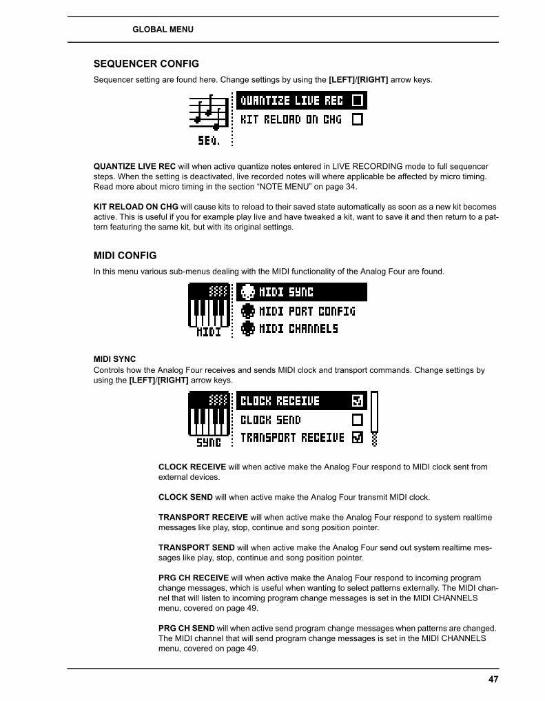
GLOBAL MENU
47
SEQUENCER CONFIGSequencer setting are found here. Change settings by using the [LEFT]/[RIGHT] arrow keys.
QUANTIZE LIVE REC will when active quantize notes entered in LIVE RECORDING mode to full sequencer steps. When the setting is deactivated, live recorded notes will where applicable be affected by micro timing. Read more about micro timing in the section “NOTE MENU” on page 34.
KIT RELOAD ON CHG will cause kits to reload to their saved state automatically as soon as a new kit becomes active. This is useful if you for example play live and have tweaked a kit, want to save it and then return to a pat-tern featuring the same kit, but with its original settings.
MIDI CONFIGIn this menu various sub-menus dealing with the MIDI functionality of the Analog Four are found.
MIDI SYNCControls how the Analog Four receives and sends MIDI clock and transport commands. Change settings by using the [LEFT]/[RIGHT] arrow keys.
CLOCK RECEIVE will when active make the Analog Four respond to MIDI clock sent from external devices.
CLOCK SEND will when active make the Analog Four transmit MIDI clock.
TRANSPORT RECEIVE will when active make the Analog Four respond to system realtime messages like play, stop, continue and song position pointer.
TRANSPORT SEND will when active make the Analog Four send out system realtime mes-sages like play, stop, continue and song position pointer.
PRG CH RECEIVE will when active make the Analog Four respond to incoming program change messages, which is useful when wanting to select patterns externally. The MIDI chan-nel that will listen to incoming program change messages is set in the MIDI CHANNELS menu, covered on page 49.
PRG CH SEND will when active send program change messages when patterns are changed. The MIDI channel that will send program change messages is set in the MIDI CHANNELS menu, covered on page 49.

GLOBAL MENU
48
MIDI PORT CONFIGMIDI port related settings are found in this menu. Change settings by using the [LEFT]/[RIGHT] arrow keys.
TURBO SPEED selects the multiplier of the MIDI transfer rate that will be used when the Analog Four MIDI IN/OUT ports are connected to the MIDI OUT/IN ports of a turbo protocol compatible device. The [LEFT]/[RIGHT] arrow keys are used to select the multiplier. If AUTO is chosen, press [YES/SAVE] to start the turbo speed negotiation.
OUT PORT FUNCTIONALITY selects what type of signal the MIDI OUT port will send.
• MIDI makes it possible for the port to send out MIDI data.
• DIN 24 will make the port send DIN 24 sync messages. No MIDI data can be sent when this option is selected.
• DIN 48 will make the port send DIN 48 sync messages. No MIDI data can be sent when this option is selected.
• On DIN 24/48 operation: When the [STOP] key is pressed twice quickly, the DIN sync outputs are put in a ready to start mode. In this mode, the synced unit will start directly when the sequencer starts. When in this mode, an external unit (for example a TB-303) cannot be programmed. Exit the ready to start mode by pressing [STOP] once.
THRU PORT FUNCTIONALITY selects what type of signal the MIDI THRU port will send. The avalible settings are the same as for OUT PORT FUNCTIONALITY above.
INPUT FROM selects the source the Analog Four will receive MIDI data from.
• DISABLED will make the Analog Four disregard any incoming MIDI data.
• MIDI will make the Analog Four listen only to MIDI data sent to the MIDI IN port.
• USB will make the Analog Four listen only to MIDI data sent to the USB port.
• MIDI+USB will make the Analog Four listen to MIDI data sent to both the MIDI IN and USB ports.
OUTPUT TO selects the destination to which the Analog Four will send MIDI data.
• DISABLED will stop the Analog Four from sending out any MIDI data.
• MIDI will make the Analog Four send MIDI data to the MIDI OUT port only.
• USB will make the Analog Four send MIDI data to the USB port only.
• MIDI+USB will make the Analog Four send MIDI data to both the MIDI OUT and USB ports.

GLOBAL MENU
49
• If MIDI+USB is selected in the INPUT FROM and/or OUTPUT TO settings, MIDI data transfers may limit the USB speed.
OUTPUT CH selects whether the mini-keyboard and the knobs will send data on the AUTO CHANNEL or the MIDI channel of the selected track.
PARAM OUTPUT selects what type of MIDI messages the DATA ENTRY knobs will send. For information about which CC/NRPN parameters that will be sent, please see “Appendix D: MIDI“.
• NRPN will make the knobs send out NRPN MIDI messages.
• CC will make the knobs send out CC MIDI messages.
ENCODER DEST controls whether the DATA ENTRY and LEVEL knobs will send MIDI data or not. When set to INT, no MIDI data will be sent. When set to INT + EXT, MIDI will be sent internally as well as externally.
KEYBOARD DEST controls whether the [KEYBOARD] keys will send MIDI note data or not. When set to INT, no MIDI data will be sent. When set to INT + EXT, MIDI will be sent internally as well as externally. When set to EXT, MIDI will only be sent externally.
MUTE DEST controls whether track mute/unmute will send MIDI CC/NRPN messages or not. When set to INT, no MIDI data will be sent. When set to INT + EXT, messages will be sent internally as well as externally. When set to EXT, messages will only be sent externally.
RECEIVE NOTES will when active make it possible to play the Analog Four using an external MIDI keyboard.
RECEIVE CC/NRPN will when active make it possible to control Analog Four parameters from an external MIDI device sending CC/NRPN data.
LIVE REC ON TRACK CHANNEL when the box is ticked, active LIVE RECORDING will record incoming MIDI notes on each of the specified track channels (see below). When unticked, LIVE RECORDING will not (but still record on the currently active track via the auto channel).
MIDI CHANNELSThis menu handles the MIDI channel configuration.
TRACK 1-4, FX, CV selects dedicated MIDI tracks that will control the synth, FX and CV tracks. An OFF setting will make the track disregard any incoming MIDI messages.
PERF CHANNEL selects the MIDI channel the knobs will send MIDI data on when PERFOR-MANCE mode is active.
AUTO CHANNEL selects the MIDI channel that will give access to the currently active track. If an external MIDI keyboard connected to the Analog Four sends MIDI data on this channel, the

GLOBAL MENU
50
keyboard will control the active track. This is useful when for example quickly changing between the active synth tracks to play different Sounds.
PROGRAM CHANGE IN CHANNEL selects the MIDI channel that will listen for incoming pro-gram change messages. An AUTO setting will use the AUTO channel. Enable the Analog Four to respond to program change messages in the MIDI SYNC menu, covered on page 47.
PROGRAM CHANGE OUT CHANNEL selects the MIDI channel that will send program change messages when changing patterns. An AUTO setting will use the AUTO channel. Enable the Analog Four to send program change messages in the MIDI SYNC menu, covered on page 47.
MULTI MAP EDITOpens an editor for mapping the functions of single notes or note ranges on an external MIDI keyboard. The functions that can be mapped include: Internal trigging of Sounds on any track, trigging of MIDI notes on any MIDI channel and the ability to trig patterns with custom transpose and timing settings. Multi map allows custom mapped keyboards splits, pattern trigging per key, Sound trig per key, MIDI trig of external synths, and more. In the Multi map mode, for example, full analog drum kits, bass lines, and lead sounds can be played simultane-ously. Ideal for performances and live improvisations.
Additionally, the internal multi map trigs can be recorded with the Analog Four sequencer. At most, one unique function may be mapped for each of the 128 keys of the entire MIDI keyboard range. One multi map setting is stored for each global slot, which means 4 different keyboard maps per project can be used..
ENTRIES are the basic building blocks of the multi map. They define what fuction will be assigned to each key or key range. Up to 128 entries may be created per multi map. If no entries exist, select ENTRIES, and then CREATE NEW ENTRY. If you wish to erase all entries to start anew, select ENTRIES and choose CLEAR ALL ENTRIES. If you wish to use the default multi map, a keyboard split, choose CREATE SPLIT. Select the entry to edit in the left part of the display by using the [UP]/[DOWN] arrow keys and press [YES/SAVE]. The cur-sor will move to the right part of the display where the list of mapping alternatives is visible.
To edit a multi map entry, navigate by using the [UP]/[DOWN] arrow keys. Change the high-lighted item in the list by pressing the [LEFT] or [RIGHT] arrow keys.
Note that the map entries may be instantly tried by playing the specified range on your exter-nal MIDI keyboard or on the Analog Four [KEYBOARD] keys.
• To use your custom multi map, remember to set the external MIDI keyboard to the assigned PERF CHANNEL (or change the performance channel in the MIDI CHANNEL menu to that of the MIDI keyboard)
FUNCTION selects one of the four main types of functionality for the MIDI mapping.

GLOBAL MENU
51
• INT.TRIG sets the chosen MIDI keyboard key or range to control specific Sounds from the Sound pool or the +Drive Sound library.
RANGE LOW sets the note on the keyboard on which to start the desired key-board range.
RANGE HIGH sets the note on the keyboard on which to end the desired key-board range. If a single key is to be mapped, set to the same note as RANGE LOW.
TRACK sets which track the selected keyboard range or key will play. AUTO will play the active track, while TRK 1, TRK 2, TRK 3, TRK 4, FX TRK and CV TRK sets the range to play the specific synth, FX or CV track of your choice.
NOTE sets which note the start of the chosen keyboard range will play. If no off-set is desired, it should be set to the same note as RANGE LOW.
NOTE INC defines by what increment the subsequent notes played will increase. For instance, if this value is set to 2, and the first note in the range is C5, the following note in the range will play D5, the one after that E5 and so on. If set to 0, all notes in the keyboard range will play the same note (as set in NOTE above). If a 1:1 correspondence is desired, set to 1.
SOUND SLOT sets which one of the 128 Sounds, found in the Sound pool of the active project, the keyboard range will play. If set to OFF, the track Sound of the chosen TRACK above will be played.
SOUND INC sets by what increment the next key in the chosen keyboard range will play the next sound slot Sound. If set to 0, the same Sound as defined above will be played across the whole defined range. If set to 1, it will play the next successive sound slot Sound for each successive key pressed. Setting the value to 2 will play every other Sound starting from the sound slot, setting it to 4 every fourth and so on.
• In MULTI MAP EDIT, Setting a specific SOUND SLOT and setting SOUND INC to 1 is convenient if you wish to define, for example, a succession of drum sounds that you have stored in a given sound slot range to be mapped to a certain section of the keyboard. Instant access to those snares, kicks and hihats!
FIXED VEL will, if set to OFF, make the velocity sensitivity of the MIDI keyboard work as usual. It may also be set to a constant specific value between 1 and 127, 1 being the lowest and 127 the highest possible velocity.
DELETE ENTRY deletes the whole entry. Select and confirm by pressing [YES/SAVE].
INSERT BEFORE will create a new entry with a range ending on the note preceding the current entry. Select by pressing [YES/SAVE].
INSERT AFTER will create a new entry with a range beginning on the note suc-ceeding the current entry. Select by pressing [YES/SAVE].
• EXT.TRIG allows MIDI control of external equipment for a chosen keyboard key or range.

GLOBAL MENU
52
CHANNEL sets which specific MIDI channel on which the MIDI note messages are to be sent, or AUTO.
NOTE sets which note the start of the chosen keyboard range will play.
NOTE INC defines by what increment the subsequent notes played will increase.
FIXED VEL will, if set to OFF, make the velocity sensitivity of the MIDI keyboard work as usual. It may also be set to a constant specific value between 1 and 127.
DELETE ENTRY deletes the whole entry. Select and reconfirm by pressing [YES/SAVE].
INSERT BEFORE will create a new entry with a range ending on the note preceding the current entry. Select by pressing [YES/SAVE].
INSERT AFTER will create a new entry with a range beginning on the note suc-ceeding the current entry. Select by pressing [YES/SAVE].
• NONE sets a keyboard key or range that will not be used for any function. Convenient for defining a ‘no-play’ zone on the keyboard between two or more sections with differ-ent Sounds or functions.
RANGE LOW sets the note on the keyboard on which to start the desired key-board range.
RANGE HIGH sets the note on the keyboard on which to end the desired key-board range.
DELETE ENTRY deletes the whole entry. Select and confirm by pressing [YES/SAVE].
INSERT BEFORE will create a new entry with a range ending on the note preceding the current entry. Select by pressing [YES/SAVE].
INSERT AFTER will create a new entry with a range beginning on the note suc-ceeding the current entry. Select by pressing [YES/SAVE].
• PAT.PLAY maps a chosen pattern to a specific MIDI keyboard key or range.
RANGE LOW sets the note on the keyboard on which to start the desired key-board range.
RANGE HIGH sets the note on the keyboard on which to end the desired key-board range.
PATTERN selects which pattern A01 - H16 of the active project will be played when pressing a keyboard key in the range specified above. Set to CUR if the current pattern is to be played.
PATTERN INC selects the increment with which the pattern will increase for each successive key press in the specified range. For example, if set to 1, each successive key will start pattern A01, A02, A03 and so on. Set to 2 it will play pattern A01, A03, A05 et cetera. Set to 0 if the same pattern as set in PATTERN above is to be played for every key in the range.

GLOBAL MENU
53
TRANSPOSE transposes the pattern up or down 1-36 octaves. No transpose if set to 0.
TRANSPOSE INC sets the increment by which the transpose will be increased for each step of the chosen keyboard range. No increase if set to 0.
CHG MODE sets the mode of starting the pattern. D.START starts the selected pattern directly from its first step. D.JUMP starts the selected pattern on the step following the current sequencer step. SEQ. starts the pattern from its first step once the current pattern has reached its final step.
DELETE ENTRY deletes the whole entry. Select and confirm by pressing [YES/SAVE].
INSERT BEFORE will create a new entry with a range ending on the note preceding the current entry. Select by pressing [YES/SAVE].
INSERT AFTER will create a new entry with a range beginning on the note suc-ceeding the current entry. Select by pressing [YES/SAVE].
CV CONFIGCV/Gate output signals are calibrated and set up in this menu.
CV A-D CONFIGEach of the subpages are identical and one for each CV/Gate output exists. The list of available parameters in this menu will depend on the menu settings. When the CV track is active, pressing [FUNCTION] + [CV A-D] is an alternate way of opening this menu for each corresponding CV/Gate output.
Please read the following paragraphs on how to set up CV pitch control. CV pitch is configured by finding the voltages generating two different notes from the synthesizer you wish to control. To get a good result you should select the notes two or three octaves apart.
Before configuring the pitch output you should setup a gate output so that notes can be triggered on the receiv-ing end. You should also set up the gate and pitch parameters so that they use the same source track for trigger-ing notes.
GLOBAL MENU
54
Select NOTE 1, it could for example be C3. Then highlight VOLTAGE 1 and press the [YES/SAVE] key. This will trigger a C3 note which is played for as long as you hold down the key. While keeping [YES/SAVE] pressed, adjust the voltage until the controlled synthesizer actually plays the note C3 using [ARROW] keys [LEFT]/[RIGHT] or DATA ENTRY KNOB A. If you don’t have a tuning device, we recommend you play the correspond-ing note on one of the Analog Keys internal tracks and tune by ear.
Repeat the process for NOTE 2 and VOLTAGE 2, but choose, for example, C5 or C6. Finally play some random notes to see if they are in tune. If not, then you probably need to change from PITCH V/OCT to PITCH HZ/V, or vice versa.
TYPE selects the type of signal that will be sent from the output. GROUNDED, PITCH V/OCT, PITCH HZ/V, VALUE LIN, TRIG and GATE settings can be made. Depending on the selection, different parameters will be available.
• GROUNDED turns the CV output off. No additional parameters available.
• PITCH V/OCT should be chosen for controlling the pitch of equipment using the volt per octave standard, which applies to most analog synthesizers.
• PITCH HZ/V should be chosen for controlling the pitch of equipment using the Herz per volt standard, which applies to, for example, older Korg and Yamaha synths.
• VALUE LIN is used to send out arbitrary control voltages, useful when for instance sequencing or parameter locking any voltage-controlled parameters on analog equip-ment.
VALUE MIN sets the lowest allowed voltage level that can be sent from the CV/Gate output.
VALUE MAX sets the highest allowed voltage level that can be sent from the CV/Gate output. Normally it is not dangerous to connect voltages within +/- 15 V to analog equipment, but use these limitations if you are unsure.
• TRIG is used to send out short trig pulses at the start of note events.
LENGTH selects the length of trig signals sent. Some equipment might not trig correctly on the shortest pulses, so try different lengths if you experience prob-lems when trying to trig.
POLARITY selects the polarity of trig signals sent. V-TRIG and S-TRIG options exist. V-trig (voltage trigger) is a trig pulse going from 0 V to a user-defined volt-age level. S-TRIG (short circuit trigger) goes the other way, from a user-defined voltage level to 0 V. V-TRIG is the most common trig polarity. S-TRIG is primar-ily used by older Moog, Korg and Yamaha synths.
LEVEL selects the level of trigs sent, measured in volts. The standard logic level of +5 V is enough to trig most equipment, but some might need higher voltages to react.
• GATE gives a longer pulse, with a duration of the whole note length.
POLARITY works as the same parameter available when TYPE is set to TRIG.
LEVEL works as the same parameter available when TYPE is set to TRIG.
• CLOCK will send periodical pulses with a period synced to the sequencer step length.
CLK sets the clock division of the pulse.

GLOBAL MENU
55
VOLTAGE TRIMIt is possible to trim the CV out voltage levels. These settings are stored in the machine without being connected to any specific Project. Adjusting these values is mainly useful if you wish to send pulses with very exact voltage levels, or to generate very specific voltages as a linear value and you believe that the factory trim is off.
Make sure you have a good voltmeter before proceeding. Connect a TRS cable to the output you want to trim. Connect the volt meter’s negative terminal to the sleeve of the connector. Connect the positive terminal to either the tip or the ring of the connector, depending on the channel you wish to trim.
Each CV output has three trim settings. Begin by selecting 0 V, then press and hold the [YES/SAVE] key. 0 V is output as long as [YES/SAVE] is held down. Use [ARROW] keys [LEFT] / [RIGHT] or DATA ENTRY KNOB A to adjust the voltage until your voltmeter shows exactly 0 V. Repeat the process for both 8 V settings (the first one is for continuous voltage, the second is for pulse).
Note that adjusting the CV does not actually improve CV pitch control. If you have set up pitch control of an external synth properly then any linear error has already been compensated for by that calibration. In fact, you will have to reconfigure the CV pitch control after changing the values in the VOLTAGE TRIM Menu, because you will have changed the point of reference.
VOICE ROUTINGThis menu item accesses the global routing of the four voices.
Activate/deactivate routing of any the four voices to the main output and to the FX track. Navigate using the [ARROW] keys. Tick or untick box with the [YES/SAVE] key.
Alternatively, instantly activate or deactivate voice to main or voice to FX using the [TRIG] keys 1-4 and 9-12, respectively. Red LEDs above these sets of keys will show if the voice is active (full-bright) or inactive (half-bright).
Note that voice routing can be set and stored for each individual kit, and that these settings override the GLOBAL voice routing unless they are set not to (see KIT MENU on page 20).

GLOBAL MENU
56
SYSEX DUMPIn the SYSEX DUMP menu, kits, Sounds, patterns, songs and global slots can be sent and received. Select a menu option using [UP]/[DOWN] or the LEVEL knob. Press [YES/SAVE] to open the highlighted menu selec-tion.
When receiving or sending SysEx data, the MIDI ports or the USB port of the Analog Four should be connected to the external sending/receiving device.
• If the Analog Four is sending or receiving SysEx data through the MIDI ports, use the Elektron TM-1 USB MIDI interface for up to 10x transfer speeds.
• If the external device is a computer, we recommend using our free SysEx utility C6, which can be downloaded from the Elektron website.
SYSEX SENDHere kits, Sounds, patterns, songs and global slots can be sent to an external device via the MIDI OUT port or the USB port of the Analog Four.
The column to the left selects what will be backed up. Select the column using the [LEFT] arrow key. Use the [UP]/[DOWN] keys or the LEVEL knob to navigate in the column. The SysEx data send alternatives located in the column to the right will change depending on the selection made in the left column. Press the [RIGHT] arr-row key to access this column. Use the [UP]/[DOWN] keys or the LEVEL knob to select what will be sent. Press [YES/SAVE] to initiate the SysEx send procedure.
ALL offers the possibility to do complete backups of various data.
• WHOLE PROJECT will send all kits, Sounds, patterns, songs and global slots to the receiving device. I.e. the complete project.
• ALL KITS will send all kits to the receiving device.
• ALL PATTERNS will send all patterns to the receiving device.
• ALL SONGS will send all songs to the receiving device.
• ALL GLOBALS will send all global slots to the receiving device.
KIT will send the selected kit to the receiving device. An asterisk at the end of the kit name indicates the kit is not linked to any pattern.
SOUND will send the selected Sound to the receiving device.
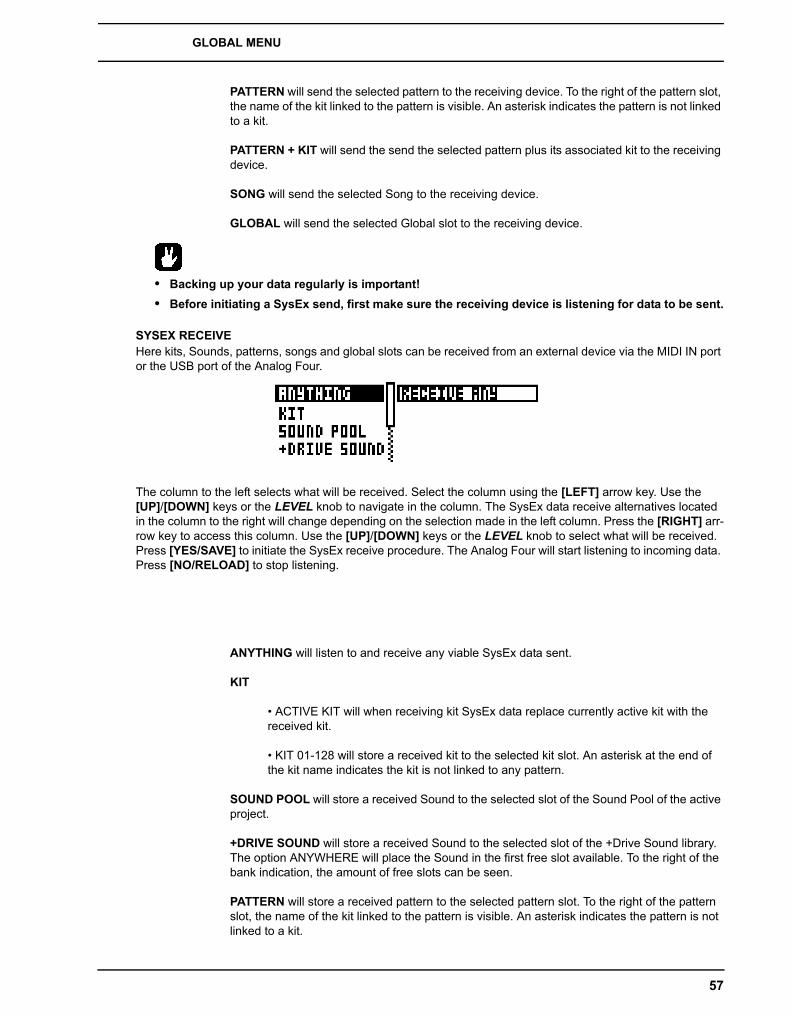
GLOBAL MENU
57
PATTERN will send the selected pattern to the receiving device. To the right of the pattern slot, the name of the kit linked to the pattern is visible. An asterisk indicates the pattern is not linked to a kit.
PATTERN + KIT will send the send the selected pattern plus its associated kit to the receiving device.
SONG will send the selected Song to the receiving device.
GLOBAL will send the selected Global slot to the receiving device.
• Backing up your data regularly is important!• Before initiating a SysEx send, first make sure the receiving device is listening for data to be sent.
SYSEX RECEIVEHere kits, Sounds, patterns, songs and global slots can be received from an external device via the MIDI IN port or the USB port of the Analog Four.
The column to the left selects what will be received. Select the column using the [LEFT] arrow key. Use the [UP]/[DOWN] keys or the LEVEL knob to navigate in the column. The SysEx data receive alternatives located in the column to the right will change depending on the selection made in the left column. Press the [RIGHT] arr-row key to access this column. Use the [UP]/[DOWN] keys or the LEVEL knob to select what will be received. Press [YES/SAVE] to initiate the SysEx receive procedure. The Analog Four will start listening to incoming data. Press [NO/RELOAD] to stop listening.
ANYTHING will listen to and receive any viable SysEx data sent.
KIT
• ACTIVE KIT will when receiving kit SysEx data replace currently active kit with the received kit.
• KIT 01-128 will store a received kit to the selected kit slot. An asterisk at the end of the kit name indicates the kit is not linked to any pattern.
SOUND POOL will store a received Sound to the selected slot of the Sound Pool of the active project.
+DRIVE SOUND will store a received Sound to the selected slot of the +Drive Sound library. The option ANYWHERE will place the Sound in the first free slot available. To the right of the bank indication, the amount of free slots can be seen.
PATTERN will store a received pattern to the selected pattern slot. To the right of the pattern slot, the name of the kit linked to the pattern is visible. An asterisk indicates the pattern is not linked to a kit.
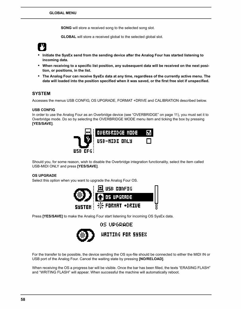
GLOBAL MENU
58
SONG will store a received song to the selected song slot.
GLOBAL will store a received global to the selected global slot.
• Initiate the SysEx send from the sending device after the Analog Four has started listening to incoming data.
• When receiving to a specific list position, any subsequent data will be received on the next posi-tion, or positions, in the list.
• The Analog Four can receive SysEx data at any time, regardless of the currently active menu. The data will loaded into the position specified when it was saved, or the first free slot if unspecified.
SYSTEMAccesses the menus USB CONFIG, OS UPGRADE, FORMAT +DRIVE and CALIBRATION described below.
USB CONFIGIn order to use the Analog Four as an Overbridge device (see “OVERBRIDGE” on page 11), you must set it to Overbridge mode. Do so by selecting the OVERBRIDGE MODE menu item and ticking the box by pressing [YES/SAVE].
Should you, for some reason, wish to disable the Overbridge integration functionality, select the item called USB-MIDI ONLY and press [YES/SAVE].
OS UPGRADESelect this option when you want to upgrade the Analog Four OS.
Press [YES/SAVE] to make the Analog Four start listening for incoming OS SysEx data.
For the transfer to be possible, the device sending the OS syx-file should be connected to either the MIDI IN or USB port of the Analog Four. Cancel the waiting state by pressing [NO/RELOAD].
When receiving the OS a progress bar will be visible. Once the bar has been filled, the texts “ERASING FLASH” and “WRITING FLASH” will appear. When successful the machine will automatically reboot.

GLOBAL MENU
59
• When performing the sending of the OS syx file, we recommend using our free SysEx utility C6. It can be downloaded from the Elektron website.
• If the Analog Four is receiving the OS upgrade through the MIDI ports, use the Elektron TM-1 USB MIDI interface for up to 10x transfer speeds.
FORMAT +DRIVEOffers the possibility to erase all content, all projects and sounds, stored on the +Drive. A prompt will appear asking if the formatting procedure should be executed. Press [YES/SAVE] to proceed with the formatting.
CALIBRATIONWilll start the calibration routine for the oscillators, pulse widths and filters. After selecting this option, a popup window asking to confirm the calibration will appear.
Press [YES/SAVE] to proceed with the calibration. Please note the calibration routine takes a while to complete.
• The Analog Four is factory calibrated. It should not be re-calibrated unless specifically stated by Elektron Support.

EARLY STARTUP MENU
60
EARLY STARTUP MENUTo access this menu, hold down the [FUNCTION] key while powering up the Analog Four. From here you can perform a variety of tasks. To choose the different alternatives, press the corresponding [TRIG] key.
TEST MODETo enter this mode, press the first [TRIG] key. If you have any trouble with your Analog Four and suspect it may be due to a hardware problem, perform this self test. No errors should be reported as shown below. If that is not the case, contact Elektron support or the retailer you bought the Analog Four from.
EMPTY RESETTo perform this operation, press the second [TRIG] key. All kits, patterns, Sounds and songs will be erased.
FACTORY RESETWhen performing a factory reset on the Analog Four it will overwrite and re-initialize the active project (including all pattern, kit, sound pool and global data). The +Drive project slot 1 will be overwritten and re-initialized. Sound bank A and B will be overwritten with the factory Sounds. Factory pre-set patterns, kits, Sounds and settings will be re-initialized.
If you wish to keep the active project, remember to save it to a +Drive project slot higher than 1 before you per-form a factory reset. To perform a factory reset, press [TRIG] key 3.
OS UPGRADEChoose this option by pressing the fourth [TRIG] key. The Analog Four will enter a waiting stage, listening for incoming OS data. For the transfer to be possible, the device sending the OS syx-file should be connected to the MIDI IN port of the Analog Four. USB MIDI transfers is not possible when in the EARLY START UP menu.
As the Analog Four receives the OS a progress bar will indicate the how much of the OS that has been received. When upgrading, the <TRIG> LEDs will light up one after another. Please note that this procedure takes a while. When the transfer is finished the message “PREPARING FLASH” appears. “PREPARING FLASH” is shortly fol-lowed by “UPDATING FLASH”. When this process is finished the OS is updated.
• When performing the sending of the OS syx file, we recommend using our free SysEx utility C6. It can be downloaded from the Elektron website.
• If the Analog Four is receiving the OS upgrade through the MIDI ports, use the Elektron TM-1 USB MIDI interface for up to 10x transfer speeds.

MORE ON OSCILLATORS, FILTERS AND ENVELOPES
61
MORE ON OSCILLATORS, FILTERS AND ENVELOPESIn this chapter the functionality of the oscillators, filters and envelopes will be explained in further detail.
OSCILLATORSSeveral waveforms are available to the two oscillators of each synth track. By adjusting the PW parameter, the waveshape can be changed on all types of waveforms, changing their timbre. Furthermore, each oscillator has a dedicated PWM LFO, giving animation to the sound by means of pulsewidth modulation.
SAW. This waveform has a biting, buzzy and distinct sound. It contains all harmonics, both odd and even, of the fundamental frequency. Classic synth basses, strings and brass sounds are often created using sawtooth wave-forms. The PW parameter brings in a second sawtooth, out of phase with the first one. Changing the PW value or engaging PWM varies the phase difference between the two, similar to having two slightly detuned oscillators running. This is useful to get a thicker sawtooth sound with more movement as different harmonics interfere with each other. To get a regular single sawtooth, set PW to mid position or either extreme value.
TRANSISTOR PULSE Transistor pulse is special sort of pulse waveform, suitable when you want to achieve acid-like sounds. It sounds a bit more shrill compared to the regular pulse waveform available to the oscillators. PW sets the width of the upper and lower parts of the wave, just like on the regular pulse waveform described below. The major difference is that one part of the transistor pulse waveform is not flat, but rather sloping a bit, thus displaying a slightly similar form as a sawtooth waveform. This introduces more even harmonics, making the sound less hollow. Extreme PW settings, positive or negative, will mute the waveform as the upper or lower part disappears completely. A change in pitch also changes the waveform and pulsewidth a bit, giving slightly different sound at different pitches.
PULSE When the PW parameter is set to its middle value of 0, a square wave will be produced. A square wave contains only odd-numbered harmonics of the fundamental frequency and has a hollow sound, not quite as full as a sawtooth waveform. Changing the PW makes the pulse waveform asymmetric, introducing even harmonics and making the sound thinner and more nasal. Using PWM to introduce pulsewidth modulation is the most clas-sic way of adding animation to a synthesizer waveform. When you want to recreate the sounds of old video games, square waves are very handy. Extreme PW settings, positive or negative, will mute the waveform, as the upper or lower part disappears completely.
TRIANGLE A triangle waveform has a mellow and dampened sound, reminiscent of a mix between a pure sine wave and a square wave. A triangle wave contains only odd-numbered harmonics, but at lower levels than a square wave. A low-pass filtered triangle wave will sound very much like a sine wave. The PW parameter intro-duces an edge in the waveform, gradually changing it from a pure triangle at mid position to a reversed sawtooth waveform at extreme PW settings.
SUB OSCILLATORS
Each oscillator features a sub oscillator, running at a fixed interval below the oscillator. By activating a sub oscil-lator, more depth and body will be added to the sound. The sub oscillators work as an extension of the regular oscillator pitch, but will however not be affected by neither waveshaping nor pulse width modulation. Four sub oscillator waveforms exist.
1OCT This option will add a square waveform one octave below the root note. The sub oscillator frequency is 1/2 of the oscillator frequency.
2OCT This option will add a square waveform two octaves below the root note. The sub oscillator frequency is 1/4 of the oscillator frequency.
2PUL This option will add a 25% pulse waveform two octaves below the root note. This selection sounds a bit similar to mixing the 1OCT and 2OCT types.

MORE ON OSCILLATORS, FILTERS AND ENVELOPES
62
5TH This option adds a 33% pulse waveform one perfect fifth, which is equivalent to seven semitones, below the oscillator. The sub oscillator thus operates at 2/3 of the oscillator frequency. If, for instance, the oscillator plays a G, then the sub oscillator will play the C below it. Together with the other oscillator, this makes it possible to play a simple chord using just one track of the Analog Four.
• To get a C minor chord (C, Eb, G), set the oscillator TUN parameter to +7 semitones (for the G), set the sub oscillator to 5TH (for the C), and set the other oscillator to +3 semitones (for the minor third, Eb). To get a C major chord, set the other oscillator to +4 instead (for the major third, E). Suspended chords are created by setting TUN of the other oscillator to +5 (the perfect fourth, F) for a Csus4 chord, or to +2 (the major second, D) for a Csus2 chord. Moreover, four-note chords like the major 7th chord (maj7) and minor 7th chord (m7) is possible by using both oscillators' sub oscillators in 5TH modes, as these chords consists of two perfect fifths. With oscillator coarse tune settings of +7 and +11 semitones (G and B, respectively) the sub oscillators will be placed at C and E notes, forming a C major 7th (Cmaj7) chord. Tuning the oscillators to +7 and +10 semi-tones instead (G and Bb) the sub oscillators end up at C and Eb, forming a C minor 7th (Cm7) chord. The desired chord can be heard when the keyboard or the sequencer plays a C note. When playing other notes, the chord will transpose accordingly, enabling simple chord progressions. Transitions between the minor and major variants can be done on step basis in the sequencer by parameter locking the TUN parameter of the other oscillator to +3 or +4 where desired.
OFF This turns off the sub oscillator completely. Note that it is otherwise on, regardless of the regular oscillator waveform setting. The oscillator's LEV setting then determines the level of the oscillator and sub oscillator com-bined.
OTHER OSCILLATOR WAVEFORM SELECTIONS
IN L Will use audio coming from the left external input as the audio source instead of the oscillator waveforms. The incoming audio can then be affected by the AM, the filters, the overdrive and the amplitude envelope of the track.
IN R Equivalent to IN L, but using the right external input.
FDB This setting is only available to OSCILLATOR 1. Instead of using the oscillator waveform as the audio source, the audio coming from the ladder filter output will be used. Just as with the oscillator, the LEV parameter sets the level of this signal path. Turning it up high can introduce a self-oscillating feedback useful for drums or uncontrolled screams. The filter cutoff and resonance settings also affect the feedback behavior. On more mod-erate levels, it will give a more overloaded sound character to whatever enters the filter from OSC2, similar to the external feedback patch known from certain 1970s synths.
NEI This setting is only available in the OSCILLATOR 2 menu. It will route the audio of the multimode filter out-put of the track preceding the track being edited. This audio can then be affected by the AM, the filters, the over-drive and the amplitude envelope of the track. In this way track 1 can be sent to track 2, track 2 to track 3, track 3 to track 4. For a completely serial routing, turn down the LVL setting of the routed track completely. This set-ting does nothing on track 1.
OFF This will turn off the oscillator completely. The sub oscillator is not affected though.
• The AM functionality between the oscillators still exists when using filter feedback, neighbor, and external inputs as the OSC1/OSC2 waveforms. I.e., other signals than oscillator signals can be subject to amplitude modulation.

MORE ON OSCILLATORS, FILTERS AND ENVELOPES
63
FILTERS
4-POLE LADDER FILTERThere is no way to turn the ladder filter completely off, but turning up the cutoff frequency will pass all frequen-cies through. It should be noted that zero resonance does not give the flattest frequency response – instead it drops some decibels both in the treble and in the bass. The flattest response is reached when resonance is somewhere around 25, which is also the default value.
2-POLE MULTI MODE FILTERThere is no way to turn the multimode filter completely off, but if no filtering is desired there are a number of good ways to let all audio pass through unaffected by the filter:
HP2 at minimum frequency, no resonance.
BS at minimum frequency, no resonance.
LP2 at maximum frequency, no resonance.
PK at max frequency, no resonance.
PK at min frequency, no resonance. Note: this gives an inverted signal.
LP2 This 12 dB/octave lowpass mode attenuates frequencies above the cutoff frequency with twelve decibels per octave, similarly to most other classic 2-pole VCFs. The amount of resonance determines how much the fre-quencies around the cutoff frequency will be boosted. The sound of this filter is cleaner than the ladder filter, and their different sonic characters are both worth trying out. If combined, they can add up to an extraordinarily steep 6-pole filter.
LP1 This unorthodox 6 dB/octave lowpass mode has a less steep attenuation slope above the cutoff frequency than the LP2 mode. More high frequency content will thus be retained, making the filtering less aggressive. The slope is gentle like a 1-pole filter – which normally cannot have resonance – but works in essence like a 2-pole filter with a resonance peak. The amount of resonance determines how much the frequencies around the cutoff frequency will be boosted. The LP1 mode is useful for equalizer duties without resonance, or for adding a reso-nance with just a hint of lowpass softness.
BP The bandpass filter gradually attenuates frequencies above and below the cutoff frequency with a slope of 6 dB/octave. The resonance setting controls how much the frequencies around the cutoff frequency will be boosted. The bandpass filter is good for isolating a sound in the frequency spectrum, making it easier to blend with other sounds in a mix.
HP1 This unusual 6 dB/octave highpass filter attenuates frequencies below the cutoff frequency with a less steep slope than the HP2 mode. The amount of resonance determines how much the frequencies around the cutoff point will be boosted. Besides ordinary highpass filter effects, the HP1 mode without resonance is useful for removing some of the bass of a sound, which in turn is helpful when you want to avoid a muddy mix.
HP2 This is a classic 12 dB/octave highpass filter, attenuating frequencies below the cutoff frequency. The filter slope is steeper compared to the highpass 1 filter, thus filtering out more low-frequency content. The amount of resonance determines how much the frequencies around the cutoff point will be boosted. A highpass filter is suitable when creating lead sounds or hi-hats.
BS The band-stop filter, also known as a band-reject or notch filter, works as an inverted bandpass filter. Signals around the cutoff frequency will be attenuated the most, while frequencies above and below the cutoff frequency gradually will become less and less affected. The higher the resonance, the narrower the filter notch will be. This means that in contrast to the other filter modes, the effect of the resonance parameter is greatest at a low set-ting, giving a wider notch. This filter shape is useful for both basic equalizer duties and for unique filter effects. For example: sweeping the cutoff frequency with an LFO gives a phaser-sounding filter effect. Controlling it with an envelope while at the same time using the ladder filter gives a more complex filter sound. Static filter settings can give a somewhat acoustic resonant quality to sounds, especially transient-heavy ones.
PK The peak filter passes all the sound, boosting frequencies around the cutoff frequency. The higher the reso-nance, the more they will be boosted. A peak filter comes in handy when you want to highlight a certain charac-

MORE ON OSCILLATORS, FILTERS AND ENVELOPES
64
teristic of a sound, by for example adding more low end or more mid end. It can be used either statically, like the peak of a parametric equalizer, or dynamically, controlled by for example an LFO or envelope.
ENVELOPESThe amplitude envelopes and the assignable envelopes offer 12 different shapes, consisting of six basic shapes each with two different trigging behaviors. The envelope shape graphics give an indication of how the envelope will affect the modulation destination. The left portion of the graphics shows how the envelope behaves when it is rising, i.e. the attack phase, and to the right the falling behavior is shown, i.e. decay and release. The rise and fall can each be either linear or exponential, useful in different applications as described below. A dot to the left of the visual representation of the envelope indicates that the envelope will restart from level zero each time it is trigged. Envelope shapes without a dot means the envelope will start from the level it had when being trigged.
0-1: Linear attack and decay/release. An envelope shape suitable for controlling the filters if linear attack/decay/release sweeps are desired. When used as an amplitude envelope the decay and release phase appears to drop quicker towards the end, making it most useful for sounds that should fade out without a tail.
2-3 This can be considered the standard envelope shape. Decay and release fall quicker in the beginning of their phase, behaving more snappy and – just like acoustic sounds tend to do – leaving a tail instead of ending abruptly. This envelope shape is useful for creating distinct sounds, for example kick drums and basses, but also lengthier sounds like pads.
4-5 Exponential attack, linear decay/release. This shape makes the envelope rise quicker and quicker. This envelope is suitable when for example creating sounds appearing to be played in reverse or for sounds requir-ing a sudden attack.
6-7 Exponential attack, exponential decay/release. Since our hearing perceives loudness exponentially, this shape is primarily useful as an amplitude envelope for very long sounds that are supposed to fade in and fade out at a very constant rate. When used as a filter envelope, very clicky, whip lash-like sounds can also be obtained by using this shape.
8-9 Full attack, linear decay/release. The envelope will immediately rise to the full envelope level and stay there for the whole attack phase. The ATK parameter sets the duration of this attack phase. The envelope shape is useful as amplitude envelope for certain percussive sounds that need a punch at full volume followed by a quick decay, or for other sounds that should contain a full body before being entering the decay phase.
10-11 Full attack, exponential decay/release. The envelope behaves like the aforementioned shape 8-9, but decay and release will fall in a more snappy fashion, ending with a tail. This makes it even more useful for per-cussive sounds.
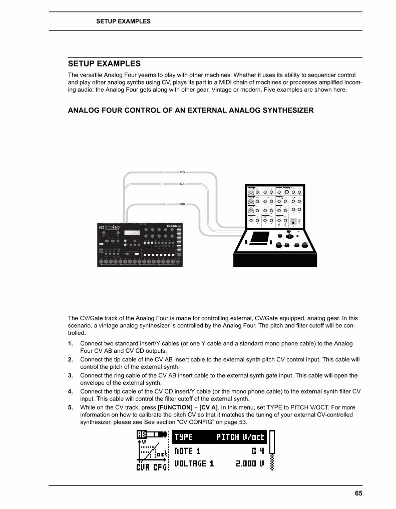
SETUP EXAMPLES
65
SETUP EXAMPLESThe versatile Analog Four yearns to play with other machines. Whether it uses its ability to sequencer control and play other analog synths using CV, plays its part in a MIDI chain of machines or processes amplified incom-ing audio: the Analog Four gets along with other gear. Vintage or modern. Five examples are shown here.
ANALOG FOUR CONTROL OF AN EXTERNAL ANALOG SYNTHESIZER
The CV/Gate track of the Analog Four is made for controlling external, CV/Gate equipped, analog gear. In this scenario, a vintage analog synthesizer is controlled by the Analog Four. The pitch and filter cutoff will be con-trolled.
1. Connect two standard insert/Y cables (or one Y cable and a standard mono phone cable) to the Analog Four CV AB and CV CD outputs.
2. Connect the tip cable of the CV AB insert cable to the external synth pitch CV control input. This cable will control the pitch of the external synth.
3. Connect the ring cable of the CV AB insert cable to the external synth gate input. This cable will open the envelope of the external synth.
4. Connect the tip cable of the CV CD insert/Y cable (or the mono phone cable) to the external synth filter CV input. This cable will control the filter cutoff of the external synth.
5. While on the CV track, press [FUNCTION] + [CV A]. In this menu, set TYPE to PITCH V/OCT. For more information on how to calibrate the pitch CV so that it matches the tuning of your external CV-controlled synthesizer, please see See section “CV CONFIG” on page 53.
PITCH
GATE
FILTER
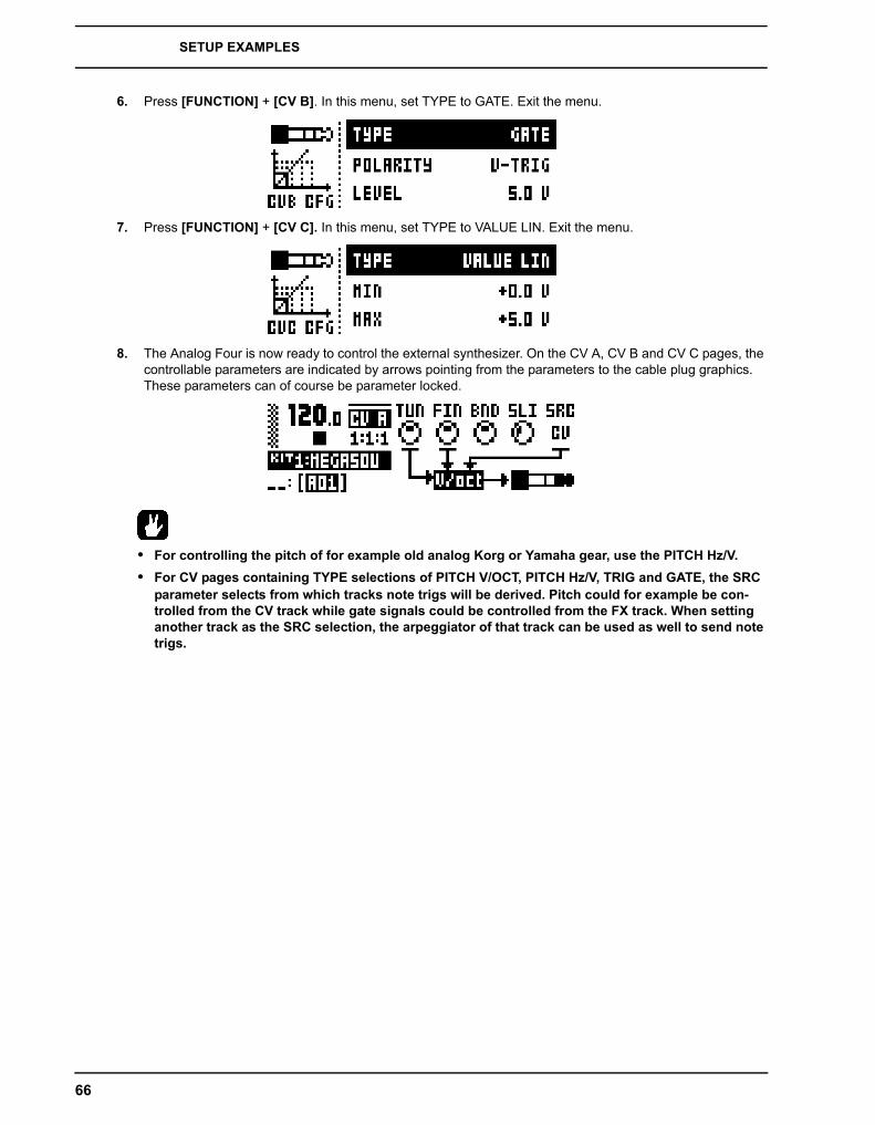
SETUP EXAMPLES
66
6. Press [FUNCTION] + [CV B]. In this menu, set TYPE to GATE. Exit the menu.
7. Press [FUNCTION] + [CV C]. In this menu, set TYPE to VALUE LIN. Exit the menu.
8. The Analog Four is now ready to control the external synthesizer. On the CV A, CV B and CV C pages, the controllable parameters are indicated by arrows pointing from the parameters to the cable plug graphics. These parameters can of course be parameter locked.
• For controlling the pitch of for example old analog Korg or Yamaha gear, use the PITCH Hz/V.• For CV pages containing TYPE selections of PITCH V/OCT, PITCH Hz/V, TRIG and GATE, the SRC
parameter selects from which tracks note trigs will be derived. Pitch could for example be con-trolled from the CV track while gate signals could be controlled from the FX track. When setting another track as the SRC selection, the arpeggiator of that track can be used as well to send note trigs.
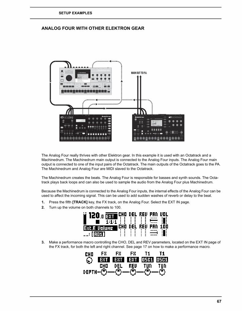
SETUP EXAMPLES
67
ANALOG FOUR WITH OTHER ELEKTRON GEAR
The Analog Four really thrives with other Elektron gear. In this example it is used with an Octatrack and a Machinedrum. The Machinedrum main output is connected to the Analog Four inputs. The Analog Four main output is connected to one of the input pairs of the Octatrack. The main outputs of the Octatrack goes to the PA. The Machinedrum and Analog Four are MIDI slaved to the Octatrack.
The Machinedrum creates the beats. The Analog Four is responsible for basses and synth sounds. The Octa-track plays back loops and can also be used to sample the audio from the Analog Four plus Machinedrum.
Because the Machinedrum is connected to the Analog Four inputs, the internal effects of the Analog Four can be used to affect the incoming signal. This can be used to add sudden washes of reverb or delay to the beat.
1. Press the fifth [TRACK] key, the FX track, on the Analog Four. Select the EXT IN page.2. Turn up the volume on both channels to 100.
3. Make a performance macro controlling the CHO, DEL and REV parameters, located on the EXT IN page of the FX track, for both the left and right channel. See page 17 on how to make a performance macro.
MAIN OUT TO P.A.

SETUP EXAMPLES
68
ANALOG FOUR AS A FILTER BANK
Thanks to the neighbor routing, all the filters of the Analog Four can be used for providing an immense mono fil-terbank consisting of 8 filters plus 4 overdrive circuits. The setup can be either serial or parallel. It can of course be set up for stereo filtering as well. In this scenario 4 filters are available for the left and right channels.
In this example, the two filters of each track will be used in parallel with the filters of the other tracks.
Bild
1. Connect the outputs of for example a Machinedrum to the inputs of the Analog Four.2. For all four synth tracks, set the WAV parameter in the OSC1 page to IN R, and the WAV parameter of
OSC2 to IN L. This will sum the left and right channels.
3. Set all other WAV parameters to OFF. Make sure all SUB parameters is set to OFF as well.

SETUP EXAMPLES
69
4. On the AMP page for all tracks, make sure ATK is 0, DEC 0, SUS 127 and REL INF.
5. On the FILTER page for all tracks, the DEP parameters should be set to 0.
6. Place note trigs on the first step of the sequencer. It is necessary to trig the amplitude envelope.7. Press play on the Machinedrum.8. Press play on the Analog Four. The filters of the synth tracks can now be used to shape the incoming
Machinedrum sound.
• For serial filtering, make either one or both oscillators of synth track 1 listen to the external inputs. Set the WAV parameter of oscillator 2 to NEI on the other tracks. Turn off oscillator 1 on tracks 2-4. Turn down the track level to 0 for tracks 1-3.
• Make the Analog Four listen to MIDI clock and transport controls sent from the Machinedrum. When pressing play on the Machinedrum sequencer, both units will start to play at the same time and in the same BPM. Experiment with the tempo-synced LFOs of the Analog Four controlling the filter parameters.
• Place other note trigs on the Analog Four sequencer and experiment with the filter envelope set-tings.
• When using the Analog Four as a stereo filter, let track 1-2 take care of the left signal and track 3-4 take care of the right. Don’t forget to pan the synth tracks responsible for the left and right chan-nels hard left and right. If you wish to control the FRQ or RES parameters of the left and right tracks simultaneously, use a performance macro.

SETUP EXAMPLES
70
USING AN EXTERNAL OSCILLATOR WITH THE ANALOG FOUR
The CV/Gate outputs and the external inputs allow an external oscillator to be used with the internal Analog Four oscillators. Use this trick when you want a different (perhaps old, quirky and unpredictable yet charming) oscillator to provide the fundamental tone but still want the control and modulation power of the Analog Four.
In this setup example, the CV track will trig the oscillator of an external analog synth. The output of this oscillator will be routed to left input of the Analog Four. Synth track 1 of the Analog Four will control the pitch of both the internal oscillators and the external oscillator. The filters and envelopes of track 1 will shape both the internal and the external oscillators.
1. Connect a standard mono phone (or insert/Y) cable to the Analog Four CV AB output.2. Connect the output of the external oscillator to the left external input3. Connect the mono phone (or tip of the insert/Y) cable from CV AB to the pitch CV control input of the exter-
nal synth.4. Select the CV track and press [FUNCTION] + [CV A]. In this menu, depending on the specification of the
external analog synth, set TYPE to either PITCH V/OCT or PITCH Hz/V. For more information on how to calibrate the pitch CV so that it matches the tuning of your external CV-controlled synthesizer, please see See section “CV CONFIG” on page 53.
AUDIO OUT
PITCH

SETUP EXAMPLES
71
5. Set the SRC parameter of the CV A page to TR1. This will make the CV track send out pitch voltages according to the note trigs on synth track 1.
6. Select track 1. Set WAV on the OSC1 page to IN L. For oscillator 2, choose one of the internal Analog Four waveforms.
7. Note trigs placed on track 1 will now control both the internal and the external oscillators.
• Use parameter locks to alternate the waveform of oscillator 1 between external/internal selections.• This example can use more than one external oscillator. If two separate external oscillators are
connected to the Analog Four external inputs, both oscillators can be used on for example track 1. Track 2-4 could then use only internal oscillators.

SETUP EXAMPLES
72
ANALOG FOUR WITH AN ELECTRIC GUITAR
In this setup example the Analog Four is used for proccessing the sound output from an electric guitar. The first, most basic method uses the FX track to turn the Analog Four into an effects box sporting the Wideshift Chorus, Saturator Delay and Supervoid Reverb effects. The second, more elaborate method routes the sound through Track 1 and allows all the sound-shaping possibilities offered by the FILTERS, AMP, ENV and LFO.
1. Connect the electric guitar to the audio input of an amplifier using a standard mono phone cable.2. Connect the audio out from the amplifier to the left audio input of the Analog Four.3. First method: Select the FX track on the Analog Four with [TRACK] key 5.To make use of the Wideshift
Chorus, press [PARAMETER] key 3, CHORUS. Change the volume and other aspects of the effect using the DATA ENTRY knobs. Use Saturator Delay and Supervoid Reverb effects in a similar manner by press-ing [PARAMETER] key 4, DELAY and key 5, REVERB respectively.
4. Second method: Select Track 1 on the Analog Four by pressing [TRACK] key 1.5. On the OSC1 menu page, set the WAV parameter to IN L using DATA ENTRY knob F. Set SUB, the sub
oscillator, to off. Turn the LEV all the way up.
REVERB EQ VOLUME GAIN
INPUT
OUTPUT
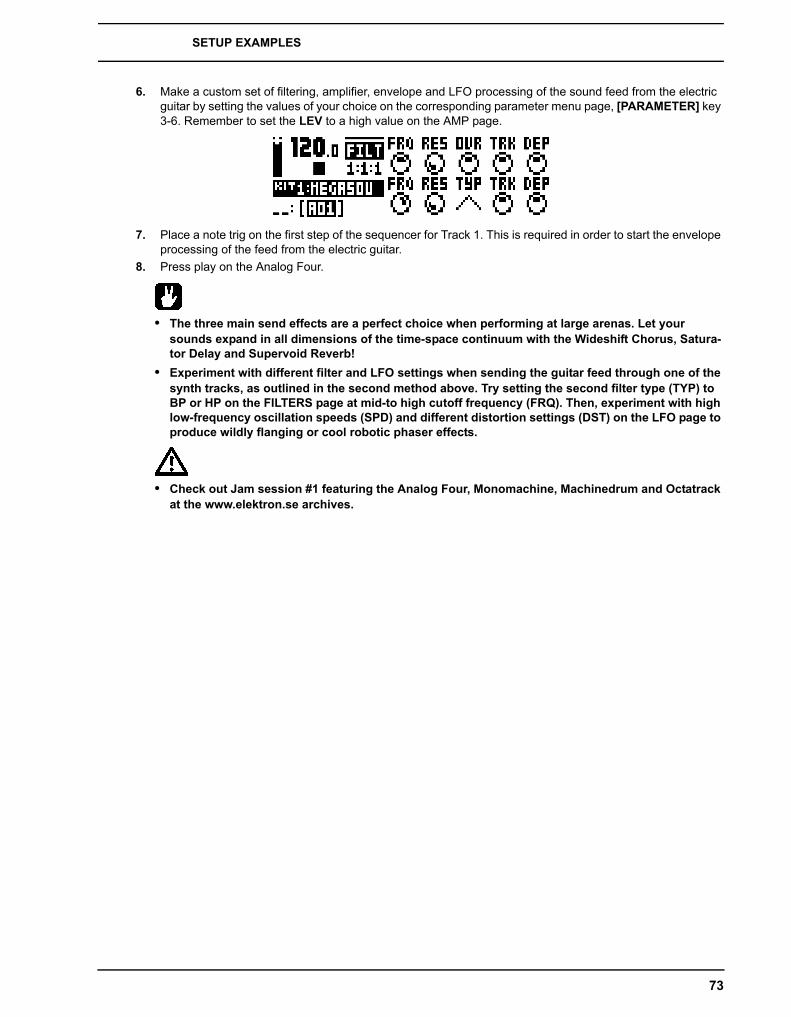
SETUP EXAMPLES
73
6. Make a custom set of filtering, amplifier, envelope and LFO processing of the sound feed from the electric guitar by setting the values of your choice on the corresponding parameter menu page, [PARAMETER] key 3-6. Remember to set the LEV to a high value on the AMP page.
7. Place a note trig on the first step of the sequencer for Track 1. This is required in order to start the envelope processing of the feed from the electric guitar.
8. Press play on the Analog Four.
• The three main send effects are a perfect choice when performing at large arenas. Let your sounds expand in all dimensions of the time-space continuum with the Wideshift Chorus, Satura-tor Delay and Supervoid Reverb!
• Experiment with different filter and LFO settings when sending the guitar feed through one of the synth tracks, as outlined in the second method above. Try setting the second filter type (TYP) to BP or HP on the FILTERS page at mid-to high cutoff frequency (FRQ). Then, experiment with high low-frequency oscillation speeds (SPD) and different distortion settings (DST) on the LFO page to produce wildly flanging or cool robotic phaser effects.
• Check out Jam session #1 featuring the Analog Four, Monomachine, Machinedrum and Octatrack at the www.elektron.se archives.

TECHNICAL INFORMATION
74
TECHNICAL INFORMATION
SPECIFICATIONSTHE SEQUENCER
4 synth tracks1 FX track1 CV/Gate track128 projects (+Drive)4096 sounds (+Drive Sound library)128 patterns (per project)Up to 64 steps per pattern128 Sounds (per project)128 Kits (per project)16 Songs (per project)6× arpeggiatorsIndividual track lengthsSwing, slide and accent functionsTrack transposeMicro timingParameter locksLive friendly Performance modeSound-per-step changeInstant kit, pattern, track and Sound reloadFull real-time control
SEND EFFECTS
Wideshift ChorusSaturator DelaySupervoid Reverb
SYNTH VOICE (x4)
Fully analog signal path2× analog oscillatorsVariable waveshape on all waveformsOscillator AM and Sync modes2× sub-oscillators1× noise generator1× 4-pole analog lowpass ladder filter1× 2-pole analog multi-mode filter1× analog overdrive circuitFilter feedback2× assignable LFOs1× dedicated vibrato LFO2× dedicated waveshape LFOs1× amp envelope2× assignable envelopes2× dedicated LFO fade envelopes1× dedicated noise fade envelope1× dedicated vibrato envelope1× dedicated autobend envelope3x individual effect sendsMIDI control
FEATURES
Up to 4-Note Polyphony/Multitimbral/Unison+Drive enables multiple (x128) projects
ELECTRICAL SPECIFICATIONS
Impedance balanced audio outputs:
Headphones out level: +19 dBu (55 �Main outputs level: +19 dBuOutput impedance: 440� �unbalanced
Unbalanced audio inputs:
Input level: +19 dBu maximumAudio input impedance: 9 kDigital S/N ratio: 102 dBFS (20-20.000 Hz)
Unit power consumption: 8 W typical, 18 W maximum.
Recommended power supply: 12 V DC, 2 A
HARDWARE
122x32 pixel backlit LCDMIDI In/Out/Thru with DIN Sync out2 x 1/4” impedance balanced audio out jacks2 x 1/4” audio in jacks1 x 1/4” stereo headphone jack2 x 1/4” dual CV/Gate outputs48 kHz, 24-bit D/A and A/D convertersFlash-EEPROM upgradable OSElectrically isolated USB 2.0 port
PHYSICAL SPECIFICATIONS
Steel casingDimensions: W340xD176xH63mm (including knobs, jacks and feet)Weight: approximately 2.4 kg
POWER SUPPLY (PSU-3) ELECTRICAL SPECIFICATIONS
Input voltage range: 100-240 V (43-60Hz)Input connector: IEC320-C8 (2 prong)In-rush current: 40-60 A maximum
Output voltage: 12 V DCOutput current: 2.5 A maximumOutput connector: 5.5x2.5 mm DC plug, power at center
:
:
:
CREDITS AND CONTACT INFORMATION
75
CREDITS AND CONTACT INFORMATION
CREDITS
PRODUCT DESIGN AND DEVELOPMENTOscar AlbinssonMagnus ForsellAnders GärderJimmy MyhrmanJon MårtenssonDavid ReveljMattias RickardssonDaniel Troberg
ADDITIONAL DESIGNThomas Ekelund
FACTORY DEFAULT SOUND DESIGNRichard DevineJimmy MyhrmanSimon MattissonJimmy MyhrmanJon MårtenssonDaniel TrobergCenk SayinliCharlie StormNicholas LemAlex SchetterDaren Ager
REFERENCE MANUALUfuk DemirThomas EkelundJon MårtenssonDaniel Sterner
CONTACT INFORMATION
ELEKTRON WEBSITEhttp://www.elektron.se
DELIVERY ADDRESSElektron Music Machines MAV ABSockerbruket 9SE-414 51 GothenburgSweden
TELEPHONE+46 (0)31 743 744 0

CREDITS AND CONTACT INFORMATION
76
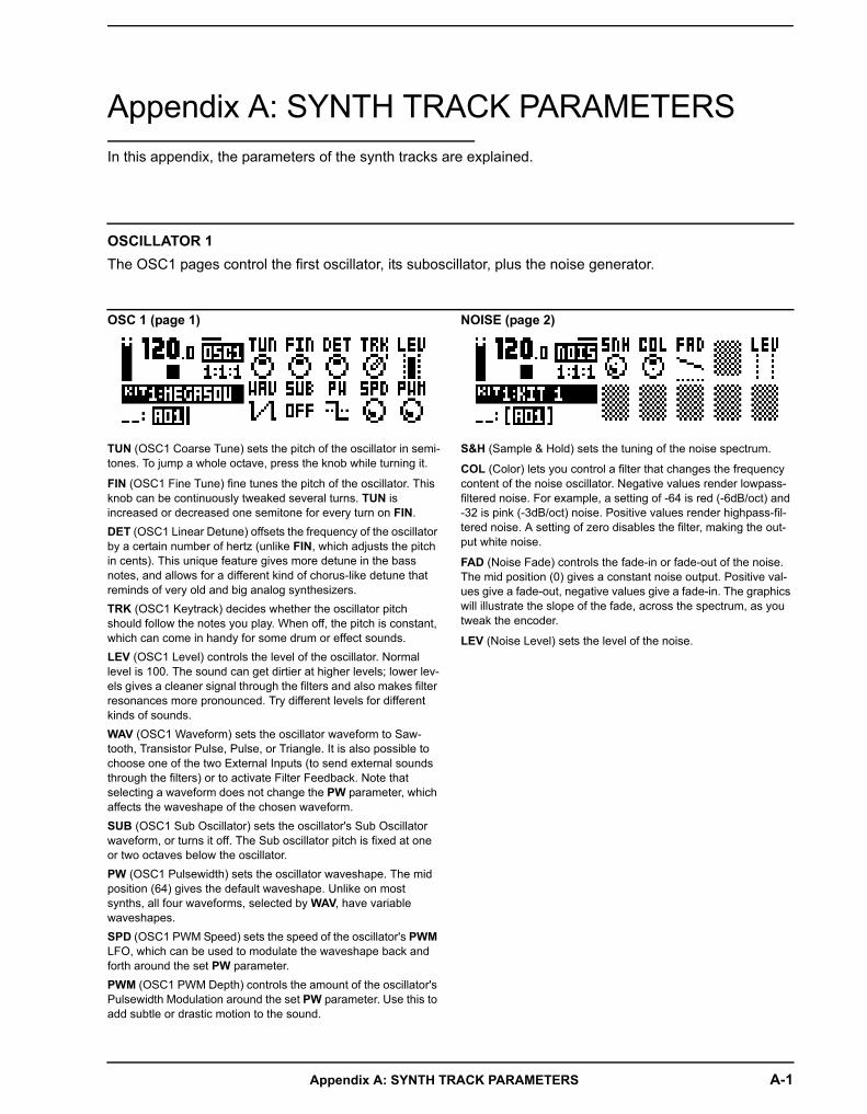
Appendix A: SYNTH TRACK PARAMETERS A-1
Appendix A: SYNTH TRACK PARAMETERSIn this appendix, the parameters of the synth tracks are explained.
OSC 1 (page 1)
TUN (OSC1 Coarse Tune) sets the pitch of the oscillator in semi-tones. To jump a whole octave, press the knob while turning it.
FIN (OSC1 Fine Tune) fine tunes the pitch of the oscillator. This knob can be continuously tweaked several turns. TUN is increased or decreased one semitone for every turn on FIN.DET (OSC1 Linear Detune) offsets the frequency of the oscillator by a certain number of hertz (unlike FIN, which adjusts the pitch in cents). This unique feature gives more detune in the bass notes, and allows for a different kind of chorus-like detune that reminds of very old and big analog synthesizers.TRK (OSC1 Keytrack) decides whether the oscillator pitch should follow the notes you play. When off, the pitch is constant, which can come in handy for some drum or effect sounds.LEV (OSC1 Level) controls the level of the oscillator. Normal level is 100. The sound can get dirtier at higher levels; lower lev-els gives a cleaner signal through the filters and also makes filter resonances more pronounced. Try different levels for different kinds of sounds.WAV (OSC1 Waveform) sets the oscillator waveform to Saw-tooth, Transistor Pulse, Pulse, or Triangle. It is also possible to choose one of the two External Inputs (to send external sounds through the filters) or to activate Filter Feedback. Note that selecting a waveform does not change the PW parameter, which affects the waveshape of the chosen waveform.SUB (OSC1 Sub Oscillator) sets the oscillator's Sub Oscillator waveform, or turns it off. The Sub oscillator pitch is fixed at one or two octaves below the oscillator.PW (OSC1 Pulsewidth) sets the oscillator waveshape. The mid position (64) gives the default waveshape. Unlike on most synths, all four waveforms, selected by WAV, have variable waveshapes. SPD (OSC1 PWM Speed) sets the speed of the oscillator's PWM LFO, which can be used to modulate the waveshape back and forth around the set PW parameter.PWM (OSC1 PWM Depth) controls the amount of the oscillator's Pulsewidth Modulation around the set PW parameter. Use this to add subtle or drastic motion to the sound.
NOISE (page 2)
S&H (Sample & Hold) sets the tuning of the noise spectrum.
COL (Color) lets you control a filter that changes the frequency content of the noise oscillator. Negative values render lowpass-filtered noise. For example, a setting of -64 is red (-6dB/oct) and -32 is pink (-3dB/oct) noise. Positive values render highpass-fil-tered noise. A setting of zero disables the filter, making the out-put white noise.
FAD (Noise Fade) controls the fade-in or fade-out of the noise. The mid position (0) gives a constant noise output. Positive val-ues give a fade-out, negative values give a fade-in. The graphics will illustrate the slope of the fade, across the spectrum, as you tweak the encoder.
LEV (Noise Level) sets the level of the noise.
OSCILLATOR 1The OSC1 pages control the first oscillator, its suboscillator, plus the noise generator.
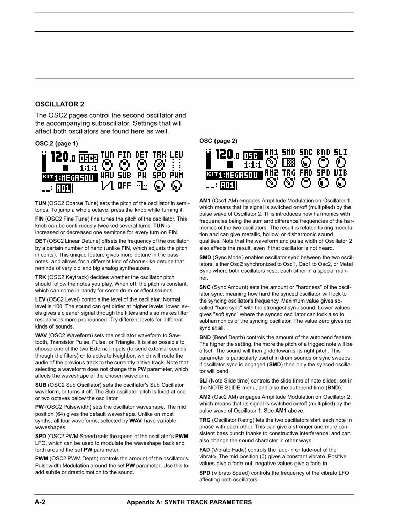
A-2 Appendix A: SYNTH TRACK PARAMETERS
OSCILLATOR 2The OSC2 pages control the second oscillator and the accompanying suboscillator. Settings that will affect both oscillators are found here as well.
OSC 2 (page 1)
TUN (OSC2 Coarse Tune) sets the pitch of the oscillator in semi-tones. To jump a whole octave, press the knob while turning it.FIN (OSC2 Fine Tune) fine tunes the pitch of the oscillator. This knob can be continuously tweaked several turns. TUN is increased or decreased one semitone for every turn on FIN.DET (OSC2 Linear Detune) offsets the frequency of the oscillator by a certain number of hertz (unlike FIN, which adjusts the pitch in cents). This unique feature gives more detune in the bass notes, and allows for a different kind of chorus-like detune that reminds of very old and big analog synthesizers.TRK (OSC2 Keytrack) decides whether the oscillator pitch should follow the notes you play. When off, the pitch is constant, which can come in handy for some drum or effect sounds.LEV (OSC2 Level) controls the level of the oscillator. Normal level is 100. The sound can get dirtier at higher levels; lower lev-els gives a cleaner signal through the filters and also makes filter resonances more pronounced. Try different levels for different kinds of sounds.WAV (OSC2 Waveform) sets the oscillator waveform to Saw-tooth, Transistor Pulse, Pulse, or Triangle. It is also possible to choose one of the two External Inputs (to send external sounds through the filters) or to activate Neighbor, which will route the audio of the previous track to the currently active track. Note that selecting a waveform does not change the PW parameter, which affects the waveshape of the chosen waveform.SUB (OSC2 Sub Oscillator) sets the oscillator's Sub Oscillator waveform, or turns it off. The Sub oscillator pitch is fixed at one or two octaves below the oscillator.PW (OSC2 Pulsewidth) sets the oscillator waveshape. The mid position (64) gives the default waveshape. Unlike on most synths, all four waveforms, selected by WAV, have variable waveshapes. SPD (OSC2 PWM Speed) sets the speed of the oscillator's PWM LFO, which can be used to modulate the waveshape back and forth around the set PW parameter.PWM (OSC2 PWM Depth) controls the amount of the oscillator's Pulsewidth Modulation around the set PW parameter. Use this to add subtle or drastic motion to the sound.
OSC (page 2)
AM1 (Osc1 AM) engages Amplitude Modulation on Oscillator 1, which means that its signal is switched on/off (multiplied) by the pulse wave of Oscillator 2. This introduces new harmonics with frequencies being the sum and difference frequencies of the har-monics of the two oscillators. The result is related to ring modula-tion and can give metallic, hollow, or disharmonic sound qualities. Note that the waveform and pulse width of Oscillator 2 also affects the result, even if that oscillator is not heard.
SMD (Sync Mode) enables oscillator sync between the two oscil-lators, either Osc2 synchronized to Osc1, Osc1 to Osc2, or Metal Sync where both oscillators reset each other in a special man-ner.
SNC (Sync Amount) sets the amount or "hardness" of the oscil-lator sync, meaning how hard the synced oscillator will lock to the syncing oscillator's frequency. Maximum value gives so-called "hard sync" with the strongest sync sound. Lower values gives "soft sync" where the synced oscillator can lock also to subharmonics of the syncing oscillator. The value zero gives no sync at all.
BND (Bend Depth) controls the amount of the autobend feature. The higher the setting, the more the pitch of a trigged note will be offset. The sound will then glide towards its right pitch. This parameter is particularly useful in drum sounds or sync sweeps; if oscillator sync is engaged (SMD) then only the synced oscilla-tor will bend.
SLI (Note Slide time) controls the slide time of note slides, set in the NOTE SLIDE menu, and also the autobend time (BND).
AM2 (Osc2 AM) engages Amplitude Modulation on Oscillator 2, which means that its signal is switched on/off (multiplied) by the pulse wave of Oscillator 1. See AM1 above.
TRG (Oscillator Retrig) lets the two oscillators start each note in phase with each other. This can give a stronger and more con-sistent bass punch thanks to constructive interference, and can also change the sound character in other ways.
FAD (Vibrato Fade) controls the fade-in or fade-out of the vibrato. The mid position (0) gives a constant vibrato. Positive values give a fade-out, negative values give a fade-in.
SPD (Vibrato Speed) controls the frequency of the vibrato LFO affecting both oscillators.

Appendix A: SYNTH TRACK PARAMETERS A-3
FILTERSIn the FILTERS page, settings that will affect the two track filters are found.
FILTERS
FRQ (Filter1 Frequency) controls the cutoff frequency of Filter 1, the 4-pole lowpass transistor ladder filter.
RES (Filter1 Resonance) controls the resonance of Filter 1. Increased resonance introduces a peak in the spectrum at the cutoff frequency. By design, Filter 1 has a stronger resonance in the higher frequencies, which gives a characteristic electronic fil-ter sound when the resonance starts sharp and then falls during a falling filter envelope.
OVR (Filter1 Overdrive) introduces distortion in the signal path. In mid position (0) the signal is kept clean. Increasing positive values gives a clipping distortion after Filter 1. Increasing nega-tive values also distorts the signal, but with a softer overdrive inside the filter.
TRK (Filter1 Keytrack) lets the cutoff frequency follow the pitch of the sound played. A setting of 32 will make the filter track the oscillator frequency in note intervals, making it possible to play the Filter 1 resonance the same way as an oscillator is played.
DEP (Filter1 EnvF Depth) controls the amount of cutoff fre-quency modulation from the filter envelope EnvF. The knob is bipolar, meaning that both negative and positive modulation depth is available. Note that ENV always affects Filter1, regard-less of which modulation destinations are chosen.
FRQ (Filter2 Frequency) controls the cutoff frequency of Filter 2, which is the 2-pole multimode filter located after Filter 1 and Overdrive.
RES (Filter2 Resonance) controls the resonance of Filter 2. Increased resonance introduces a peak in the spectrum at the cutoff frequency. (Except for the Bandstop filter type, which has a notch instead of a peak. This notch is widest at the lowest Reso-nance setting.) Compared to Filter 1, Filter 2 has a more uniform resonance behavior over the whole audio spectrum.
TYP (Filter2 Type) selects the filter type of Filter 2. Seven types are available: 2-pole Lowpass, 1-pole Lowpass, Bandpass, 1-pole Highpass, 2-pole Highpass, Bandstop, and Peak. Techni-cally all of them are 2-pole filters with resonance, but the "1-pole" types have a flatter spectrum like simple 1-pole filters and can be very useful also for equalizer duties.
TRK (Filter2 Keytrack) lets the cutoff frequency follow the pitch of the sound played. A setting of 32 will make the filter track the oscillator frequency in note intervals.
DEP (Filter2 EnvF Depth) controls the amount of cutoff fre-quency modulation from the filter envelope EnvF. The knob is
bipolar, meaning that both negative and positive modulation depth is available. Note that ENV always affects Filter2, regard-less of which modulation destinations are chosen.
VIB (Vibrato Depth) sets the amount of vibrato, ranging from subtle variations to wild sweeps.
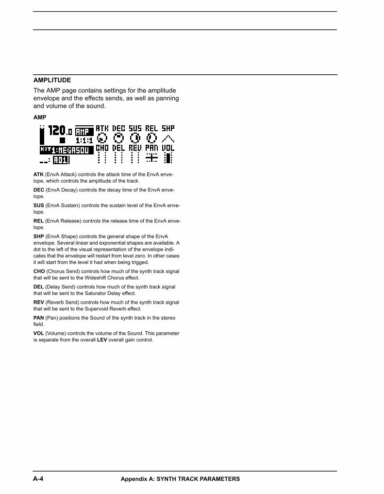
A-4 Appendix A: SYNTH TRACK PARAMETERS
AMPLITUDEThe AMP page contains settings for the amplitude envelope and the effects sends, as well as panning and volume of the sound.
AMP
ATK (EnvA Attack) controls the attack time of the EnvA enve-lope, which controls the amplitude of the track.
DEC (EnvA Decay) controls the decay time of the EnvA enve-lope.
SUS (EnvA Sustain) controls the sustain level of the EnvA enve-lope.
REL (EnvA Release) controls the release time of the EnvA enve-lope.
SHP (EnvA Shape) controls the general shape of the EnvA envelope. Several linear and exponential shapes are available. A dot to the left of the visual representation of the envelope indi-cates that the envelope will restart from level zero. In other cases it will start from the level it had when being trigged.
CHO (Chorus Send) controls how much of the synth track signal that will be sent to the Wideshift Chorus effect.
DEL (Delay Send) controls how much of the synth track signal that will be sent to the Saturator Delay effect.
REV (Reverb Send) controls how much of the synth track signal that will be sent to the Supervoid Reverb effect.
PAN (Pan) positions the Sound of the synth track in the stereo field.
VOL (Volume) controls the volume of the Sound. This parameter is separate from the overall LEV overall gain control.
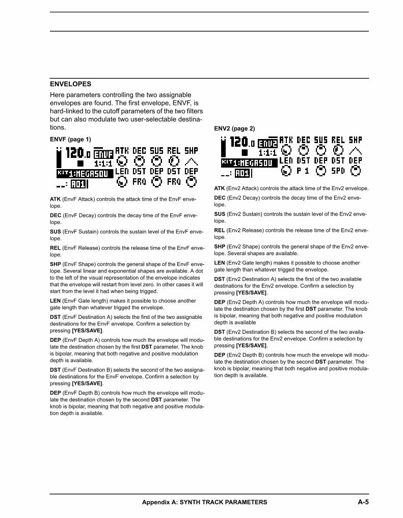
Appendix A: SYNTH TRACK PARAMETERS A-5
ENVELOPESHere parameters controlling the two assignable envelopes are found. The first envelope, ENVF, is hard-linked to the cutoff parameters of the two filters but can also modulate two user-selectable destina-tions.
ENVF (page 1)
ATK (EnvF Attack) controls the attack time of the EnvF enve-lope.
DEC (EnvF Decay) controls the decay time of the EnvF enve-lope.
SUS (EnvF Sustain) controls the sustain level of the EnvF enve-lope.
REL (EnvF Release) controls the release time of the EnvF enve-lope.
SHP (EnvF Shape) controls the general shape of the EnvF enve-lope. Several linear and exponential shapes are available. A dot to the left of the visual representation of the envelope indicates that the envelope will restart from level zero. In other cases it will start from the level it had when being trigged.
LEN (EnvF Gate length) makes it possible to choose another gate length than whatever trigged the envelope.
DST (EnvF Destination A) selects the first of the two assignable destinations for the EnvF envelope. Confirm a selection by pressing [YES/SAVE].
DEP (EnvF Depth A) controls how much the envelope will modu-late the destination chosen by the first DST parameter. The knob is bipolar, meaning that both negative and positive modulation depth is available.
DST (EnvF Destination B) selects the second of the two assigna-ble destinations for the EnvF envelope. Confirm a selection by pressing [YES/SAVE].
DEP (EnvF Depth B) controls how much the envelope will modu-late the destination chosen by the second DST parameter. The knob is bipolar, meaning that both negative and positive modula-tion depth is available.
ENV2 (page 2)
ATK (Env2 Attack) controls the attack time of the Env2 envelope.
DEC (Env2 Decay) controls the decay time of the Env2 enve-lope.
SUS (Env2 Sustain) controls the sustain level of the Env2 enve-lope.
REL (Env2 Release) controls the release time of the Env2 enve-lope.
SHP (Env2 Shape) controls the general shape of the Env2 enve-lope. Several shapes are available.
LEN (Env2 Gate length) makes it possible to choose another gate length than whatever trigged the envelope.
DST (Env2 Destination A) selects the first of the two available destinations for the Env2 envelope. Confirm a selection by pressing [YES/SAVE].
DEP (Env2 Depth A) controls how much the envelope will modu-late the destination chosen by the first DST parameter. The knob is bipolar, meaning that both negative and positive modulation depth is available
DST (Env2 Destination B) selects the second of the two availa-ble destinations for the Env2 envelope. Confirm a selection by pressing [YES/SAVE].
DEP (Env2 Depth B) controls how much the envelope will modu-late the destination chosen by the second DST parameter. The knob is bipolar, meaning that both negative and positive modula-tion depth is available.

A-6 Appendix A: SYNTH TRACK PARAMETERS
LFOThe two track LFOs can be used to modulate the other synth track parameters.
LFO1 (page 1)
SPD (LFO1 Speed) controls the speed of LFO1. It is synced to the BPM. For LFO1 to be synced to straight beats, try settings of 16, 32 or 64. The value is bi-polar, meaning the LFO shape can be played backwards by using negative values.
MUL (LFO1 Multiplier) multiplies the SPD parameter by the set factor.
FAD (LFO1 Fade In/Out) offers the possibility to fade in/out the LFO modulation. Positive values give a fade-out, negative values give a fade-in. A mid position (0) will result in no fade in/out.
SPH (LFO1 Start Phase) controls where in the waveform the LFO1 will start when being trigged.
MOD (LFO1 Trig Mode) controls how the LFO1 will react when a note is played. Five settings exist.
• FRE is the default free-running mode. It makes LFO1 run continuously, never restarting or stopping.
• TRG makes LFO1 restart when a note is played.
• HLD makes LFO1 run free in the background, but when a note is played the output LFO1 level is latched and held still until the next note is played.
• ONE will make LFO1 start from the beginning when a note is played, run for one cycle and then stop. This makes it function similarly to an envelope.
• HLF will make LFO1 start from the beginning when a note is played, run for half a cycle and then stop.
WAV (LFO1 Waveform) controls the LFO1 waveform.
DST (LFO1 Destination A) selects the first of the two available destinations for LFO1. Confirm a selection by pressing [YES/SAVE].
DEP (LFO1 Depth A) controls how much LFO1 will modulate the destination chosen by the first DST parameter. The knob is bipo-lar, meaning that both negative and positive modulation depth is available.
DST (LFO1 Destination B) selects the second of the two availa-ble destinations for LFO1. Confirm a selection by pressing [YES/SAVE].
DEP (LFO1 Depth B) controls how much the LFO1 will modulate the destination chosen by the second DST parameter. The knob
is bipolar, meaning that both negative and positive modulation depth is available.
LFO2 (page 2)
SPD (LFO2 Speed) controls the speed of LFO2. It is synced to the BPM. For LFO2 to be synced to straight beats, try settings of 16, 32 or 64. The value is bi-polar, meaning the LFO shape can be played backwards by using negative values.
MUL (LFO2 Multiplier) multiplies the SPD parameter by the set factor.
FAD (LFO2 Fade In/Out) offers the possibility to fade in/out the LFO modulation. Positive values give a fade-out, negative values give a fade-in. A mid position (0) will result in no fade in/out.
SPH (LFO2 Start Phase) controls where in the waveform the LFO2 will start when being trigged.
MOD (LFO2 Trig Mode) controls how the LFO2 will react when a note is played. Five settings exist.
• FRE is the default free-running mode. It makes LFO2 run continuously, never restarting or stopping.
• TRG makes LFO2 restart when a note is played.
• HLD makes LFO2 run free in the background, but when a note is played the output LFO2 level is latched and held still until the next note is played.
• ONE will make LFO2 start from the beginning when a note is played, run for one cycle and then stop. This makes it function similarly to an envelope.
• HLF will make LFO2 start from the beginning when a note is played, run for half a cycle and then stop.
WAV (LFO2 Waveform) controls the LFO2 waveform.
DST (LFO1 Destination A) selects the first of the two available destinations for LFO2. Confirm a selection by pressing [YES/SAVE].
DEP (LFO2 Depth A) controls how much LFO2 will modulate the destination chosen by the first DST parameter. The knob is bipo-lar, meaning that both negative and positive modulation depth is available.
DST (LFO2 Destination B) selects the second of the two availa-ble destinations for LFO2. Confirm a selection by pressing [YES/SAVE].
DEP (LFO2 Depth B) controls how much the LFO2 will modulate the destination chosen by the second DST parameter. The knob

Appendix B: FX TRACK PARAMETERS B-1
Appendix B: FX TRACK PARAMETERSIn this appendix, the parameters of the external input page and the three send effects are explained.
EXT
CHO (Ext. L Chorus) controls how much of the signal coming from the left external input that will be sent to the Wideshift Cho-rus effect.
DEL (Ext. L Delay) controls how much of the signal coming from the left external input that will be sent to the Saturator Delay effect.
REV (Ext. L Reverb) controls how much of the signal coming from the left external input that will be sent to the Supervoid reverb effect.
PAN (Ext. L Pan) positions the signal coming from the left exter-nal input in the stereo field. When using the audio inputs as a stereo pair, it would be normal to pan this signal hard left.
VOL (Ext. L Volume) adjusts the volume of the signal coming from the left external input.
CHO (Ext. R Chorus) controls how much of the signal coming from the right external input that will be sent to the Wideshift Chorus effect.
DEL (Ext. R Delay) controls how much of the signal coming from the right external input that will be sent to the Saturator Delay effect.
REV (Ext. R Reverb) controls how much of the signal coming from the right external input that will be sent to the Supervoid reverb effect.
PAN (Ext. R Pan) positions the signal coming from the right external input in the stereo field. When using the audio inputs as a stereo pair, it would be normal to pan this signal hard right.
VOL (Ext. R Volume) adjusts the volume of the signal coming from the right external input.
EXTERNAL INThe EXT IN page controls the signal path from the two audio inputs to the main mixer. These external signals can be routed to the effects and panned just like the four synth tracks.
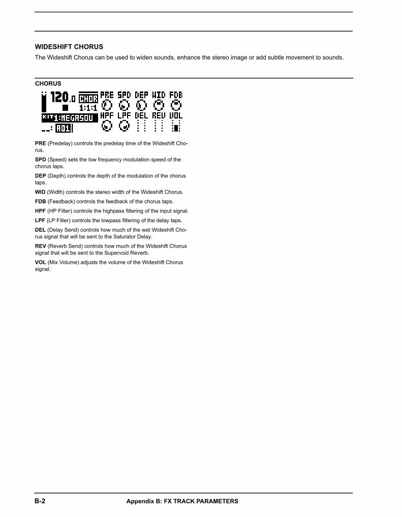
B-2 Appendix B: FX TRACK PARAMETERS
CHORUS
PRE (Predelay) controls the predelay time of the Wideshift Cho-rus.
SPD (Speed) sets the low frequency modulation speed of the chorus taps.
DEP (Depth) controls the depth of the modulation of the chorus taps.
WID (Width) controls the stereo width of the Wideshift Chorus.
FDB (Feedback) controls the feedback of the chorus taps.
HPF (HP Filter) controls the highpass filtering of the input signal.
LPF (LP Filter) controls the lowpass filtering of the delay taps.
DEL (Delay Send) controls how much of the wet Wideshift Cho-rus signal that will be sent to the Saturator Delay.
REV (Reverb Send) controls how much of the Wideshift Chorus signal that will be sent to the Supervoid Reverb.
VOL (Mix Volume) adjusts the volume of the Wideshift Chorus signal.
WIDESHIFT CHORUSThe Wideshift Chorus can be used to widen sounds, enhance the stereo image or add subtle movement to sounds.

Appendix B: FX TRACK PARAMETERS B-3
DELAY
TIM (Time) sets the delay time. It is relative to the current BPM and is measured in 128th notes. For instance, a setting of 32 equals a one beat delay (four 1/16th notes).
X (Pingpong) controls how the delay signal will act in the stereo field.
• 0 makes it possible to manually situate the delay signal in the stereo field. The WID parameter controls the placement.
• 1 will make the delay signal alternate between left and right pan positions. The WID parameter controls the amount of panning.
WID (Width) controls the stereo width or placement of the delay signal.
FDB (Feedback) controls how much of the delay output that will be fed back into the input of the delay. With higher parameter settings, infinite and/or swelling delays are possible to achieve. Please be aware that high feedback can lead to a very loud sig-nal, and that the OVR parameter can further increase the feed-back.
HPF (HP Filter) controls the highpass filtering of the delay taps.
LPF (LP Filter) controls the lowpass filtering of the delay taps.
OVR (Overdrive) controls how much the delay signal will be overdriven. Please note that higher settings will affect the feed-back of the delay.
REV (Reverb Send) controls how much of the Saturator Delay signal that will be sent to the Supervoid Reverb.
VOL (Mix Volume) adjusts the volume of the Saturator Delay sig-nal.
SATURATOR DELAYThe Saturator Delay adds an echo-like effect to the audio. Thanks to the special features of this effect, it can also be used to subtly warm or severely distort the delay signal.
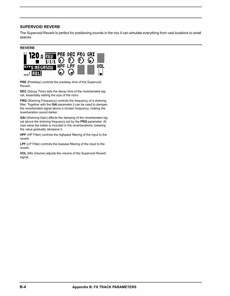
B-4 Appendix B: FX TRACK PARAMETERS
REVERB
PRE (Predelay) controls the predelay time of the Supervoid Reverb.
DEC (Decay Time) sets the decay time of the reverberated sig-nal, essentially setting the size of the room.
FRQ (Shelving Frequency) controls the frequency of a shelving filter. Together with the GAI parameter it can be used to dampen the reverberated signal above a chosen frequency, making the reverberation sound darker.
GAI (Shelving Gain) affects the damping of the reverberated sig-nal above the shelving frequency set by the FRQ parameter. At max value the treble is included in the reverberations; lowering the value gradually dampens it.
HPF (HP Filter) controls the highpass filtering of the input to the reverb.
LPF (LP Filter) controls the lowpass filtering of the input to the reverb.
VOL (Mix Volume) adjusts the volume of the Supervoid Reverb signal.
SUPERVOID REVERBThe Supervoid Reverb is perfect for positioning sounds in the mix.It can simulate everything from vast locations to small spaces.

Appendix B: FX TRACK PARAMETERS B-5
LFO1 (page 1)
SPD (LFO1 Speed) controls the speed of LFO1. It is synced to the BPM. For LFO1 to be synced to straight beats, try settings of 16, 32 or 64. The value is bi-polar, meaning the LFO shape can be played backwards by using negative values.
MUL (LFO1 Multiplier) multiplies the SPD parameter by the set factor.
FAD (LFO1 Fade In/Out) offers the possibility to fade in/out the LFO modulation. Positive values give a fade-out, negative values give a fade-in. A mid position (0) will result in no fade in/out.
SPH (LFO1 Start Phase) controls where in the waveform the LFO1 should start when being trigged.
MOD (LFO1 Trig Mode) controls how the LFO1 should react when a note is played. Five settings exist.
• FRE is the default free-running mode. It makes LFO1 run continuously, never restarting or stopping.
• TRG makes LFO1 restart when a note is played.
• HLD makes LFO1 run free in the background, but when a note is played the output LFO1 level is latched and held still until the next note is played.
• ONE will make LFO1 start from the beginning when a note is played, run for one cycle and then stop. This makes it function similarly to an envelope.
• HLF will make LFO1 start from the beginning when a note is played, run for half a cycle and then stop.
WAV (LFO1 Waveform) controls the LFO1 waveform.
DST (LFO1 Destination A) selects the first of the two available destinations for LFO1. Confirm a selection by pressing [YES/SAVE].
DEP (LFO1 Depth A) controls how much LFO1 will modulate the destination chosen by the first DST parameter. The knob is bipo-lar, meaning that both negative and positive modulation depth is available.
DST (LFO1 Destination B) selects the second of the two availa-ble destinations for LFO1. Confirm a selection by pressing [YES/SAVE].
DEP (LFO1 Depth B) controls how much the LFO1 will modulate the destination chosen by the second DST parameter. The knob is bipolar, meaning that both negative and positive modulation depth is available.
LFO2 (page 2)
SPD (LFO2 Speed) controls the speed of LFO2. It is synced to the BPM. For LFO2 to be synced to straight beats, try settings of 16, 32 or 64. The value is bi-polar, meaning the LFO shape can be played backwards by using negative values.
MUL (LFO2 Multiplier) multiplies the SPD parameter by the set factor.
FAD (LFO2 Fade In/Out) offers the possibility to fade in/out the LFO modulation. Positive values give a fade-out, negative values give a fade-in. A mid position (0) will result in no fade in/out.
SPH (LFO2 Start Phase) controls where in the waveform the LFO2 should start when being trigged.
MOD (LFO2 Trig Mode) controls how the LFO2 should react when a note is played. Five settings exist.
• FRE is the default free-running mode. It makes LFO2 run continuously, never restarting or stopping.
• TRG makes LFO2 restart when a note is played.
• HLD makes LFO2 run free in the background, but when a note is played the output LFO2 level is latched and held still until the next note is played.
• ONE will make LFO2 start from the beginning when a note is played, run for one cycle and then stop. This makes it function similarly to an envelope.
• HLF will make LFO2 start from the beginning when a note is played, run for half a cycle and then stop.
WAV (LFO2 Waveform) controls the LFO2 waveform.
DST (LFO1 Destination A) selects the first of the two available destinations for LFO2. Confirm a selection by pressing [YES/SAVE].
DEP (LFO2 Depth A) controls how much LFO2 will modulate the destination chosen by the first DST parameter. The knob is bipo-lar, meaning that both negative and positive modulation depth is available.
DST (LFO2 Destination B) selects the second of the two availa-ble destinations for LFO2. Confirm a selection by pressing [YES/SAVE].
DEP (LFO2 Depth B) controls how much the LFO2 will modulatethe destination chosen by the second DST parameter. The knobis bipolar, meaning that both negative and positive modulationdepth is available.
FX LFOThe FX LFO menu consists of two LFOs dedicated to modulating FX track parameters.

B-6 Appendix B: FX TRACK PARAMETERS

Appendix C: CV TRACK PARAMETERS C-1
Appendix C: CV TRACK PARAMETERSIn this appendix, the CV/Gate track parameters are explained.
CV A-DThe CV A-D pages control the signals sent from the 2 dual CV/Gate outputs. Depending on the CV type chosen in the CV CONFIG menu, the available parameters will change.
CV (GROUNDED)
No parameters available. The CV output will not send any signal.
CV (PITCH V/OCT)
TUN (Coarse Tune) sets the coarse tuning of the CV in semi-tones.
FIN (Fine Tune) sets the fine tuning of the CV.
BND (Bend Depth) controls the bend depth. The higher the set-ting, the more the pitch of a trigged note will be offset.
SLI (Note Slide time) sets the CV control of the slide time of note slides.
SRC (Source Track) selects the track whose notes should be used for sending CV signals. The CV track, FX track and synth tracks 1-4 can be used as source.
A note about the LCD graphics: The audio plug graphics in the CV A-D PARAMETER pages flashes, indicating whether tip or ring of the audio cable plug is used for sending the CV/Gate sig-nals the active PARAMETER page controls.
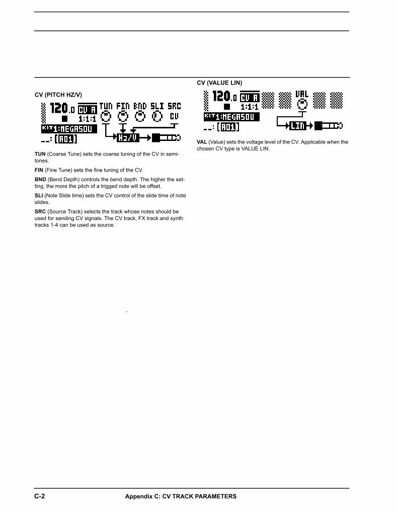
C-2 Appendix C: CV TRACK PARAMETERS
CV (PITCH HZ/V)
TUN (Coarse Tune) sets the coarse tuning of the CV in semi-tones.
FIN (Fine Tune) sets the fine tuning of the CV.
BND (Bend Depth) controls the bend depth. The higher the set-ting, the more the pitch of a trigged note will be offset.
SLI (Note Slide time) sets the CV control of the slide time of note slides.
SRC (Source Track) selects the track whose notes should be used for sending CV signals. The CV track, FX track and synth tracks 1-4 can be used as source.
.
CV (VALUE LIN)
VAL (Value) sets the voltage level of the CV. Applicable when the chosen CV type is VALUE LIN.

Appendix C: CV TRACK PARAMETERS C-3
CV (TRIG)
SRC (Source Track) selects the track whose notes should be used for sending trig signals. The CV track, FX track and synth tracks 1-4 can be used as source.
CV (GATE)
SRC (Source Track) selects the track whose notes should be used for sending gate signals. The CV track, FX track and synth tracks 1-4 can be used as source.

C-4 Appendix C: CV TRACK PARAMETERS
CV (CLOCK)
CLK (Clock Division) sets the clock division. This setting relates to the BPM of the sequencer.

Appendix C: CV TRACK PARAMETERS C-5
CV ENVELOPESHere parameters controlling the two assignable CV envelopes are found. The CV envelopes can modulate parameters found on the CV track. They can also be sent to the CV/Gate outputs, by setting up a CV channel's type as VALUE LIN.
ENV1 (page 1)
ATK (Env1 Attack) controls the attack time of the Env1 envelope.
DEC (Env1 Decay) controls the decay time of the EnvF enve-lope.
SUS (Env1 Sustain) controls the sustain level of the EnvF enve-lope.
REL (Env1 Release) controls the release time of the EnvF enve-lope.
SHP (Env1 Shape) controls the general shape of the Env1 enve-lope. Several linear and exponential shapes are available. A dot to the left of the visual representation of the envelope indicates that the envelope will restart from level zero. In other cases it will start from the level it had when being trigged.
LEN (Env1 Gate length) makes it possible to choose another gate length than whatever trigged the envelope.
DST (Env1 Destination A) selects the first of the two available destinations for the EnvF envelope. Confirm a selection by pressing [YES/SAVE].
DEP (Env1 Depth A) controls how much the envelope will modu-late the destination chosen by the first DST parameter. The knob is bipolar, meaning that both negative and positive modulation depth is available.
DST (Env1 Destination B) selects the second of the two availa-ble destinations for the EnvF envelope. Confirm a selection by pressing [YES/SAVE].
DEP (Env1 Depth B) controls how much the envelope will modu-late the destination chosen by the second DST parameter. The knob is bipolar, meaning that both negative and positive modula-tion depth is available.
ENV2 (page 2)
ATK (Env2 Attack) controls the attack time of the Env2 envelope.
DEC (Env2 Decay) controls the decay time of the Env2 enve-lope.
SUS (Env2 Sustain) controls the sustain level of the Env2 enve-lope.
REL (Env2 Release) controls the release time of the Env2 enve-lope.
SHP (Env2 Shape) controls the general shape of the Env2 enve-lope. Several shapes are available.
LEN (Env2 Gate length) makes it possible to choose another gate length than whatever trigged the envelope.
DST (Env2 Destination A) selects the first of the two available destinations for the Env2 envelope. Confirm a selection by pressing [YES/SAVE].
DEP (Env2 Depth A) controls how much the envelope will modu-late the destination chosen by the first DST parameter. The knob is bipolar, meaning that both negative and positive modulation depth is available
DST (Env2 Destination B) selects the second of the two availa-ble destinations for the Env2 envelope. Confirm a selection by pressing [YES/SAVE].
DEP (Env2 Depth B) controls how much the envelope will modu-late the destination chosen by the second DST parameter. The knob is bipolar, meaning that both negative and positive modula-tion depth is available.
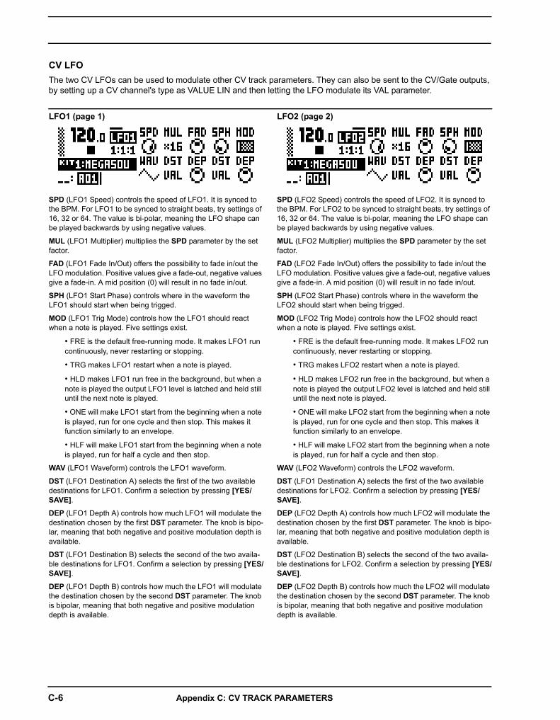
C-6 Appendix C: CV TRACK PARAMETERS
LFO1 (page 1)
SPD (LFO1 Speed) controls the speed of LFO1. It is synced to the BPM. For LFO1 to be synced to straight beats, try settings of 16, 32 or 64. The value is bi-polar, meaning the LFO shape can be played backwards by using negative values.
MUL (LFO1 Multiplier) multiplies the SPD parameter by the set factor.
FAD (LFO1 Fade In/Out) offers the possibility to fade in/out the LFO modulation. Positive values give a fade-out, negative values give a fade-in. A mid position (0) will result in no fade in/out.
SPH (LFO1 Start Phase) controls where in the waveform the LFO1 should start when being trigged.
MOD (LFO1 Trig Mode) controls how the LFO1 should react when a note is played. Five settings exist.
• FRE is the default free-running mode. It makes LFO1 run continuously, never restarting or stopping.
• TRG makes LFO1 restart when a note is played.
• HLD makes LFO1 run free in the background, but when a note is played the output LFO1 level is latched and held still until the next note is played.
• ONE will make LFO1 start from the beginning when a note is played, run for one cycle and then stop. This makes it function similarly to an envelope.
• HLF will make LFO1 start from the beginning when a note is played, run for half a cycle and then stop.
WAV (LFO1 Waveform) controls the LFO1 waveform.
DST (LFO1 Destination A) selects the first of the two available destinations for LFO1. Confirm a selection by pressing [YES/SAVE].
DEP (LFO1 Depth A) controls how much LFO1 will modulate the destination chosen by the first DST parameter. The knob is bipo-lar, meaning that both negative and positive modulation depth is available.
DST (LFO1 Destination B) selects the second of the two availa-ble destinations for LFO1. Confirm a selection by pressing [YES/SAVE].
DEP (LFO1 Depth B) controls how much the LFO1 will modulate the destination chosen by the second DST parameter. The knob is bipolar, meaning that both negative and positive modulation depth is available.
LFO2 (page 2)
SPD (LFO2 Speed) controls the speed of LFO2. It is synced to the BPM. For LFO2 to be synced to straight beats, try settings of 16, 32 or 64. The value is bi-polar, meaning the LFO shape can be played backwards by using negative values.
MUL (LFO2 Multiplier) multiplies the SPD parameter by the set factor.
FAD (LFO2 Fade In/Out) offers the possibility to fade in/out the LFO modulation. Positive values give a fade-out, negative values give a fade-in. A mid position (0) will result in no fade in/out.
SPH (LFO2 Start Phase) controls where in the waveform the LFO2 should start when being trigged.
MOD (LFO2 Trig Mode) controls how the LFO2 should react when a note is played. Five settings exist.
• FRE is the default free-running mode. It makes LFO2 run continuously, never restarting or stopping.
• TRG makes LFO2 restart when a note is played.
• HLD makes LFO2 run free in the background, but when a note is played the output LFO2 level is latched and held still until the next note is played.
• ONE will make LFO2 start from the beginning when a note is played, run for one cycle and then stop. This makes it function similarly to an envelope.
• HLF will make LFO2 start from the beginning when a note is played, run for half a cycle and then stop.
WAV (LFO2 Waveform) controls the LFO2 waveform.
DST (LFO1 Destination A) selects the first of the two available destinations for LFO2. Confirm a selection by pressing [YES/SAVE].
DEP (LFO2 Depth A) controls how much LFO2 will modulate the destination chosen by the first DST parameter. The knob is bipo-lar, meaning that both negative and positive modulation depth is available.
DST (LFO2 Destination B) selects the second of the two availa-ble destinations for LFO2. Confirm a selection by pressing [YES/SAVE].
DEP (LFO2 Depth B) controls how much the LFO2 will modulate the destination chosen by the second DST parameter. The knob is bipolar, meaning that both negative and positive modulation depth is available.
CV LFOThe two CV LFOs can be used to modulate other CV track parameters. They can also be sent to the CV/Gate outputs, by setting up a CV channel's type as VALUE LIN and then letting the LFO modulate its VAL parameter.

D-1
Appendix D: MIDIIn this appendix, the MIDI CC and NRPN implementation is covered.
PERFORMANCE PARAMETERSThe following messages affect the performance parameters on all tracks. They are also sent when adjusting the knobs controlling the parameters.
MODULATION PARAMETERSThe following CC messages affect modulation parameters. Which parameters they will in turn affect are set in the SOUND SETTINGS menu (where modulation parameters for velocity, pitch bend and aftertouch can also be found), covered on page 26.
PERFORMANCE NRPNParameter Encoder NRPN MSB NRPN LSB Data Range MSB Data Range LSB
Performance Parameter A A 0 0 0-127 -
Performance Parameter B B 0 1 0-127 -
Performance Parameter C C 0 2 0-127 -
Performance Parameter D D 0 3 0-127 -
Performance Parameter E E 0 4 0-127 -
Performance Parameter F F 0 5 0-127 -
Performance Parameter G G 0 6 0-127 -
Performance Parameter H H 0 7 0-127 -
Performance Parameter I I 0 8 0-127 -
Performance Parameter J J 0 9 0-127 -
PERFORMANCE CCParameter Encoder CC MSB CC LSB Data Range MSB Data Range LSB
Performance Parameter A A 3 - 0-127 -
Performance Parameter B B 4 - 0-127 -
Performance Parameter C C 8 - 0-127 -
Performance Parameter D D 9 - 0-127 -
Performance Parameter E E 11 - 0-127 -
Performance Parameter F F 64 - 0-127 -
Performance Parameter G G 65 - 0-127 -
Performance Parameter H H 66 - 0-127 -
Performance Parameter I I 67 - 0-127 -
Performance Parameter J J 68 - 0-127 -
MODULATION CCParameter Encoder CC MSB CC LSB Data Range MSB Data Range LSB
Modwheel - 1 33 0-127 0-127
Breath Controller - 2 34 0-127 0-127
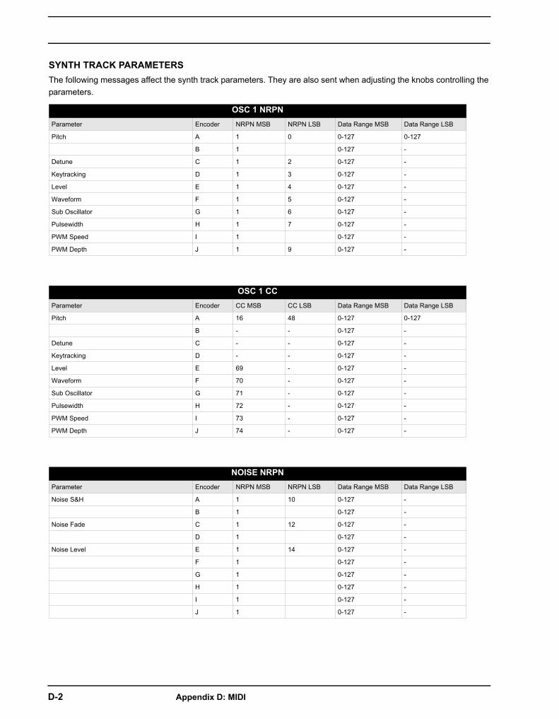
D-2 Appendix D: MIDI
SYNTH TRACK PARAMETERSThe following messages affect the synth track parameters. They are also sent when adjusting the knobs controlling the parameters.
OSC 1 NRPNParameter Encoder NRPN MSB NRPN LSB Data Range MSB Data Range LSB
Pitch A 1 0 0-127 0-127
B 1 0-127 -
Detune C 1 2 0-127 -
Keytracking D 1 3 0-127 -
Level E 1 4 0-127 -
Waveform F 1 5 0-127 -
Sub Oscillator G 1 6 0-127 -
Pulsewidth H 1 7 0-127 -
PWM Speed I 1 0-127 -
PWM Depth J 1 9 0-127 -
OSC 1 CCParameter Encoder CC MSB CC LSB Data Range MSB Data Range LSB
Pitch A 16 48 0-127 0-127
B - - 0-127 -
Detune C - - 0-127 -
Keytracking D - - 0-127 -
Level E 69 - 0-127 -
Waveform F 70 - 0-127 -
Sub Oscillator G 71 - 0-127 -
Pulsewidth H 72 - 0-127 -
PWM Speed I 73 - 0-127 -
PWM Depth J 74 - 0-127 -
NOISE NRPNParameter Encoder NRPN MSB NRPN LSB Data Range MSB Data Range LSB
Noise S&H A 1 10 0-127 -
B 1 0-127 -
Noise Fade C 1 12 0-127 -
D 1 0-127 -
Noise Level E 1 14 0-127 -
F 1 0-127 -
G 1 0-127 -
H 1 0-127 -
I 1 0-127 -
J 1 0-127 -

Appendix D: MIDI D-3
NOISE CCParameter Encoder CC MSB CC LSB Data Range MSB Data Range LSB
Noise S&H A 75 - 0-127 -
B - - 0-127 -
Noise Fade C 76 - 0-127 -
D - - 0-127 -
Noise Level E 77 - 0-127 -
F - - 0-127 -
G - - 0-127 -
H - - 0-127 -
I - - 0-127 -
J - - 0-127 -
OSC 2 NRPNParameter Encoder NRPN MSB NRPN LSB Data Range MSB Data Range LSB
Pitch A 1 20 0-127 0-127
B 1 0-127 -
Detune C 1 22 0-127 -
Keytracking D 1 23 0-127 -
Level E 1 24 0-127 -
Waveform F 1 25 0-127 -
Sub Oscillator G 1 26 0-127 -
Pulsewidth H 1 27 0-127 -
PWM Speed I 1 0-127 -
PWM Depth J 1 29 0-127 -
OSC 2 CCParameter Encoder CC MSB CC LSB Data Range MSB Data Range LSB
Pitch A 17 49 0-127 0-127
B - - 0-127 -
Detune C - - 0-127 -
Keytracking D - - 0-127 -
Level E 78 - 0-127 -
Waveform F 79 - 0-127 -
Sub Oscillator G 80 - 0-127 -
Pulsewidth H 81 - 0-127 -
PWM Speed I 82 - 0-127 -
PWM Depth J 83 - 0-127 -
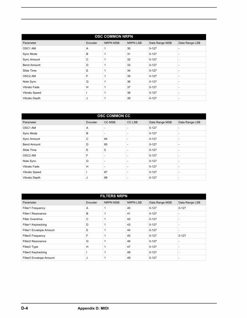
D-4 Appendix D: MIDI
OSC COMMON NRPNParameter Encoder NRPN MSB NRPN LSB Data Range MSB Data Range LSB
OSC1 AM A 1 30 0-127 -
Sync Mode B 1 31 0-127 -
Sync Amount C 1 32 0-127 -
Bend Amount D 1 33 0-127 -
Slide Time E 1 34 0-127 -
OSC2 AM F 1 35 0-127 -
Note Sync G 1 36 0-127 -
Vibrato Fade H 1 37 0-127 -
Vibrato Speed I 1 38 0-127 -
Vibrato Depth J 1 39 0-127 -
OSC COMMON CCParameter Encoder CC MSB CC LSB Data Range MSB Data Range LSB
OSC1 AM A - - 0-127 -
Sync Mode B - - 0-127 -
Sync Amount C 84 - 0-127 -
Bend Amount D 85 - 0-127 -
Slide Time E 5 - 0-127 -
OSC2 AM F - - 0-127 -
Note Sync G - - 0-127 -
Vibrato Fade H - - 0-127 -
Vibrato Speed I 87 - 0-127 -
Vibrato Depth J 88 - 0-127 -
FILTERS NRPNParameter Encoder NRPN MSB NRPN LSB Data Range MSB Data Range LSB
Filter1 Frequency A 1 40 0-127 0-127
Filter1 Resonance B 1 41 0-127 -
Filter Overdrive C 1 42 0-127 -
Filter1 Keytracking D 1 43 0-127 -
Filter1 Envelope Amount E 1 44 0-127 -
Filter2 Frequency F 1 45 0-127 0-127
Filter2 Resonance G 1 46 0-127 -
Filter2 Type H 1 47 0-127 -
Filter2 Keytracking I 1 48 0-127 -
Filter2 Envelope Amount J 1 49 0-127 -

Appendix D: MIDI D-5
FILTERS CCParameter Encoder CC MSB CC LSB Data Range MSB Data Range LSB
Filter1 Frequency A 18 50 0-127 0-127
Filter1 Resonance B 89 - 0-127 -
Filter Overdrive C - - 0-127 -
Filter1 Keytracking D - - 0-127 -
Filter1 Envelope Amount E 102 - 0-127 -
Filter2 Frequency F 19 51 0-127 0-127
Filter2 Resonance G 90 - 0-127 -
Filter2 Type H - - 0-127 -
Filter2 Keytracking I - - 0-127 -
Filter2 Envelope Amount J 103 - 0-127 -
AMP NRPNParameter Encoder NRPN MSB NRPN LSB Data Range MSB Data Range LSB
EnvA Attack Time A 1 50 0-127 -
EnvA Decay Time B 1 51 0-127 -
EnvA Sustain Level C 1 52 0-127 -
EnvA Release Time D 1 53 0-127 -
EnvA Env Shape E 1 54 0-127 -
Chorus Send Level F 1 55 0-127 -
Delay Send Level G 1 56 0-127 -
Reverb Send Level H 1 57 0-127 -
Pan I 1 58 0-127 -
Volume J 1 59 0-127 -
AMP CCParameter Encoder CC MSB CC LSB Data Range MSB Data Range LSB
EnvA Attack Time A 104 - 0-127 -
EnvA Decay Time B 105 - 0-127 -
EnvA Sustain Level C 106 - 0-127 -
EnvA Release Time D 107 - 0-127 -
EnvA Env Shape E - - 0-127 -
Chorus Send Level F 91 - 0-127 -
Delay Send Level G 92 - 0-127 -
Reverb Send Level H 93 - 0-127 -
Pan I 10 - 0-127 -
Volume J 7 - 0-127 -

D-6 Appendix D: MIDI
ENVF NRPNParameter Encoder NRPN MSB NRPN LSB Data Range MSB Data Range LSB
EnvF Attack Time A 1 60 0-127 -
EnvF Decay Time B 1 61 0-127 -
EnvF Sustain Level C 1 62 0-127 -
EnvF Release Time D 1 63 0-127 -
EnvF Env Shape E 1 64 0-127 -
EnvF Gate Length F 1 65 0-127 -
EnvF Destination A G 1 66 0-127 -
EnvF Depth A H 1 67 0-127 0-127
EnvF Destination B I 1 68 0-127 -
EnvF Depth B J 1 69 0-127 0-127
ENVF CCParameter Encoder CC MSB CC LSB Data Range MSB Data Range LSB
EnvF Attack Time A 108 - 0-127 -
EnvF Decay Time B 109 - 0-127 -
EnvF Sustain Level C 110 - 0-127 -
EnvF Release Time D 111 - 0-127 -
EnvF Env Shape E - - 0-127 -
EnvF Gate Length F - - 0-127 -
EnvF Destination A G - - 0-127 -
EnvF Depth A H 20 52 0-127 0-127
EnvF Destination B I - - 0-127 -
EnvF Depth B J 21 53 0-127 0-127
ENV2 NRPNParameter Encoder NRPN MSB NRPN LSB Data Range MSB Data Range LSB
Env2 Attack Time A 1 70 0-127 -
Env2 Decay Time B 1 71 0-127 -
Env2 Sustain Level C 1 72 0-127 -
Env2 Release Time D 1 73 0-127 -
Env2 Env Shape E 1 74 0-127 -
Env2 Gate Length F 1 75 0-127 -
Env2 Destination A G 1 76 0-127 -
Env2 Depth A H 1 77 0-127 0-127
Env2 Destination B I 1 78 0-127 -
Env2 Depth B J 1 79 0-127 0-127

Appendix D: MIDI D-7
ENV2 CCParameter Encoder CC MSB CC LSB Data Range MSB Data Range LSB
Env2 Attack Time A 112 - 0-127 -
Env2 Decay Time B 113 - 0-127 -
Env2 Sustain Level C 114 - 0-127 -
Env2 Release Time D 115 - 0-127 -
Env2 Env Shape E - - 0-127 -
Env2 Gate Length F - - 0-127 -
Env2 Destination A G - - 0-127 -
Env2 Depth A H 22 54 0-127 0-127
Env2 Destination B I - - 0-127 -
Env2 Depth B J 23 55 0-127 0-127
LFO1 NRPNParameter Encoder NRPN MSB NRPN LSB Data Range MSB Data Range LSB
LFO1 Speed A 1 80 0-127 -
LFO1 Speed Multiplier B 1 81 0-127 -
LFO1 Fade C 1 82 0-127 -
LFO1 Start Phase D 1 83 0-127 -
LFO1 Mode E 1 84 0-127 -
LFO1 Waveform F 1 85 0-127 -
LFO1 Destination A G 1 86 0-127 -
LFO1 Depth A H 1 87 0-127 0-127
LFO1 Destination B I 1 88 0-127 -
LFO1 Depth B J 1 89 0-127 0-127
LFO1 CCParameter Encoder CC MSB CC LSB Data Range MSB Data Range LSB
LFO1 Speed A 116 - 0-127 -
LFO1 Speed Multiplier B 117 - 0-127 -
LFO1 Fade C - - 0-127 -
LFO1 Start Phase D - - 0-127 -
LFO1 Mode E - - 0-127 -
LFO1 Waveform F - - 0-127 -
LFO1 Destination A G - - 0-127 -
LFO1 Depth A H 24 56 0-127 0-127
LFO1 Destination B I - - 0-127 -
LFO1 Depth B J 25 57 0-127 0-127

D-8 Appendix D: MIDI
LFO2 NRPNParameter Encoder NRPN MSB NRPN LSB Data Range MSB Data Range LSB
LFO2 Speed A 1 90 0-127 -
LFO2 Speed Multiplier B 1 91 0-127 -
LFO2 Fade C 1 92 0-127 -
LFO2 Start Phase D 1 93 0-127 -
LFO2 Mode E 1 94 0-127 -
LFO2 Waveform F 1 95 0-127 -
LFO2 Destination A G 1 96 0-127 -
LFO2 Depth A H 1 97 0-127 0-127
LFO2 Destination B I 1 98 0-127 -
LFO2 Depth B J 1 99 0-127 0-127
LFO2 CCParameter Encoder CC MSB CC LSB Data Range MSB Data Range LSB
LFO2 Speed A 118 - 0-127 -
LFO2 Speed Multiplier B 119 - 0-127 -
LFO2 Fade C - - 0-127 -
LFO2 Start Phase D - - 0-127 -
LFO2 Mode E - - 0-127 -
LFO2 Waveform F - - 0-127 -
LFO2 Destination A G - - 0-127 -
LFO2 Depth A H 26 58 0-127 0-127
LFO2 Destination B I - - 0-127 -
LFO2 Depth B J 27 59 0-127 0-127

Appendix D: MIDI D-9
FX TRACK PARAMETERSThe following messages affect the FX track parameters. They are also sent when adjusting the knobs controlling the parameters.
EXT INParameter Encoder NRPN MSB NRPN LSB Data Range MSB Data Range LSB
Ch1 Chorus Send A 2 0 0-127 -
Ch1 Delay Send B 2 1 0-127 -
Ch1 Reverb Send C 2 2 0-127 -
Ch1 Pan D 2 3 0-127 -
Ch1 Level E 2 4 0-127 -
Ch2 Chorus Send F 2 5 0-127 -
Ch2 Delay Send G 2 6 0-127 -
Ch2 Reverb Send H 2 7 0-127 -
Ch2 Pan I 2 8 0-127 -
Ch2 Level J 2 9 0-127 -
CHORUSParameter Encoder NRPN MSB NRPN LSB Data Range MSB Data Range LSB
Predelay A 2 40 0-127 -
Speed B 2 41 0-127 -
Depth C 2 42 0-127 -
Width D 2 43 0-127 -
Feedback E 2 44 0-127 -
HP Filter F 2 45 0-127 -
LP Filter G 2 46 0-127 -
Delay Send H 2 47 0-127 -
Reverb Send I 2 48 0-127 -
Send Level J 2 49 0-127 -
DELAYParameter Encoder NRPN MSB NRPN LSB Data Range MSB Data Range LSB
Time A 2 50 0-127 -
Mode B 2 51 0-127 -
C 2 52 0-127 -
Width D 2 53 0-127 -
Feedback E 2 54 0-127 -
HP Filter F 2 55 0-127 -
LP Filter G 2 56 0-127 -
Overdrive H 2 57 0-127 -
Reverb Send I 2 58 0-127 -
Send Level J 2 59 0-127 -
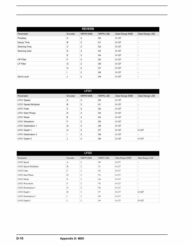
D-10 Appendix D: MIDI
REVERBParameter Encoder NRPN MSB NRPN LSB Data Range MSB Data Range LSB
Predelay A 2 60 0-127 -
Decay Time B 2 61 0-127 -
Shelving Freq C 2 62 0-127 -
Shelving Gain D 2 63 0-127 -
E 2 64 0-127 -
HP Filter F 2 65 0-127 -
LP Filter G 2 66 0-127 -
H 2 67 0-127 -
I 2 68 0-127 -
Send Level J 2 69 0-127 -
LFO1Parameter Encoder NRPN MSB NRPN LSB Data Range MSB Data Range LSB
LFO1 Speed A 2 80 0-127 -
LFO1 Speed Multiplier B 2 81 0-127 -
LFO1 Fade C 2 82 0-127 -
LFO1 Start Phase D 2 83 0-127 -
LFO1 Mode E 2 84 0-127 -
LFO1 Waveform F 2 85 0-127 -
LFO1 Destination 1 G 2 86 0-127 -
LFO1 Depth 1 H 2 87 0-127 0-127
LFO1 Destination 2 I 2 88 0-127 -
LFO1 Depth 2 J 2 89 0-127 0-127
LFO2Parameter Encoder NRPN MSB NRPN LSB Data Range MSB Data Range LSB
LFO2 Speed A 2 90 0-127 -
LFO2 Speed Multiplier B 2 91 0-127 -
LFO2 Fade C 2 92 0-127 -
LFO2 Start Phase D 2 93 0-127 -
LFO2 Mode E 2 94 0-127 -
LFO2 Waveform F 2 95 0-127 -
LFO2 Destination 1 G 2 96 0-127 -
LFO2 Depth 1 H 2 97 0-127 0-127
LFO2 Destination 2 I 2 98 0-127 -
LFO2 Depth 2 J 2 99 0-127 0-127
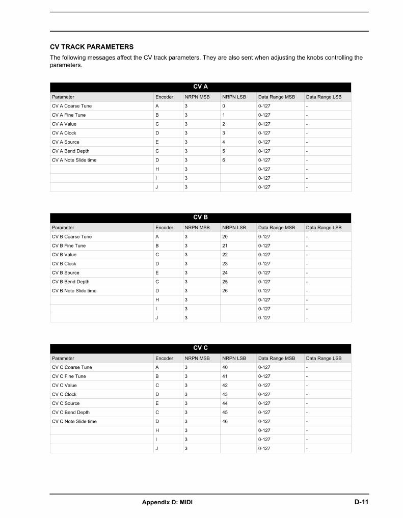
Appendix D: MIDI D-11
CV TRACK PARAMETERSThe following messages affect the CV track parameters. They are also sent when adjusting the knobs controlling the parameters.
CV AParameter Encoder NRPN MSB NRPN LSB Data Range MSB Data Range LSB
CV A Coarse Tune A 3 0 0-127 -
CV A Fine Tune B 3 1 0-127 -
CV A Value C 3 2 0-127 -
CV A Clock D 3 3 0-127 -
CV A Source E 3 4 0-127 -
CV A Bend Depth C 3 5 0-127 -
CV A Note Slide time D 3 6 0-127 -
H 3 0-127 -
I 3 0-127 -
J 3 0-127 -
CV BParameter Encoder NRPN MSB NRPN LSB Data Range MSB Data Range LSB
CV B Coarse Tune A 3 20 0-127 -
CV B Fine Tune B 3 21 0-127 -
CV B Value C 3 22 0-127 -
CV B Clock D 3 23 0-127 -
CV B Source E 3 24 0-127 -
CV B Bend Depth C 3 25 0-127 -
CV B Note Slide time D 3 26 0-127 -
H 3 0-127 -
I 3 0-127 -
J 3 0-127 -
CV CParameter Encoder NRPN MSB NRPN LSB Data Range MSB Data Range LSB
CV C Coarse Tune A 3 40 0-127 -
CV C Fine Tune B 3 41 0-127 -
CV C Value C 3 42 0-127 -
CV C Clock D 3 43 0-127 -
CV C Source E 3 44 0-127 -
CV C Bend Depth C 3 45 0-127 -
CV C Note Slide time D 3 46 0-127 -
H 3 0-127 -
I 3 0-127 -
J 3 0-127 -
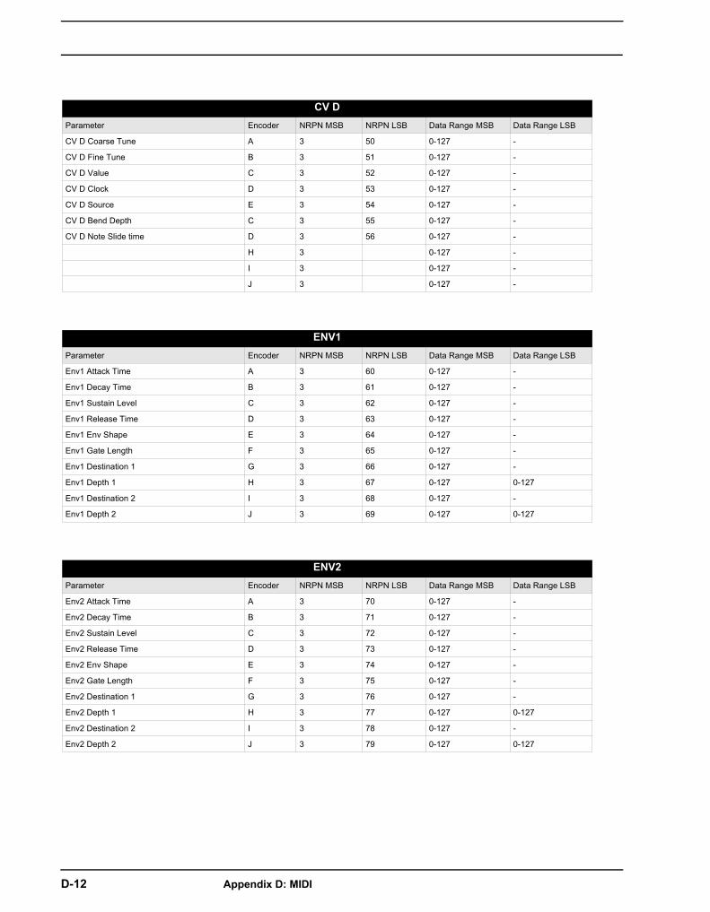
D-12 Appendix D: MIDI
CV DParameter Encoder NRPN MSB NRPN LSB Data Range MSB Data Range LSB
CV D Coarse Tune A 3 50 0-127 -
CV D Fine Tune B 3 51 0-127 -
CV D Value C 3 52 0-127 -
CV D Clock D 3 53 0-127 -
CV D Source E 3 54 0-127 -
CV D Bend Depth C 3 55 0-127 -
CV D Note Slide time D 3 56 0-127 -
H 3 0-127 -
I 3 0-127 -
J 3 0-127 -
ENV1Parameter Encoder NRPN MSB NRPN LSB Data Range MSB Data Range LSB
Env1 Attack Time A 3 60 0-127 -
Env1 Decay Time B 3 61 0-127 -
Env1 Sustain Level C 3 62 0-127 -
Env1 Release Time D 3 63 0-127 -
Env1 Env Shape E 3 64 0-127 -
Env1 Gate Length F 3 65 0-127 -
Env1 Destination 1 G 3 66 0-127 -
Env1 Depth 1 H 3 67 0-127 0-127
Env1 Destination 2 I 3 68 0-127 -
Env1 Depth 2 J 3 69 0-127 0-127
ENV2Parameter Encoder NRPN MSB NRPN LSB Data Range MSB Data Range LSB
Env2 Attack Time A 3 70 0-127 -
Env2 Decay Time B 3 71 0-127 -
Env2 Sustain Level C 3 72 0-127 -
Env2 Release Time D 3 73 0-127 -
Env2 Env Shape E 3 74 0-127 -
Env2 Gate Length F 3 75 0-127 -
Env2 Destination 1 G 3 76 0-127 -
Env2 Depth 1 H 3 77 0-127 0-127
Env2 Destination 2 I 3 78 0-127 -
Env2 Depth 2 J 3 79 0-127 0-127
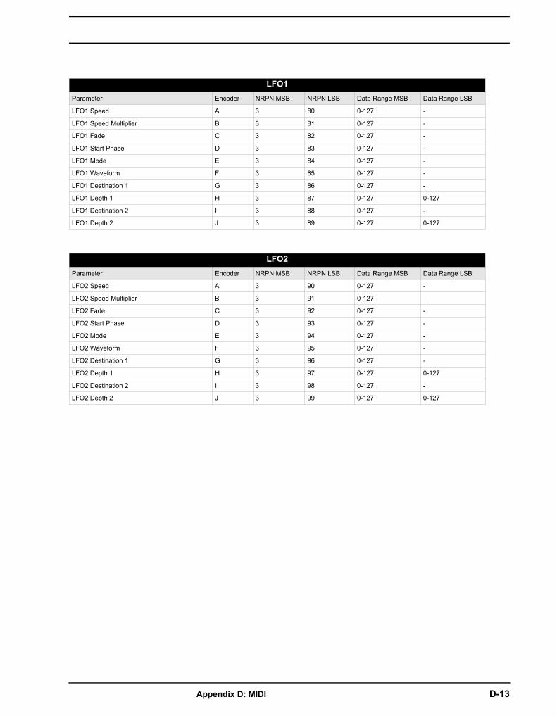
Appendix D: MIDI D-13
LFO1Parameter Encoder NRPN MSB NRPN LSB Data Range MSB Data Range LSB
LFO1 Speed A 3 80 0-127 -
LFO1 Speed Multiplier B 3 81 0-127 -
LFO1 Fade C 3 82 0-127 -
LFO1 Start Phase D 3 83 0-127 -
LFO1 Mode E 3 84 0-127 -
LFO1 Waveform F 3 85 0-127 -
LFO1 Destination 1 G 3 86 0-127 -
LFO1 Depth 1 H 3 87 0-127 0-127
LFO1 Destination 2 I 3 88 0-127 -
LFO1 Depth 2 J 3 89 0-127 0-127
LFO2Parameter Encoder NRPN MSB NRPN LSB Data Range MSB Data Range LSB
LFO2 Speed A 3 90 0-127 -
LFO2 Speed Multiplier B 3 91 0-127 -
LFO2 Fade C 3 92 0-127 -
LFO2 Start Phase D 3 93 0-127 -
LFO2 Mode E 3 94 0-127 -
LFO2 Waveform F 3 95 0-127 -
LFO2 Destination 1 G 3 96 0-127 -
LFO2 Depth 1 H 3 97 0-127 0-127
LFO2 Destination 2 I 3 98 0-127 -
LFO2 Depth 2 J 3 99 0-127 0-127

D-14 Appendix D: MIDI
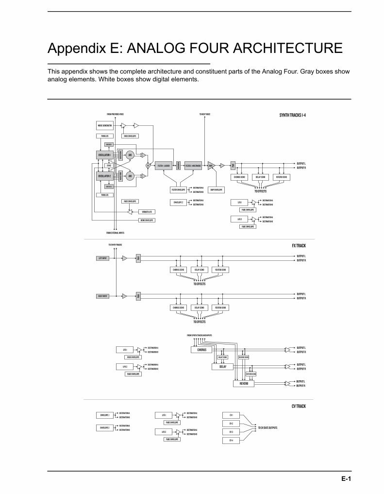
E-1
Appendix E: ANALOG FOUR ARCHITECTUREThis appendix shows the complete architecture and constituent parts of the Analog Four. Gray boxes show analog elements. White boxes show digital elements.
OSCILLATOR 1
FILTER 1 : LADDER FILTER 2 : MULTIMODE
LEFT INPUT
RIGHT INPUT
WAVE
FORM
OVER
DRIVE
PAN
PAN
PAN
AM
AM
WAVE
FORM
OSCILLATOR 2
AMP
SUB OSC 2
SUB OSC 1
NOISE GENERATOR
PWM LFO FADE ENVELOPE
PWM LFO
FADE ENVELOPE
FADE ENVELOPE
FADE ENVELOPE
FILTER ENVELOPE AMP ENVELOPE
CHORUS SEND DELAY SEND REVERB SEND
CHORUS SEND DELAY SEND REVERB SEND
CHORUS SEND DELAY SEND REVERB SEND
LFO 1
LFO 2
ENVELOPE 2
ENVELOPE 1
ENVELOPE 2
VIBRATO LFO
BEND ENVELOPE
SYNC
FADE ENVELOPE
FADE ENVELOPE
LFO 1 CV 1
CV 2
CV 3
CV 4
LFO 2
FADE ENVELOPE DELAY SEND
REVERB SEND
REVERB SEND
FADE ENVELOPE
LFO 1 CHORUS
DELAY
REVERB
LFO 2
FROM EXTERNAL INPUTS
FROM PREVIOUS VOICE
TO SYNTH TRACKS
FROM SYNTH TRACKS AND INPUTS
TO NEXT VOICE
TO EFFECTS
TO EFFECTS
TO EFFECTS
OUTPUT LOUTPUT R
OUTPUT LOUTPUT R
OUTPUT L
TO CV/GATE OUTPUTS
OUTPUT R
OUTPUT LOUTPUT R
OUTPUT LOUTPUT R
OUTPUT LOUTPUT R
DESTINATION A
DESTINATION B
DESTINATION A
DESTINATION B
DESTINATION A
DESTINATION B
DESTINATION A
DESTINATION B
DESTINATION A
DESTINATION B
DESTINATION A
DESTINATION B
DESTINATION A
DESTINATION B
DESTINATION A
DESTINATION B
DESTINATION A
DESTINATION B
DESTINATION A
DESTINATION B
SYNTH TRACKS 1-4
FX TRACK
CV TRACK

E-2 Appendix E: ANALOG FOUR ARCHITECTURE

INDEX 1
INDEX
Symbols+DRIVE 7
AACCENT 39ACCESSORIES
Carrying bag and protective lid 5Rack mount kit 5
ARPEGGIATORS 33Arpeggiator setup 34
CCHAINS 43CLICK TRACK 36CONNECTING THE UNIT 5COPY, PASTE AND CLEAR
Kit 16, 26Pattern 41Track 41Track page 41Trig 41
CREDITS 75Contact information 75Development team 75
CV TRACK 28
DDATA STRUCTURE 7
EEARLY START UP MENU 60EDIT
CV track 28FX track 28Sound 27
ELECTRICAL SPECIFICATIONS 74EMPTY RESET 60
FFILTERS 63
2-Pole 63
4-Pole 63FX TRACK 28
GGLOBAL MENU 46
CV config 53Global slot 46MIDI config 47Project menu 46Synth config 46SysEx dump 56
GRID RECORDING MODE 31
KKITS 16
Clear kit 16Load kit 16Performance mode 16Reload kit 16Save kit 16
LLCD SCREEN 9LEGATO MODE 25LIVE RECORDING MODE 31LOADING
Kits 16Song 45
MMASTER TUNE 46METRONOME 36MIDI
Auto channel 49MIDI channels 49MIDI port config 48MIDI sync 47
MULTI MAP 50Entries 50External trig 51Internal trig 51Pattern play 52
MUTETrack 28

2 INDEX
NNAMING MENU 10
Pop up naming menu 10NOTE MENU 34NOTE SLIDE 39
OOSCILLATORS 61
Sub oscillators 61Waveforms 61, 62
OVERBRIDGE 11
PPARAMETER EDITING 9
Parameter value skip 9Quick parameter editing 9
PARAMETER LOCKS 38PARAMETER SLIDE 40PATTERN MODES 30
Direct jump 30Direct start 30Sequential 30
PATTERN RECORDING MODES 30PATTERNS 29
Copy 41Copy track 41Copy track page 41Copy trig 41Grid recording mode 31Live recording mode 31Parameter locks 38Pattern mode 30Recording modes 30Selecting a pattern 29Tempo 30Trig types 31
PERFORMANCE MODE 16Performance setup 17
POLYPHONY 19Allocation 19Allocation illustrations 21Configuration 19Voices 19
PORTAMENTO 25PROJECTS
Load project 13Manage project 14Save project 13
QQUICK RELOAD 41
Kit 42Pattern 42Song 42Sound 42Track 42
QUICK SAVE 41Kit 42Pattern 42Song 42Track 42
QUICK SCROLLING 10QUICK START 12
RRACK MOUNT KIT 5RECORDING MODES
Grid recording mode 31Live recording mode 31
SSAVING
Kits 16Patterns 32Songs 45Track 32
SCALE SETUPAdvanced 37Normal 36
SETUP EXAMPLES 65AF as filter bank 68AF with electric guitar 72AF with external oscillator 70AF with external synthesizer 65AF with other Elektron gear 67
SONGS 43Transpose 45

INDEX 3
SOUND BROWSER 23SOUND LOCKS 38SOUND MANAGER 24SOUND MENU 23SOUNDS
Clear Sound 25Editing a Sound 27Legato mode 25Playing a Sound 27Portamento 25Rename Sound 25
SWING 40SYSEX DUMP 56
SysEx receive 57SysEx send 56
TTAP TEMPO 30TECHNICAL INFORMATION 74
TEMPO 30Tap tempo 30Tempo Nudge 30
TRANSPOSEDestructive transpose 41Song 45Track 40
TRIG MUTE 38TRIGS
Accent 39Note 31Note slide 39Parameter lock 38Parameter slide 40Sound lock 38Trig mute 38Trigless lock 31
UUSER INTERFACE 9

4 INDEX


![[EN] Analog Lab - User's Manual 20141113downloads.arturia.com/.../manual/Analog_Lab_Manual_1_2_0_EN.pdfARTURIA – Analog Laboratory – USER’S MANUAL 3 Thank you for purchasing](https://static.fdocuments.us/doc/165x107/5aeb6cf57f8b9a585f8d9c20/en-analog-lab-users-manual-analog-laboratory-users-manual-3-thank.jpg)


