ANALIZA VEZANE ENERGIJE I EMISIJE CO PRI...
18
GRAĐEVINSKI MATERIJALI I KONSTRUKCIJE 58 (2015) 2 (3-20) BUILDING MATERIALS AND STRUCTURES 58 (2015) 2 (3-20) 3 ANALIZA VEZANE ENERGIJE I EMISIJE CO 2 PRI IZVOĐENJU MOSTOVSKE KONSTRUKCIJE SA STANOVIŠTA ODRŽIVOSTI ANALYSIS OF THE EMBODIED ENERGY AND THE CO 2 EMISSION IN CONSTRUCTION PROCESS OF A BRIDGE STRUCTURE FROM THE ASPECT OF SUSTAINABILITY Miloš ČOKIĆ Predrag PETRONIJEVIĆ Marija S. TODOROVIĆ Nenad PECIĆ ORIGINALNI NAUČNI RAD ORIGINAL SCIENTIFIC PAPER UDK: 624.21.016 doi:10.5937/grmk1502003C 1 UVOD U radu se razmatra uticaj različitih konstruktivnih rešenja mostovskih konstrukcija na potrebnu primarnu energiju za proizvodnju materijala i elemenata konstrukcije i pri izvođenju konstrukcije. Takođe, analizira se uticaj ovih procesa na životnu sredinu određivanjem odgovarajuće emisije CO 2 . Kao ključni strukturni element u saobraćajnoj mreži, mostovska infrastruktura ne koristi samo brojne prirodne resurse i energiju, već ima i dug životni vek, odnosno upotrebni ciklus, što rezultuje i velikom zabrinutošću povodom uticaja konstrukcije na životnu sredinu. Međutim, aktuelni proces donošenja odluka i dalje se uglavnom bazira na tehničkom, sigurnosnom i ekonomskom aspektu, gde procena uticaja izgradnje i eksploatacije konstrukcije na životnu sredinu još nije integrisana u čitav proces. Iz perspektive zaštite životne sredine, odluke donesene danas mogu imati dugoročan efekat tokom kompletnog životnog veka mosta [1]. U radu su prikazani rezultati proračuna vezane energije i emisije CO 2 za tri rešenja mosta na istoj loka- ciji, različitih konstruktivnih sistema. Na osnovu lokacije Miloš Čokić, master inž. građ. Doc. dr Predrag Petronijević, dipl.inž.građ, Univerzitet u Beogradu, Građevinski fakultet Prof. dr Marija S. Todorović, dipl. maš. inž, urednik Elsevier’s Energy & Buildings Journal-a, Član AINS-a, Fellow-(ASHRAE, REHVA, WAAS), Research Prof. Kyung Hee University, Seoul, Korea, Guest Prof. Southeast University, Nanjing, China Doc. dr Nenad Pecić, dipl.inž.građ, Univerzitet u Beogradu, Građevinski fakultet 1 INTRODUCTION This paper considers the influence of different structural solutions of bridge constructions on the amount of primary energy as part of the production process of construction materials and structural elements, as well as part of construction building process. It also analyzes the impact of these processes on the environment in the form of CO 2 emission. “As the fundamental structures in the transportation network, the bridge infrastructure not only consumes numerous natural resources and energy, but also have long-term life span, which results into significant concerns of the environmental impact. However, the current decision making process is still mainly focused on the technique, safety and economic perspectives, that the environmental assessment is not yet integrated. From the environmental perspective, the decisions made today may have a long-term effect for the whole life cycle of bridge” [1]. The calculation results of the amount of embodied energy and CO 2 emission for three different structural solutions of bridge construction are presented in the Miloš Čokić, MSc Civ. Eng. Docent Predrag Petronijević, PhD Civ. Eng, University of Belgrade, Faculty of Civil Engineering Prof. Marija S. Todorović, PhD, Editor of Elsevier’s Energy & Buildings Journal, Member of AINS-a, Fellow-(ASHRAE, REHVA, WAAS), Research Prof. Kyung Hee University, Seoul, Korea, Guest Prof. Southeast University, Nanjing, China Docent Nenad Pecić, PhD Civ. Eng, University of Belgrade, Faculty of Civil Engineering
Transcript of ANALIZA VEZANE ENERGIJE I EMISIJE CO PRI...
GRAĐEVINSKI MATERIJALI I KONSTRUKCIJE 58 (2015) 2 (3-20) BUILDING MATERIALS AND STRUCTURES 58 (2015) 2 (3-20)
3
ANALIZA VEZANE ENERGIJE I EMISIJE CO2 PRI IZVOĐENJU MOSTOVSKE KONSTRUKCIJE SA STANOVIŠTA ODRŽIVOSTI
ANALYSIS OF THE EMBODIED ENERGY AND THE CO2 EMISSION IN
CONSTRUCTION PROCESS OF A BRIDGE STRUCTURE FROM THE ASPECT OF SUSTAINABILITY
Miloš ČOKIĆ Predrag PETRONIJEVIĆ Marija S. TODOROVIĆ Nenad PECIĆ
ORIGINALNI NAUČNI RAD ORIGINAL SCIENTIFIC PAPER
UDK: 624.21.016doi:10.5937/grmk1502003C
1 UVOD
U radu se razmatra uticaj različitih konstruktivnihrešenja mostovskih konstrukcija na potrebnu primarnuenergiju za proizvodnju materijala i elemenatakonstrukcije i pri izvođenju konstrukcije. Takođe,analizira se uticaj ovih procesa na životnu sredinuodređivanjem odgovarajuće emisije CO2.
Kao ključni strukturni element u saobraćajnoj mreži,mostovska infrastruktura ne koristi samo brojne prirodneresurse i energiju, već ima i dug životni vek, odnosnoupotrebni ciklus, što rezultuje i velikom zabrinutošćupovodom uticaja konstrukcije na životnu sredinu.Međutim, aktuelni proces donošenja odluka i dalje seuglavnom bazira na tehničkom, sigurnosnom iekonomskom aspektu, gde procena uticaja izgradnje ieksploatacije konstrukcije na životnu sredinu još nijeintegrisana u čitav proces. Iz perspektive zaštite životnesredine, odluke donesene danas mogu imati dugoročanefekat tokom kompletnog životnog veka mosta [1].
U radu su prikazani rezultati proračuna vezaneenergije i emisije CO2 za tri rešenja mosta na istoj loka-ciji, različitih konstruktivnih sistema. Na osnovu lokacije
Miloš Čokić, master inž. građ. Doc. dr Predrag Petronijević, dipl.inž.građ, Univerzitet u Beogradu, Građevinski fakultet Prof. dr Marija S. Todorović, dipl. maš. inž, urednik Elsevier’s Energy & Buildings Journal-a, Član AINS-a, Fellow-(ASHRAE, REHVA, WAAS), Research Prof. Kyung Hee University, Seoul, Korea, Guest Prof. Southeast University, Nanjing, China Doc. dr Nenad Pecić, dipl.inž.građ, Univerzitet u Beogradu, Građevinski fakultet
1 INTRODUCTION
This paper considers the influence of different structural solutions of bridge constructions on the amount of primary energy as part of the production process of construction materials and structural elements, as well as part of construction building process. It also analyzes the impact of these processes on the environment in the form of CO2 emission.
“As the fundamental structures in the transportation network, the bridge infrastructure not only consumes numerous natural resources and energy, but also have long-term life span, which results into significant concerns of the environmental impact. However, the current decision making process is still mainly focused on the technique, safety and economic perspectives, that the environmental assessment is not yet integrated. From the environmental perspective, the decisions made today may have a long-term effect for the whole life cycle of bridge” [1].
The calculation results of the amount of embodied energy and CO2 emission for three different structural solutions of bridge construction are presented in the
Miloš Čokić, MSc Civ. Eng. Docent Predrag Petronijević, PhD Civ. Eng, University of Belgrade, Faculty of Civil Engineering Prof. Marija S. Todorović, PhD, Editor of Elsevier’s Energy & Buildings Journal, Member of AINS-a, Fellow-(ASHRAE, REHVA, WAAS), Research Prof. Kyung Hee University, Seoul, Korea, Guest Prof. Southeast University, Nanjing, China Docent Nenad Pecić, PhD Civ. Eng, University of Belgrade, Faculty of Civil Engineering

GRAĐEVINSKI MATERIJALI I KONSTRUKCIJE 58 (2015) 2 (3-20) BUILDING MATERIALS AND STRUCTURES 58 (2015) 2 (3-20)
4
mosta, karakteristika terena i projektnih zahteva,odabrana su tri sledeća konstruktivna rešenja glavnognosećeg sistema:
1) Niz prostih greda; 2) Kontinualna greda; 3) Ramovski sistem.
Kolings (Collings [2006]) izvršio je poređenje formi
mostovskih konstrukcija iz ugla uticaja na životnusredinu, na osnovu kojih su dobijeni neki pokazatelji ovezanoj energiji i emisiji CO2 kod mostova, podpretpostavkom da su ovo racionalni pokazatelji uticajakonstrukcije na životnu sredinu. Glavni rezultati iz ovogpoređenja navode nas na sledeće zaključke:
− Teret uticaja na životnu sredinu tokom izgradnjemosta je približno proporcionalan ceni konstrukcije, štoje uglavnom jednako količini materijala utrošenog zaizgradnju mostovske konstrukcije. Što je veći rasponkonstrukcije, potrebno je utrošiti i više materijala, i na tajnačin se povećava teret uticaja na životnu sredinu.Upotreba materijala s manjom količinom vezane energijei ugljen-dioksida veoma je korisna. U poređenju svećinom mostovskih konstruktivnih tipova, betonskimostovi imaju manju količinu vezane energije i emisijeCO2. Iako betonski mostovi sadrže cement, koji imavisoku količinu vezane energije, to se može ublažitizamenom dela cementa suplementima.
− U toku eksploatacije konstrukcije, postojikonstantan uticaj na životnu sredinu tokom održavanjakonstrukcije. Ovaj efekat povećava se kada se u obzir uzme i preusmeravanje saobraćaja.
− Za mostove srednjih raspona, količina emisije CO2tokom životnog veka konstrukcije od popravki iodržavanja može biti slična onim u fazi izgradnje.
Dobijeni rezultati ukazuju na to da bi održive
mostovske konstrukcije trebalo da imaju za cilj daočuvaju prirodne resurse i minimiziraju količinu otpada,odnosno štetnog uticaja (potreban je efikasan,minimalistički dizajn, koji izbegava ekstravagantnearhitektonske poduhvate), da svedu na minimum„vezanu” energiju u konstrukciji (odgovarajućimodabirom materijala i izvora materijala za funkcionalnepotrebe mosta) i da ostvare dug period eksploatacije, sminimalnim ulaganjima u održavanje konstrukcije (dugživotni vek i upotreba kvalitetnih, izdržljivih materijala)[2].
Radom je obuhvaćena analiza uslovljenostienergetskog utroška i emisije CO2 projektnim rešenjima inačinima izvođenja konstrukcije, za tri prethodnonapregnuta armiranobetonska drumska mosta.
Dobijeni rezultati treba da pokažu mogućnost da se usvajanjem određenog rešenja konstrukcije možedirektno uticati na količinu utrošenog materijala i vezaneenergije konstrukcije, pa samim tim – i na emisiju CO2.
2 OPIS PROJEKTNIH REŠENJA
Profil terena korišćen za projektovanje konstrukcije inačina izvođenja svakog od tri mosta predstavljen je naSlici 1. Potrebno je premostiti rečno korito, saobraćajnicui obostrani pad terena, sa zadatom kotom nivelete navisini od 14,00 m. Projektni maksimalni nivo vode iznosi2,90 m. Takođe, predviđena je i saobraćajnica s profilomširine 10,00 i visine 5,00 m. Lokacija je u okolini
paper. The constructions are located on the same site. Based on the location, terrain characteristics and project requirements, the following three design solutions have been chosen for the main support system:
1) Series of simple beams; 2) Continuous beam; 3) Frame. “Collings (2006) has performed an environmental
comparison of bridge forms that provides some indication of embodied energy and CO2 emissions in bridges, assuming these are a reasonable measure of the environmental burden of the structure. The major findings from that comparison suggest:
− The environmental burden during the construction of a bridge is approximately proportional to its cost, which in turn generally equates to the volume of materials consumed by the bridge. Larger spans use more material and have a higher burden. The use of materials with lower embodied energy and CO2 are beneficial. For most bridge forms the concrete bridge has the lower embodied energy and CO2 emission values. Whilst concrete bridges use cement that has a high embodied energy, this can be mitigated by the use of supplementary cementitious materials as partial cement replacement.
− There is an ongoing environmental burden during the maintenance of paintwork, bearings, joints etc., and a particular spike in that burden when resurfacing is undertaken. This is increased when traffic diversions are accounted for.
− The CO2 emissions during the life of the bridge from repair and maintenance can be similar to those of the construction phase, for bridges of moderate spans.
These findings suggest sustainable bridge
construction should aim to conserve natural resources and minimize waste (be an efficient, minimalist design, avoiding extravagant architectural statements), minimize the embodied energy in the structure (appropriate selection of materials and material sources for the functional demands of the bridge), and have a long life with minimal maintenance input (long service life and durable materials)” [2].
The study includes the analysis of conditionality of embodied energy and CO2 emission with design solutions and construction methods of three prestressed concrete road bridges.
The obtained results show that, with the selection of a specific structural design, the quantity of used construction material, energy and CO2 emission can be directly affected.
2 DESCRIPTION OF THE DESIGN SOLUTIONS
The terrain profile, on which the three bridge constructions should be located, is presented in Figure 1. The project demands bridging the river bed, road and double-sided slope of the terrain, with a given bridge grade at a height of 14.00 m. The projected water level maximum is 2.90 m, and the road profile with a width of

GRAĐEVINSKI MATERIJALI I KONSTRUKCIJE 58 (2015) 2 (3-20) BUILDING MATERIALS AND STRUCTURES 58 (2015) 2 (3-20)
5
Beograda, a predviđeni vek trajanja konstrukcije 100godina.
10.00 m and a height of 5.00 m. The location is in the vicinity of Belgrade, and the projected life cycle of the construction is 100 years.
Slika 1. Profil terena na lokaciji mosta
Figure 1. Terrain profile on the location of the bridge
Parametri zajednički za sva tri rešenja konstrukcije:
− Projekti su urađeni u skladu sa srpskim propisimai podacima dobijenim od Instituta IMS u Beogradu, [3],[4];
− Tip saobraćaja – drumski; II kategorija puta; dvetrake širine po 3,50 m, dve pešačke staze širine 1,5 m;
− Objekti se izvode na tlu nosivosti – σTla = 300 kN/m2;
− Konstrukcije su projektovane od marke betonaMB40, sa upotrebom rebraste armature RA400/500;
− Kablovi za prethodno naprezanje su od užadiØ15.2, zatezne čvrstoće fpk = 1670 N/mm2 i modula elastičnosti E = 195 kN/mm2
− Kolovoz je odvojen od pešačke staze betonskimivičnjacima, dok se na krajevima pešačkih staza nalazizaštitna ograda visine 1,40 m.
− Specifičnosti pojedinačnih rešenja konstrukcije: 1) Niz prostih greda
Glavni nosač je prethodno napregnuta armirano-betonska konstrukcija, koja se sastoji od niza prostihgreda jednakih raspona 21,2 m, s razmakom stubova od22,0 m i ukupnom dužinom od 88,0 m (Slika 2).
Glavne elemente konstrukcije čini pet armirano-betonskih stubova sa svojim temeljima, prethodnonapregnuti montažni glavni nosači, poprečni nosači,kolovozna ploča i montažni delovi pešačkih staza (Slika 3). Glavni nosači i delovi pešačkih staza su montažni,dok se ostali elementi liju na licu mesta.
Parameters common for all three structure solutions:
− The projects were developed in accordance with Serbian regulations and the data obtained from the IMS Institute in Belgrade, [3], [4];
− Traffic type − road traffic; II category; 2 lanes with 3.50 m width, 2 pedestrian paths with 1.5 m width;
− The objects are constructed on a soil with bearing capacity of - σsoil = 300 kN / m2
− The structures are constructed with the MB40 type of concrete, and with ribbed steel reinforcement bars type RA400/500;
− Prestressing cables are composed from Ø15.2 type strands, with tensile strength fpk = 1670 N/mm2 and elasticity modulus E = 195 kN/mm2
− Concrete curbs separate the road- and the pedestrian walkways; a protective fence with a height of 1.40 m is set at the end of the footpaths;
The specifics of the individual structural design solutions:
1) Series of simple beams
The main girder is a prestressed reinforced concrete
structure, which consists of a series of simple beams of equal range of 21.2 m, with distance between the pillars of 22.0 m and an overall length of 88.0 m, Figure 2.
The main elements of the construction consist of five reinforced concrete pillars and their foundations, prestressed precast main girders, cross beams, road deck and prefabricated parts of pedestrian walkways, Figure 3.
Slika 2. Poprečni presek mostovske konstrukcije – glavni nosač je niz prostih greda, (1)
Figure 2. Cross section of the bridge - main deck as a series of simple beams, (1)

GRAĐEVINSKI MATERIJALI I KONSTRUKCIJE 58 (2015) 2 (3-20) BUILDING MATERIALS AND STRUCTURES 58 (2015) 2 (3-20)
6
Glavni nosač mosta u jednom rasponu čine četiriprethodno napregnuta montažna betonska nosačasistema proste grede, „I” poprečnog preseka ikonstantne visine (Slika 3). Nosači su spregnuti kolovoznom pločom i poprečnim nosačima na krajevimai u sredini raspona.
The main girders and walkway parts are prefabri-cated, while the other elements are constructed in site.
The main bridge girder consists of 4 prestressed prefabricated concrete girders in each span that are simple beam system girders, with "I" cross-section and constant height, Figure 3. The girders are joined with road deck and cross girders at the ends and in the middle of the spans.
Slika 3. Poprečni presek konstrukcije (niz prostih greda, [1])
Figure 3. Cross section of the construction (series of simple beams, [1])
2) Kontinualni nosač
Glavni nosač je prethodno napregnuta kontinualnagreda, s rasponima 24,0 + 40,0 + 24,0 metara iukupnom dužinom od, ponovo, 88,0 m (Slika 4).
Glavne elemente konstrukcije čine četiriarmiranobetonska stuba sa svojim temeljima i prethodnonapregnuta greda sandučastog poprečnog presekakonstantne visine, sa dijafragmama nad stubovima i urasponima (Slika 4). Konstrukcija se lije na licu mesta, smontažnim delovima pešačkih staza.
Glavni nosač je prethodno napregnut sa dvanaestkablova koji se pružaju celom dužinom nosača (Slika 10). Visina glavnog nosača je konstantna i iznosi 2,20 m.
2) Continuous beam The main girder is a prestressed continuous beam
with 24.0 + 40.0 + 24.0 m spans and a total length of, again, 88.0 m, Figure 4.
The main construction elements consist of 4 reinforced concrete pillars with their foundations and prestressed beam with box cross-section of constant height, and diaphragms over the pillars and at the middle of the spans, Figure 4. The construction is cast in situ, with mounting parts of walkways.
The main girder is prestressed with 12 cables which stretch throughout the entire girder, Figure 10. The height of the main girder is constant and it values 2.20 m.
Slika 4. Poprečni presek mostovske konstrukcije – glavni nosač je kontinualna greda (2)
Figure 4. Cross section of the bridge - main deck as a continuous beam, (2)
GRAĐEVINSKI MATERIJALI I KONSTRUKCIJE 58 (2015) 2 (3-20) BUILDING MATERIALS AND STRUCTURES 58 (2015) 2 (3-20)
7
3) Ramovski sistem
Glavni nosač je prethodno napregnuta greda krutopovezana sa srednjim stubovima, s rasponima 24,0+40,0+ 24,0 metara i ukupnom dužinom od 88,0 m (Slika 5).
Glavne elemente konstrukcije čine četiriarmiranobetonska stuba sa svojim temeljima i prethodnonapregnuta greda sandučastog poprečnog presekapromenljive visine, sa dijafragmama nad stubovima i urasponima (Slika 5). Konstrukcija se lije na licu mesta, smontažnim delovima pešačkih staza.
3) Frame
The main girder is a prestressed beam, rigidly connected with the middle pillars, with 24.0 + 40.0 + 24.0 m spans and a total length of 88.0 m, Figure 5.
The main construction elements consist of 4 reinforced concrete pillars with their foundations and prestressed beam with box cross-section of varying height, and with diaphragms over the pillars and at the middle of the spans, Figure 5. The construction is cast in situ, with mounting parts of walkways.
Slika 5. Poprečni presek konstrukcije (kontinualna greda, [2])
Figure 5. Cross section of the construction (continuous beam, [2]) Greda je prethodno napregnuta s dve grupe kablova.
Osam kablova pruža se celom dužinom grede, dok suiznad središnjih stubova postavljena još po četiri kraćakabla (Slika 11).
The main girder is prestressed with two groups of cables. Eight cables are stretching throughout the whole length of the girder, and a couple of four shorter cables are placed above the central pillars, Figure 11.
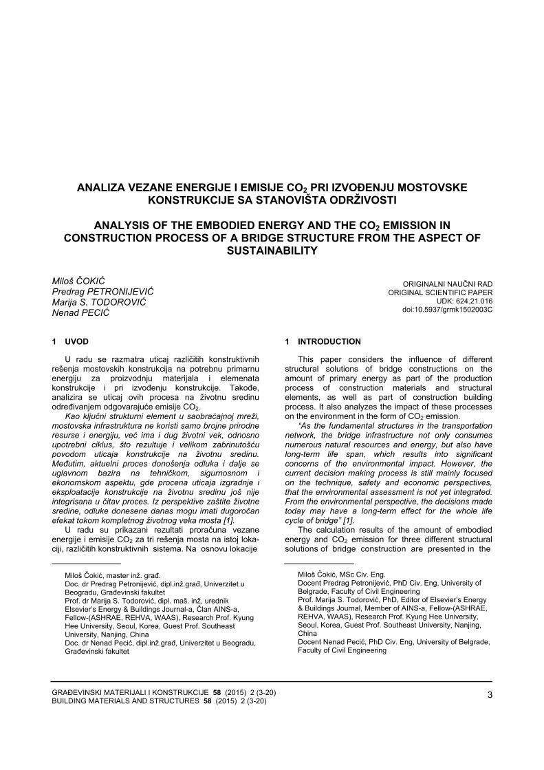
Slika 6. Poprečni presek mostovske konstrukcije - konstrukcia je ramovskog sistema (3)
Figure 6. Cross section of the bridge - main deck as a frame, (3) Visina grede je promenljiva po paraboličnom zakonu
i kreće se od 1,70 m u sredini srednjeg raspona i nadosloncima ivičnih stubova, do 2,70 m nad srednjimstubovima.
The height of the main girder varies according to parabolic law, ranging from 1.70 m in the middle of mid-span and over the edge abutments, up to 2.70 m above the central piers.

GRAĐEVINSKI MATERIJALI I KONSTRUKCIJE 58 (2015) 2 (3-20) BUILDING MATERIALS AND STRUCTURES 58 (2015) 2 (3-20)
8
Slika 7. Poprečni presek konstrukcije (ramovski sistem, [3])
Figure 7. Cross section of the construction (frame, [3])
Slika 8. Šematski prikaz statičkih sistema mostovskih konstrukcija – (1), (2), (3)
Figure 8. A schematic display of the bridge structural systems − (1), (2), (3)
• Način izvođenja radova, izbor potrebnemehanizacije, proračun učinaka mašina i utrošakaenergije
Predviđeno je da iste mašine, s par izuzetaka, budu
korišćene pri izvođenju svake konstrukcije od trinavedene. Glavni nosač prve konstrukcije (1) izvodi semontažom prefabrikovanih prethodno napregnutihnosača na stubove, pomoću auto-dizalica. Glavni nosačidruge (2) i treće (3) konstrukcije izvode se na licu mesta.
Za usvojene načine izvođenja radova, proračunavajuse učinci odabranih mašina na osnovu njihovihmehaničkih i radnih karakteristika, a zatim potrebnoradno vreme i potrošnja energenata. Na osnovu količineutrošene energije, sračunava se emisija CO2.
3 METODOLOGIJA PRORAČUNA, REKAPITULACIJA UTROŠENOG MATERIJALA I ANALIZA REZULTATA
Proračuni i dimenzionisanje konstrukcije izvršeni suna osnovu propisa Republike Srbije (SRPS). Proračun jeurađen po principima teorije I reda (linearna teorijaelastičnosti), uz korišćenje programskog paketa „Tower
• Construction works, selection of the machinery, calculations of the machinery effectiveness and energy consumption
It is predicted that the same machinery (plant), with a
few exceptions, will be used in the construction process of each three structures. The main girders of the first structure (1) – prefabricated prestressed girders, are mounted on the construction pillars with 2 mobile cranes. The main girders of the second (2) and third (3) structure are constructed in situ.
The effectiveness of selected, required operational time and the energy consumed are calculated for the adopted ways of construction works, based on machinery mechanical and performance characteristics. CO2 emission is calculated based on the amount of consumed energy.
3 CALCULUS METHODOLOGY, RECAPITULATION OF THE USED MATERIAL AND THE ANALYSIS OF THE RESULTS
The calculations and the design of constructions were carried out in accordance with the regulations of the Republic of Serbia (SRPS). The calculations were

GRAĐEVINSKI MATERIJALI I KONSTRUKCIJE 58 (2015) 2 (3-20) BUILDING MATERIALS AND STRUCTURES 58 (2015) 2 (3-20)
9
6” za proračun uticaja u elementima konstrukcija.Opterećenja za čije dejstvo je izvršena analiza:
− stalno opterećenje; − saobraćajno opterećenje; − seizmičko opterećenje; − opterećenje vetrom; − temperaturni uticaji.
Nakon proračuna sve tri konstrukcije, urađen je
proračun količina materijala koji se ugrađuju u elementekonstrukcija.
Optimalni izbor građevinskih mašina ima veliki značajza uspeh investicionih projekata u građevinarstvu.Izabrane mašine moraju zadovoljavati sva tehnološkaograničenja na projektu. Cilj izbora građevinskih mašinajeste pronaći kombinaciju koja, uz sve zadate usloveograničenja, ima optimalne ekonomske parametre [5].
Mehanizacija se bira na osnovu predviđenog načinaizvođenja svake od konstrukcija i u skladu s postizanjemoptimalnih rezultata. Radovi na svakoj konstrukciji podeljeni su po pozicijama, u zavisnosti od operacijekoja se izvodi:
− prethodni i pripremni radovi; − zemljani radovi; − betonski radovi; − armirački radovi; − prethodno naprezanje; − završni radovi.
Na osnovu podataka dobijenih iz brošura
proizvođača svake od mašina (tip motora, snagamašine) i prema izračunatom broju radnih sati, pomoćupravilnika Construction Equipment Ownership andOperating Expense Schedule [6], izračunati suenergetski utrošci svake od mašina za svaku odprojektovanih konstrukcija.
• Utrošak betona i armature
1488,81338,9
1514,3
0200400600800
10001200140016001800
niz prostih greda series of simple beamskontinualna greda continuous beamramovski sistem frame
Grafik 1. Utrošak betona u zavisnosti od tipa konstrukcije
Chart 1. Quantity of concrete required, based on structure typ
made according to the principles of the First order theory (linear theory of elasticity) with the use of software package "Tower 6" for the calculation of load influences on the construction. Analyzed load cases are:
− permanent load, − traffic load, − seismic load, − wind load, − temperature influences.
After the needed structural calculations for three
bridges, the amount of the required construction material was calculated.
"The optimal choice of the construction machinery has a great importance for the success of investment projects in the construction industry. Selected machines must comply with all the technological constraints on the project. The objective of construction machinery selec-tion is to find a combination that, with all the given limi-ting conditions, has optimal economic parameters" [5].
The selection of machinery is based on predicted method of construction of the each of structures, in accordance with achieving the optimal results. The works on each structure are divided per positions, depending on the type of operation:
− preliminary and preparatory works, − terrain works, − concrete works, − steel reinforcement work, − pre-stressing, − finishing works.
Based on the data obtained from the manufacturer's
brochure for each machine (engine type, engine power) and calculated number of working hours, the energy consumption of each machine during the work on each construction is calculated, according to the "Construction Equipment Ownership and Operating Expense Schedule" [6].
• Concrete and rebar requirement
116,26114,13
146,22
020406080
100120140160
niz prostih greda series of simple beamskontinualna greda continuous beamramovski sistem frame
Grafik 2. Utrošak armature u zavisnosti od tipa konstrukcije
Chart 2. Quantity of steel rebar required, based on structure type

GRAĐEVINSKI MATERIJALI I KONSTRUKCIJE 58 (2015) 2 (3-20) BUILDING MATERIALS AND STRUCTURES 58 (2015) 2 (3-20)
10
Potrebne količine betona za svaku od tri konstrukcijeslične su i razlikuju se za nekoliko procenata. Utrošakarmature za prvu (1) i drugu (2) konstrukciju je sličan,dok je kod treće (3) dosta veći, što je posledicanaprezanja usled temperaturnih uticaja.
• Utrošak kablova za prethodno naprezanje
Pregled kablova za prethodno naprezanje:
Niz prostih greda: − Tip kablova: 9Ø15.2 − Broj kablova: 4 x 4 x 4 = 64 − Tip kotvi: S11/15 − Broj kotvi: 128
The required amounts of concrete, for each of the three constructions, are very similar and differ by a few percent. Required amount of reinforcement bars for the first (1) and second (2) structure is similar, but a lot higher for the third (3), as a result of stress due to temperature effects.
• Prestressing cables requirement
Overview of used prestressing cables:
Series of simple beams: − Cables type: 9Ø15.2 − Number of cables: 4 x 4 x 4 = 64 − Anchors type: S11/15 − Number of anchors: 128
Slika 9. Trasa rezultantnih kablova, (1)
Figure 9. Prestressing cables resultant route, (1)
Kontinualni nosač: − Tip kablova: 19Ø15.2 − Broj kablova: 12 − Tip kotvi: S19/15 − Broj kotvi: 24
Continuous beam: − Cables type: 19Ø15.2 − Number of cables: 12 − Anchors type: S19/15 − Number of anchors: 24
Slika 10. Trasa rezultantnih kablova, (2)
Figure 10. Prestressing cables resultant route, (2)
Ramovski sistem: − Tip kablova: 17Ø15.2 − Broj kablova: 8 + 2 x 4 = 20 − Tip kotvi: S19/15 − Broj kotvi: 16 + 2 x 8 = 32
Frame: − Cables type: 17Ø15.2 − Number of cables: 8 + 2 x 4 = 20 − Anchors type: S19/15 − Number of anchors: 16 + 2 x 8 = 32
Slika 11. Trasa rezultantnih kablova, (3) Figure 11. Prestressing cables resultant route, (3)
GRAĐEVINSKI MATERIJALI I KONSTRUKCIJE 58 (2015) 2 (3-20) BUILDING MATERIALS AND STRUCTURES 58 (2015) 2 (3-20)
11
12814,7
20101,1
14618,5
0
5000
10000
15000
20000
25000 niz prostih greda series of simple beams
kontinualna greda continuous beam
ramovski sistem frame
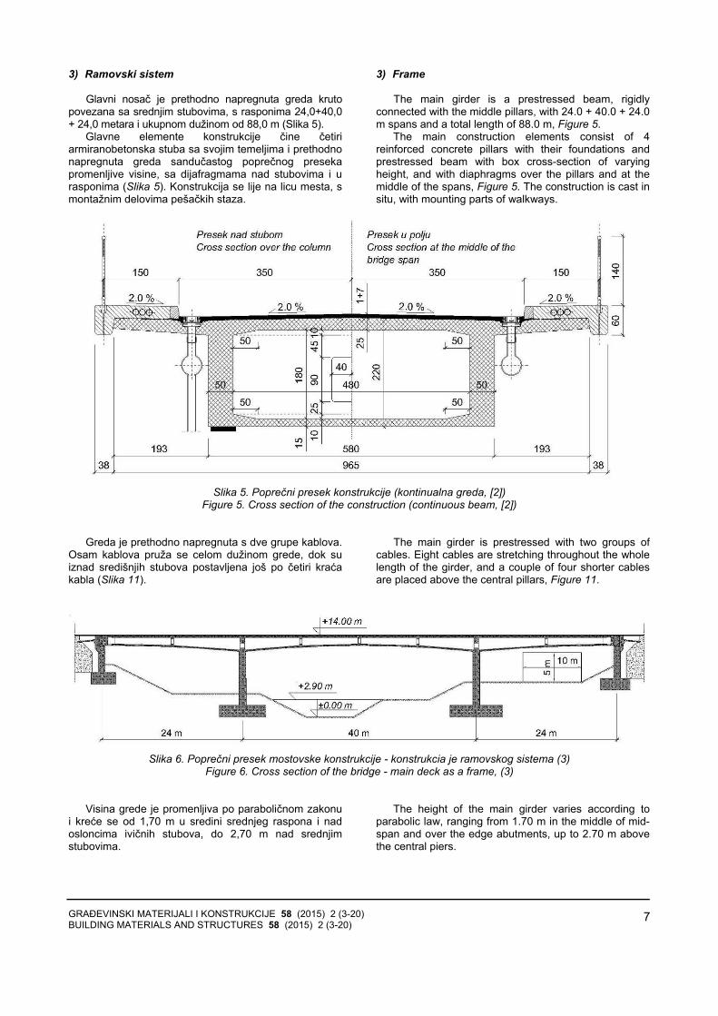
Grafik 3. Ukupna dužina užadi za prethodno naprezanje
Chart 3. Total length of prestressing strands
Najveća ukupna dužina užadi u kablovima glavnog
nosača je u drugoj konstrukciji (2), a zatim slede treća(3) i prva (1) – Grafik 3.
• Utrošak kotvi i ležišta
The maximum total length of the strands of the prestressing cables of the main girder is in the second structure (2), followed by the third (3) and then the first (1), Chart 3. • Requirement of prestressing anchors and bridge
bearings
Tabela 1. Utrošak kotvi i ležišta u zavisnosti od tipa konstrukcije Table 1. Number and type of anchors and bearings depending on the type of construction
U skladu sa usvojenim rešenjima triju konstrukcija,
razlikuju se broj i tip potrebnih kotvi, kao i ležišta zaglavne nosače (Tabela 1).
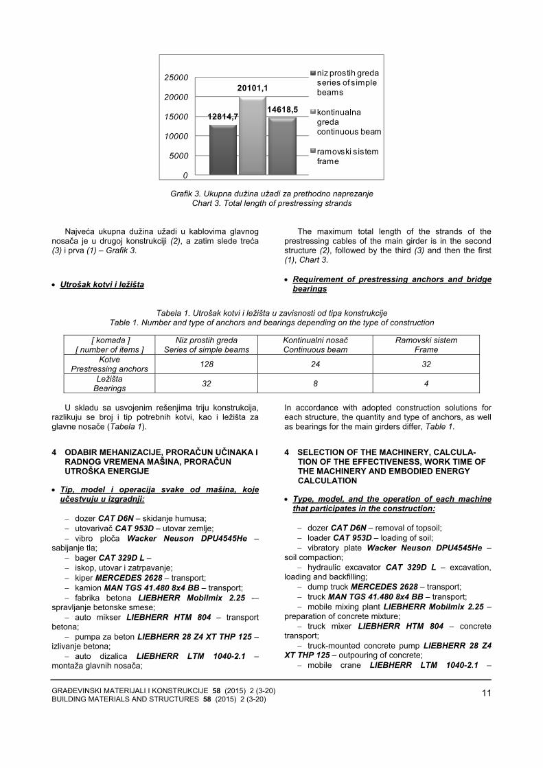
4 ODABIR MEHANIZACIJE, PRORAČUN UČINAKA I RADNOG VREMENA MAŠINA, PRORAČUN UTROŠKA ENERGIJE
• Tip, model i operacija svake od mašina, kojeučestvuju u izgradnji:
− dozer CAT D6N – skidanje humusa; − utovarivač CAT 953D – utovar zemlje; − vibro ploča Wacker Neuson DPU4545He –
sabijanje tla; − bager CAT 329D L – − iskop, utovar i zatrpavanje; − kiper MERCEDES 2628 – transport; − kamion MAN TGS 41.480 8x4 BB – transport; − fabrika betona LIEBHERR Mobilmix 2.25 -–
spravljanje betonske smese; − auto mikser LIEBHERR HTM 804 – transport
betona; − pumpa za beton LIEBHERR 28 Z4 XT THP 125 –
izlivanje betona; − auto dizalica LIEBHERR LTM 1040-2.1 –
montaža glavnih nosača;
In accordance with adopted construction solutions for each structure, the quantity and type of anchors, as well as bearings for the main girders differ, Table 1.
4 SELECTION OF THE MACHINERY, CALCULA-TION OF THE EFFECTIVENESS, WORK TIME OF THE MACHINERY AND EMBODIED ENERGY CALCULATION
• Type, model, and the operation of each machine that participates in the construction:
− dozer CAT D6N – removal of topsoil; − loader CAT 953D – loading of soil; − vibratory plate Wacker Neuson DPU4545He –
soil compaction; − hydraulic excavator CAT 329D L – excavation,
loading and backfilling; − dump truck MERCEDES 2628 – transport; − truck MAN TGS 41.480 8x4 BB – transport; − mobile mixing plant LIEBHERR Mobilmix 2.25 –
preparation of concrete mixture; − truck mixer LIEBHERR HTM 804 – concrete
transport; − truck-mounted concrete pump LIEBHERR 28 Z4
XT THP 125 – outpouring of concrete; − mobile crane LIEBHERR LTM 1040-2.1 –
[ komada ] [ number of items ]
Niz prostih greda Series of simple beams
Kontinualni nosač Continuous beam
Ramovski sistem Frame
Kotve Prestressing anchors 128 24 32
Ležišta Bearings 32 8 4

GRAĐEVINSKI MATERIJALI I KONSTRUKCIJE 58 (2015) 2 (3-20) BUILDING MATERIALS AND STRUCTURES 58 (2015) 2 (3-20)
12
− pervibrator ENAR AX 48 – ugradnja betona; − auto dizalica MAEDA MC174 CRM – držanje
prese za prednaprezanje u zahtevanom položaju; − presa i pumpa za prethodno naprezanje − S - 180/PE - 180 S – utezanje kablova; − presa i pumpa za prethodno naprezanje − S - 310/PE - 300 S – utezanje kablova; − asfaltna baza LINTEC CSD 2500 – spravljanje
asfalta; − finišer CAT AP500E – razastiranje asfalta; − teški valjak BOMAG BW 203 AD-4 – zbijanje
asfalta; − srednje teški valjak BOMAG BW 161 AD-4 –
zatvaranje gornje površine asfalta i − laki valjak BOMAG BW 151 AD-5 – peglanje
gornje površine asfalta. Za sva tri slučaja – (1), (2), (3) – usvojena su ista
rastojanja od gradilišta do objekata za dopremanjepotrebnog materijala, na osnovu čega su računati učincimašina, radno vreme i utrošak energije.
Proračun radnog vremena mašina izveden je izpotrebnih količina materijala za izgradnju svakekonstrukcije, izabranih mašina i njihovih učinaka. Zaproračun utroška energenata korišćeni su američkistandardi – Construction Equipment Ownership andOperating Expense Schedule [6].
• Proračun vezane energije:
Vezana energija predstavlja ukupnu količinuenergije, utrošenu u nekom proizvodnom procesu,odnosno ukupnu količinu energije ugrađene u finalniproizvod.
Ono što se može zaključiti iz proračuna jeste da serazlike u potrošnji energije koju koristi mehanizacija, pre svega, primećuju kod kamiona i kipera, kao i auto-miksera, odnosno transportnih mašina, čija je potrošnjaenergije direktno uslovljena tipom motora, rastojanjemgradilišta od objekata odakle se doprema materijal, kao ikoličinom materijala koji se prevozi. Kako su parametrikoji se odnose na karakteristike motora mašina, kao iudaljenost gradilišta od objekata iz kojih se prevozimaterijal isti za sva tri slučaja, razlika u potrošnji energijedirektno je uslovljena količinom transportovanogmaterijala. Pretpostavljene transportne dužine pojedinihstavki date su u Tabeli 2.
Potrošnja primarne energije po proizvedenoj toniarmature u elektrolučnoj peći prikazana je na Grafiku 4.Ovaj podatak preuzet je iz publikacije CO2 emissions ofthe Swedish steel industry .[7]
Vrednosti energije utrošene pri proizvodnji betona iasfalta preuzete su iz dva izveštaja kanadskog InstitutaAtina (Athena Sustainable Materials Institute). Preuzetisu rezultati energetskog utroška za proizvodnju betonačije karakteristike najviše odgovaraju karakteristikamabetona marke MB 40 po SRPS-u, [8], Grafik 4. Za asfaltje korišćena vrednost utroška primarne energije zamešavinu bez udela recikliranog materijala, [9] – Grafik 4.
mounting of main girders; − concrete vibrator ENAR AX 48 – compaction of
concrete; − mini crane MAEDA MC174 CRM – holding the
prestressing presses in the required position; − the press and prestressing pump S - 180/PE -
180S – prestressing of cables; − the press and prestressing pump S - 310/PE -
300S – prestressing of cables; − asphalt mixing plant LINTEC CSD 2500 – asphalt
mixing; − paver CAT AP500E – spreading of the asphalt; − heavy roller BOMAG BW 203 AD-4 – compaction
of asphalt; − medium roller BOMAG BW 161 AD-4 – closing of
the top surface of asphalt and − light roller BOMAG BW 151 AD-5 – ironing of the
top surface of asphalt.
In all three cases (1), (2), (3), the same distance from the construction site to the materials supplying facilities have been adopted. On that basis – the effectiveness of the machines, their operating time and the energy consumption were calculated. The calculation of the working time of the machinery has been derived from the required quantities of construction materials for each construction, selected machinery characteristics and their effectiveness. For the calculation of consumed energy American standards “Construction Equipment Ownership and Operating Expense Schedule” [6], were used. • Calculation of the embodied energy:
Embodied energy represents a total amount of
energy consumed in a production process, i.e. a total amount of energy embedded in a final product.
According to the calculations it can be concluded that the differences in energy consumption used by the machinery, are primarily noticed at trucks and dump trucks, and mobile-mixer, i.e. transport machinery. Their energy consumption is directly conditioned by the type of their engines, the distance between the construction site and materials supplying facilities, and the quantity of the materials being transported. Since the parameters rela-ted to the machinery engine characteristics, as well as the distance between construction site and the supplyingobjects are the same in all three cases, the difference in energy consumption is directly conditioned by the amount of transported material. Presumed transport lengths of particular processes are provided in Table 2
Consumption of primary energy per tone produced rebar in the electric arc furnace is shown in Chart 4. This data was taken from the publication "CO2 emissions of the Swedish steel industry." [7]
The values of the energy consumed for production of concrete and asphalt are taken from the two reports from the Canadian Athena Institute of (Athena Sustainable Materials Institute). Those values represent the energy, consumed in the production process of concrete whose characteristics correspond the most to the characteristics of concrete, MB 40 according to SRPS, [8] Chart 4. Also, a value of primary energy consumed for the production of asphalt mix without the share of recycled material was used, [9], Chart 4.

GRAĐEVINSKI MATERIJALI I KONSTRUKCIJE 58 (2015) 2 (3-20) BUILDING MATERIALS AND STRUCTURES 58 (2015) 2 (3-20)
13
Tabela 2. Rastojanje između gradilišta i objekata za snabdevanje građevinskim materijalima i elementima konstrukcije Table 2. The distance between construction site and objects for supplying building materials and construction elements
Lokacija objekta Lokation of object
Udaljenost od gradilišta Distance from the site [km]
Manevrisanje na gradilištu On site maneuvering ≈ 0.06
Armaturni pogon Rebar bending 10
Doprema kablova za prethodno naprezanje Prestressing cables shiping 25
Nabavka hidroizolacije Waterproofing delivery 7
Prefabrikacija betonskih ivičnjaka Prefabrication of concrete curbs 20
Nabavka bravarije Metalwork supply 17
Nabavka odvodnih cevi Drain pipes supply 12
Asfaltna baza Asphalt mixing plant 9
Tabela 3. Ukupan utrošak energenata za mehanizaciju Table 3. Total energy consumption of mechanization
Potrošnja energenata Energy consumption
Niz prostih greda Series of simple beams
Kontinualni nosač Continuous beam
Ramovski sistem Frame
Električna energija Electric energy [ kWh ] 1.667,50 1.557,26 1.730,17
Benzin Gasoline [ l ] 28,43 12,44 11,85
Dizel Diesel [ l ] 15.123,20 12.226,51 14.081,01
Ukupno Total [ kWh ] 95.784,60 77.524,13 89.235,41
11,80
0,80
3,46
0
2
4
6
8
10
12
14
armatura steel rebar
beton concrete
asfalt asphalt
Grafik 4. Vezana energija ugrađenih materijala Chart 4. Embodied energy of embedded materials,
[GJ/t], [7], [8], [9]
95785
7752489235
0
20000
40000
60000
80000
100000
120000
niz prostih greda series of simple beamskontinualna greda continuous beam
Grafik 5. Ukupan energetski utrošak mehanizacije Chart 5. Total energy consumption of the machinery
[kWh] Količina energetskog utroška po toni proizvedenog
betona višestruko je manja od količine energije utrošenepo toni proizvedenih armature i asfalta, što će se odrazitina dobijene rezultate.
The amount of energy consumption per tone of concrete is several times smaller than the amount of consumed energy per tone of steel rebar and asphalt,which will be reflected in the obtained results.

GRAĐEVINSKI MATERIJALI I KONSTRUKCIJE 58 (2015) 2 (3-20) BUILDING MATERIALS AND STRUCTURES 58 (2015) 2 (3-20)
14
Zbog masenog udela ugrađenih materijala, najvećakoličina energije će biti utrošena pri proizvodnji betona,što se može i videti na Graficima 6. i 7. Na Grafiku 5.prikazan je energetski utrošak mehanizacije, koji jenajmanji za drugu konstrukciju (2).
Međutim, energetski utrošak mehanizacije je priličnomali u poređenju sa energetskim utroškom za beton,čelik i asfalt. Samim tim, količina vezane energije odmehanizacije dosta je mala u poređenju sa ukupnomvrednošću.
Na Graficima 6. i 7. vidi se uticaj količine betonaugrađenog u konstrukciju, na odnos svakog procesa uukupnoj količini vezane energije.
Sve tri konstrukcije su prethodno napregnuti betonskimostovi, s dominantnim udelom betona u zapreminskomi masenom odnosu ugrađenih materijala. Samim tim,relevantna jedinica, po kojoj će biti izvršena analizarezultata, biće kubni metar betona.
Due to the mass fraction of the incorporated mate-rials, the largest amounts of energy consumption will be in the production of concrete, as can be seen at the Charts 6. and 7. Chart 5. shows the energy consumption of the machinery, which is the smallest for the second structure (2).
However, the energy consumption of the machinery is quite small, compared to the energy consumption for concrete, steel and asphalt production process. There-fore, the amount of embodied energy from the machi-nery will be quite small in comparison with the total value.
Charts 6. and 7. show the impact of quantity of concrete embedded in the structure, to each process ratio in the total amount of embodied energy.
All three structures are prestressed concrete bridges, with a dominant percentage of concrete in the volume and mass ratio of all used materials. Therefore, the relevant unit, per which the analysis of the results will be done, is going to be a cubic meter of concrete.
Tabela 4. Ukupna količina vezane energije Table 4. Total amount of embodied energy
Ukupna količina energije
Total energy amount [ MWh ] Niz prostih greda
Series of simple beams Kontinualni nosač Continuous beam
Ramovski sistem Frame
Mehanizacija Construction machinery 95,78 77,52 89,24
Proizvodnja armature Steel rebar production 381,07 374,10 479,28
Proizvodnja betona Concrete production 827,13 743,82 841,26
Proizvodnja asfalta Asphalt production 92,23 92,23 92,23
Ukupno Total 1.396,21 1.287,67 1.502,00
0
100
200
300
400
500
600
700
800
900
niz prostih greda series of simple beams
kontinualna greda continuous beam
ramovski sistem frame
95,7
8
77,5
2
89,2
4
381,
07
374,
10 479,
28
827,
13
743,
82
841,
26
92,2
3
92,2
3
92,2
3
[ MWh ]
Mehanizacija Construction machinery
Proizvodnja armature Rebar productionProizvodnja betona Concrete productionProizvodnja asfalta Asphalt production
Grafik 6. Ukupna količina vezane energije po procesu
Chart 6. Total amount of embodied energy per production process

GRAĐEVINSKI MATERIJALI I KONSTRUKCIJE 58 (2015) 2 (3-20) BUILDING MATERIALS AND STRUCTURES 58 (2015) 2 (3-20)
15
6.86%6.02%5.94%
27.29%29.05%31.91%
59.24%57.76%56.01%
6.61%7.16%6.14%
Niz prostih greda / Kontinualna greda / Ramovski sistem
Series of simple beams / Continuous beam / Fram
Mehanizacija Construction machinery
Proizvodnja armature Rebar production
Proizvodnja betona Concrete production
Proizvodnja asfalta Asphalt production
Grafik 7. Udeo u količini vezane energije po procesu
Chart 7. Proportional share in total embodied energy amount, per process
Grafik 8. prikazuje odnos ukupne količine vezaneenergije sve tri konstrukcije, kao i vezanu energijuprojektovanu na jedan kubni metar betona. Razlike uukupnoj količini utrošene energije u poređenju snajpovoljnijim slučajem – što je drugo konstruktivnorešenje (2) – iznose približno 10% više u odnosu na prvo(1), odnosno 15% više energije u odnosu na trećerešenje (3).
Razlika u količini vezane energije, po kubnom metrubetona ugrađenog u konstrukciju, u odnosu na drugukonstrukciju (2) iznosi približno 2,5% manje za prvo(1),odnosno približno 3% više za treće rešenje (3).
Pri približnom međusobnom odnosu betona,armature i asfalta u sva tri rešenja i pri upotrebi istog tipamehanizacije, ukupna količina vezane energije najviše bivarirala u zavisnosti od količine betona i armatureugrađenih u konstrukciju.
Najmanja količina vezane energije po m3 betona jeste u prvoj konstrukciji (1), ali to ne rezultuje i najmanjom ukupnom količinom vezane energije u prvojkonstrukciji (1), nego u drugoj (2), što je posledicarazličite količine utrošenog materijala, u zavisnosti odkonstrukcije (Grafik 8).
Chart 8. displays the ratio of total amounts of embodied energy for all three constructions, as well as the total amounts of embodied energy per one cubic meter of concrete. The differences in the total amount of used energy, when compared with the most favourable case, which is the 2nd structural solution (2), are approximately 10% more for the first (1), and 15% more energy used for the third solution (3).
The difference in the amount embodied energy per cubic meter of concrete, embedded into structure, compared to other structure (2) is approximately 2.5% less for first (1), and approximately 3% more for third solution (3).
At an approximate mutual relation of concrete, rebar and asphalt in all three solutions and with the use of the same type of machinery, the total amount of embodied energy vary the most depending on the amount of concrete and steel rebar, embedded in the structure.
The smallest amount of embodied energy per m3 of concrete is in the first structure (1), but it does not result in the lowest total amount of embodied energy in first solution (1), but in second (2), which is the result of different material quantities used for each structure, Chart 8.
1396,21
937,79
1287,67
961,76
1502,00
991,90
0
200
400
600
800
1000
1200
1400
1600
[ MWh ] [ kWh/m3 betona / kWh/m3 of concrete]
niz prostih greda series of simple beams
kontinualni sistem continuous beam
ramovski sistem frame
Grafik 8. Ukupna količina vezane energije Chart 8. Total amount of embodied energy

GRAĐEVINSKI MATERIJALI I KONSTRUKCIJE 58 (2015) 2 (3-20) BUILDING MATERIALS AND STRUCTURES 58 (2015) 2 (3-20)
16
5 EMISIJA CO2 KAO NUSPRODUKT ENERGETSKOG UTROŠKA
Za proračun emisije CO2 od mehanizacije, korišćenesu vrednosti koje prikazuju prosečnu emisiju CO2 na teritoriji Srbije [10], u zavisnosti tipa energenta koji sekoristi za rad mašine:
− električna energija: 0,71779 − benzin: 2,3035 − dizel: 2,6256
Proizvodnja čelika zasniva se na korišćenju
proizvoda na bazi uglja, a posledica toga jeste emisijavelike količine CO2. Emisija CO2 po proizvedenoj toniarmature u elektrolučnoj peći, prikazana je na Grafiku 9[7].
Vrednosti emisije CO2 pri proizvodnji betona i asfaltasu preuzete iz dva izveštaja kanadskog Instituta Atina(Athena Sustainable Materials Institute). Preuzete suvrednosti emisije CO2 pri proizvodnji betona, čijekarakteristike najviše odgovaraju karakteristikamabetona marke MB 40 po SRPS-u, [8], Grafik 9. Za asfaltje korišćena vrednost emisije CO2 za mešavinu bezudela recikliranog materijala, [9] – Grafik 9.
Proračun emisije CO2 od mehanizacije, na osnovu utrošene energije, učinjen je na osnovu podatakaInternacionalne Agencije za Energiju (IEA – InternationalEnergy Agency [11] ).
Na Grafiku 10. data je vrednost emisije ugljen-dioksida pri upotrebi mehanizacije. Vidi se da se zadržaopribližan odnos među konstrukcijskim rešenjima, kao ina Grafiku 5, kao i direktna uslovljenost emisije CO2količinom utrošene energije u slučaju upotrebemehanizacije.
590
12064,5
0
100
200
300
400
500
600
700 kg CO2 / t armature of steel rebarkg CO2 / t betona of concretekg CO2 / t asfalta of asphalt
Grafik 9. Emisija CO2 po toni proizvedenog materijala Chart 9. CO2 emission per tonne of construction
material, [7], [8], [9]
UTabeli 5. i na Graficima 11. i 12, primetno je da je –kao i u slučaju analize vezane energije – dominantnakoličina CO2 emitovana u procesu proizvodnje betona,kao najzastupljenijeg materijala u sve tri konstrukcije.
5 CO2 EMISSION AS A BYPRODUCT OF ENERGY CONSUMPTION
To calculate CO2 emission from the machinery, the values that show the average CO2 emissions on the territory of Republic of Serbia were used [10], depending on the type of energy used to operate the machine:
− electrical energy: 0,71779 − gasoline: 2,3035 − diesel: 2,6256 Production of steel is based on the use of coal
products, which results in the emission of large amounts of CO2. CO2 emissions per tone of steel rebar produced in electric arc furnace are shown in Chart 9 [7].
The data that represent CO2 emissions from the production process of concrete and asphalt are taken from two reports of the Canadian Athena Sustainable Materials Institute. The values of CO2 emissions in concrete production, whose characteristics correspond the most with the characteristics of concrete, MB 40 according to SRPS, are used, [8], Chart 9. CO2 emission data from the asphalt production is taken for a mixture without the share of recycled material, [9], Chart 9.
Calculation of CO2 emission of machinery, based on its energy consumption was made based on the data of the IEA (International Energy Agency) [11].
Chart 10. displays the value of carbon dioxide emission from the use of machinery. The ratio of CO2emission between the structural solutions remained similar, like on the Chart 5. and the direct conditionality between CO2 emission and the amount of energy consumption by the machinery can be seen.
40,97
33,2538,24
0
10
20
30
40
50niz prostih greda series of simple beamskontinualna greda continuous beamramovski sistem frame
Grafik 10. Ukupna emisija CO2 od mehanizacije Chart 10. Total CO2 emission of the machinery [ t ]
It is noticeable (Table 5. and Charts 11. and 12.)
that, as in the case of embodied energy analysis, the dominant amount of CO2 is emitted in the production process of concrete, as predominant material in all three constructions.

GRAĐEVINSKI MATERIJALI I KONSTRUKCIJE 58 (2015) 2 (3-20) BUILDING MATERIALS AND STRUCTURES 58 (2015) 2 (3-20)
17
Tabela 5. Ukupna emisija CO2 Table 5. Total CO2 emission
Ukupna emisija CO2 Total emission of CO2 [ t ]
Niz prostih greda Series of simple beams
Kontinualni nosač Continuous beam
Ramovski sistem Frame
Mehanizacija Construction machinery 40.97 33.25 38.24
Proizvodnja armature Steel rebar production 68.59 67.34 86.27
Proizvodnja betona Concrete production 446.65 401.66 454.28
Proizvodnja asfalta Asphalt production 6.19 6.19 6.19
Ukupno Total 562.40 508.44 584.98
050
100150200250300350400450500
niz prostih greda series of simple beams
kontinualna greda continuous beam
ramovski sistem frame
40,9
7
33,2
5
38,2
468,5
9
67,3
4
86,2
7
446,
65
401,
66
454,
28
6,19
6,19
6,19
[ t ]
Mehanizacija Construction machinery
Proizvodnja armature Rebar productionProizvodnja betona Concrete productionProizvodnja asfalta Asphalt production
Grafik 11. Ukupna emisija CO2 po procesu Chart 11. Total CO2 emission per process
7.28%6.54%6.54%
12.20%13.24%14.75%
79.42%79.00%77.66%
1.10%1.22%1.06%
Niz prostih greda / Kontinualna greda / Ramovski sistem
Series of simple beams / Continuous beam / Fram
Mehanizacija Construction machinery
Proizvodnja armature Rebar production
Proizvodnja betona Concrete production
Proizvodnja asfalta Asphalt production
Grafik 12. Udeo u emisiji CO2 po procesu
Chart 12. Proportional share in total CO2 emission, per process
GRAĐEVINSKI MATERIJALI I KONSTRUKCIJE 58 (2015) 2 (3-20) BUILDING MATERIALS AND STRUCTURES 58 (2015) 2 (3-20)
18
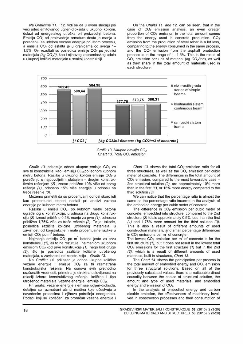
Na Graficima 11. i 12. vidi se da u ovom slučaju jošveći udeo emitovanog ugljen-dioksida u ukupnoj količini, dolazi od energetskog utroška pri proizvodnji betona.Emisija CO2 od proizvodnje armature dosta je manja upoređenju sa udelom vezane energije pri istom procesu,a emisija CO2 od asfalta je u granicama od svega 1–1.5%. Ovi rezultati su posledica emisije CO2 po jedinicimaterijala (kg CO2/t), kao i njihovog zapreminskog udelau ukupnoj količini materijala u svakoj konstrukciji.
On the Charts 11. and 12. can be seen, that in the case of CO2 emission analysis, an even greater proportion of CO2 emission in the total amount comes from the energy used in concrete production. CO2emission from the production of steel rebar is a lot less, comparing to the energy consumed in the same process, and the CO2 emission from the asphalt production process is in the range of 1 -1.5%. This is the result of CO2 emission per unit of material (kg CO2/ton), as well as their share in the total amount of materials used in each structure.
562,40
377,75
508,44
379,75
584,98
386,31
0
100
200
300
400
500
600
700
[ t CO2 ] [ kg CO2/m3 бетона / kg CO2/m3 of concrete ]
niz prostih greda series of simple beams
kontinualni sistem continuous beam
ramovski sistem frame
Grafik 13. Ukupna emisija CO2 Chart 13. Total CO2 emission
Grafik 13. prikazuje odnos ukupne emisije CO2 za sve tri konstrukcije, kao i emisiju CO2 po jednom kubnommetru betona. Razlike u ukupnoj količini emisije CO2 u poređenju s najpovoljnijim slučajem – drugim konstruk-tivnim rešenjem (2) ,iznose približno 10% više od prvogrešenja (1), odnosno 15% više energije u odnosu natreće rešenje (3).
Možemo primetiti da su procentualni odnosi skoro istikao procentualni odnosi nastali pri analizi vezaneenergije po kubnom metru betona.
Razlika u emisiji CO2, po kubnom metru betonaugrađenog u konstrukciju, u odnosu na drugu konstruk-ciju (2) iznosi približno 0,5% manje za prvo (1), odnosnopribližno 1,75% više za treće rešenje (3). To je, takođe,posledica različite količine utrošenog materijala, uzavisnosti od konstrukcije, i male procentualne razlike uemisiji CO2 po m3 betona.
Najmanja emisija CO2 po m3 betona jeste za prvukonstrukciju (1), ali to ne rezultuje i najmanjom ukupnomemisijom CO2 kod prve konstrukcije (1), nego kod druge(2), što je posledica različite količine utrošenogmaterijala, u zavisnosti od konstrukcije – Grafik 13.
Na Grafiku 14. prikazan je odnos ukupne količinevezane energije i emisije CO2 za tri razmatranakonstrukcijska rešenja. Na osnovu svih prethodnosračunatih vrednosti, primetna je direktna uslovljenost narelaciji izbora konstruktivnog rešenja, količine i tipautrošenog materijala, vezane energije i emisije CO2.
Pri analizi vezane energije i emisije ugljen-dioksida, detaljno su razmatrani učinci mašina koje učestvuju unavedenim procesima i njihova potrošnja energenata.Podaci koji su korišćeni za proračun vezane energije i
Chart 13. shows the total CO2 emission ratio for all three structures, as well as the CO2 emission per cubic meter of concrete. The differences in the total amount of CO2 emission, compared to the most favourable case –2nd structural solution (2), are approximately 10% more than in the first (1), or 15% more energy compared to the third solution (3).
We can notice that the percentage ratio is almost the same as the percentage ratio incurred in the analysis of the embodied energy per cubic meter of concrete.
The difference in CO2 emission per cubic meter of concrete, embedded into structure, compared to the 2nd structure (2) totals approximately 0.5% less than the first (1) and 1.75% more amount for the third solution (3). This is also a result of different amounts of used construction materials, and small percentage differences in CO2 emissions per m3 of concrete. The lowest CO2 emission per m3 of concrete is for the first structure (1), but it does not result in the lowest total CO2 emissions for the first structure (1) but in the 2nd (2), which is a result of different amounts of used materials, built in structures, Chart 13.
The Chart 14. shows the participation per process in the total amount of embodied energy and CO2 emission for three structural solutions. Based on all of the previously calculated values, there is a noticeable direct causality between the choice of structural solution, the amount and type of used materials, and embodied energy and emission of CO2.
In the analysis of embodied energy and carbon dioxide emission, the effectiveness of machinery invol-ved in construction processes and their consumption of

GRAĐEVINSKI MATERIJALI I KONSTRUKCIJE 58 (2015) 2 (3-20) BUILDING MATERIALS AND STRUCTURES 58 (2015) 2 (3-20)
19
emisiju CO2 u procesima proizvodnje konstruktivnihmaterijala, korišćeni su iz navedenih izvora [7], [8], [9],[10], [11].
energy were considered in detail. The data used for the calculation of embodied energy and CO2 emissions in the production processes of construction materials, was retrieved from sources [7], [8], [9], [10], [11].
79.42 / 79.00 / 77.66
59.24 / 57.76 / 56.01
12.20 / 13.24 / 14.75
27.29 / 29.05 / 31.91
1.10 / 1.22 / 1.06
6.61 / 7.16 / 6.14
7.28 / 6.54 / 6.54
6.86 / 6.02 / 5.94
0% 20% 40% 60% 80% 100%
Ukupna emisija CO2 Total emission of CO2 [ % ]
Ukupan energetski utrošak Total energy consumption [ % ]
Niz prostih greda / Kontinualna greda / Ramovski sistem
Series of simple beams / Continuous beam / Fram
Proizvodnja betona Concrete production
Proizvodnja armature Rebar production
Proizvodnja asfalta Asphalt production
Mehanizacija Construction machinery
Grafik 14. Procentualni udeo vezane energije i emisije CO2, po procesu
Chart 14. Participation of embodied energy and CO2 emission, per process
6 ZAKLJUČCI
Analizom dobijenih rezultata, prikazana je direktnaveza između konstruktivnog rešenja, načina izvođenja,količine utrošenog materijala i vezane energije, kao iemisije CO2, odnosno uticaja na životnu sredinu.
Svaki korak proračuna uslovljen je prethodno usvojenim rešenjima i ulaznim parametrima. Izborstatičkog sistema konstrukcije direktno se odražava naoblik, dimenzije i broj konstruktivnih elemenata i količinekonstrukcionih materijala. Osim toga, trajanje radova ikoličina utrošene energije uslovljeni su odabirom i karakteristikama mehanizacije i planom izvođenjakonstrukcije. Sve to se odražava na količinu vezaneenergije objekta (mosta), na osnovu prikazanih rezultataproračuna vezane energije i emisije CO2.
U ovom radu prikazan je jedan mogući načinprocene vezane energije i emisije CO2 u procesugradnje betonskih grednih mostova, koji je baziran naproračunu količina u svim glavnim koracima realizacijekonstrukcije i obuhvata sve glavne generatore konačnogrezultata.
Razmatranje međusobne uslovljenosti glavnih koraka u projektovanju i izvođenju mostova daje uvid uto na koji se način ovi procesi odražavaju na energetskiaspekt i emisiju štetnih elemenata na našu okolinu.Prikazani rezultati omogućavaju da se bolje sagledauticaj pojedinih činilaca, ukoliko se kao dodatni kriterijumpri projektovanju uključi i ekološki aspekt.
Dati su kvantitativni rezultati vezane energije i emisijeCO2 za tri konstrukcije mosta različitih statičkih sistema iiste ukupne dužine mosta, svedeni na m3 ugrađenog betona. Prikazano je i procentualno učešće pojedinihkomponenti u ukupnom rezultatu kod svih razmatranihprimera konstrukcija. Dobijene vrednosti vezane energijeiznosile su oko 1000 kWh, a emisija ugljendioksida oko 400 kg CO2, po m3 ugrađenog betona. Direktna veza
6 CONCLUSIONS
The analysis of the obtained results shows direct correlation between the structural design, construction methods, quantity of used materials and embodied energy, as well as CO2 emission and its environmental impact.
Each step of calculation procedure is conditioned by the previously adopted solutions and input parameters. The choice of structural system directly affects the shape, dimensions and number of structural elements and the quantity of construction materials. In addition, the duration of construction works and the amount of embodied energy are conditioned by the selection and the characteristics of machinery and construction plan. Based on the presented results of calculation, the amount of embodied energy of the object (bridge) and CO2emission are consequently affected by selected solutions.
Paper presents a possible method for evaluation of embodied energy and CO2 emission in the process of construction of concrete girder bridges. The method is based on calculation of the amounts in all main steps of the construction and it includes all main generators of the final result.
Correlation of the main steps in the design and construction process of a bridge affects the energy aspect and the emission of harmful elements. Presented results enable better recognition of the impact of certain factors, when the environmental aspect is an additional criterion in the design.
Quantitative results of the embodied energy and CO2emission, for three bridge structures of different struc-tural system and equal total length of the bridge per m3
of concrete are presented. The participation of individual components in the total result, in all considered examplesof the structures is shown. The obtained values were approximately 1000 kWh of embodied energy and - ap-

GRAĐEVINSKI MATERIJALI I KONSTRUKCIJE 58 (2015) 2 (3-20) BUILDING MATERIALS AND STRUCTURES 58 (2015) 2 (3-20)
20
konstruktivnog sistema i vezane energije i emisije CO2izražava se različitim količinama ukupnih materijalapotrebnim za izgradnju mosta na određenoj lokaciji,kada se primenjuju različita konstrukcijska rešenja.
proximately 400 kg of CO2 emission per m3 of built in concrete. Direct correlation of structural system and embodied energy and CO2 emission is expressed through different total quantities of the materials necessary for the construction of bridge at a particular location, when different structural solutions are applied.
7 LITERATURA REFERENCES
[1] Guangli Du, Raid Karoumi, Environmental life cycleassessment comparison between two bridge types:reinforced concrete bridge and steel compositebridge, pg. 1, Third international conference onsustainable construction materials andtechnologies (Kyoto, Japan, August 2013)
[2] Connal, J and Berndt, M. Sustainable Bridges –300 Year Design Life for Second Gateway Bridge. Proceedings, Austroads Bridges Conference,Auckland, 2009, pp. 1-16.
[3] Aleksandar Pakvor, Radomir Folić, Dejstva nakonstrukcije – knjiga 1, izdavač: Građevinskifakultet u Beogradu, Beograd 1995.
[4] Mijat S. Trojanović, Betonski mostovi I, 1970. Beograd
[5] Predrag Petronijević, Nenad Ivanišević, DraganArizanović, Primena računarskog programaCESAD pri izboru građevinskih mašina, zbornikradova ISBN – 978-86-85073-09-0, str. 397–402, Društvo građevinskih konstruktera Srbije, 13.kongres, Zlatibor - „Čigota”, 22–24. septembar2010.
[6] ”Construction Equipment, Ownership andOperating, Expense Schedule - Region III”, U.S.
Army Corps of Engineers, EP 1110-1-8, Volume 3, November 2009
[7] Hans Sandberg, Rune Lagneborg, Birgitta Lindblad, Helén Axelsson and Lars Bentell, CO2emissions of the Swedish steel industry, Scandinavian Journal of Metallurgy 2001; 30: 420–425, Table 2
[8] Cement and structural concrete products: life cycle inventory update #2, Prepared by Athena Sustainable Materials Institute, Ottawa, Canada, 2005; Table 11.3, Table 13.5
[9] A life cycle perspective on concrete and asphalt roadways: Embodied primary energy and global warming potential, Athena Sustainable Materials Institute, Ottawa, Submitted to: Cement Association of Canada, September 2006, Table 3.3
[10] Tools for consumers and designers of solar, http://www.sunearthtools.com/ , pristupljeno podacima: 2014.
[11] International Energy Agency (IEA), http://www.iea.org , pristupljeno podacima: 2014.
REZIME
ANALIZA VEZANE ENERGIJE I EMISIJE CO2 ZA IZVOĐENJE MOSTOVSKE KONSTRUKCIJE SA STANOVIŠTA ODRŽIVOSTI
Miloš ČOKIĆ Predrag PETRONIJEVIĆ Marija S. TODOROVIĆ Nenad PECIĆ
U radu je prikazana uporedna analiza vezane ener-gije i emisije CO2 u procesu gradnje, za tri mostovskekonstrukcije. Analizirane konstrukcije su prethodnonapregnuti betonski mostovi, različitih statičkih sistema,ukupne dužine 88 metara.
Razmatrana je međusobna uslovljenost izbora kon-struktivnih rešenja, načina izvođenja konstrukcije, koli-čine utrošenog materijala, vezane energije i emisije CO2.
Dat je uvid u način na koji se glavni koraci uprojektovanju i izvođenju mostova odražavaju naenergetski utrošak i emisiju CO2, procentualno i uukupnom iznosu.
Dobijeni rezultati bi trebalo da omoguće bolje sagledavanje uticaja pojedinih faktora u procesuizvođenja mostova i njihov uticaj na životnu sredinu.
Ključne reči: Vezana energija, Emisija CO2, Mos-tovske konstrukcije, Održivost, Ekološki aspekt
SUMMАRY
ANALYSIS OF THE EMBODIED ENERGY AND THE CO2 EMISSION IN CONSTRUCTION PROCESS OF A BRIDGE STRUCTURE FROM THE ASPECT OF SUSTAINABILITY
Miloš ČOKIĆ Predrag PETRONIJEVIĆ Marija S. TODOROVIĆ Nenad PECIĆ
This paper presents a comparative analysis of embodied energy and CO2 emission, in the construction process of three bridge structures. Analyzed structures are prestressed concrete bridges with different structural systems and a total length of 88 meters.
The correlation of structural system, construction method, material quantities and embodied energy and CO2 emission were considered.
Influence of the selected solutions in main steps of design and construction on the energy consumption and the emission of CO2 is presented.
The results should provide a better understanding of the effects of certain factors, in the bridge construction process, and their impact on the environment.
Key words: Embodied energy, CO2 emission, Bridge structures, Sustainability, Environmental aspect