
AN4656, PMSM FOC of Industrial Drives using the …€¦ · · 2016-11-231 Introduction This...
14
1 Introduction This application note deals with the field-oriented control (FOC) of a permanent magnet synchronous motor (PMSM) with the DSC 56F84789. The incremental encoder is used for position and speed feedback in this application. This is the typical control algorithm used in industrial drives. The application is controlled by the powerful Freescale Digital Signal Controller (DSC) 56F84789 dedicated to advanced motor control applications. The DSC 56F84789 offers a rich and advanced peripheral set which includes programmable timers, an eFlexPWM module, analogue and communication modules, and so on. This application note describes the control algorithm, software design and hardware set-up using the Tower kit. Freescale Semiconductor Document Number:AN4656 Application Note Rev. 0, 01/2013 PMSM FOC of Industrial Drives using the 56F84789 by: Pavel Rech © 2013 Freescale Semiconductor, Inc. Contents 1 Introduction............................................................1 2 Application Features................................................2 3 DSC 56F844x/5x/7x Key Features.........................2 4 PMSM Control Principle........................................3 5 Application Operation.............................................5 6 System Concept.......................................................5 7 Tower DSC 56F84789 board..................................5 8 Peripherals for PMSM control................................7 9 Faults Protection......................................................9 10 State Machine..........................................................9 11 FreeMASTER and Motor Control Application Tuning Tool......................................10 12 References.............................................................13
Transcript of AN4656, PMSM FOC of Industrial Drives using the …€¦ · · 2016-11-231 Introduction This...
1 IntroductionThis application note deals with the field-oriented control(FOC) of a permanent magnet synchronous motor (PMSM)with the DSC 56F84789. The incremental encoder is used forposition and speed feedback in this application. This is thetypical control algorithm used in industrial drives. Theapplication is controlled by the powerful Freescale DigitalSignal Controller (DSC) 56F84789 dedicated to advancedmotor control applications. The DSC 56F84789 offers a richand advanced peripheral set which includes programmabletimers, an eFlexPWM module, analogue and communicationmodules, and so on. This application note describes the controlalgorithm, software design and hardware set-up using theTower kit.
Freescale Semiconductor Document Number:AN4656
Application Note Rev. 0, 01/2013
PMSM FOC of Industrial Drivesusing the 56F84789by: Pavel Rech
© 2013 Freescale Semiconductor, Inc.
Contents
1 Introduction............................................................1
2 Application Features................................................2
3 DSC 56F844x/5x/7x Key Features.........................2
4 PMSM Control Principle........................................3
5 Application Operation.............................................5
6 System Concept.......................................................5
7 Tower DSC 56F84789 board..................................5
8 Peripherals for PMSM control................................7
9 Faults Protection......................................................9
10 State Machine..........................................................9
11 FreeMASTER and Motor ControlApplication Tuning Tool......................................10
12 References.............................................................13
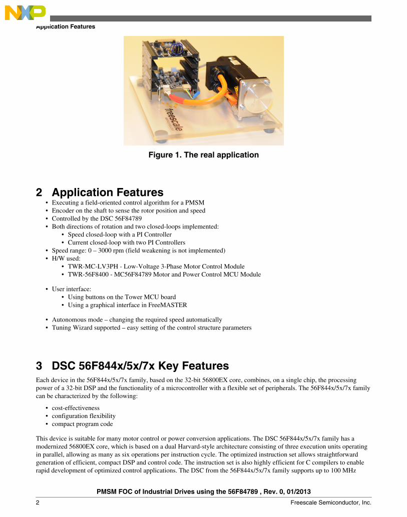
Figure 1. The real application
2 Application Features• Executing a field-oriented control algorithm for a PMSM• Encoder on the shaft to sense the rotor position and speed• Controlled by the DSC 56F84789• Both directions of rotation and two closed-loops implemented:
• Speed closed-loop with a PI Controller• Current closed-loop with two PI Controllers
• Speed range: 0 – 3000 rpm (field weakening is not implemented)• H/W used:
• TWR-MC-LV3PH - Low-Voltage 3-Phase Motor Control Module• TWR-56F8400 - MC56F84789 Motor and Power Control MCU Module
• User interface:• Using buttons on the Tower MCU board• Using a graphical interface in FreeMASTER
• Autonomous mode – changing the required speed automatically• Tuning Wizard supported – easy setting of the control structure parameters
3 DSC 56F844x/5x/7x Key FeaturesEach device in the 56F844x/5x/7x family, based on the 32-bit 56800EX core, combines, on a single chip, the processingpower of a 32-bit DSP and the functionality of a microcontroller with a flexible set of peripherals. The 56F844x/5x/7x familycan be characterized by the following:
• cost-effectiveness• configuration flexibility• compact program code
This device is suitable for many motor control or power conversion applications. The DSC 56F844x/5x/7x family has amodernized 56800EX core, which is based on a dual Harvard-style architecture consisting of three execution units operatingin parallel, allowing as many as six operations per instruction cycle. The optimized instruction set allows straightforwardgeneration of efficient, compact DSP and control code. The instruction set is also highly efficient for C compilers to enablerapid development of optimized control applications. The DSC from the 56F844x/5x/7x family supports up to 100 MHz
Application Features
PMSM FOC of Industrial Drives using the 56F84789 , Rev. 0, 01/2013
2 Freescale Semiconductor, Inc.
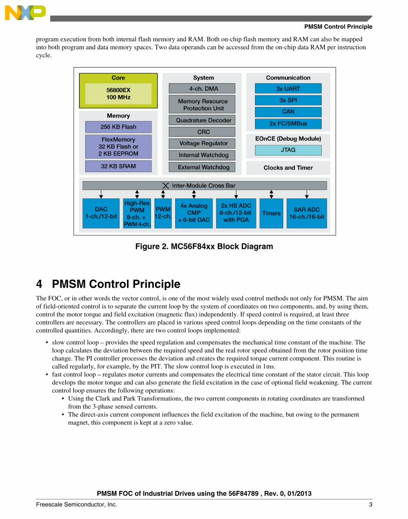
program execution from both internal flash memory and RAM. Both on-chip flash memory and RAM can also be mappedinto both program and data memory spaces. Two data operands can be accessed from the on-chip data RAM per instructioncycle.
Figure 2. MC56F84xx Block Diagram
4 PMSM Control PrincipleThe FOC, or in other words the vector control, is one of the most widely used control methods not only for PMSM. The aimof field-oriented control is to separate the current loop by the system of coordinates on two components, and, by using them,control the motor torque and field excitation (magnetic flux) independently. If speed control is required, at least threecontrollers are necessary. The controllers are placed in various speed control loops depending on the time constants of thecontrolled quantities. Accordingly, there are two control loops implemented:
• slow control loop – provides the speed regulation and compensates the mechanical time constant of the machine. Theloop calculates the deviation between the required speed and the real rotor speed obtained from the rotor position timechange. The PI controller processes the deviation and creates the required torque current component. This routine iscalled regularly, for example, by the PIT. The slow control loop is executed in 1ms.
• fast control loop – regulates motor currents and compensates the electrical time constant of the stator circuit. This loopdevelops the motor torque and can also generate the field excitation in the case of optional field weakening. The currentcontrol loop ensures the following operations:
• Using the Clark and Park Transformations, the two current components in rotating coordinates are transformedfrom the 3-phase sensed currents.
• The direct-axis current component influences the field excitation of the machine, but owing to the permanentmagnet, this component is kept at a zero value.
PMSM Control Principle
PMSM FOC of Industrial Drives using the 56F84789 , Rev. 0, 01/2013
Freescale Semiconductor, Inc. 3
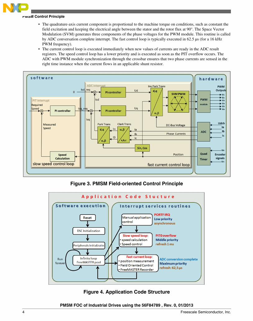
• The quadrature-axis current component is proportional to the machine torque on conditions, such as constant thefield excitation and keeping the electrical angle between the stator and the rotor flux at 90°. The Space VectorModulation (SVM) generates three components of the phase voltages for the PWM module. This routine is calledby ADC conversation complete interrupt. The fast control loop is typically executed in 62.5 µs (for a 16 kHzPWM frequency).
• The current control loop is executed immediately when new values of currents are ready in the ADC resultregisters. The speed control loop has a lower priority and is executed as soon as the PIT overflow occurs. TheADC with PWM module synchronization through the crossbar ensures that two phase currents are sensed in theright time instance when the current flows in an applicable shunt resistor.
Figure 3. PMSM Field-oriented Control Principle
Figure 4. Application Code Structure
PMSM Control Principle
PMSM FOC of Industrial Drives using the 56F84789 , Rev. 0, 01/2013
4 Freescale Semiconductor, Inc.

The incremental encoder is used as the position and speed sensor. It generates the A, B and Index signals processed by theQuad Timer in Quadrature count mode, which counts the actual rotor position. The encoder signals are processed in twoways. On the one hand, the pulses are counted during the constant period – convenient for higher speeds. On the other hand,the measuring time interval between encoder pulses is measured – convenient for low speeds. This speed processing methodincreases the precision of the speed measurement at the expense of the second quad timer module with capture functionalityneeded.
5 Application OperationThe Application can be operated using two buttons, SW1 and SW2, or by using the FreeMASTER graphical controlinterface. The SW2 button first starts the control algorithm and then increases the speed. The SW1 button decreases thespeed, turns off the application, clears a flag or turns the application to the autonomous mode.
6 System ConceptThe application is based on Freescale's modular development platform - the Tower system. Apart from the Tower system,this application includes the 3-Phase permanent magnet synchronous motor. There are two boards only in the Tower system:
• TWR-MC-LV3PH – Low-Voltage 3-Phase Motor Control Module• TWR-56F8400 - MC56F84789 Motor and Power Control MCU Module
These two boards are connected using the primary elevator module, the secondary elevator only keeps the Tower systemtogether. The DSC board with the 56F84789 is placed in the top position of the Tower to enable control of the applicationusing the buttons.
The Figure 2 shows the peripheral set of the MC56F84xx family. For the motor control applications, 6 channels of the PWMmodule are necessary and 2 fast ADC modules with at least 5 channels. Synchronization of the PWM and the ADC module isan important feature. The MC56F84xx family has a CrossBar module which can easily provide synchronization. TheQuadrature decoder is required to decode the Incremental encoder sensor signals. For some applications, can be thecommunication modules can be required. This application based on the Tower system requires the SPI module for MOSFETdriver configuration. Similarly, the SCI communication interface is needed to control the application using theFreeMASTER. The other peripherals are optional.
7 Tower DSC 56F84789 boardThe Figure 5 denotes the Tower DSC board conception. There are three ways to supply power to the Tower DSC board
• through the main power supply connector on the board, from 5 V to 9 V• through the mini-usb connector, with 5 V• through the elevator module with voltage generated by the low-voltage tower board
This application uses the third possibility because the Low-Voltage 3-Phase Motor Control Module has to be supplied by 24V, therefore this voltage is also used for the DSC tower boards.
Application Operation
PMSM FOC of Industrial Drives using the 56F84789 , Rev. 0, 01/2013
Freescale Semiconductor, Inc. 5
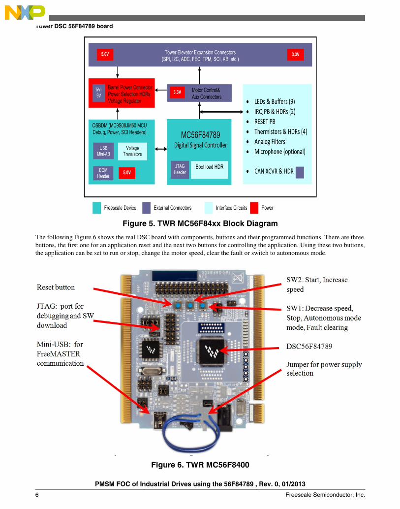
Figure 5. TWR MC56F84xx Block Diagram
The following Figure 6 shows the real DSC board with components, buttons and their programmed functions. There are threebuttons, the first one for an application reset and the next two buttons for controlling the application. Using these two buttons,the application can be set to run or stop, change the motor speed, clear the fault or switch to autonomous mode.
Figure 6. TWR MC56F8400
Tower DSC 56F84789 board
PMSM FOC of Industrial Drives using the 56F84789 , Rev. 0, 01/2013
6 Freescale Semiconductor, Inc.
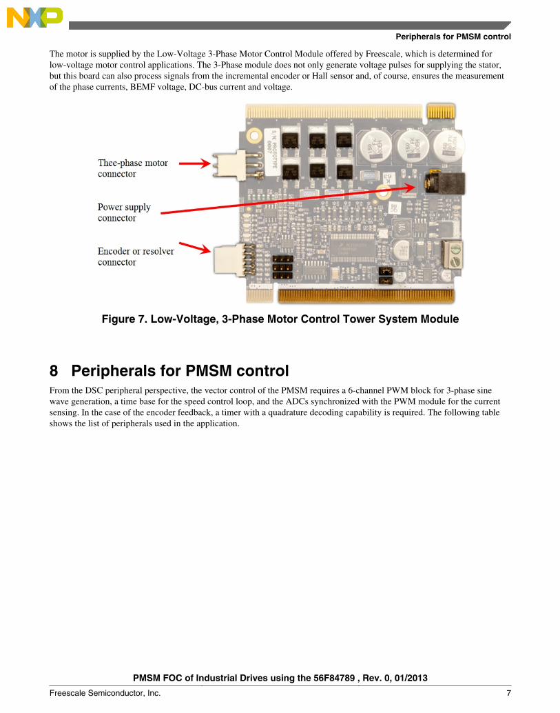
The motor is supplied by the Low-Voltage 3-Phase Motor Control Module offered by Freescale, which is determined forlow-voltage motor control applications. The 3-Phase module does not only generate voltage pulses for supplying the stator,but this board can also process signals from the incremental encoder or Hall sensor and, of course, ensures the measurementof the phase currents, BEMF voltage, DC-bus current and voltage.
Figure 7. Low-Voltage, 3-Phase Motor Control Tower System Module
8 Peripherals for PMSM controlFrom the DSC peripheral perspective, the vector control of the PMSM requires a 6-channel PWM block for 3-phase sinewave generation, a time base for the speed control loop, and the ADCs synchronized with the PWM module for the currentsensing. In the case of the encoder feedback, a timer with a quadrature decoding capability is required. The following tableshows the list of peripherals used in the application.
Peripherals for PMSM control
PMSM FOC of Industrial Drives using the 56F84789 , Rev. 0, 01/2013
Freescale Semiconductor, Inc. 7

Figure 8. The 56F84789 peripherals overview for PMSM FOC
The right peripheral interconnections are also necessary to execute the FOC. Figure 9 denotes the interaction among thecontrol algorithm, peripheral and hardware. It is essential that PWM – ADC synchronization is realized through the crossbarswitch.
Figure 9. Peripheral Interconnection
Peripherals for PMSM control
PMSM FOC of Industrial Drives using the 56F84789 , Rev. 0, 01/2013
8 Freescale Semiconductor, Inc.
9 Faults ProtectionThe control algorithm includes protection against these faults:
• S/W phase overcurrent based on ADC low/high limits automatic comparison.
• S/W DC-bus overvoltage based on ADC high limit automatic comparison.• H/W DC-bus overcurrent based on driver functionality connected with the PWM module.• S/W over/under speed checked by control algorithm speed measurement.
The DC-bus overcurrent is set to a higher value than the S/W phase overcurrent, which is set to a higher value then thecurrent regulator limits. If a HW DC-bus overcurrent fault occurs, the driver will automatically turn off all MOSFETs eventhough the PWM module would generate the pulses. All faults are indicated by LED on the DSC tower board and by LED on3-phase low-voltage module concurrently. The FreeMASTER directly indicates which faults occurred.
10 State MachineThe application software is based on the application state machine built on 4 basic states and expanded using 4 run sub-states:
• Initialization - initialize the variables and MOSFET driver.• Stop - control algorithm runs and the PWM module is disabled.• Run - control algorithm runs and the PWM module is enabled.
• Calibration• Ready• Alignment• Rotation• Automatic mode
• Fault - control algorithm runs, the PWM module is disabled and the fault is indicated.
The application has to be in one of the basic states at anytime. The switching between states is ensured by short transitionfunctions. The transition between the states can be done automatically (for example, from Init to Stop, or Run to Fault states),or called by the user through variables changing (for example, from Run to Stop state, or Rotation to Automatic mode sub-state). The state machine also supports a multi-motor solution. Information about, the actual state or sub-state is stored invariables and the transition between two states is possible only under satisfied logic conditions. The state machine structureallows for easy incorporation of customer specific code and provides a transparent structure of code.
Faults Protection
PMSM FOC of Industrial Drives using the 56F84789 , Rev. 0, 01/2013
Freescale Semiconductor, Inc. 9

Figure 10. Application State Machine
11 FreeMASTER and Motor Control Application Tuning ToolThe FreeMASTER is a real-time debug monitor and data visualization tool. The graphical interface in FreeMASTER is amore comfortable way to control the application. In this way, the user has more possibilities and feedback over controllingthe motor. Moreover, the actual speed values are measured and can be visualized in waveforms.
FreeMASTER and Motor Control Application Tuning Tool
PMSM FOC of Industrial Drives using the 56F84789 , Rev. 0, 01/2013
10 Freescale Semiconductor, Inc.

Figure 11. FreeMASTER Graphic Control Interface
The Recorder functionality of the FreeMASTER is excellent for watching what happens in the DSC during motor controlprocessing. The recorder measurement is based on capturing the variables in periodic interrupts. This application usesmeasurement in the ADC interrupt service routine, meaning each measured sample can be visualized in the recorder. Thefollowing Figure 12 shows the example of a transient state of the application triggered by the recorder. This visualization toolsupports up to 8 variables – placed according to user selection in up to 6 blocks, the arbitrary variables can be used fortriggering.
FreeMASTER and Motor Control Application Tuning Tool
PMSM FOC of Industrial Drives using the 56F84789 , Rev. 0, 01/2013
Freescale Semiconductor, Inc. 11

Figure 12. The Response to a Change in Required Speed Captured by the Recorder
The Tuning Wizard is an upper level motor control tool which enables easy parameter configuration of the control loops,motors or observers. Using this tool implemented in FreeMASTER, you can set up and tune the application constants withoutadvanced motor control knowledge. After the drive has been tuned, you can save all constants to the application header filewhich will be used for project compilation.
FreeMASTER and Motor Control Application Tuning Tool
PMSM FOC of Industrial Drives using the 56F84789 , Rev. 0, 01/2013
12 Freescale Semiconductor, Inc.
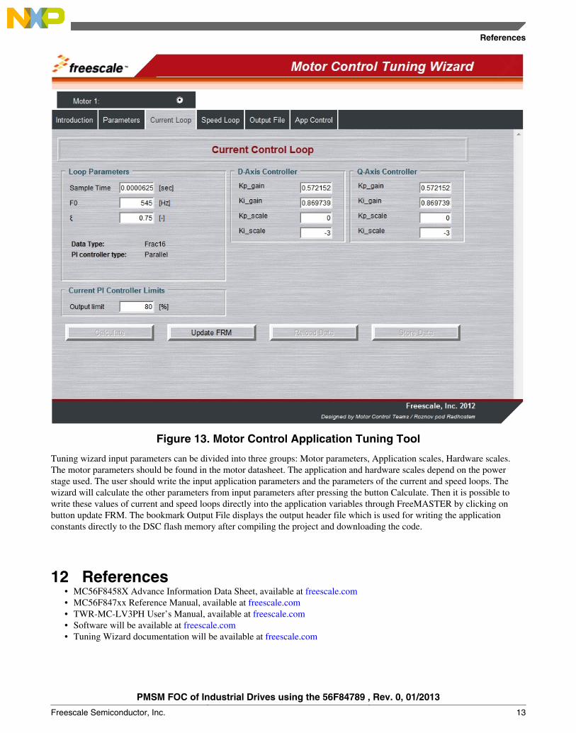
Figure 13. Motor Control Application Tuning Tool
Tuning wizard input parameters can be divided into three groups: Motor parameters, Application scales, Hardware scales.The motor parameters should be found in the motor datasheet. The application and hardware scales depend on the powerstage used. The user should write the input application parameters and the parameters of the current and speed loops. Thewizard will calculate the other parameters from input parameters after pressing the button Calculate. Then it is possible towrite these values of current and speed loops directly into the application variables through FreeMASTER by clicking onbutton update FRM. The bookmark Output File displays the output header file which is used for writing the applicationconstants directly to the DSC flash memory after compiling the project and downloading the code.
12 References• MC56F8458X Advance Information Data Sheet, available at freescale.com• MC56F847xx Reference Manual, available at freescale.com• TWR-MC-LV3PH User’s Manual, available at freescale.com• Software will be available at freescale.com• Tuning Wizard documentation will be available at freescale.com
References
PMSM FOC of Industrial Drives using the 56F84789 , Rev. 0, 01/2013
Freescale Semiconductor, Inc. 13
How to Reach Us:
Home Page:www.freescale.com
Web Support:http://www.freescale.com/support
USA/Europe or Locations Not Listed:Freescale SemiconductorTechnical Information Center, EL5162100 East Elliot RoadTempe, Arizona 85284+1-800-521-6274 or +1-480-768-2130www.freescale.com/support
Europe, Middle East, and Africa:Freescale Halbleiter Deutschland GmbHTechnical Information CenterSchatzbogen 781829 Muenchen, Germany+44 1296 380 456 (English)+46 8 52200080 (English)+49 89 92103 559 (German)+33 1 69 35 48 48 (French)www.freescale.com/support
Japan:Freescale Semiconductor Japan Ltd.HeadquartersARCO Tower 15F1-8-1, Shimo-Meguro, Meguro-ku,Tokyo 153-0064Japan0120 191014 or +81 3 5437 [email protected]
Asia/Pacific:Freescale Semiconductor China Ltd.Exchange Building 23FNo. 118 Jianguo RoadChaoyang DistrictBeijing 100022China+86 10 5879 [email protected]
Document Number: AN4656Rev. 0, 01/2013
Information in this document is provided solely to enable system and softwareimplementers to use Freescale Semiconductors products. There are no express or impliedcopyright licenses granted hereunder to design or fabricate any integrated circuits orintegrated circuits based on the information in this document.
Freescale Semiconductor reserves the right to make changes without further notice to anyproducts herein. Freescale Semiconductor makes no warranty, representation, orguarantee regarding the suitability of its products for any particular purpose, nor doesFreescale Semiconductor assume any liability arising out of the application or use of anyproduct or circuit, and specifically disclaims any liability, including without limitationconsequential or incidental damages. "Typical" parameters that may be provided inFreescale Semiconductor data sheets and/or specifications can and do vary in differentapplications and actual performance may vary over time. All operating parameters,including "Typicals", must be validated for each customer application by customer'stechnical experts. Freescale Semiconductor does not convey any license under its patentrights nor the rights of others. Freescale Semiconductor products are not designed,intended, or authorized for use as components in systems intended for surgical implantinto the body, or other applications intended to support or sustain life, or for any otherapplication in which failure of the Freescale Semiconductor product could create asituation where personal injury or death may occur. Should Buyer purchase or useFreescale Semiconductor products for any such unintended or unauthorized application,Buyer shall indemnify Freescale Semiconductor and its officers, employees, subsidiaries,affiliates, and distributors harmless against all claims, costs, damages, and expenses, andreasonable attorney fees arising out of, directly or indirectly, any claim of personal injuryor death associated with such unintended or unauthorized use, even if such claims allegesthat Freescale Semiconductor was negligent regarding the design or manufacture ofthe part.
RoHS-compliant and/or Pb-free versions of Freescale products have the functionality andelectrical characteristics as their non-RoHS-complaint and/or non-Pb-free counterparts.For further information, see http://www.freescale.com or contact your Freescalesales representative.
For information on Freescale's Environmental Products program, go tohttp://www.freescale.com/epp.
Freescale™ and the Freescale logo are trademarks of Freescale Semiconductor, Inc.All other product or service names are the property of their respective owners.
© 2013 Freescale Semiconductor, Inc.