
AN2958, Using the DC Motor Control eTPU Function Set (set3
24
© Freescale Semiconductor, Inc., 2006. All rights reserved. Freescale Semiconductor Application Note AN2958 Rev. 1, 05/2006 Table of Contents 1 Introduction The enhanced time processing unit (eTPU) is a programmable I/O controller with its own core and memory system, allowing it to perform complex timing and I/O management independently of the CPU. The eTPU module is a peripheral for new 32-bit devices on the industrial and automotive markets (currently, the ColdFire MCF523x and PowerPC MPC5500 families). The eTPU features can be advantageously applied in various motor control applications. The eTPU module is capable of handling motor speed and position sensing, closed loop control of current, speed, and/or position, PWM modulation, etc. The eTPU runs independently of the CPU, making the CPU available for high-level tasks. When the eTPU is utilized for time-critical motor control tasks, it becomes a motor control coprocessor. Freescale Semiconductor provides a library of motor control eTPU functions. The library consists of eTPU functions, which serve as building blocks for various eTPU applications. 1 Introduction.......................................................... 1 2 Function Set Overview ........................................ 2 3 Function Set Usage ............................................. 5 4 Function Set Description ..................................... 8 5 Summary and Conclusions ............................... 23 Using the DC Motor Control eTPU Function Set (set3) Covers the MCF523x, MPC5500, and all eTPU-Equipped Devices by: Milan Brejl System Application Engineer, Roznov Czech System Center
Transcript of AN2958, Using the DC Motor Control eTPU Function Set (set3
Freescale SemiconductorApplication Note
AN2958Rev. 1, 05/2006
Table of Contents1 Introduction..........................................................12 Function Set Overview ........................................23 Function Set Usage.............................................54 Function Set Description .....................................85 Summary and Conclusions ...............................23
Using the DC Motor Control eTPU Function Set (set3)Covers the MCF523x, MPC5500, and all eTPU-Equipped Devicesby: Milan Brejl
System Application Engineer, Roznov Czech System Center
1 IntroductionThe enhanced time processing unit (eTPU) is a programmable I/O controller with its own core and memory system, allowing it to perform complex timing and I/O management independently of the CPU. The eTPU module is a peripheral for new 32-bit devices on the industrial and automotive markets (currently, the ColdFire MCF523x and PowerPC MPC5500 families).
The eTPU features can be advantageously applied in various motor control applications. The eTPU module is capable of handling motor speed and position sensing, closed loop control of current, speed, and/or position, PWM modulation, etc.
The eTPU runs independently of the CPU, making the CPU available for high-level tasks. When the eTPU is utilized for time-critical motor control tasks, it becomes a motor control coprocessor.
Freescale Semiconductor provides a library of motor control eTPU functions. The library consists of eTPU functions, which serve as building blocks for various eTPU applications.
© Freescale Semiconductor, Inc., 2006. All rights reserved.
Function Set Overview
The library is divided in two function sets:• DC motor control eTPU function set• AC motor control eTPU function set
The DC motor control eTPU functions set includes eTPU functions dedicated to DC and brushless DC (BLDC) motor control applications. The AC motor control eTPU function set is dedicated to permanent magnet synchronous motors (PMSM) and AC induction motors (ACIM).
This application note is intended to provide a description of the DC motor control eTPU function set.
2 Function Set OverviewThe DC motor control eTPU function set includes the following motor control techniques:
• Generation of PWM signals• Decoding of signals from Hall sensors• Decoding of signals from a shaft encoder• Commutation of PWM phases• Position control• Speed control• Torque (current) control• DC-bus break control
A motor control drive which utilizes several of the listed techniques can be fully handled by the eTPU.
The DC motor control eTPU function set consists of 12 eTPU functions:• GPIO - general purpose input/output• PWMMDC - PWM master for DC motors
— PWMF - PWM full range— PWMC - PWM commutated
• HD - hall decoder• QD - quadrature decoder
— QD_Home - quadrature decoder home— QD_Index - quadrature decoder index
• ASDC - analog sensing for DC motors• CC - current controller• SC - speed controller• BC - break controller
The eTPU functions are configurable and adjustable using various parameters and options, giving the user the ability to customize these functions to their specific application.
Using the DC Motor Control eTPU Function Set (set3), Rev. 1
Freescale Semiconductor2
Function Set Overview
The following paragraphs briefly describe the purpose of each eTPU function in a motor control application.
2.1 General Purpose Input/Output (GPIO)This function originates from the general eTPU function set (set1), and is included in the DC motor control eTPU function set as well. It can be assigned to an eTPU channel that is not used by any other eTPU functions, in order to use the associated pin for general purposes.
In motor control applications on the MCF523x devices, the GPIO functions can be used to generate an interrupt on a fault. The fault signal, which is usually connected to the eTPU output disable input, can be also connected to the eTPU channel assigned a GPIO function. When the fault signal turns active, selected output channels are immediately disabled by the eTPU hardware. At the same time, the GPIO function generates an interrupt in order to notify the CPU about the fault occurrence.
2.2 DC Motor Control PWM Generator (PWMMDC with PWMF or PWMC)
The PWMMDC, PWMF, and PWMC functions enable the eTPU to generate PWM signals for a voltage controlled inverter. The PWM master (PWMMDC) function synchronizes and updates up to three PWM phases. The phases may be driven either by the PWM full range (PWMF) function that enables a full (0% to 100%) duty-cycle range, or by the PWM commutated (PWMC) function that enables switching the phase ON and OFF.
The DC motor control PWM generator can generate one, two, or three PWM phases. Each phase may be represented by a single PWM channel or a complementary pair of PWM channels with dead-time. The output signal polarity is selectable, and both edge-aligned and center-aligned PWM are supported. Additional options are available for special commutation patterns.
The PWM duty-cycle is controlled by an input parameter whose value corresponds to the generated voltage. Optionally, the phase duty-cycles can be set directly.
For a full description of all features, refer to “Using the DC Motor Control PWM eTPU Functions,” AN2840.
2.3 Hall Decoder (HD)The HD eTPU function is intended to process signals generated by Hall sensors in motion control systems. It uses one, two, three, or four channels to decode Hall sensor signals, and to produce positional and directional information for the CPU. A HD measures periods between detected Hall signal transitions—revolution period and sector period—which can be used by the speed controller for actual motion system speed calculation. A HD also provides the user the ability to commutate motor phases driven by the PWMC function.
For a full description of all features, refer to “Using the DC Motor Control PWM eTPU Functions,” AN2841.
Using the DC Motor Control eTPU Function Set (set3), Rev. 1
Freescale Semiconductor 3
Function Set Overview
2.4 Quadrature Decoder (QD, QD_Index, QD_Home)The QD eTPU functions are intended to process signals generated by a shaft encoder in motion control systems. It uses two channels to decode a pair of out-of-phase encoder signals to produce a 24-bit, bi-directional position counter, together with directional information, for the CPU. A QD counts detected transitions and stores transition times, which can be used by the speed controller function for actual motion system speed calculation.
Additional input channels can be also processed. The index channel receives a pulse on each revolution. Based on the actual direction, a revolution counter is incremented or decremented on the index pulse. Furthermore, additional input channel can indicate a home position. When this position is reached, appropriate actions are taken (a reset of the position counter and the revolution counter).
For a full description of all features, refer to “Using the Quadrature Decoder (QD) eTPU Function,” AN2842.
2.5 Analog Sensing for DC Motors (ASDC)The ASDC function is useful for preprocessing analog values that are measured by an AD converter and transferred to the eTPU data memory by a DMA transfer. The ASDC function can trigger the AD converter, request the DMA transfer, and synchronize with other eTPU functions.
For a full description of all features, refer to “Using the Analog Sensing for DC Motors (ASDC) eTPU Function,” AN2846.
2.6 Current Controller (CC)The purpose of the CC function is to control another eTPU function’s input parameter. The CC function includes a PID controller algorithm. The controller calculates its output based on two inputs: a measured value and a desired value. The measured value is usually provided by the ASDC function, which preprocesses the measured analog values. The desired value can be provided by the CPU or another eTPU function. In the DC motor-control eTPU function set, this function mostly provides the current-closed loop. The CC can be also used as a general PID controller; for example, in positional closed loop.
For a full description of all features, refer to “Using the Current Controller (CC) eTPU Function,” AN2844.
2.7 Speed Controller (SC)The purpose of the SC function is to control another eTPU function’s input parameter. The SC function includes a PID controller algorithm. The controller calculates its output based on two inputs: a measured value and a desired value. The measured value—the actual motor speed—is calculated based on inputs provided by the QD or HD functions. The desired value is an output of a speed ramp, whose input is a SC function parameter, and can be provided by the CPU or another eTPU function. In the DC motor-control eTPU function set, this function mostly provides the speed closed loop
For a full description of all features, refer to “Using the Speed Controller (SC) eTPU Function,” AN2843.
Using the DC Motor Control eTPU Function Set (set3), Rev. 1
Freescale Semiconductor4
Function Set Usage
2.8 Break Controller (BC)The BC function is useful for controlling the DC-bus break. The DC-bus break is required when a motor is driven not only in the motoring mode, but also in the generating mode. The DC-bus break switch can be controlled in an ON/OFF mode or a PWM mode.
For a full description of all features, refer to “Using the Break Controller (BC) eTPU Function,” AN2845.
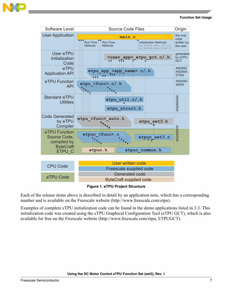
3 Function Set UsageThe DC motor control eTPU function set release consists of the following items.
3.1 eTPU Function Source Code and Binary ImageThe eTPU function source code and the compiled binary image are included in the following package, which is available on the Freescale website (http://www.freescale.com/etpu):
• AN2958SW - DC motor control eTPU function set source code and compiled binary image
It is not necessary for the user to compile the eTPU function source code. Only advanced eTPU users should modify the eTPU functions and then recompile, using the Byte Craft ETPU_C compiler.
The CPU application needs to load the compiled eTPU code into eTPU CODE RAM. The eTPU code binary image is included, together with other initialization items, in the etpu_set3.h file. The eTPU module initialization can be handled by the fs_etpu_init(...) function, which is one of the standard eTPU utilities (etpu_util.c/.h). The eTPU utilities are available on the Freescale web (“General C Functions for the eTPU,” http://www.freescale.com/etpu, AN2864SW).
3.2 eTPU Function APIsThe eTPU function APIs enable the use of eTPU functions in applications. The eTPU function API source code is included in the following packages, which are available on the Freescale website (http://www.freescale.com/etpu):
• AN2840SW - PWMMDC with PWMF or PWMC eTPU functions API• AN2841SW - HD eTPU function API• AN2842SW - QD eTPU functions API• AN2843SW - SC eTPU function API• AN2844SW - CC eTPU function API• AN2845SW - BC eTPU function API• AN2846SW - ASDC eTPU function API
The eTPU function APIs include CPU methods that demonstrate how to initialize, control, and monitor the eTPU function. The CPU application does not need to access eTPU channel registers and/or function parameters directly. Rather, the CPU application can use the eTPU function APIs instead.
Using the DC Motor Control eTPU Function Set (set3), Rev. 1
Freescale Semiconductor 5
Function Set Usage
3.3 eTPU Application APIsThe eTPU application APIs enable the use of eTPU as a motor control coprocessor. The eTPU application API source code, together with example demo applications, are included in the following packages, which are available on the Freescale website (http://www.freescale.com/etpu):
• AN2892SW - “BLDC Motor with Hall Sensors and Speed Closed Loop” eTPU application API, and demo targeted at MCF523x
• AN2954SW - “BLDC Motor with Hall Sensors, Speed Closed Loop and DC-Bus Break Control” eTPU application API, and demo targeted at MCF523x
• AN2955SW - “DC Motor with Speed and Current Closed Loops” eTPU application API, and demo targeted at MCF523x
• AN2957SW - “BLDC Motor with Quadrature Encoder and Speed Closed Loops” eTPU application API, and demo targeted at MCF523x
A set of eTPU functions configured to cooperate together is called eTPU application. An eTPU application API capsulizes several eTPU function APIs. The eTPU application API includes CPU methods which show how to initialize, control, and monitor an eTPU application, and to easily use the eTPU as a motor-control coprocessor.
The eTPU application API is device independent and handles only the eTPU tasks. Where an AD convertor is used together with a DMA transfer to drive a motor, both the AD converter and the DMA must be initialized separately. Their initialization is not covered by the eTPU application API.
Using the DC Motor Control eTPU Function Set (set3), Rev. 1
Freescale Semiconductor6
Function Set Usage
Figure 1. eTPU Project Structure
Each of the release items above is described in detail by an application note, which has a corresponding number and is available on the Freescale website (http://www.freescale.com/etpu).
Examples of complete eTPU initialization code can be found in the demo applications listed in 3.3. This initialization code was created using the eTPU Graphical Configuration Tool (eTPU GCT), which is also available for free on the Freescale website (http://www.freescale.com/etpu, ETPUGCT).
CPU Code
eTPU FunctionSource Code,
compiled byByteCraftETPU_C etpuc.h etpuc_common.h
Code Generatedby eTPUCompiler
etpu_<func>_auto.hetpu_set3.h
etpuc_<func>.cetpuc_set3.c
etpu_util.c/.h
etpu_struct.h
Standard eTPUUtilities
etpu_<func>.c/.heTPU FunctionAPI
etpu_app_<app_name>.c/.heTPUApplication API
<user_app>_etpu_gct.c/.hUser eTPU
InitializationCode
User Application main.cInitialization Methods:my_system_etpu_init();my_system_etpu_start();
Run-TimeMethods
Run-TimeMethods
AN2940-46SW
generatedby eTPUGCT
the onlycodewritten bythe user
AN2892AN2954-57SW
AN
28
64
SW
AN
29
58
SW
Software Level Source Code Files Origin
eTPU Code
User written code
Freescale supplied code
Generated code
ByteCraft supplied code
Using the DC Motor Control eTPU Function Set (set3), Rev. 1
Freescale Semiconductor 7
Function Set Description
4 Function Set Description
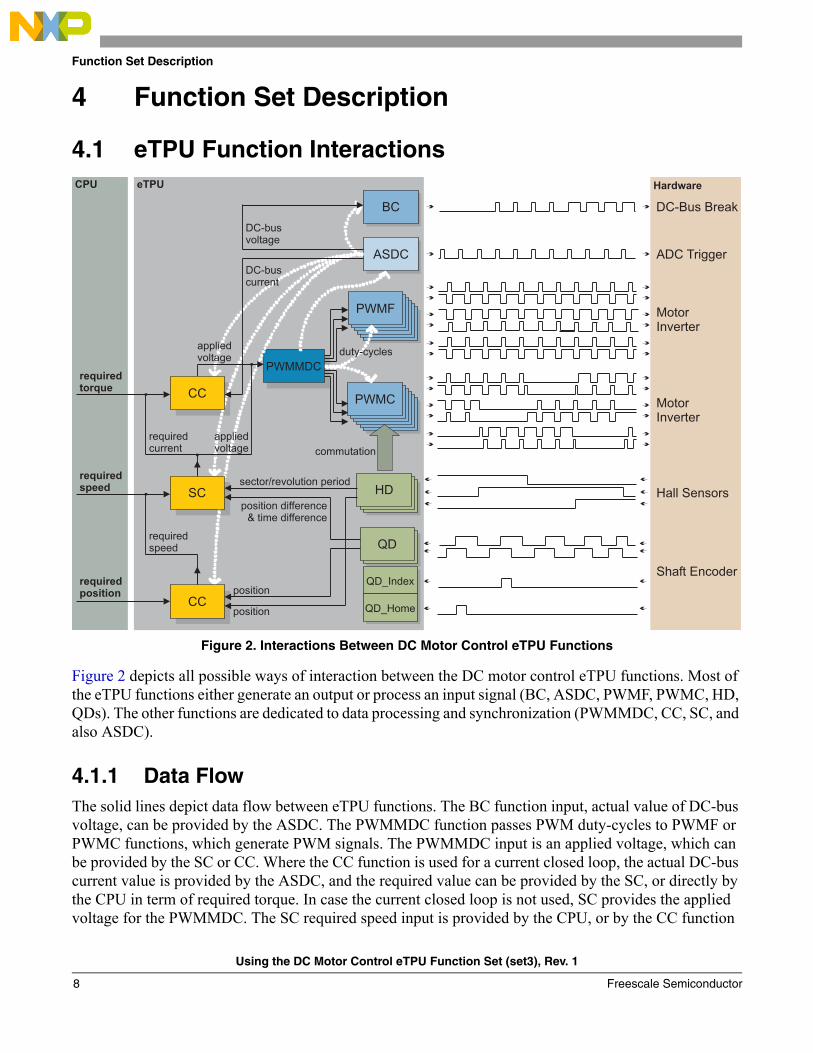
4.1 eTPU Function Interactions
Figure 2. Interactions Between DC Motor Control eTPU Functions
Figure 2 depicts all possible ways of interaction between the DC motor control eTPU functions. Most of the eTPU functions either generate an output or process an input signal (BC, ASDC, PWMF, PWMC, HD, QDs). The other functions are dedicated to data processing and synchronization (PWMMDC, CC, SC, and also ASDC).
4.1.1 Data FlowThe solid lines depict data flow between eTPU functions. The BC function input, actual value of DC-bus voltage, can be provided by the ASDC. The PWMMDC function passes PWM duty-cycles to PWMF or PWMC functions, which generate PWM signals. The PWMMDC input is an applied voltage, which can be provided by the SC or CC. Where the CC function is used for a current closed loop, the actual DC-bus current value is provided by the ASDC, and the required value can be provided by the SC, or directly by the CPU in term of required torque. In case the current closed loop is not used, SC provides the applied voltage for the PWMMDC. The SC required speed input is provided by the CPU, or by the CC function
HD
PWMC
PWMF
QD
QD_Index
QD_Home
ASDC
BC
PWMMDC
SC
CC
requiredtorque
appliedvoltage
requiredspeed
requiredposition
requiredcurrent
appliedvoltage
requiredspeed
sector/revolution period
position difference& time difference
position
position
ADC Trigger
DC-Bus Break
Shaft Encoder
Hall Sensors
MotorInverter
DC-buscurrent
DC-busvoltage
CPU eTPU Hardware
MotorInverter
duty-cycles
CC
commutation
Using the DC Motor Control eTPU Function Set (set3), Rev. 1
Freescale Semiconductor8
Function Set Description
used for positional closed loop control. The SC calculates the actual speed using either a HD parameter sector period or revolution period, or QD parameters position-difference and time-difference. If the CC is used for positional closed loop control, the required position value must be provided by the CPU, while the actual position is read from either the HD or QD. See Figure 2.
4.1.2 SynchronizationThe white dotted lines depict synchronizations. There are several types of synchronization. The PWMMDC function synchronizes and coherently updates up to 6 PWM signals, generated by either the PWMF or PWMC functions. The ASDC function is capable of staying synchronized with the PWM period frames, even if the PWM period changes. Furthermore, the ASDC function is able to synchronize one inner loop and one outer-loop controller. The inner-loop controller is requested for an update every time the ASDC function processes new data. The outer-loop controller is requested for an update once per a defined number of ASDC updates.
The CC, SC, and BC controllers can be run in master mode or slave mode. In master mode, the function executes its updates periodically, independently of the other functions. In slave mode, the updates are executed by an eTPU link sent from another eTPU function, usually the ASDC, as depicted in Figure 2.
The ASDC function can be run in periodic mode or PWM-synchronized mode. In periodic mode, like the CC, SC, and BC in master mode, the ASDC executes its updates periodically, independent of the other functions. In synchronized mode, the ASDC schedules its updates synchronously with PWM periods.
The eTPU links are used for other purposes as well. The CC or SC function may send a link to the PWMMDC in order to notify that a new applied voltage value is ready. The PWMMDC function processes the new voltage value, resulting in new phase duty-cycles and edge times, and sends a link to each subordinate PWMF or PWMC function, to force them to update on the next PWM period edge time.
4.1.3 Commutation ControlThe last type of interaction between the DC motor control eTPU functions is the commutation control. The HD function is able to drive commutations of the PWM phases generated by the PWMC.
4.2 eTPU Requests Generated to the CPU
4.2.1 Interrupt RequestMost of the DC motor control eTPU functions generate an interrupt request to the CPU. No application would handle all of these interrupts. Those interrupts which are useful to the CPU application can be enabled using the eTPU channel interrupt enable register (CIER). The other interrupts should stay masked.
The PWMMDC function requests a CPU interrupt periodically each PWM period. In the demo application, this interrupt is used to activate the FreeMASTER recorder. Thanks to this, time behaviors of any eTPU internal variable can be tracked and drawn in the FreeMASTER recorder window on a PC, with a time step equal to one PWM period length.
Using the DC Motor Control eTPU Function Set (set3), Rev. 1
Freescale Semiconductor 9
Function Set Description
The CC, SC, and BC functions can be configured to request the CPU interrupt periodically, once per a defined number of updates.
The ASDC function requests a CPU interrupt periodically prior to each update. This interrupt can be used by the CPU to pass data from an AD converter to eTPU DATA RAM, in case a DMA transfer is not utilized.
The HD function requests a CPU interrupt once per detected Hall signal transition.
The QD function requests a CPU interrupt if the QD position counter reaches one of two defined values.
The GPIO function, if configured for an input, requests a CPU interrupt when a defined transition is detected.
4.2.2 DMA RequestSome of the DC motor control eTPU functions also generate a DMA request. The DMA requests which are useful to the application must be enabled using the eTPU channel data transfer request enable register (CDTRER).
The ASDC function requests a DMA transfer periodically prior to each update. Depending on the configuration, the DMA transfer can trigger an AD converter or transfer the converted sample data to the eTPU DATA RAM.
The GPIO function, if configured for an input, requests a DMA transfer when a defined transition is detected.
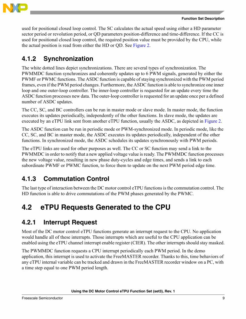
4.2.3 Global ExceptionAll of the DC motor control eTPU functions generate a global exception if the function runs into an unhandled state. The global exception is a global eTPU interrupt, which can be asserted in the following ways:
• eTPU code RAM multiple input signature calculator (MISC) error• Detection of an illegal eTPU instruction• Generation by the eTPU microcode itself
The source of the global exception can be checked in the eTPU module configuration register (MCR). If the global exception was asserted by the microcode, the interrupt handler routine may decode a 32-bit word located at the eTPU data RAM base address. The word includes additional information useful in locating the source of the error.
Using the DC Motor Control eTPU Function Set (set3), Rev. 1
Freescale Semiconductor10
Function Set Description
Figure 3. Global Error Decoding
4.3 eTPU Timing and Engine LoadThe eTPU function, in general, is an event driven state machine. The eTPU function handles events coming from the channel hardware (input transitions and output matches), from another channel (links), or from the CPU (host service requests). The eTPU function uses the eTPU engine to execute the event handler. As there are several eTPU functions running simultaneously on eTPU channels, and only one eTPU engine for 32 channels, it may happen that many eTPU channels request a service at the same time. Based on the channel priorities and eTPU scheduler algorithm, only one channel is granted a service, while the other channels have to wait. The waiting time extends the service latency. If the latency is too long, a malfunction may occur. The worst case latency of one eTPU channel is dependent upon the activity on the other eTPU channels. For a particular eTPU configuration, it has to be ensured that no channel’s worst-case latency is longer then an allowable maximum.
The calculation of the worst-case latencies is not a trivial task. A slightly specialized approach can be used for the motor control eTPU applications. The motor control functions, if used in a standard manner, follow a timing scheme which is easy to understand. Based on it, an average and a peak eTPU time load can be calculated. If the peak time load is lower than 100%, a proper function of the particular eTPU configuration is ensured.
4.3.1 Calculation of eTPU Time Load in Motor Control Applications
For calculation of the eTPU time load, performance values of all the eTPU functions in use are needed. The performance values are included with the function set release, in the readme.txt file, and also in the eTPU function application notes. eTPU function performance is usually expressed in terms of maximum eTPU-busy time per a specified unit, in eTPU cycles. The unit can be expressed as a particular time period, also in eTPU cycles, with knowledge of the application. Then, a quotient of these values expresses the contribution of the eTPU function to the overall eTPU time load. A sum of all active eTPU function contributions gives the average eTPU time load.
The peak eTPU time load is usually achieved when all eTPU function activities happen to cumulate in one PWM period. The maximum eTPU-busy times of all active eTPU functions must be summed at first, and then divided by the PWM period, expressed in eTPU cycles. The result is the peak eTPU time load.
Transition B Latched
Transition A Latched
Match B Latched
Match A Latched
Not Used
11 1013 12 0
Not Used
31Bit: 16 15
Channel Number
79 8
Link Service Request Latched
Using the DC Motor Control eTPU Function Set (set3), Rev. 1
Freescale Semiconductor 11
Function Set Description
The following examples show a calculation of average and peak eTPU time loads for a couple of particular applications.
4.3.1.1 Example 1: BLDC Motor with Hall Sensors and Speed Closed LoopThe application runs on a 150 MHz ColdFire MCF5235. On MCF523x devices, the eTPU module clock is equal to the peripheral clock, which is a half of the CPU clock, hence 75 MHz. Note, that the eTPU module clock is equal to the CPU clock on PowerPC MPC5500 devices.
This application utilizes the following eTPU functions:• PWMMDC with PWMC• HD• SC
The readme.txt file of the DC motor control eTPU function set, release 1.01, states the following performance values:
Funct. | Mode of operation | max eTPU busy time per | eTPU cycles-------+--------------------------------+------------------------+------------PWMMDC | modulation: voltage sign/unsign| one period | 946with | update: normal | period-update time | 216PWMC | number of phases: 3 | Minimum update time | 816phases | phases type: compl. pairs | Longest thread | 398-------+--------------------------------+------------------------+------------HD | commutation processing enabled | one sector | 308-------+--------------------------------+------------------------+------------SC | Master mode, HD, PI controller | one update | 244-------+--------------------------------+------------------------+------------
The contribution of the PWMMDC with PWMC functions to the overall eTPU time load (CPWMMDC+PWMC) is dependent on the PWM period. The PWM period, in eTPU cycles, is equal to a quotient of the eTPU frequency (75 MHz) and PWM frequency (20 kHz).
The contribution of the HD function to the overall eTPU time load (CHD) is dependent on the sector period. The sector period is one sixth of the electrical revolution period. The number of motor electrical revolutions per one mechanical revolution is given by the number of motor pole pairs (4). The shortest mechanical revolution period is calculated using the maximum motor speed (10000rpm).
The contribution of the SC function to the overall eTPU time load (CSC) is dependent on the update period. The SC update is executed every second PWM period. The SC update frequency is 10 kHz.
The average eTPU time load results in 30%, which is the sum of all active eTPU function contributions:
CPWMMDC PWMC+946
75MHz 20kHz⁄--------------------------------------- 0.252= =
CHD308
75MHz 60⋅( ) 10000rpm 6 4⋅ ⋅( )⁄----------------------------------------------------------------------------------- 0.016= =
CSC244
75MHz 10kHz⁄--------------------------------------- 0.033= =
eTPULoadaverage C= PWMMDC PWMC+ C+ HD CSC+ 0.252 0.016 0.033+ + 0.301= =
Using the DC Motor Control eTPU Function Set (set3), Rev. 1
Freescale Semiconductor12
Function Set Description
The peak eTPU load comes up in the situation where the SC update and also one HD transition are processed within the same PWM period, together with the PWM generation:
The peak eTPU time load results in 40%. There is up to 60% of eTPU performance left for additional tasks.
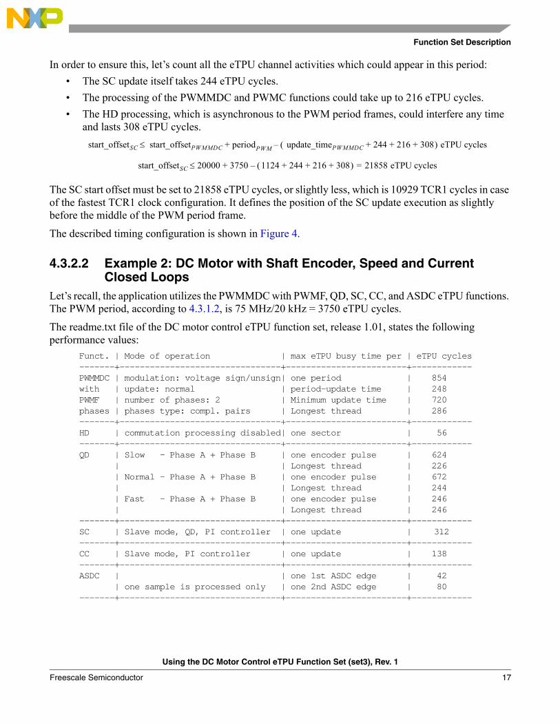
4.3.1.2 Example 2: DC Motor with Shaft Encoder, Speed and Current Closed Loops
The application runs again on a 150 MHz ColdFire MCF5235 with a 75 MHz eTPU module clock.
This application utilizes the following eTPU functions:• PWMMDC with PWMF• QD• SC• CC• ASDC
The readme.txt file of the DC motor control eTPU function set, release 1.01, states the following performance values:
Funct. | Mode of operation | max eTPU busy time per | eTPU cycles-------+--------------------------------+------------------------+------------PWMMDC | modulation: voltage sign/unsign| one period | 854with | update: normal | period-update time | 248PWMF | number of phases: 2 | Minimum update time | 720phases | phases type: compl. pairs | Longest thread | 286-------+--------------------------------+------------------------+------------HD | commutation processing disabled| one sector | 56-------+--------------------------------+------------------------+------------QD | Slow - Phase A + Phase B | one encoder pulse | 624 | | Longest thread | 226 | Normal - Phase A + Phase B | one encoder pulse | 672 | | Longest thread | 244 | Fast - Phase A + Phase B | one encoder pulse | 246 | | Longest thread | 246-------+--------------------------------+------------------------+------------SC | Slave mode, HD, PI controller | one update | 232-------+--------------------------------+------------------------+------------CC | Slave mode, PI controller | one update | 138-------+--------------------------------+------------------------+------------ASDC | | one 1st ASDC edge | 42 | one sample is processed only | one 2nd ASDC edge | 80-------+--------------------------------+------------------------+------------
eTPULoadpeak946 308 244+ +75MHz 20kHz⁄--------------------------------------- 0.399= =
Using the DC Motor Control eTPU Function Set (set3), Rev. 1
Freescale Semiconductor 13
Function Set Description
The contribution of the PWMMDC with PWMF functions to the overall eTPU time load (CPWMMDC+PWMF) is dependent on the PWM period. The PWM period, in eTPU cycles, is equal to a quotient of eTPU frequency (75 MHz) and PWM frequency (20 kHz).
The contribution of the QD function to the overall eTPU time load (CQD) is dependent on the number of shaft encoder pulses (1024) and the motor speed (maximum 1800rpm).
The contribution of the SC function to the overall eTPU time load (CSC) is dependent on the update period. The SC update is executed every 10th PWM period. The SC update frequency is 2 kHz.
The contribution of the CC function to the overall eTPU time load (CCC) is dependent on the update period. The CC update is executed every PWM period. The CC update frequency is 20 kHz.
The contribution of the ASDC function to the overall eTPU time load (CASDC) is dependent on the update period. During an update, both the first and then the second edges are processed. The ASDC update is executed every PWM period. The ASDC update frequency is 20 kHz.
The average eTPU time load results in 58%, which is the sum of all active eTPU function contributions:
The peak eTPU time load comes up during the PWM period in which the SC update is processed. The other eTPU functions consume a constant eTPU time each PWM period, while the SC function, whose update is executed every 10th period, consumes in this period 10-times more than on average:
The peak eTPU time load results in 64%.
In order to ensure an efficient usage of eTPU engine time, and the correct functionality of the QD (which means ensuring that all encoder transitions are handled), additional calculations need to be done. This will be described in the following chapter.
4.3.2 eTPU Timing ConfigurationUp to now, eTPU average time load and peak time load relating to one PWM period have been discussed. Now, the timing within one PWM period, and its configuration, will be explained.
Most of the DC motor control eTPU functions (SC, CC, BC, and ASDC, in master mode, as well as PWMMDC) have a parameter start offset and a parameter period. These parameters are used to
CPWMMDC PWMF+854
75MHz 20kHz⁄--------------------------------------- 0.228= =
CQD672
75MHz 60⋅( ) 1800rpm 1024⋅( )⁄---------------------------------------------------------------------------------- 0.275= =
CSC232
75MHz 2kHz⁄------------------------------------ 0.006= =
CCC138
75MHz 20kHz⁄--------------------------------------- 0.037= =
CASDC42 80+
75MHz 20kHz⁄--------------------------------------- 0.033= =
eTPULoadaverage C= PWMMDC PWMF+ C+ QD CSC CCC C+ + ASDC+ 0.228 0.275 0.006 0.037 0.033+ + + + 0.579= =
eTPULoadpeak C= PWMMDC PWMF+ C+ QD 10 C⋅ SC CCC C+ + ASDC+ 0.635=
Using the DC Motor Control eTPU Function Set (set3), Rev. 1
Freescale Semiconductor14
Function Set Description
synchronize the functions. The PWMMDC period parameter defines the PWM period. The SC, CC, BC, and ASDC periods should be set to an integer multiple of the PWM period, in order to keep all the functions synchronized. The start offset defines the time from the start of the eTPU time bases to the first function action, which is an update on CC, SC, and BC, first edge on ASDC, and PWM period edge on PWMMDC. The differences between the start offsets of each function determine the relative time shifts between the eTPU function actions.
If the SC, CC, or BC functions run in slave mode, its update is executed on a link from another channel (usually the ASDC), which determines the timing. If the ASDC function runs in PWM-synchronized mode, its timing is determined by the edge offset parameter, which defines the offset between the PWM period edge time and the ASDC first edge.
There is a PWMMDC parameter, called update time, which is very important for motor control eTPU application timing. The update time is the time period needed to coherently update all PWM phases by new duty-cycle values. If the update time is correctly set, and a new PWMMDC input voltage is written before the update time prior to the PWM period end, the PWM phases are coherently updated, applying the new duty cycles from the next PWM period. If the new input voltage is written later, the PWM phases are not updated from the next PWM period but from the following one. The minimum update time for each configuration of PWMMDC with PWMF or PWMC is written in the table of performance values, included with the function set release in the readme.txt file. This value can be applied in the case when no other eTPU function could interfere in the sequence of update threads. The eTPU functions running synchronously with the PWM periods (SC, CC, BC, ASDC) can be configured to execute in other parts of the PWM period, and hence not interfere in the PWM update process. The eTPU functions running asynchronously with the PWM periods (HD, QD) can interfere, and the eTPU update time needs to be prolonged.
The following examples show the configuration of eTPU timing for a couple of particular applications.
4.3.2.1 Example 1: BLDC Motor with Hall Sensors and Speed Closed LoopLet’s recall, the application utilizes the PWMMDC with PWMC, HD, and SC eTPU functions. The PWM period, according to 4.3.1.1, is 75 MHz/20 kHz = 3750 eTPU cycles.
The readme.txt file of the DC motor control eTPU function set, release 1.01, states the following performance values:
Funct. | Mode of operation | max eTPU busy time per | eTPU cycles-------+--------------------------------+------------------------+------------PWMMDC | modulation: voltage sign/unsign| one period | 946with | update: normal | period-update time | 216PWMC | number of phases: 3 | Minimum update time | 816phases | phases type: compl. pairs | Longest thread | 398-------+--------------------------------+------------------------+------------HD | commutation processing enabled | one sector | 308-------+--------------------------------+------------------------+------------SC | Master mode, HD, PI controller | one update | 244-------+--------------------------------+------------------------+------------
Using the DC Motor Control eTPU Function Set (set3), Rev. 1
Freescale Semiconductor 15
Function Set Description
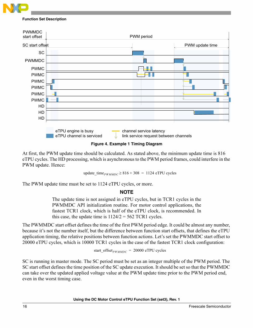
Figure 4. Example 1 Timing Diagram
At first, the PWM update time should be calculated. As stated above, the minimum update time is 816 eTPU cycles. The HD processing, which is asynchronous to the PWM period frames, could interfere in the PWM update. Hence:
The PWM update time must be set to 1124 eTPU cycles, or more.
NOTEThe update time is not assigned in eTPU cycles, but in TCR1 cycles in thePWMMDC API initialization routine. For motor control applications, thefastest TCR1 clock, which is half of the eTPU clock, is recommended. Inthis case, the update time is 1124/2 = 562 TCR1 cycles.
The PWMMDC start offset defines the time of the first PWM period edge. It could be almost any number, because it’s not the number itself, but the difference between function start offsets, that defines the eTPU application timing, the relative positions between function actions. Let’s set the PWMMDC start offset to 20000 eTPU cycles, which is 10000 TCR1 cycles in the case of the fastest TCR1 clock configuration:
SC is running in master mode. The SC period must be set as an integer multiple of the PWM period. The SC start offset defines the time position of the SC update execution. It should be set so that the PWMMDC can take over the updated applied voltage value at the PWM update time prior to the PWM period end, even in the worst timing case.
PWM period
PWM update time
PWMMDC
PWMC
PWMC
PWMC
PWMC
SC
eTPU engine is busy
eTPU channel is serviced
channel service latency
link service request between channels
PWMC
PWMC
HD
HD
HD
SC start offset
PWMMDCstart offset
update_timePWMMDC 816≥ 308+ 1124 eTPU cycles=
start_offsetPWMMDC 20000 eTPU cycles=
Using the DC Motor Control eTPU Function Set (set3), Rev. 1
Freescale Semiconductor16
Function Set Description
In order to ensure this, let’s count all the eTPU channel activities which could appear in this period:• The SC update itself takes 244 eTPU cycles.• The processing of the PWMMDC and PWMC functions could take up to 216 eTPU cycles.• The HD processing, which is asynchronous to the PWM period frames, could interfere any time
and lasts 308 eTPU cycles.
The SC start offset must be set to 21858 eTPU cycles, or slightly less, which is 10929 TCR1 cycles in case of the fastest TCR1 clock configuration. It defines the position of the SC update execution as slightly before the middle of the PWM period frame.
The described timing configuration is shown in Figure 4.
4.3.2.2 Example 2: DC Motor with Shaft Encoder, Speed and Current Closed Loops
Let’s recall, the application utilizes the PWMMDC with PWMF, QD, SC, CC, and ASDC eTPU functions. The PWM period, according to 4.3.1.2, is 75 MHz/20 kHz = 3750 eTPU cycles.
The readme.txt file of the DC motor control eTPU function set, release 1.01, states the following performance values:
Funct. | Mode of operation | max eTPU busy time per | eTPU cycles-------+--------------------------------+------------------------+------------PWMMDC | modulation: voltage sign/unsign| one period | 854with | update: normal | period-update time | 248PWMF | number of phases: 2 | Minimum update time | 720phases | phases type: compl. pairs | Longest thread | 286-------+--------------------------------+------------------------+------------HD | commutation processing disabled| one sector | 56-------+--------------------------------+------------------------+------------QD | Slow - Phase A + Phase B | one encoder pulse | 624 | | Longest thread | 226 | Normal - Phase A + Phase B | one encoder pulse | 672 | | Longest thread | 244 | Fast - Phase A + Phase B | one encoder pulse | 246 | | Longest thread | 246-------+--------------------------------+------------------------+------------SC | Slave mode, QD, PI controller | one update | 312-------+--------------------------------+------------------------+------------CC | Slave mode, PI controller | one update | 138-------+--------------------------------+------------------------+------------ASDC | | one 1st ASDC edge | 42 | one sample is processed only | one 2nd ASDC edge | 80-------+--------------------------------+------------------------+------------
start_offsetSC start_offsetPWMMDC period+ PWM update_timePWMMDC 244 216 308+ + +( ) eTPU cycles–≤
start_offsetSC 20000 3750+ 1124 244 216 308+ + +( ) 21858 eTPU cycles=–≤
Using the DC Motor Control eTPU Function Set (set3), Rev. 1
Freescale Semiconductor 17
Function Set Description
Figure 5. Example 2 Timing Diagram
At first, the PWM update time should be calculated. As stated above, the minimum update time is 720 eTPU cycles. The QD processing, which is asynchronous to the PWM period frames, could interfere in the PWM update. The time of one 1024-pulse shaft encoder pulse, at the maximum motor speed (1800rpm), is:
The QD, while not running in fast mode, process 4 transitions per one shaft encoder pulse. Approximately every 610 eTPU cycles (2441/4) one transition must be processed. Therefore, a maximum of two QD transitions could interfere in the PWM update. The two transitions can take up to 400 eTPU cycles (244 + (672-244)/3 = approx. 400). Hence:
The PWM update time must be set to 1120 eTPU cycles, or more, which is 560 TCR1 cycles, in the case of the fastest TCR1 clock configuration.
The PWMMDC start offset can be, again, set to 20000 eTPU cycles, which is 10000 TCR1 cycles in the case of the fastest TCR1 clock configuration:
The ASDC function is running in PWM synchronized mode. The ASDC first edge, which is the AD convertor trigger edge, is always scheduled relative to the PWM period edge. The best DC-bus current sampling time point is located at a quarter of the PWM period. So, the edge offset should be set to:
PWM period
PWM update time
PWMMDC
PWMC
PWMC
PWMC
PWMC
QD
QD
CC
ASDC
SC
measure time
eTPU engine is busy
eTPU channel is serviced
channel service latency
link service request between channels
PWMMDCstart offset
min_pulse_timeQD 75MHz 60⋅( ) 1800rpm 1024⋅( )⁄ 2441 eTPU cycles= =
update_timePWMMDC 720≥ 400+ 1120 eTPU cycle=
start_offsetPWMMDC 20000 eTPU cycles=
edge_offsetASDC periodPWM 4⁄ 3750 4⁄ 937 eTPU cycles= = =
Using the DC Motor Control eTPU Function Set (set3), Rev. 1
Freescale Semiconductor18
Function Set Description
which is 468 TCR1 cycles in the case of the fastest TCR1 clock configuration. The ASDC measure time is the time after which the converted sample value is ready in eTPU DATA RAM. It must be set according to the AD converter and DMA transfer configuration.
The SC function is running in slave mode. The SC updates are executed by link from the ASDC, on the first ASDC edge, every defined number of PWM periods.
The CC function is also running in slave mode. The CC updates are executed by link from the ASDC, on the second ASDC edge, every PWM period.
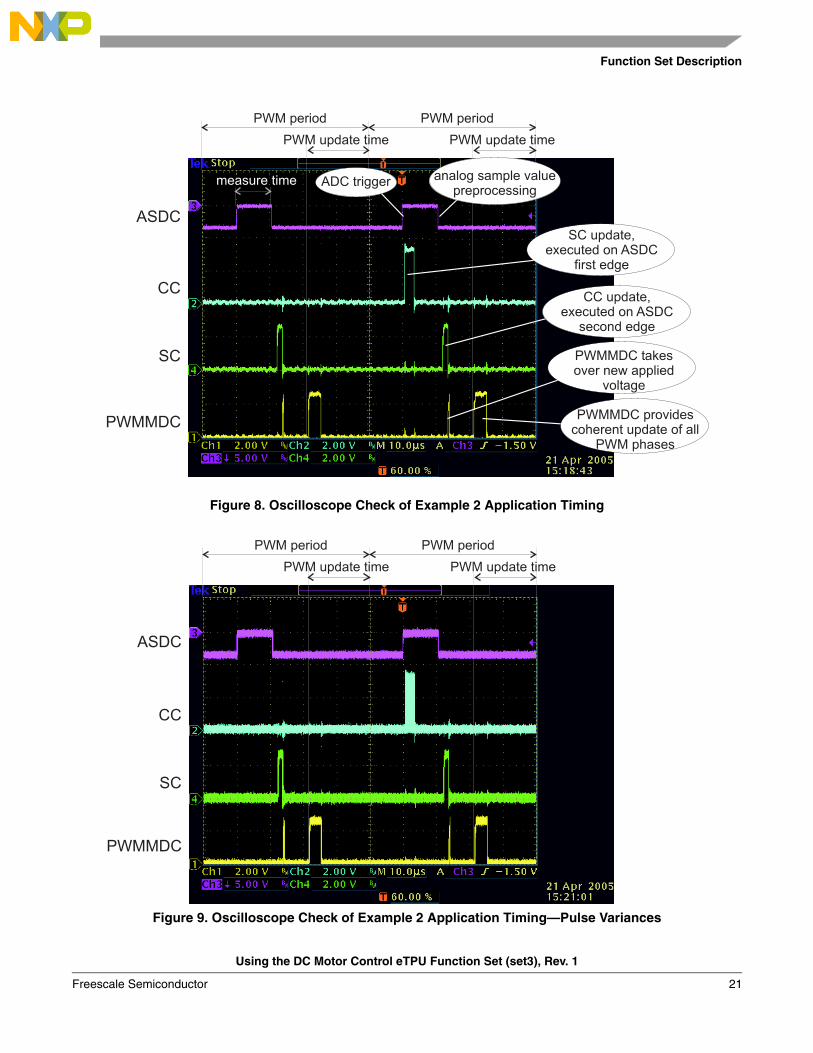
The described timing configuration is shown in Figure 5.
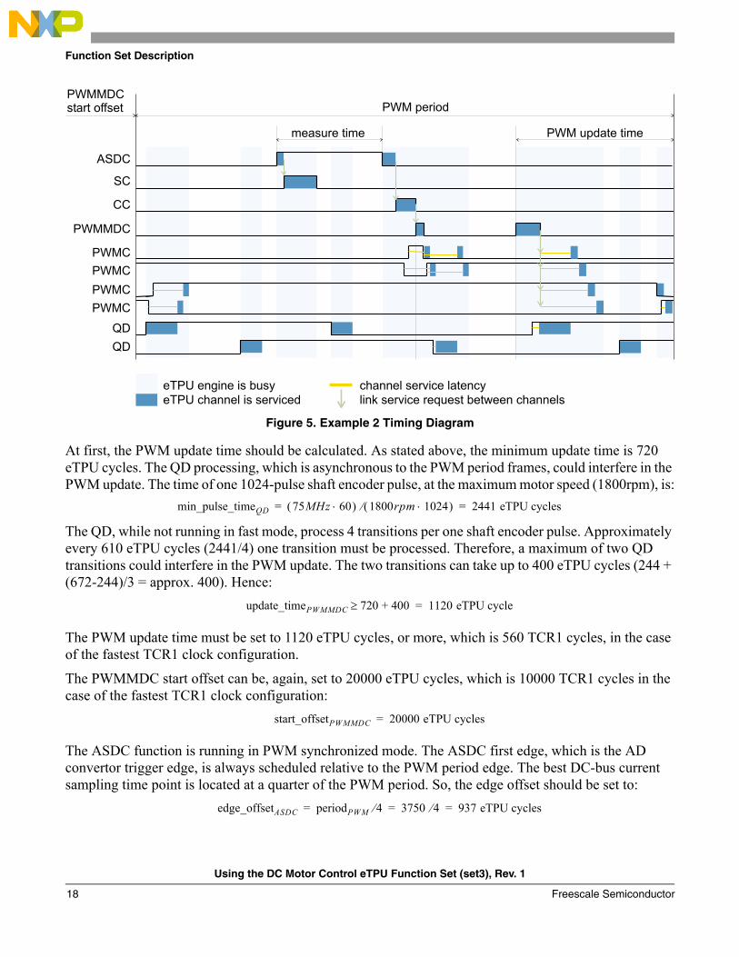
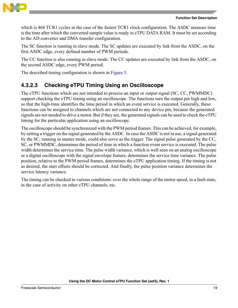
4.3.2.3 Checking eTPU Timing Using an OscilloscopeThe eTPU functions which are not intended to process an input or output signal (SC, CC, PWMMDC) support checking the eTPU timing using an oscilloscope. The functions turn the output pin high and low, so that the high-time identifies the time period in which an event service is executed. Generally, these functions can be assigned to channels which are not connected to any device pin, because the generated signals are not needed to drive a motor. But if they are, the generated signals can be used to check the eTPU timing for the particular application using an oscilloscope.
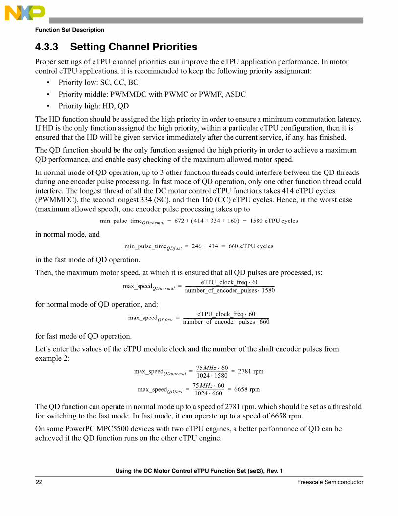
The oscilloscope should be synchronized with the PWM period frames. This can be achieved, for example, by setting a trigger on the signal generated by the ASDC. In case the ASDC is not in use, a signal generated by the SC, running in master mode, could also serve as the trigger. The signal pulse generated by the CC, SC, or PWMMDC, determines the period of time in which a function event service is executed. The pulse width determines the service time. The pulse width variance, which is well seen on an analog oscilloscope or a digital oscilloscope with the signal envelope feature, determines the service time variance. The pulse position, relative to the PWM period frames, determines the eTPU application timing. If the timing is not as desired, the start offsets should be corrected. And finally, the pulse position variance determines the service latency variance.
The timing can be checked in various conditions: over the whole range of the motor speed, in a fault state, in the case of activity on other eTPU channels, etc.
Using the DC Motor Control eTPU Function Set (set3), Rev. 1
Freescale Semiconductor 19
Function Set Description
Figure 6. Oscilloscope Check of Example 1 Application Timing
Figure 7. Oscilloscope Check of Example 1 Application Timing—Pulse Variances
PWM period PWM period
PWM update time
SCSC update
PWM update time
PWMMDC
PWMMDC takesover new applied
voltage
PWMMDC providescoherent update of all
PWM phasesPWMMDC
does not updatePWM phases
PWMMDC
SC
PWM period PWM period
PWM update timePWM update time
Using the DC Motor Control eTPU Function Set (set3), Rev. 1
Freescale Semiconductor20
Function Set Description
Figure 8. Oscilloscope Check of Example 2 Application Timing
Figure 9. Oscilloscope Check of Example 2 Application Timing—Pulse Variances
ASDC
SC
CC
PWMMDC
PWM period PWM period
PWM update time
measure time
SC update,executed on ASDC
first edge
CC update,executed on ASDC
second edge
PWMMDC takesover new applied
voltage
PWMMDC providescoherent update of all
PWM phases
ADC trigger analog sample valuepreprocessing
PWM update time
ASDC
SC
CC
PWMMDC
PWM period PWM period
PWM update timePWM update time
Using the DC Motor Control eTPU Function Set (set3), Rev. 1
Freescale Semiconductor 21
Function Set Description
4.3.3 Setting Channel PrioritiesProper settings of eTPU channel priorities can improve the eTPU application performance. In motor control eTPU applications, it is recommended to keep the following priority assignment:
• Priority low: SC, CC, BC• Priority middle: PWMMDC with PWMC or PWMF, ASDC• Priority high: HD, QD
The HD function should be assigned the high priority in order to ensure a minimum commutation latency. If HD is the only function assigned the high priority, within a particular eTPU configuration, then it is ensured that the HD will be given service immediately after the current service, if any, has finished.
The QD function should be the only function assigned the high priority in order to achieve a maximum QD performance, and enable easy checking of the maximum allowed motor speed.
In normal mode of QD operation, up to 3 other function threads could interfere between the QD threads during one encoder pulse processing. In fast mode of QD operation, only one other function thread could interfere. The longest thread of all the DC motor control eTPU functions takes 414 eTPU cycles (PWMMDC), the second longest 334 (SC), and then 160 (CC) eTPU cycles. Hence, in the worst case (maximum allowed speed), one encoder pulse processing takes up to
in normal mode, and
in the fast mode of QD operation.
Then, the maximum motor speed, at which it is ensured that all QD pulses are processed, is:
for normal mode of QD operation, and:
for fast mode of QD operation.
Let’s enter the values of the eTPU module clock and the number of the shaft encoder pulses from example 2:
The QD function can operate in normal mode up to a speed of 2781 rpm, which should be set as a threshold for switching to the fast mode. In fast mode, it can operate up to a speed of 6658 rpm.
On some PowerPC MPC5500 devices with two eTPU engines, a better performance of QD can be achieved if the QD function runs on the other eTPU engine.
min_pulse_timeQDnormal 672 414 334 160+ +( )+ 1580 eTPU cycles= =
min_pulse_timeQDfast 246 414+ 660 eTPU cycles= =
max_speedQDnormaleTPU_clock_freq 60⋅
number_of_encoder_pulses 1580⋅----------------------------------------------------------------------------------=
max_speedQDfasteTPU_clock_freq 60⋅
number_of_encoder_pulses 660⋅-------------------------------------------------------------------------------=
max_speedQDnormal75MHz 60⋅1024 1580⋅----------------------------- 2781 rpm= =
max_speedQDfast75MHz 60⋅1024 660⋅
----------------------------- 6658 rpm= =
Using the DC Motor Control eTPU Function Set (set3), Rev. 1
Freescale Semiconductor22
Summary and Conclusions
5 Summary and ConclusionsThis application note provides the user with a description of the DC motor control eTPU function set (set3), and its usage in applications.
References:• eTPU General:1. “The Essentials of Enhanced Time Processing Unit,” AN2353.2. “General C Functions for the eTPU,” AN2864.3. Enhanced Time Processing Unit Reference Manual, ETPURM/D.4. eTPU Graphical Configuration Tool, http://www.freescale.com/etpu, ETPUGCT.• eTPU Functions:5. “Using the General Purpose Input/Output (GPIO) eTPU Function,” AN2850.6. “Using the DC Motor Control PWM eTPU Functions,” AN2840.7. “Using the Hall Decoder (HD) eTPU Function,” AN2841.8. “Using the Quadrature Decoder (QD) eTPU Function,” AN2842.9. “Using the Speed Controller (SC) eTPU Function,” AN2843.10. “Using the Current Controller (CC) eTPU Function,” AN2844.11. “Using the Break Controller (BC) eTPU Function,” AN2845.12. “Using the Analog Sensing for DC Motors (ASDC) eTPU Function,” AN2846.• eTPU Demo Applications:13. “BLDC Motor with Hall Sensors and Speed Closed Loop, driven by eTPU on MCF523x,”
AN2892.14. “BLDC Motor with Hall Sensors, Speed Closed Loop and DC-Bus Break Controller, driven by
eTPU on MCF523x,” AN2954.15. “DC Motor with Speed and Current Closed Loop, driven by eTPU on MCF523x,” AN2955.16. “BLDC Motor with Quadrature Encoder and Speed Closed Loop, driven by eTPU on MCF523x,”
AN2957.17. “BLDC Motor with Hall Sensors and Speed Closed Loop, driven by eTPU on MPC5554,”
AN3006.18. “BLDC Motor with Hall Sensors, Speed Closed Loop and DC-Bus Break Controller, driven by
eTPU on MPC5554,” AN3007.19. “DC Motor with Speed and Current Closed Loop, driven by eTPU on MPC5554,” AN3008.20. “BLDC Motor with Quadrature Encoder and Speed Closed Loop, driven by eTPU on MPC5554,”
AN3005.
Using the DC Motor Control eTPU Function Set (set3), Rev. 1
Freescale Semiconductor 23
How to Reach Us:
Home Page:www.freescale.com
E-mail:[email protected]
USA/Europe or Locations Not Listed:Freescale SemiconductorTechnical Information Center, CH3701300 N. Alma School RoadChandler, Arizona 85224+1-800-521-6274 or [email protected]
Europe, Middle East, and Africa:Freescale Halbleiter Deutschland GmbHTechnical Information CenterSchatzbogen 781829 Muenchen, Germany+44 1296 380 456 (English)+46 8 52200080 (English)+49 89 92103 559 (German)+33 1 69 35 48 48 (French)[email protected]
Japan:Freescale Semiconductor Japan Ltd.HeadquartersARCO Tower 15F1-8-1, Shimo-Meguro, Meguro-ku,Tokyo 153-0064, Japan0120 191014 or +81 3 5437 [email protected]
Asia/Pacific:Freescale Semiconductor Hong Kong Ltd.Technical Information Center2 Dai King StreetTai Po Industrial EstateTai Po, N.T., Hong Kong+800 2666 [email protected]
For Literature Requests Only:Freescale Semiconductor Literature Distribution CenterP.O. Box 5405Denver, Colorado 802171-800-441-2447 or 303-675-2140Fax: [email protected]
Information in this document is provided solely to enable system and software implementers to use Freescale Semiconductor products. There are no express or implied copyright licenses granted hereunder to design or fabricate any integrated circuits or integrated circuits based on the information in this document.
Freescale Semiconductor reserves the right to make changes without further notice to any products herein. Freescale Semiconductor makes no warranty, representation or guarantee regarding the suitability of its products for any particular purpose, nor does Freescale Semiconductor assume any liability arising out of the application or use of any product or circuit, and specifically disclaims any and all liability, including without limitation consequential or incidental damages. “Typical” parameters that may be provided in Freescale Semiconductor data sheets and/or specifications can and do vary in different applications and actual performance may vary over time. All operating parameters, including “Typicals”, must be validated for each customer application by customer’s technical experts. Freescale Semiconductor does not convey any license under its patent rights nor the rights of others. Freescale Semiconductor products are not designed, intended, or authorized for use as components in systems intended for surgical implant into the body, or other applications intended to support or sustain life, or for any other application in which the failure of the Freescale Semiconductor product could create a situation where personal injury or death may occur. Should Buyer purchase or use Freescale Semiconductor products for any such unintended or unauthorized application, Buyer shall indemnify and hold Freescale Semiconductor and its officers, employees, subsidiaries, affiliates, and distributors harmless against all claims, costs, damages, and expenses, and reasonable attorney fees arising out of, directly or indirectly, any claim of personal injury or death associated with such unintended or unauthorized use, even if such claim alleges that Freescale Semiconductor was negligent regarding the design or manufacture of the part.
Freescale™ and the Freescale logo are trademarks of Freescale Semiconductor, Inc. All other product or service names are the propertyof their respective owners.© Freescale Semiconductor, Inc. 2004. All rights reserved.
AN2958Rev. 105/2006