AN2655 - LAN9252 SDK Firmware API...
32
2018 Microchip Technology Inc. DS00002655A-page 1 1.0 INTRODUCTION This document describes the firmware APIs used to integrate the Microchip LAN9252 EtherCAT ® slave controller (ESC) with PIC32MX, which assist developers porting their EtherCAT slave stack application with LAN9252. 1.1 Terms and Abbreviations • ETG - EtherCAT ® Technology Group • ESC - EtherCAT ® Slave Controller • EVB - Engineering Validation Board • HAL - Hardware Abstraction Layer • HBI - Host Bus Interface • IDE - Integrated Development Environment • PDI - Process Data Interface • SDK - Software Development Kit • SPI - Serial Protocol Interface • SQI - Serial Quad Interface • SSC - Slave Stack Code 1.2 References The following documents should be referenced when using this application note. See your Microchip representative for availability. • LAN9252 Data Sheet • AN1907 - Microchip LAN9252 Migration from Beckhoff ET1100 • AN1916 - AN1916 Integrating Microchip's LAN9252 SDK with Beckhoff's EtherCAT ® SSC • AN1995 - LAN9252 SOC Porting Guidelines • EtherCAT Slave Stack Code (SSC) ET9300 - www.ethercat.org AN2655 LAN9252 SDK Firmware API Guide Author: Riyas Kattukandan Microchip Technology Inc.
Transcript of AN2655 - LAN9252 SDK Firmware API...

AN2655LAN9252 SDK Firmware API Guide
1.0 INTRODUCTION
This document describes the firmware APIs used to integrate the Microchip LAN9252 EtherCAT® slave controller (ESC)with PIC32MX, which assist developers porting their EtherCAT slave stack application with LAN9252.
1.1 Terms and Abbreviations
• ETG - EtherCAT® Technology Group
• ESC - EtherCAT® Slave Controller
• EVB - Engineering Validation Board
• HAL - Hardware Abstraction Layer
• HBI - Host Bus Interface
• IDE - Integrated Development Environment
• PDI - Process Data Interface
• SDK - Software Development Kit
• SPI - Serial Protocol Interface
• SQI - Serial Quad Interface
• SSC - Slave Stack Code
1.2 References
The following documents should be referenced when using this application note. See your Microchip representative foravailability.
• LAN9252 Data Sheet
• AN1907 - Microchip LAN9252 Migration from Beckhoff ET1100
• AN1916 - AN1916 Integrating Microchip's LAN9252 SDK with Beckhoff's EtherCAT ®SSC
• AN1995 - LAN9252 SOC Porting Guidelines
• EtherCAT Slave Stack Code (SSC) ET9300 - www.ethercat.org
Author: Riyas KattukandanMicrochip Technology Inc.
2018 Microchip Technology Inc. DS00002655A-page 1

AN2655
2.0 LAN9252 GENERAL DESCRIPTION
The LAN9252 is a 2/3-port EtherCAT slave controller with dual integrated Ethernet PHYs that each contain a full-duplex100BASE-TX transceiver and support 100-Mbps (100BASE-TX) operation.
LAN9252-based solutions can be implemented in the following modes:
Microcontroller Mode: The LAN9252 communicates with the microcontroller through an SRAM-like slave interface.The simple, yet highly functional host bus interface provides a glue-less connection to most common 8- or 16-bit micro-processors and microcontrollers, as well as 32-bit microprocessors with an 8- or 16-bit external bus.
Alternatively, the device can be accessed via SPI or Quad SPI, while also providing up to 16 inputs or outputs for generalpurpose usage.
Expansion Mode: While the device is in SPI or Quad SPI mode, a third networking port can be enabled to provide anadditional MII port. This port can be connected to an external PHY to enable star or tree network topologies, or con-nected to another LAN9252 to create a four-port solution. This port can be configured for the upstream or downstreamdirection.
Digital I/O Mode: For simple digital modules without microcontrollers, the LAN9252 can operate in Digital I/O Modewhere 16 digital signals can be controlled or monitored by the EtherCAT master. Six control signals are also provided.
FIGURE 2-1: LAN9252 BLOCK DIAGRAM
LAN9252
EtherCAT® Slave Controller
Loopback
Loopback
Loopback
AutoForwarder
AutoForwarder
AutoForwarder
Port 0Port 0
Port 2Port 1
Registers/RAM
ESC Address Space
SyncManager
FMMU
Parallel Data Interface
LED Controller
I2C EEPROM
System Interrupt
Controller
System Clocks/Reset Controller
100 PHY w/ fiber
Registers
100 PHY w/ fiber
Registers
To 8-/16-bitHost Bus,MII, SPI,Digital IOs,GPIOs
Ethernet
Ethernet
To optional LEDs To I2C IRQExternal
25-MHz Crystal
DS00002655A-page 2 2018 Microchip Technology Inc.
AN2655
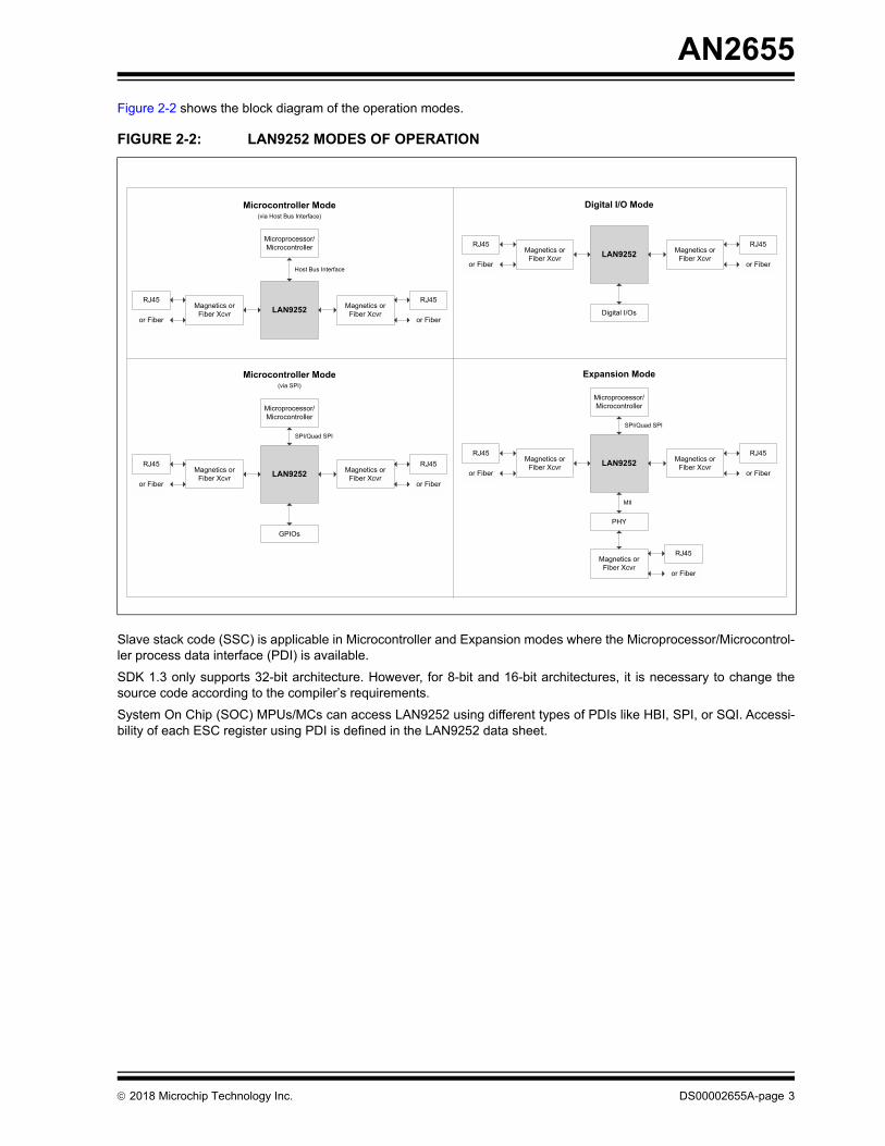
Figure 2-2 shows the block diagram of the operation modes.
Slave stack code (SSC) is applicable in Microcontroller and Expansion modes where the Microprocessor/Microcontrol-ler process data interface (PDI) is available.
SDK 1.3 only supports 32-bit architecture. However, for 8-bit and 16-bit architectures, it is necessary to change thesource code according to the compiler’s requirements.
System On Chip (SOC) MPUs/MCs can access LAN9252 using different types of PDIs like HBI, SPI, or SQI. Accessi-bility of each ESC register using PDI is defined in the LAN9252 data sheet.
FIGURE 2-2: LAN9252 MODES OF OPERATION
Magnetics or Fiber Xcvr LAN9252 Magnetics or
Fiber Xcvr
RJ45
or Fiber
RJ45
or Fiber
Microprocessor/Microcontroller
Host Bus Interface
Microcontroller Mode(via Host Bus Interface)
Digital I/O Mode
Magnetics or Fiber Xcvr LAN9252 Magnetics or
Fiber Xcvr
RJ45
or Fiber
RJ45
or Fiber
Digital I/Os
Magnetics or Fiber Xcvr LAN9252 Magnetics or
Fiber Xcvr
RJ45
or Fiber
RJ45
or Fiber
Microprocessor/Microcontroller
SPI/Quad SPI
Microcontroller Mode(via SPI)
GPIOs
Magnetics or Fiber Xcvr LAN9252 Magnetics or
Fiber Xcvr
RJ45
or Fiber
RJ45
or Fiber
Microprocessor/Microcontroller
SPI/Quad SPI
Expansion Mode
PHY
MII
Magnetics or Fiber Xcvr
RJ45
or Fiber
2018 Microchip Technology Inc. DS00002655A-page 3

AN2655
2.1 LAN9252 Register Classification
There are two types of registers available in the LAN9252:
• Directly accessible registers (LAN9252 Control and Status Registers (CSR))
• Indirectly accessible registers – (EtherCAT Status and Control registers - ESC). All EtherCAT core registers reside under this group. The application can read and write EtherCAT core registers using LAN9252 CSR registers.
Note: Refer to the LAN9252 data sheet for a more detailed description of each register.
2.2 Interrupts
All interrupts must be configured during hardware initialization. Since SSC accesses ESC registers from both interruptcontext and polling mode, ECAT_CSR_CMD and ECAT_CSR_DATA registers must be protected; otherwise, it may cor-rupt the SSC state machine routines.
For example, if an interrupt fires during reading of 0x120 (ESC) register under polling mode, soon after updating 0x120(Address) into the ECAT_CSR_CMD register, then any ESC access (read/write) from the interrupt routine overwritesthe ECAT_CSR_CMD register (some other address, for example, 0x220), which overrides the ECAT_CSR_DATA reg-ister.
Corruption of data because of interrupt fire can be avoided by disabling the interrupt routine while accessing any ESCregisters. However, any missed interrupts because of disabling the interrupts can be monitored by the interrupt line(GPIO) after reading/writing EtherCAT core register.
Interrupt handler in SDK 1.x must be modified according to the host SOC/C.
TABLE 2-1: SYSTEM CONTROLS AND STATUS REGISTERS
Address Register Name (Symbol)
000h-01Ch EtherCAT Process RAM Read Data FIFO (ECAT_PRAM_RD_DATA)
020h-03Ch EtherCAT Process RAM Write Data FIFO (ECAT_PRAM_WR_DATA)
050h Chip ID and Revision (ID_REV)
054h Interrupt Configuration Register (IRQ_CFG)
058h Interrupt Status Register (INT_STS)
05Ch Interrupt Enable Register (INT_EN)
064h Byte Order Test Register (BYTE_TEST)
074h Hardware Configuration Register (HW_CFG)
084h Power Management Control Register (PMT_CTRL)
08Ch General Purpose Timer Configuration Register (GPT_CFG)
090h General Purpose Timer Count Register (GPT_CNT)
09Ch Free Running 25MHz Counter Register (FREE_RUN)
Reset Register
1F8h Reset Control Register (RESET_CTL)
EtherCAT Registers
300h EtherCAT CSR Interface Data Register (ECAT_CSR_DATA)
304h EtherCAT CSR Interface Command Register (ECAT_CSR_CMD)
308h EtherCAT Process RAM Read Address and Length Register (ECAT_PRAM_RD_ADDR_LEN)
30Ch EtherCAT Process RAM Read Command Register (ECAT_PRAM_RD_CMD)
310h EtherCAT Process RAM Write Address and Length Register (ECAT_PRAM_WR_ADDR_LEN)
314h EtherCAT Process RAM Write Command Register (ECAT_PRAM_WR_CMD)
DS00002655A-page 4 2018 Microchip Technology Inc.

AN2655
2.2.1 PDI INTERRUPT
The programmable system interrupts are generated internally by various device sub-modules and can be configured togenerate a single external host interrupt via the IRQ interrupt output pin. The programmable nature of the host interruptprovides the user with the ability to optimize performance dependent upon the application requirements. Buffer type,polarity, and deassertion interval of the IRQ interrupt are modifiable. The IRQ interrupt can be configured as an open-drain output to facilitate the sharing of interrupts with other devices. All internal interrupts are maskable and capable oftriggering the IRQ interrupt.
If the application running on the SOC requires AL Event Interrupt, then the IRQ line should be connected to the micro-controller input interrupt. The configuration of IRQ can be done using INTERRUPT CONFIGURATION REGISTER(IRQ_CFG) - 0x54 and INTERRUPT ENABLE REGISTER (INT_EN) - 0x5C. For more details, refer to the LAN9252data sheet.
2.2.2 DC - SYNC0 AND SYNC1
If the application running on the SOC requires a Distributed Clock (DC), then SYNC0 and SYNC1 should be connectedto the interrupts lines of the microcontroller. Refer to the LAN9252 data sheet for the configuration of SYNC0 andSYNC1.
2.2.3 TIMER
SSC has a variable that counts every one millisecond, which can be implemented either using timer interrupt or pollingmethod. The interrupt or polling mode can be selected in the SSC Tool before generating the SSC.
FIGURE 2-3: FUNCTIONAL INTERRUPT MECHANISM
EtherCAT® Device
DC
SYNC/LatchPDI Config.
Register
(0x0151)
&
&
Other Interrupt sources
AL Event Request Register
(0x0220:0x0223)
AL Event Mask
Register
(0x0204:0x0207)
& ≥ 1
SYNC0
SYNC1
SYNC0
SYNC1
IRQ
IRQ_B
IRQ_C
IRQ_A
8
3
7
2
3
32 32
32
32
PDI Interface
(SPI, SQI, or H
BI)
Controller
2018 Microchip Technology Inc. DS00002655A-page 5

AN2655
3.0 LAN9252 SDK 1.X
The PDI and hardware-specific files are part of the LAN9252 SDK 1.x. The user application, aoeappl, coeappl, foeappl,and eoeappl have to be defined as per user applications. The PDI interface in SDK 1.3 is based on PIC32MX795F512L.Thus, for any other SOCs, these files must be modified.
SDK 1.3 has two root folders:
• Common - The SSC tool generated files can be copied here. The LAN9252_HW has generic PDI APIs defined as per ET9300. This can be easily ported to any other architec-ture.
• PIC32 - This folder contains the APIs that are platform-dependent. For controllers other than PIC32MX795F512L, all the APIs must be ported as per the SOCs used.
PMPDriver has the HBI driver (PIC32MX PMP driver) files, whereas SPIDriver has the APIsrelated to PIC32MX SPI related APIs.
PICHW has the platform-dependent APIs that are defined by ET9300.
FIGURE 3-1: SSC OVERVIEW
Note: For more information about the SSC tool, refer to EtherCAT Slave Stack Code (SSC) ET9300 web page(www.ethercat.org).
State machine (ecatslv.*) Process data (ecatappl.*) Mailbox (mailbox.*)
Emer
genc
y (e
mcy
.*)
AoE
(eca
taoe
.*)
CoE
(eca
tcoe
.*)
FoE
(eca
tfoe.
*)
EoE
(eca
teoe
.*)
SoE
(eca
tsoe
.*)
VoE
Cod
e co
nfig
urat
ion
(eca
t_de
f.h)
aoea
ppl.*
sdos
erv.
*ob
jdef
.*co
eapp
l.*
foea
ppl.*
eoea
ppl.*
Process data interface (PDI) and hardware specific files (XXXXhw.*)
ESC
PDI
IRQ
DL
AL
User application (el9800appl.*, cia402appl.*, …)
DS00002655A-page 6 2018 Microchip Technology Inc.

AN2655
4.0 LAN9252 HARDWARE ABSTRACTION LAYER
The functions to be defined to integrate with SSC as per ET9300 are:
• UINT8 HW_Init(void);
• void HW_Release(void);
• UINT16 HW_GetALEventRegister(void);
• UINT16 HW_GetALEventRegister_Isr(void);
• void HW_ResetALEventMask(UINT16 intMask);
• void HW_SetALEventMask(UINT16 intMask);
• void HW_EscRead( MEM_ADDR * pData, UINT16 Address, UINT16 Len );
• void HW_EscReadIsr( MEM_ADDR *pData, UINT16 Address, UINT16 Len );
• void HW_EscWrite( MEM_ADDR *pData, UINT16 Address, UINT16 Len );
• void HW_EscWriteIsr( MEM_ADDR *pData, UINT16 Address, UINT16 Len );
• void HW_EscReadMbxMem(MEM_ADDR *pData, UINT16 Address, UINT16 Len )
• void HW_EscWriteMbxMem(MEM_ADDR *pData, UINT16 Address, UINT16 Len )
• void HW_DisableSyncManChannel(UINT8 channel);
• void HW_EnableSyncManChannel(UINT8 channel);
• TSYNCMAN ESCMEM *HW_GetSyncMan(UINT8 channel);
• UINT16 MainInit(void)
• void MainLoop(void)
• Interrupts for IRQ, SYNC0 and SYNC1
• Timer Interrupt
2018 Microchip Technology Inc. DS00002655A-page 7

AN2655
5.0 LAN9252 SDK APIS
Refer to the ET9300 application note and the SSC tool from ETG for more details about generating the SSC code. SSCdefines predefined macros to create appropriate settings for creating the source code for any companion ESCs andSOCs. Table 5-1 has some example macros.
The Microchip_LAN9252_SSC_Config.xml has the predefined macros that are required for generating the SSC codewith respect to LAN9252 ESC.
The SSC consists of three parts:
• PDI/HAL
- Generic LAN9252 driver
- Low-level PDI driver (specific to host uController)
• Generic EtherCAT stack
• User application
The behavior of the generic EtherCAT stack is described in ETG.1000 Specification [2]. In general, the hardware accessimplementation needs to support the following features:
• ESC read/write access
• Timer supply (at least 1 ms base tick)
TABLE 5-1: EXAMPLES OF SSC PREDEFINED MACROS
Macro Description
CONTROLLER_16BIT This setting is used if the slave code is built for a 16-bit C.
CONTROLLER_32BIT This setting is used if the slave code is built for a 32-bit C.
ESC_16BIT_ACCESS If this setting is set, then only 16-bit aligned accesses will be performed on the ESC.
ESC_32BIT_ACCESS If this setting is set, then only 32-bit aligned accesses will be performed on the ESC.
MBX_16BIT_ACCESS If this setting is set, then the slave code will only access mailbox data 16-bit aligned. If the mailbox data is copied to the local μC memory and CONTROLLER_16BIT is set, then this definition should also be set.
FIGURE 5-1: SSC FUNCTIONAL HIERARCHY
Application(for example, CiA402 Drive Profile)
EtherCAT® State Machine
AoE
FoE
EoE
SoE
VoE
CoE
Mailbox
Process data
PDI and hardware abstraction
Application function set
Hardware function set
ESC address space (DPRAM)
Mailbox Process data
Register0x10000x0000
UserApplication
GenericEtherCAT® stack
Hardware access
EtherCAT® Slave Controller (extract)
DS00002655A-page 8 2018 Microchip Technology Inc.

AN2655
• Calling of timer handler every 1 ms (only required if timer interrupt handling is supported; ECAT_TIMER_INT is set to 1)
• Calling of interrupt specific functions (only required if synchronization is supported)
- PDI ISR (required if AL_EVENT_SUPPORTED is set to 1)
- SYNC0 ISR (required if DC_SUPPORTED is set to 1)
The functions and macros that should be provided by the HAL to access LAN9252 and the function that should be pro-vided by the application layer are defined in the following sections.
5.1 LAN9252 Driver
As per the ET9300 application note (EtherCAT Slave Stack Code), the hardware access APIs need to access GenericEtherCAT stack as follows.
5.1.1 HW_INIT
This function should call from the slave project for initialization of ESC. This function is replaced by UINT16LAN9252_Init(void).
5.1.2 LAN9252_INIT
This function should call from the slave project for initialization of ESC. Before calling this function, the PDI interface ofthe slave microcontroller should be initialized.
For initialization of LAN9252, read BYTE-ORDER register (0x64) until it reads 0x87654321. Enable AL Event maskingof the AL Event Request register events for mapping to PDI IRQ signal (set 0x93).
This function initializes the LAN9252 PDI interface, configures the LAN9252 IRQ polarity, and provides a function toenable various interrupts, IRQ, SYNC, and Timer.
• PDI_Init_SYNC_Interrupts() - Configure and enable SYNC interrupt
• PDI_Timer_Interrupt() - Configure and enable Timer interrupt
• PDI_IRQ_Interrupt() - Configure and enable IRQ interrupt
• PDI_Enable_Global_interrupt() - Global interrupt
These functions depend on the slave microcontroller.
Refer to the “Interrupt Registers” section of the LAN9252 data sheet.
5.1.3 HW_RELEASE
This function is implemented if hardware resources must be released when the sample application stops.
Prototype UINT16 HW_Init(void)
Parameter void
Return 0 if initialization was successful
> 0 if error has occurred while initialization
Description Initializes the host controller (PDI) and allocates resources that are required for hardware access.
Prototype UINT16 LAN9252_Init(void)
Parameter void
Return 0 if initialization was successful
> 0 if error has occurred while initialization
Description Initializes the host controller (PDI) and allocates resources that are required for hardware access.
Prototype void HW_Release(void)
Parameter void
Return void
Description Release allocated resources
2018 Microchip Technology Inc. DS00002655A-page 9
AN2655
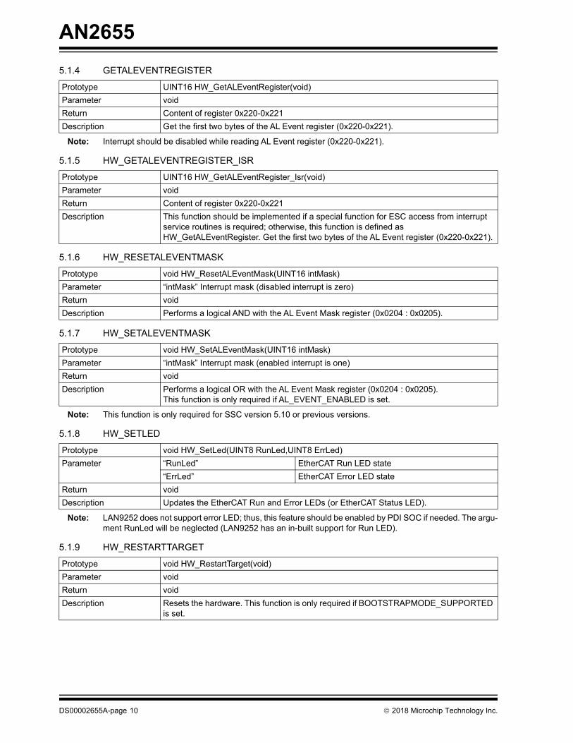
5.1.4 GETALEVENTREGISTER
Note: Interrupt should be disabled while reading AL Event register (0x220-0x221).
5.1.5 HW_GETALEVENTREGISTER_ISR
5.1.6 HW_RESETALEVENTMASK
5.1.7 HW_SETALEVENTMASK
Note: This function is only required for SSC version 5.10 or previous versions.
5.1.8 HW_SETLED
Note: LAN9252 does not support error LED; thus, this feature should be enabled by PDI SOC if needed. The argu-ment RunLed will be neglected (LAN9252 has an in-built support for Run LED).
5.1.9 HW_RESTARTTARGET
Prototype UINT16 HW_GetALEventRegister(void)
Parameter void
Return Content of register 0x220-0x221
Description Get the first two bytes of the AL Event register (0x220-0x221).
Prototype UINT16 HW_GetALEventRegister_Isr(void)
Parameter void
Return Content of register 0x220-0x221
Description This function should be implemented if a special function for ESC access from interrupt service routines is required; otherwise, this function is defined as HW_GetALEventRegister. Get the first two bytes of the AL Event register (0x220-0x221).
Prototype void HW_ResetALEventMask(UINT16 intMask)
Parameter “intMask” Interrupt mask (disabled interrupt is zero)
Return void
Description Performs a logical AND with the AL Event Mask register (0x0204 : 0x0205).
Prototype void HW_SetALEventMask(UINT16 intMask)
Parameter “intMask” Interrupt mask (enabled interrupt is one)
Return void
Description Performs a logical OR with the AL Event Mask register (0x0204 : 0x0205).This function is only required if AL_EVENT_ENABLED is set.
Prototype void HW_SetLed(UINT8 RunLed,UINT8 ErrLed)
Parameter “RunLed” EtherCAT Run LED state
“ErrLed” EtherCAT Error LED state
Return void
Description Updates the EtherCAT Run and Error LEDs (or EtherCAT Status LED).
Prototype void HW_RestartTarget(void)
Parameter void
Return void
Description Resets the hardware. This function is only required if BOOTSTRAPMODE_SUPPORTED is set.
DS00002655A-page 10 2018 Microchip Technology Inc.

AN2655
5.1.10 HW_DISABLESYNCMANCHANNEL
Find the sync manager offset register for the corresponding “channel” and disable it.
Note: This function is not supported. This function is only required for SSC version 5.10 or previous versions.
5.1.11 HW_ENABLESYNCMANCHANNEL
Find the sync manager offset register for the corresponding “channel” and disable it.
Note: This function is not supported. This function is only required for SSC version 5.10 or previous versions.
5.1.12 HW_GETSYNCMAN
Note: This function is not supported. This function is only required for SSC version 5.10 or previous versions.
5.1.13 HW_GETTIMER
This function provides the “PDI_GetTimer()” function to get the current hardware timer value. ECAT_TIMER_INC_P_MSmust be defined as per slave microcontroller implementation. SSC calculates different timeouts as per the hardwaretime ticks and ECAT_TIMER_INC_P_MS.
Note: This function is required if no timer interrupt is supported (ECAT_TIMER_INT = 0) and to calculate the buscycle time.
5.1.14 HW_CLEARTIMER
This function provides the “PDI_ClearTimer” function to clear the hardware timer value.
5.1.15 HW_EEPROMRELOAD
This is only required if EEPROM Emulation is supported. LAN9252 does not support EEPROM Emulation.
Prototype void HW_DisableSyncManChannel(UINT8 channel)
Parameter “channel” SyncManager channel
Return void
Description Disables selected SyncManager channel. Sets bit 0 of the corresponding register.
Prototype void HW_EnableSyncManChannel (UINT8 channel)
Parameter “channel” SyncManager channel
Return void
Description Enables selected SyncManager channel. Resets bit 0 of the corresponding 0x807 regis-ter.
Prototype TSYNCMAN * HW_GetSyncMan(UINT8 channel)
Parameter “channel” SyncManager channel
Return Pointer to the SyncManager channel description. The SyncManager description structure size is always 8 byte; the content of TSYNCMAN differs depending on the supported ESC access.
Description Gets the content of the SyncManager register from the stated channel. Reads 8 bytes starting at 0x800 + 8*channel.
Prototype UINT32 HW_GetTimer(void)
Parameter void
Return Current timer value
Description Reads the current register value of the hardware timer. If no hardware timer is available, the function returns the counter value of a multimedia timer. The timer ticks value (incre-ments/ms) is defined in ECAT_TIMER_INC_P_MS.
Prototype void HW_ClearTimer(void)
Parameter void
Return void
Description Clears the hardware timer value.
2018 Microchip Technology Inc. DS00002655A-page 11

AN2655
5.1.16 READ/WRITE ACCESS
The EtherCAT CSRs provide register level access to the various parameters of the EtherCAT core. LAN9252-relatedregisters can be classified into two categories based on their method of access: direct and indirect.
The directly accessible registers (EtherCAT CSR and Process Data RAM Access Registers) are part of the main systemCSRs (LAN9252). These registers provide data or command registers for access to the indirect EtherCAT core regis-ters. Refer to the “EtherCAT CSR and Process Data RAM Access Registers (Directly Addressable)” section of theLAN9252 data sheet for more details.
The indirectly accessible EtherCAT core registers reside within the EtherCAT core and must be accessed indirectly viathe EtherCAT CSR Interface Data Register (ECAT_CSR_DATA) and EtherCAT CSR Interface Command Register(ECAT_CSR_CMD). The indirectly accessible EtherCAT core CSRs provide full access to the many configurableparameters of the EtherCAT core. The indirectly accessible EtherCAT core CSRs are accessed at address 0h through0FFFh and are detailed in the “EtherCAT Core CSR Registers (Indirectly Addressable)” section of the LAN9252 datasheet.
The EtherCAT Core Process Data RAM can be accessed indirectly via ECAT_CSR_DATA and ECAT_CSR_CMD, start-ing at 1000h.
The EtherCAT Core Process Data RAM can also be accessed more efficiently using the EtherCAT Process RAM ReadData FIFO (ECAT_PRAM_RD_DATA) and EtherCAT Process RAM Write Data FIFO (ECAT_PRAM_WR_DATA). Thismethod provides for multiple DWORDS to be transferred via a FIFO mechanism using a single command and fewerstatus reads.
For more details, refer to the “ETHERCAT PROCESS RAM READS” and “ETHERCAT PROCESS RAM WRITES” sec-tions of the LAN9252 data sheet.
5.1.16.1 HW_EscRead
This API provides the PDIReadReg() function to access the ESC core register and Process RAM. The implementationof this API depends on the PDI interface and slave microcontroller method to access LAN9252 registers (for example,DMA or accessing the data buffers).
Note: To protect the CSR command and data register (a read or write event from interrupt routine overwrites theCSR command and data register), the interrupt has to be disabled before accessing any ESC memory.
Prototype void HW_EscRead(MEM_ADDR *pData, UINT16 Address, UINT16 Len )
Parameter “pData” Pointer to local destination buffer. The type of pointer depends on the host controller architecture (specified in ecat_def.h or the SSC Tool).
“Address” EtherCAT Slave Controller address. Specifies the off-set within the ESC memory area in bytes. Only valid addresses are used depending on 8-/16-bit or 32-bit ESC access (specified in ecat_def.h or the SSC Tool).
“Len” Access size in bytes
Return void
Description Reads from the EtherCAT Slave Controller. This function is used to access ESC registers and the DPRAM area.
DS00002655A-page 12 2018 Microchip Technology Inc.

AN2655
5.1.16.2 HW_EscReadIsr
5.1.16.3 HW_EscReadDWord
5.1.16.4 HW_EscReadDWordIsr
5.1.16.5 HW_EscReadWordIsr
Note: Only required if ESC_32_BIT_ACCESS is not set.
Prototype void HW_EscReadIsr(MEM_ADDR *pData, UINT16 Address, UINT16 Len )
Parameter “pData” Pointer to local destination buffer. The type of pointer depends on the host controller architecture (specified in ecat_def.h or the SSC Tool).
“Address” EtherCAT Slave Controller address. Specifies the off-set within the ESC memory area in bytes. Only valid addresses are used depending on 8-/16-bit or 32-bit ESC access (specified in ecat_def.h or the SSC Tool).
“Len” Access size in bytes
Return void
Description This function should be implemented if a special function for ESC access from interrupt service routines is required; otherwise this function is defined as HW_EscRead. Reads from the EtherCAT Slave Controller. This function is used to access ESC registers and the DPRAM area.
Prototype void HW_EscReadDWord(UINT32 DWordValue, UINT16 Address)
Parameter “DWordValue” Local 32-bit variable where the register value will be stored.
“Address” EtherCAT Slave Controller address. Specifies the off-set within the ESC memory area in bytes. Only valid 32-bit addresses are used.
Return void
Description Reads two words from the specified address of the EtherCAT Slave Controller.
Prototype void HW_EscReadDWordIsr(UINT32 DWordValue, UINT16 Address)
Parameter “DWordValue” Local 32-bit variable where the register value will be stored.
“Address” EtherCAT Slave Controller address. Specifies the off-set within the ESC memory area in bytes. Only valid 32-bit addresses are used.
Return void
Description This function should be implemented if a special function for ESC access from interrupt service routines is required; otherwise this function is defined as HW_EscReadWord. Reads two words from the specified address of the EtherCAT Slave Controller.
Prototype void HW_EscReadWordIsr(UINT16 WordValue, UINT16 Address)
Parameter “WordValue” Local 16-bit variable where the register value will be stored.
“Address” EtherCAT Slave Controller address. Specifies the off-set within the ESC memory area in bytes. Only valid 16-bit addresses are used.
Return void
Description This function should be implemented if a special function for ESC access from interrupt service routines is required; otherwise this function is defined as HW_EscReadWord. Reads one word from the specified address of the EtherCAT Slave Controller.
2018 Microchip Technology Inc. DS00002655A-page 13

AN2655
5.1.16.6 HW_EscReadByte
Note: Only required if ESC_16BIT_ACCESS and ESC_32BIT_ACCESS are not set.
5.1.16.7 HW_EscReadByteIsr
Note: Only required if ESC_16BIT_ACCESS and ESC_32BIT_ACCESS are not set.
5.1.16.8 HW_EscReadMbxMem
Prototype void HW_EscReadByte(UINT8 ByteValue, UINT16 Address)
Parameter “ByteValue” Local 8-bit variable where the register value will be stored.
“Address” EtherCAT Slave Controller address. Specifies the off-set within the ESC memory area in bytes.
Return void
Description Reads one byte from the EtherCAT Slave Controller.
Prototype void EscReadByteIsr (UINT8 ByteValue, UINT16 Address)
Parameter “ByteValue” Local 8-bit variable where the register value will be stored.
“Address” EtherCAT Slave Controller address. Specifies the off-set within the ESC memory area in bytes.
Return void
Description This function should be implemented if a special function for ESC access from interrupt service routines is required; otherwise this function is defined as HW_EscReadByte.Reads one byte from the EtherCAT Slave Controller.
Prototype void HW_EscReadMbxMem(MEM_ADDR *pData, UINT16 Address, UINT16 Len )
Parameter “pData” Pointer to local destination mailbox buffer. The type of pointer depends on the host controller architecture (specified in ecat_def.h or the SSC Tool).
“Address” EtherCAT Slave Controller address. Specifies the off-set within the ESC memory area in bytes. Only valid addresses are used depending on 8-/16-bit or 32-bit ESC access (specified in ecat_def.h or the SSC Tool).
“Len” Access size in bytes
Return void
Description Reads data from the ESC and copies to the slave mailbox memory. If the local mailbox memory is also located in the application memory, this function is equal to HW_EscRead.
DS00002655A-page 14 2018 Microchip Technology Inc.

AN2655
5.1.16.9 HW_EscWrite
This API provides the PDIWriteReg() function to access ESC core register and Process RAM. The implementation ofthis API depends on the PDI interface and the slave microcontroller method to access LAN9252 registers (for example,DMA or direct access of the data buffers).
Note: To protect the CSR command and data register (a read or write event from interrupt routine overwrites theCSR command and data register), the interrupt must be disabled before accessing any ESC memory.
5.1.16.10 HW_EscWriteIsr
5.1.16.11 HW_EscWriteDWord
Prototype void HW_EscWrite(MEM_ADDR *pData, UINT16 Address, UINT16 Len )
Parameter “pData” Pointer to local source buffer. The type of pointer depends on the host controller architecture (specified in ecat_def.h or the SSC Tool).
“Address” EtherCAT Slave Controller address. Specifies the off-set within the ESC memory area in bytes. Only valid addresses are used depending on 8-/16-bit or 32-bit ESC access (specified in ecat_def.h or the SSC Tool).
“Len” Access size in bytes
Return void
Description Writes from the EtherCAT Slave Controller. This function is used to access ESC registers and the DPRAM area.
Prototype void HW_EscWriteIsr (MEM_ADDR *pData, UINT16 Address, UINT16 Len )
Parameter “pData” Pointer to local source buffer. The type of pointer depends on the host controller architecture (specified in ecat_def.h or the SSC Tool).
“Address” EtherCAT Slave Controller address. Specifies the off-set within the ESC memory area in bytes. Only valid addresses are used depending on 8-/16-bit or 32-bit ESC access (specified in ecat_def.h or the SSC Tool).
“Len” Access size in bytes
Return void
Description This function should be implemented if a special function for ESC access from interrupt service routines is required; otherwise this function is defined as HW_EscWrite. Writes from the EtherCAT Slave Controller. This function is used to access ESC registers and the DPRAM area.
Prototype void HW_EscWriteDWord(UINT32 DWordValue, UINT16 Address)
Parameter “DWordValue” Local 32-bit variable that contains the data to be writ-ten to the ESC memory area.
“Address” EtherCAT Slave Controller address. Specifies the off-set within the ESC memory area in bytes. Only valid 32-bit addresses are used.
Return void
Description Writes one word to the EtherCAT Slave Controller.
2018 Microchip Technology Inc. DS00002655A-page 15

AN2655
5.1.16.12 HW_EscWriteDWordIsr
5.1.16.13 HW_EscWriteWordIsr
Note: Only required if ESC_32BIT_ACCESS is not set.
5.1.16.14 HW_EscWriteWord
Note: Only required if ESC_32BIT_ACCESS is not set.
5.1.16.15 HW_EscWriteByte
Prototype void HW_EscWriteDWordIsr (UINT32 DWordValue, UINT16 Address)
Parameter “DWordValue” Local 32-bit variable that contains the data to be writ-ten to the ESC memory area.
“Address” EtherCAT Slave Controller address. Specifies the off-set within the ESC memory area in bytes. Only valid 32-bit addresses are used.
Return void
Description This function should be implemented if a special function for ESC access from interrupt service routines is required; otherwise this function is defined as HW_EscWriteWord. Writes two words to the EtherCAT Slave Controller.
Prototype void HW_EscWriteWordIsr(UINT16 WordValue, UINT16 Address)
Parameter “WordValue” Local 16-bit variable that contains the data to be writ-ten to the ESC memory area.
“Address” EtherCAT Slave Controller address. Specifies the off-set within the ESC memory area in bytes. Only valid 16-bit addresses are used.
Return void
Description This function should be implemented if a special function for ESC access from interrupt service routines is required; otherwise this function is defined as HW_EscWriteWord. Writes one word to the EtherCAT Slave Controller.
Prototype void HW_EscWriteByte (UINT8 ByteValue, UINT16 Address)
Parameter “ByteValue” Local 8-bit variable that contains the data to be writ-ten to the ESC memory area.
“Address” EtherCAT Slave Controller address. Specifies the off-set within the ESC memory area in bytes.
Return void
Description Writes one byte to the EtherCAT Slave Controller.
DS00002655A-page 16 2018 Microchip Technology Inc.

AN2655
5.1.16.16 HW_EscWriteByteIsr
This is only defined if ESC_16BIT_ACCESS and ESC_32BIT_ACCESS are disabled.
5.1.16.17 HW_EscWriteMbxMem
Prototype void HW_ EscWriteByteIsr (UINT8 ByteValue, UINT16 Address)
Parameter “ByteValue” Local 8-bit variable that contains the data to be writ-ten to the ESC memory area.
“Address” EtherCAT Slave Controller address. Specifies the off-set within the ESC memory area in bytes.
Return void
Description This function should be implemented if a special function for ESC access from interrupt service routines is required; otherwise this function is defined as HW_EscWriteByte. Writes one byte to the EtherCAT Slave Controller.
Prototype void HW_EscWriteMbxMem(MEM_ADDR *pData, UINT16 Address, UINT16 Len )
Parameter “pData” Pointer to local source mailbox buffer. The type of pointer depends on the host controller architecture (specified in ecat_def.h or the SSC Tool).
“Address” EtherCAT Slave Controller address. Specifies the off-set within the ESC memory area in bytes. Only valid addresses are used depending on 8-/16-bit or 32-bit ESC access (specified in ecat_def.h or the SSC Tool).
“Len” Access size in bytes
Return Void
Description Writes data from the slave mailbox memory to the ESC memory. If the local mailbox mem-ory is also located in the application memory, this function is equal to HW_EscWrite.
2018 Microchip Technology Inc. DS00002655A-page 17

AN2655
5.1.17 APPLICATION
All APIs under this section are related to the end application.
5.1.17.1 APPL_Application
5.1.17.2 APPL_GetDeviceID
5.1.17.3 pAPPL_EEPROM_Read
Prototype: UINT16 (* pAPPL_EEPROM_Read)(UINT32 wordaddr)
Note: LAN9252 does not support EEPROM Emulation.
5.1.17.4 pAPPL_EEPROM_Write
Prototype: UINT16 (* pAPPL_EEPROM_Write)(UINT32 wordaddr)
Note: LAN9252 does not support EEPROM Emulation.
5.1.17.5 pAPPL_EEPROM_Reload
Prototype: UINT16 (* pAPPL_EEPROM_Reload)(void)
Note: LAN9252 does not support EEPROM Emulation.
5.1.17.6 APPL_StartMailboxHandler
5.1.17.7 APPL_StopMailboxHandler
5.1.17.8 APPL_StartInputHandler
Prototype void APPL_Application(void)
Parameter Void
Return void
Description This function is called by the synchronization ISR or from the main-loop if synchronization is not activated.
Prototype UINT16 APPL_GetDeviceID (void)
Parameter Void
Return Explicit Device ID that is written to the AL Status Code register.
Description This function is called if the master requests the Explicit Device ID. Only required if the slave supports Explicit Device ID handling (EXPLICIT_DEVICE_ID).
Prototype UINT16 APPL_StartMailboxHandler(void)
Parameter Void
Return See the generic ESM return code description.
Description This function is called during the state transition from INIT to PREOP or INIT to BOOT.
Prototype UINT16 APPL_StopMailboxHandler(void)
Parameter Void
Return See the generic ESM return code description.
Description This function is called during the state transition from PREOP to INIT or BOOT to INIT.
Prototype UINT16 APPL_StartInputHandler (UINT16 *pIntMask)
Parameter pIntMask Value for register 0x204 (AL Event Mask)
Return See the generic ESM return code description.
Description This function is called during the state transition from PREOP to SAFEOP (even if no input process data is available).
DS00002655A-page 18 2018 Microchip Technology Inc.

AN2655
5.1.17.9 APPL_StopInputHandler
5.1.17.10 APPL_StartOutputHandler
5.1.17.11 APPL_StopOutputHandler
5.1.17.12 APPL_GenerateMapping
5.1.17.13 APPL_AckErrorInd
5.1.17.14 APPL_InputMapping
Note: The pData contains the input buffer from the Master.
Prototype UINT16 APPL_StopInputHandler (void)
Parameter Void
Return See the generic ESM return code description.
Description This function is called during the state transition from SAFEOP to PREOP (even if no input process data is available).
Prototype UINT16 APPL_StartOutputHandler (void)
Parameter Void
Return See the generic ESM return code description.
Description This function is called during the state transition from SAFEOP to OP (even if no output process data is available).
Prototype UINT16 APPL_StopOutputHandler (void)
Parameter Void
Return See the generic ESM return code description.
Description This function is called during the state transition from OP to SAFEOP (even if no output process data is available).
Prototype UINT16 APPL_GenerateMapping (UINT16 *pInputSize, UINT16 *pOutputSize)
Parameter Pointer to two 16-bit variables to store the process data size.pInputSize: Input process data (Slave -> Master)pOutputSize: Output process data (Master - > Slave).
Return See the generic ESM return code description.
Description This function is called when the EtherCAT master requests the transition from PREOP to SAFEOP. This function calculates the process data size in bytes. The values are required to check the SyncManager settings and for the generic process data handling.
Prototype Void APPL_AckErrorInd(UINT16 stateTrans)
Parameter stateTrans: Indicates the current state transition
Return Void
Description This function is called when the master acknowledges an error.
Prototype void APPL_InputMapping(UINT16 *pData)
Parameter pData Pointer to the input process data
Return Void
Description This function is called after the application call to map the input process data to the generic stack. The generic stack copies the data to the SM buffer.
2018 Microchip Technology Inc. DS00002655A-page 19

AN2655
5.1.17.15 APPL_OutputMapping
Note: The pData contains the output buffer to the Master.
5.1.18 VARIABLES
5.1.18.1 ApplicationObjDic
5.1.18.2 pEEPROM
Note: LAN9252 does not support EEPROM emulation.
5.2 PDI Driver
Different types of Process Data Interface (PDI) are available in LAN9252. See Figure 2-2.
Host bus interface with two user-selectable options are available:
• Indexed register access
• Multiplexed address/data bus
The HBI supports 8-/16-bit operation with big, little, and mixed-endian operations. Two process data RAM FIFOs inter-face the HBI to the EtherCAT slave controller and facilitate the transferring of process data information between the hostCPU and the EtherCAT slave.
An SPI/Quad SPI slave controller provides a low pin count synchronous slave interface that facilitates communicationbetween the device and a host system. The SPI/Quad SPI slave allows access to the system CSRs, internal FIFOs,and memories. It supports single and multiple registers read and write commands with incrementing, decrementing, andstatic addressing. Single, Dual and Quad bit lanes are supported with a clock rate of up to 80 MHz.
5.2.1 GENERAL PDI API
All the APIs in this section are designed to work with 32-bit processors or controllers.
5.2.1.1 PDI_Init
Note: This API should be called before accessing the PDI interface. The implementation of this API depends onthe slave microcontroller.
Prototype void APPL_OutputMapping(UINT16 *pData)
Parameter pData Pointer to the output process data
Return Void
Description This function is called before the application call to get the output process data.
Name ApplicationObjDic
Type Array of structure TOBJECT
Description Only required if the slave supports CAN over EtherCAT (CoE). The variable is defined in the application header file. This array contains the application-specific objects. The last element of this array has the 0xFFFF index.
Name pEEPROM
Type UINT8 *
Description Pointer to the EEPROM buffer. Only required if EEPROM emulation is enabled (ESC_EE-PROM_EMULATION = 1). This is defined in ecatappl.h and is set by the application during power-up (before MainInit() is called). The size of the EEPROM buffer is defined by the ESC_EEPROM_SIZE (default 2048) setting.
Prototype void PDI_Init();
Parameter void
Return void
Description Initializes PDI interface
DS00002655A-page 20 2018 Microchip Technology Inc.

AN2655
5.2.2 READ/WRITE API
The EtherCAT CSRs provide register level access to the various parameters of the EtherCAT core. EtherCAT-relatedregisters can be classified into two main categories based on their method of access: direct and indirect.
The LAN9252SDK 1.x is compatible with PIC32MX795F512L.
5.2.2.1 Read/Write Directly Addressable Registers
5.2.2.1.1 PDIWriteLAN9252DirectReg
Note: Either the HBI or SPI/SQI interface can be used to access LAN9252 registers.
5.2.2.1.2 PDIReadLAN9252DirectReg
Note: Either the HBI or SPI/SQI interface can be used to access LAN9252 registers.
5.2.2.2 Read/Write Indirectly Addressable Registers (EtherCAT® Core Registers)
5.2.2.2.1 PDIReadReg
Note: Either the HBI or SPI/SQI interface can be used to access LAN9252 registers.
5.2.2.2.2 PDIWriteReg
Note: Either the HBI or SPI/SQI interface can be used to access LAN9252 registers.
Prototype void PDIWriteLAN9252DirectReg(UINT32 Val, UINT16 Address)
Parameter Val DWORD value
Address Address of the directly addressable register
Return void
Description Writes “val” to the directly addressable register.
Prototype UINT32 PDIReadLAN9252DirectReg( UINT16 Address)
Parameter Address Address of the directly addressable register
Return UINT32 The read DWORD value
Description Reads the directly addressable register.
Prototype void PDIReadReg(UINT8 *ReadBuffer, UINT16 Address, UINT16 Count)
Parameter ReadBuffer Pointer to the read buffer
Address Address of the directly addressable register
Count Number of bytes to read
Return void
Description This function reads the ESC registers using LAN9252 CSR or FIFO.
Prototype void PDIWriteReg( UINT8 *WriteBuffer, UINT16 Address, UINT16 Count)
Parameter WriteBuffer Pointer to the buffer to be written
Address Address of the directly addressable register
Count Number of bytes to read
Return void
Description Writes the ESC registers using LAN9252 CSR or FIFO.
2018 Microchip Technology Inc. DS00002655A-page 21

AN2655
5.2.2.2.3 Host Bus Interface
The following APIs use PMPReadDWord and PMPWriteDWord to read and write LAN9252 registers. This API must bedefined as per the host bus interface used in the SSC controller.
Refer to the “HBI Bus Interface” section of the LAN9252 data sheet.
• PMPReadRegUsingCSR
Note: For more details, refer to the “EtherCAT Process RAM Reads” section of the LAN9252 data sheet.
• PMPReadPDRamRegister
Note: Refer to the “EtherCAT CSR and Process Data RAM Access Registers (Directly Addressable)” section ofthe LAN9252 data sheet.
• PMPWriteRegUsingCSR
Note: For more details, refer to the “EtherCAT Process RAM Writes” section of the LAN9252 data sheet.
• PMPWritePDRamRegister
Note: Refer to the “EtherCAT CSR and Process Data RAM Access Registers (Directly Addressable)” section ofthe LAN9252 data sheet.
Prototype void PMPReadRegUsingCSR(UINT8 *ReadBuffer, UINT16 Address, UINT8 Count)
Parameter ReadBuffer Pointer to the read buffer
Address Address of the directly addressable register
Count Number of bytes to read
Return void
Description Reads the EtherCAT core registers using LAN9252 CSR registers.
Prototype void PMPReadPDRamRegister(UINT8 *ReadBuffer, UINT16 Address, UINT16 Count)
Parameter ReadBuffer Pointer to the read buffer
Address Address of the directly addressable register
Count Number of bytes to read
Return void
Description Reads the PDRAM using LAN9252 FIFO.
Prototype void PMPWriteRegUsingCSR(UINT8 *WriteBuffer, UINT16 Address, UINT8 Count)
Parameter WriteBuffer Pointer to the buffer to be written
Address Address of the directly addressable register
Count Number of bytes to read
Return void
Description Writes the ESC registers using LAN9252 CSR.
Prototype void PMPWritePDRamRegister(UINT8 *WriteBuffer, UINT16 Address, UINT16 Count)
Parameter WriteBuffer Pointer to the buffer to be written
Address Address of the directly addressable register
Count Number of bytes to read
Return void
Description Writes the ESC registers using LAN9252 FIFO.
DS00002655A-page 22 2018 Microchip Technology Inc.

AN2655
5.2.2.2.4 SPI
• SPIReadRegUsingCSR
Note: For more details, refer to the “EtherCAT Process RAM Reads” section of the LAN9252 data sheet.
• SPIReadPDRamRegister
Note: Refer to the “EtherCAT CSR and Process Data RAM Access Registers (Directly Addressable)” section ofthe LAN9252 data sheet.
• SPIWriteRegUsingCSR
Note: For more details, refer to the “EtherCAT Process RAM Writes” section of the LAN9252 data sheet.
• SPIWritePDRamRegister
Note: Refer to the “EtherCAT CSR and Process Data RAM Access Registers (Directly Addressable)” of theLAN9252 data sheet.
• SPIReadDWord
Note: For more details, refer to the “SPI/SQI Slave” section of the LAN9252 data sheet.
Prototype void SPIReadRegUsingCSR (UINT8 *ReadBuffer, UINT16 Address, UINT8 Count)
Parameter ReadBuffer Pointer to the read buffer
Address Address of the directly addressable register
Count Number of bytes to read
Return void
Description Reads the EtherCAT core registers using LAN9252 CSR registers.
Prototype void SPIReadPDRamRegister (UINT8 *ReadBuffer, UINT16 Address, UINT16 Count)
Parameter ReadBuffer Pointer to the read buffer
Address Address of the directly addressable register
Count Number of bytes to read
Return void
Description Reads the PDRAM using LAN9252 FIFO.
Prototype void SPIWriteRegUsingCSR (UINT8 *WriteBuffer, UINT16 Address, UINT8 Count)
Parameter WriteBuffer Pointer to the buffer to be written
Address Address of the directly addressable register
Count Number of bytes to read
Return void
Description Writes the ESC registers using LAN9252 CSR.
Prototype void PMPWritePDRamRegister(UINT8 *WriteBuffer, UINT16 Address, UINT16 Count)
Parameter WriteBuffer Pointer to the buffer to be written
Address Address of the directly addressable register
Count Number of bytes to read
Return void
Description Writes the ESC registers using LAN9252 FIFO.
Prototype UINT32 SPIReadDWord (UINT16 Address)
Parameter Address Address of LAN9252 CSR register
Return The read value (DWORD)
Description This function reads 4 bytes of data from LAN9252 CSR register.
2018 Microchip Technology Inc. DS00002655A-page 23
AN2655
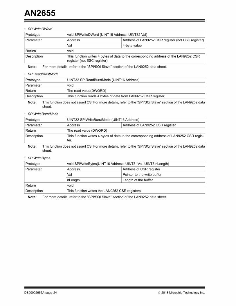
• SPIWriteDWord
Note: For more details, refer to the “SPI/SQI Slave” section of the LAN9252 data sheet.
• SPIReadBurstMode
Note: This function does not assert CS. For more details, refer to the “SPI/SQI Slave” section of the LAN9252 datasheet.
• SPIWriteBurstMode
Note: This function does not assert CS. For more details, refer to the “SPI/SQI Slave” section of the LAN9252 datasheet.
• SPIWriteBytes
Note: For more details, refer to the “SPI/SQI Slave” section of the LAN9252 data sheet.
Prototype void SPIWriteDWord (UINT16 Address, UINT32 Val)
Parameter Address Address of LAN9252 CSR register (not ESC register)
Val 4-byte value
Return void
Description This function writes 4 bytes of data to the corresponding address of the LAN9252 CSR register (not ESC register).
Prototype UINT32 SPIReadBurstMode (UINT16 Address)
Parameter void
Return The read value(DWORD)
Description This function reads 4 bytes of data from LAN9252 CSR register.
Prototype UINT32 SPIWriteBurstMode (UINT16 Address)
Parameter Address Address of LAN9252 CSR register
Return The read value (DWORD)
Description This function writes 4 bytes of data to the corresponding address of LAN9252 CSR regis-ter.
Prototype void SPIWriteBytes(UINT16 Address, UINT8 *Val, UINT8 nLength)
Parameter Address Address of CSR register
Val Pointer to the write buffer
nLength Length of the buffer
Return void
Description This function writes the LAN9252 CSR registers.
DS00002655A-page 24 2018 Microchip Technology Inc.

AN2655
5.3 Slave Controller Dependent APIs
The definition of the following APIs depends on the SSC controller used.
5.3.1 INTERRUPT API
5.3.1.1 PDI_Timer_Interrupt
5.3.1.2 PDI_IRQ_Interrupt
5.3.1.3 PDI_Enable_Global_interrupt
5.3.1.4 PDI_Disable_Global_Interrupt
Note: PDI_Restore_Global_Interrupt uses the previous state of the interrupt status to restore the interrupt status.
5.3.1.5 PDI_Init_SYNC_Interrupts
5.3.2 INTERRUPT HANDLERS
The following functions are provided by the generic SSC (defined in ecatappl.h) and must be called from the hardwareaccess layer.
5.3.2.1 ECAT_CheckTimer
Note: The timer ISR must be implemented as per the slave controller.
Prototype void PDI_Timer_Interrupt()
Parameter void
Return void
Description This function configures and enables the TIMER interrupt for 1 ms.
Prototype void PDI_IRQ_Interrupt()
Parameter void
Return void
Description This function configures and enables the interrupt for IRQ.
Prototype void PDI_Enable_Global_interrupt()
Parameter void
Return void
Description Enables interrupts in the slave controller.
Prototype UINT32 PDI_Disable_Global_Interrupt()
Parameter void
Return The previous state of the interrupt Status
Description This function reads the current interrupt status and disables all interrupt requests.
Prototype void PDI_Init_SYNC_Interrupts()
Parameter void
Return void
Description The function configures and enable SYNC0 and SYNC1 interrupts.
Prototype void ECAT_CheckTimer (void)
Parameter void
Return void
Description This function must be called every 1 ms from a timer ISR (ECAT_TIMER_INT = 1). If no timer interrupt is supported, this function is called automatically when 1 ms is elapsed (based on the provided timer).
2018 Microchip Technology Inc. DS00002655A-page 25

AN2655
5.3.2.2 PDI_Isr
Note: IRQ ISR must be implemented as per the slave controller.
5.3.2.3 Sync0_Isr
Note: SYNC0 ISR must be implemented as per the slave controller.
5.3.2.4 Sync1_Isr
Note: SYNC1 ISR must be implemented as per the slave controller.
5.3.3 HOST BUS INTERFACE
Host Bus Interface (HBI) can be in the Indexed or Multiplexed mode.
In Multiplexed Address or Data mode, the address and the endianness select inputs are shared with the data bus. Twomethods are supported: a single-phase address that utilizes up to 16 address or data pins and a dual-phase addressthat utilizes only the lower 8 data bits.
In Indexed Address mode, access to the internal registers and memory of the device are indirectly mapped using Indexand Data registers. The desired internal address is written into the device at a specific offset. The value written is thenused as the internal address when the associate Data register address is accessed. Three Index or Data register setsare provided allowing for multi-threaded operation without the concern of one thread corrupting the Index set by anotherthread.
For more details, refer to the “HBI Bus Interface” section of the LAN9252 data sheet.
5.3.3.1 PMPReadDWord
Note: This API must be implemented as per the slave controller if PDI interface is a host bus interface. This func-tion will call after initialization of the HBI of the slave controller.
Prototype void PDI_Isr (void)
Parameter void
Return void
Description This function must be called from the PDI ISR. For the PDI-specific pin naming and the interrupt generation logic, please refer to the LAN9252 data sheet. To support PDI inter-rupt handling, it is also required to set AL_EVENT_ENABLED to 1.
Prototype void Sync0_Isr (void)
Parameter void
Return void
Description This function must be called from the Sync0 ISR. The Sync0 interrupt is generated by the DC Unit of the ESC. It is currently not supported by default to map the Sync0 signal to the PDI interrupt. To support DC synchronization, DC_SUPPORTED must be set.
Prototype void Sync1_Isr (void)
Parameter void
Return void
Description This function must be called from the Sync1 ISR. The Sync1 interrupt is generated by the DC Unit of the ESC. It is currently not supported by default to map the Sync1 signal to the PDI interrupt. To support DC synchronization, DC_SUPPORTED must be set.
Prototype UINT32 PMPReadDWord (UINT16 Address)
Parameter Address Address of LAN9252 CSR register
Return The read value (DWORD)
Description This function reads 4 bytes of data from LAN9252 CSR register.
DS00002655A-page 26 2018 Microchip Technology Inc.

AN2655
5.3.3.2 PMPWriteDWord
Note: This API must be implemented as per the slave controller if PDI interface is a host bus interface. This func-tion will call after initialization of the HBI of the slave controller.
5.3.4 SPI
The SPI/SQI Slave module provides a low pin count synchronous slave interface that facilitates communication betweenthe device and a host system. The SPI/SQI Slave allows access to the System CSRs and internal FIFOs and memories.It supports single and multiple registers read and write commands with incrementing, decrementing, and static address-ing.
For more details, refer to the “SPI/SQI SLAVE” section of the LAN9252 data sheet.
5.3.4.1 SPIReadByte
5.3.4.2 SPIWriteByte
5.3.4.3 Macros
The following macros are related to the SOCs where SSC runs.
• CSLOW () – This macro drives the CS line low.
• CSHIGH () – This macro drives the CS line high.
• DISABLE_ESC_INT – Disables the IRQ interrupt
• ENABLE_ESC_INT – Enables the IRQ interrupt
• ECAT_TIMER_INC_P_MS – The timer ticks value (increments/ms)
Prototype void PMPWriteDWord (UINT16 Address, UINT32 Val)
Parameter Address Address of LAN9252 CSR register (not ESC register)
Val 4-byte value
Return void
Description This function writes 4 bytes of data to the corresponding address of LAN9252 CSR regis-ter (not ESC register).
Prototype void SPIReadByte ()
Parameter void
Return void
Description This function reads 1 byte of data from the LAN9252 CSR register. Refer to the LAN9252 data sheet on how to read using SPI.
Prototype void SPIWriteByte(UINT8 data)
Parameter data Data to write
Return void
Description This function writes 1 byte of data to the corresponding address of LAN9252 CSR regis-ter.
2018 Microchip Technology Inc. DS00002655A-page 27

AN2655
6.0 SSC TOOL CONFIGURATION FILE
The Microchip_LAN9252_SSC_Config.xml has the predefined macros that are required for generating the SSC codeabout LAN9252 ESC. The default values available in this config file can be updated using the SSC tool or modifying thesame file itself.
Note: For more information about the SSC tool, refer to EtherCAT Slave Stack Code (SSC) ET9300 web page(www.ethercat.org).
DS00002655A-page 28 2018 Microchip Technology Inc.

2018 Microchip Technology Inc. DS00002655A-page 29
AN2655
APPENDIX A: REVISION HISTORY
TABLE A-1: REVISION HISTORY
Revision Section/Figure/Entry Correction
DS00002655A (02-23-18)
Initial release

AN2655
DS00002655A-page 30 2018 Microchip Technology Inc.
THE MICROCHIP WEB SITE
Microchip provides online support via our WWW site at www.microchip.com. This web site is used as a means to makefiles and information easily available to customers. Accessible by using your favorite Internet browser, the web sitecontains the following information:
• Product Support – Data sheets and errata, application notes and sample programs, design resources, user’s guides and hardware support documents, latest software releases and archived software
• General Technical Support – Frequently Asked Questions (FAQ), technical support requests, online discussion groups, Microchip consultant program member listing
• Business of Microchip – Product selector and ordering guides, latest Microchip press releases, listing of seminars and events, listings of Microchip sales offices, distributors and factory representatives
CUSTOMER CHANGE NOTIFICATION SERVICE
Microchip’s customer notification service helps keep customers current on Microchip products. Subscribers will receivee-mail notification whenever there are changes, updates, revisions or errata related to a specified product family ordevelopment tool of interest.
To register, access the Microchip web site at www.microchip.com. Under “Support”, click on “Customer Change Notifi-cation” and follow the registration instructions.
CUSTOMER SUPPORT
Users of Microchip products can receive assistance through several channels:
• Distributor or Representative
• Local Sales Office
• Field Application Engineer (FAE)
• Technical Support
Customers should contact their distributor, representative or Field Application Engineer (FAE) for support. Local salesoffices are also available to help customers. A listing of sales offices and locations is included in the back of thisdocument.
Technical support is available through the web site at: http://microchip.com/support

2018 Microchip Technology Inc. DS00002655A-page 31
Information contained in this publication regarding device applications and the like is provided only for your convenience and may besuperseded by updates. It is your responsibility to ensure that your application meets with your specifications. MICROCHIP MAKES NOREPRESENTATIONS OR WARRANTIES OF ANY KIND WHETHER EXPRESS OR IMPLIED, WRITTEN OR ORAL, STATUTORY OROTHERWISE, RELATED TO THE INFORMATION, INCLUDING BUT NOT LIMITED TO ITS CONDITION, QUALITY, PERFOR-MANCE, MERCHANTABILITY OR FITNESS FOR PURPOSE. Microchip disclaims all liability arising from this information and its use.Use of Microchip devices in life support and/or safety applications is entirely at the buyer’s risk, and the buyer agrees to defend, indemnifyand hold harmless Microchip from any and all damages, claims, suits, or expenses resulting from such use. No licenses are conveyed,implicitly or otherwise, under any Microchip intellectual property rights unless otherwise stated.
Trademarks
The Microchip name and logo, the Microchip logo, AnyRate, AVR, AVR logo, AVR Freaks, BeaconThings, BitCloud, CryptoMemory, CryptoRF, dsPIC, FlashFlex, flexPWR, Heldo, JukeBlox, KEELOQ, KEELOQ logo, Kleer, LANCheck, LINK MD, maXStylus, maXTouch, MediaLB, megaAVR, MOST, MOST logo, MPLAB, OptoLyzer, PIC, picoPower, PICSTART, PIC32 logo, Prochip Designer, QTouch, RightTouch, SAM-BA, SpyNIC, SST, SST Logo, SuperFlash, tinyAVR, UNI/O, and XMEGA are registered trademarks of Microchip Technology Incorporated in the U.S.A. and other countries.
ClockWorks, The Embedded Control Solutions Company, EtherSynch, Hyper Speed Control, HyperLight Load, IntelliMOS, mTouch, Precision Edge, and Quiet-Wire are registered trademarks of Microchip Technology Incorporated in the U.S.A.
Adjacent Key Suppression, AKS, Analog-for-the-Digital Age, Any Capacitor, AnyIn, AnyOut, BodyCom, chipKIT, chipKIT logo, CodeGuard, CryptoAuthentication, CryptoCompanion, CryptoController, dsPICDEM, dsPICDEM.net, Dynamic Average Matching, DAM, ECAN, EtherGREEN, In-Circuit Serial Programming, ICSP, Inter-Chip Connectivity, JitterBlocker, KleerNet, KleerNet logo, Mindi, MiWi, motorBench, MPASM, MPF, MPLAB Certified logo, MPLIB, MPLINK, MultiTRAK, NetDetach, Omniscient Code Generation, PICDEM, PICDEM.net, PICkit, PICtail, PureSilicon, QMatrix, RightTouch logo, REAL ICE, Ripple Blocker, SAM-ICE, Serial Quad I/O, SMART-I.S., SQI, SuperSwitcher, SuperSwitcher II, Total Endurance, TSHARC, USBCheck, VariSense, ViewSpan, WiperLock, Wireless DNA, and ZENA are trademarks of Microchip Technology Incorporated in the U.S.A. and other countries.
SQTP is a service mark of Microchip Technology Incorporated in the U.S.A.
Silicon Storage Technology is a registered trademark of Microchip Technology Inc. in other countries.
GestIC is a registered trademark of Microchip Technology Germany II GmbH & Co. KG, a subsidiary of Microchip Technology Inc., in other countries.
All other trademarks mentioned herein are property of their respective companies.
© 2018, Microchip Technology Incorporated, All Rights Reserved.
ISBN: 978-1-5224-2711-7
Note the following details of the code protection feature on Microchip devices:
• Microchip products meet the specification contained in their particular Microchip Data Sheet.
• Microchip believes that its family of products is one of the most secure families of its kind on the market today, when used in the intended manner and under normal conditions.
• There are dishonest and possibly illegal methods used to breach the code protection feature. All of these methods, to our knowledge, require using the Microchip products in a manner outside the operating specifications contained in Microchip’s Data Sheets. Most likely, the person doing so is engaged in theft of intellectual property.
• Microchip is willing to work with the customer who is concerned about the integrity of their code.
• Neither Microchip nor any other semiconductor manufacturer can guarantee the security of their code. Code protection does not mean that we are guaranteeing the product as “unbreakable.”
Code protection is constantly evolving. We at Microchip are committed to continuously improving the code protection features of ourproducts. Attempts to break Microchip’s code protection feature may be a violation of the Digital Millennium Copyright Act. If such actsallow unauthorized access to your software or other copyrighted work, you may have a right to sue for relief under that Act.
Microchip received ISO/TS-16949:2009 certification for its worldwide headquarters, design and wafer fabrication facilities in Chandler and Tempe, Arizona; Gresham, Oregon and design centers in California and India. The Company’s quality system processes and procedures are for its PIC® MCUs and dsPIC® DSCs, KEELOQ® code hopping devices, Serial EEPROMs, microperipherals, nonvolatile memory and analog products. In addition, Microchip’s quality system for the design and manufacture of development systems is ISO 9001:2000 certified.
QUALITYMANAGEMENTSYSTEMCERTIFIEDBYDNV
== ISO/TS16949==

DS00002655A-page 32 2018 Microchip Technology Inc.
AMERICASCorporate Office2355 West Chandler Blvd.Chandler, AZ 85224-6199Tel: 480-792-7200 Fax: 480-792-7277Technical Support: http://www.microchip.com/supportWeb Address: www.microchip.com
AtlantaDuluth, GA Tel: 678-957-9614 Fax: 678-957-1455
Austin, TXTel: 512-257-3370
BostonWestborough, MA Tel: 774-760-0087 Fax: 774-760-0088
ChicagoItasca, IL Tel: 630-285-0071 Fax: 630-285-0075
DallasAddison, TX Tel: 972-818-7423 Fax: 972-818-2924
DetroitNovi, MI Tel: 248-848-4000
Houston, TX Tel: 281-894-5983
IndianapolisNoblesville, IN Tel: 317-773-8323Fax: 317-773-5453Tel: 317-536-2380
Los AngelesMission Viejo, CA Tel: 949-462-9523Fax: 949-462-9608Tel: 951-273-7800
Raleigh, NC Tel: 919-844-7510
New York, NY Tel: 631-435-6000
San Jose, CA Tel: 408-735-9110Tel: 408-436-4270
Canada - TorontoTel: 905-695-1980 Fax: 905-695-2078
ASIA/PACIFICAustralia - SydneyTel: 61-2-9868-6733
China - BeijingTel: 86-10-8569-7000
China - ChengduTel: 86-28-8665-5511
China - ChongqingTel: 86-23-8980-9588
China - DongguanTel: 86-769-8702-9880
China - GuangzhouTel: 86-20-8755-8029
China - HangzhouTel: 86-571-8792-8115
China - Hong Kong SARTel: 852-2943-5100
China - NanjingTel: 86-25-8473-2460
China - QingdaoTel: 86-532-8502-7355
China - ShanghaiTel: 86-21-3326-8000
China - ShenyangTel: 86-24-2334-2829
China - ShenzhenTel: 86-755-8864-2200
China - SuzhouTel: 86-186-6233-1526
China - WuhanTel: 86-27-5980-5300
China - XianTel: 86-29-8833-7252
China - XiamenTel: 86-592-2388138
China - ZhuhaiTel: 86-756-3210040
ASIA/PACIFICIndia - BangaloreTel: 91-80-3090-4444
India - New DelhiTel: 91-11-4160-8631
India - PuneTel: 91-20-4121-0141
Japan - OsakaTel: 81-6-6152-7160
Japan - TokyoTel: 81-3-6880- 3770
Korea - DaeguTel: 82-53-744-4301
Korea - SeoulTel: 82-2-554-7200
Malaysia - Kuala LumpurTel: 60-3-7651-7906
Malaysia - PenangTel: 60-4-227-8870
Philippines - ManilaTel: 63-2-634-9065
SingaporeTel: 65-6334-8870
Taiwan - Hsin ChuTel: 886-3-577-8366
Taiwan - KaohsiungTel: 886-7-213-7830
Taiwan - TaipeiTel: 886-2-2508-8600
Thailand - BangkokTel: 66-2-694-1351
Vietnam - Ho Chi MinhTel: 84-28-5448-2100
EUROPEAustria - WelsTel: 43-7242-2244-39Fax: 43-7242-2244-393
Denmark - CopenhagenTel: 45-4450-2828 Fax: 45-4485-2829
Finland - EspooTel: 358-9-4520-820
France - ParisTel: 33-1-69-53-63-20 Fax: 33-1-69-30-90-79
Germany - GarchingTel: 49-8931-9700
Germany - HaanTel: 49-2129-3766400
Germany - HeilbronnTel: 49-7131-67-3636
Germany - KarlsruheTel: 49-721-625370
Germany - MunichTel: 49-89-627-144-0 Fax: 49-89-627-144-44
Germany - RosenheimTel: 49-8031-354-560
Israel - Ra’anana Tel: 972-9-744-7705
Italy - Milan Tel: 39-0331-742611 Fax: 39-0331-466781
Italy - PadovaTel: 39-049-7625286
Netherlands - DrunenTel: 31-416-690399 Fax: 31-416-690340
Norway - TrondheimTel: 47-7289-7561
Poland - WarsawTel: 48-22-3325737
Romania - BucharestTel: 40-21-407-87-50
Spain - MadridTel: 34-91-708-08-90Fax: 34-91-708-08-91
Sweden - GothenbergTel: 46-31-704-60-40
Sweden - StockholmTel: 46-8-5090-4654
UK - WokinghamTel: 44-118-921-5800Fax: 44-118-921-5820
Worldwide Sales and Service
10/25/17