AN Wireless Tower Assembly · PDF fileAN Wireless Tower Assembly Instructions ... purchase of...
37
AN Wireless Tower Assembly Instructions READ THOROUGHLY BEFORE ASSEMBLY AND ERECTION Thank you for your purchase of an AN Wireless Self Supporting Tower. AN Wireless Towers are designed and fabricated to be high-strength, high-quality and well designed pieces of infrastructure equipment, intended to offer many decades of service life. AN Wireless Towers are designed and produced in accordance with National Standard ANSI/TIA- 222-G. Handling, rigging and erecting towers of this type must be assigned to qualified and experienced personnel. It is the full responsibility of the customer / erector to properly assemble and erect AN Wireless Towers. All models of AN Wireless Towers utilize a different stacking configuration with the twelve (12) available tapered sections to achieve the required height (120 ft. maximum). Tower sections are numbered from 1 thru 12, with section 1 being the widest section available, and section 12 being the narrowest section available. Allowable Design Loading & Foundation Plans Refer to our website to download the Allowable Design Loading and required Foundation Drawings for a specific tower at the following URL: www.anwireless.com/tower.html If you are unsure how to interpret these tables, drawings or information, or if you require further site-specific design data, contact us for assistance. Fastener Torque AISC does not provide torque specifications as a means to indicate bolt preload. The reason is because the relationship varies greatly depending on bolt length, thread roughness, bolt coating and lubricity. The below estimated torque calculations are only offered as a guide. Due to many variables that affect the torque-tension relationship such as human error, surface texture and lubrication, the only way to determine the correct torque is through experimentation under actual joint and assembly conditions. The recommended torque values are based on factory condition. AN Wireless Tower bolts are used in shear, so the concern is that the bolts to not loosen over time. A periodic inspection of all bolted connections is recommended. Tightening torque – suggested starting values: 3/8” x 1 Brace Bolt, 16 TPI – 16 ft. lbs. 1/2" x 1-1/2” Leg Bolt, 13 TPI – 75-94 ft. lbs.
Transcript of AN Wireless Tower Assembly · PDF fileAN Wireless Tower Assembly Instructions ... purchase of...

AN Wireless Tower Assembly Instructions
READ THOROUGHLY BEFORE ASSEMBLY AND ERECTION Thank you for your purchase of an AN Wireless Self Supporting Tower. AN Wireless Towers are designed and fabricated to be high-strength, high-quality and well designed pieces of infrastructure equipment, intended to offer many decades of service life. AN Wireless Towers are designed and produced in accordance with National Standard ANSI/TIA-222-G. Handling, rigging and erecting towers of this type must be assigned to qualified and experienced personnel. It is the full responsibility of the customer / erector to properly assemble and erect AN Wireless Towers. All models of AN Wireless Towers utilize a different stacking configuration with the twelve (12) available tapered sections to achieve the required height (120 ft. maximum). Tower sections are numbered from 1 thru 12, with section 1 being the widest section available, and section 12 being the narrowest section available.
Allowable Design Loading & Foundation Plans Refer to our website to download the Allowable Design Loading and required Foundation Drawings for a specific tower at the following URL: www.anwireless.com/tower.html If you are unsure how to interpret these tables, drawings or information, or if you require further site-specific design data, contact us for assistance.
Fastener Torque
AISC does not provide torque specifications as a means to indicate bolt preload. The reason is because the relationship varies greatly depending on bolt length, thread roughness, bolt coating and lubricity. The below estimated torque calculations are only offered as a guide. Due to many variables that affect the torque-tension relationship such as human error, surface texture and lubrication, the only way to determine the correct torque is through experimentation under actual joint and assembly conditions. The recommended torque values are based on factory condition. AN Wireless Tower bolts are used in shear, so the concern is that the bolts to not loosen over time. A periodic inspection of all bolted connections is recommended. Tightening torque – suggested starting values: 3/8” x 1 Brace Bolt, 16 TPI – 16 ft. lbs. 1/2" x 1-1/2” Leg Bolt, 13 TPI – 75-94 ft. lbs.

5’ Concrete Base Section Assembly 1) Identify the Upper Braces (shortest length), Lower Braces (middle length) and Diagonal braces
(longest length). Three (3) of each length are included, and all braces are 1/8” x 1-1/2” angle.
2) Locate the brace mounting holes as marked on the 5’ long Concrete Base Section legs.
3) Bolt the Upper Braces (3) and Lower braces (3) in place with the supplied 1/2" fasteners. These (6) braces mount to the OUTSIDE of the 5’ Base Section legs. Keep the fasteners loose for now.
4) Bolt the Diagonal Braces (3) in place with the supplied 1/2" fasteners. These (3) braces mount to the INSIDE of the 5’ Concrete Base Section legs, and share the same 1/2” fasteners used for the Upper Braces and Lower Braces. Keep all fasteners loose for now.
5) Ensure the UPPER Concrete Base Section leg face width of each of the (3) 5’ Concrete Base Section legs is within + or - 1/16” of the bottom face width of the tower section that will mount directly above the 5’ Concrete Base Section. These measurements must be taken from the outside leg apex to outside leg apex on all (3) section faces on both adjoining sections. The LOWER Concrete Base Section leg face width is not critical.
6) Fully tighten all fasteners.
7) With the Concrete Base Section placed in the foundation hole, plumb each 5’ Concrete Base Section leg for equal vertical straightness, taking into consideration the taper of the Concrete Base Section legs. Adjust as necessary. Provide temporary guying or support if necessary.
8) Pour concrete down through the middle of the Concrete Base Section to ensure minimal disturbance of the Concrete Base Section or rebar.
9) The final concrete level must be 9” from the top of each of the 5’ Concrete Base Section legs. In other words, 9” of the Concrete Base Section legs must remain exposed above concrete.
IF LOCATION OF UNDERGROUND UTILITIES IS UNKNOWN, CALL BEFORE YOU DIG!
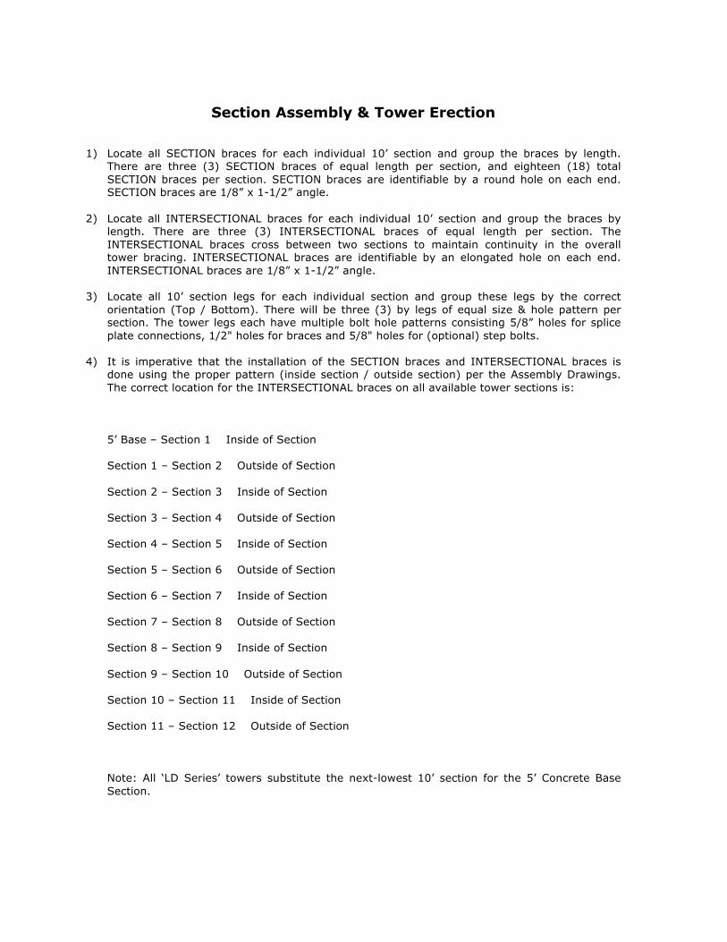
Section Assembly & Tower Erection 1) Locate all SECTION braces for each individual 10’ section and group the braces by length.
There are three (3) SECTION braces of equal length per section, and eighteen (18) total SECTION braces per section. SECTION braces are identifiable by a round hole on each end. SECTION braces are 1/8” x 1-1/2” angle.
2) Locate all INTERSECTIONAL braces for each individual 10’ section and group the braces by length. There are three (3) INTERSECTIONAL braces of equal length per section. The INTERSECTIONAL braces cross between two sections to maintain continuity in the overall tower bracing. INTERSECTIONAL braces are identifiable by an elongated hole on each end. INTERSECTIONAL braces are 1/8” x 1-1/2” angle.
3) Locate all 10’ section legs for each individual section and group these legs by the correct orientation (Top / Bottom). There will be three (3) by legs of equal size & hole pattern per section. The tower legs each have multiple bolt hole patterns consisting 5/8” holes for splice plate connections, 1/2" holes for braces and 5/8" holes for (optional) step bolts.
4) It is imperative that the installation of the SECTION braces and INTERSECTIONAL braces is done using the proper pattern (inside section / outside section) per the Assembly Drawings. The correct location for the INTERSECTIONAL braces on all available tower sections is: 5’ Base – Section 1 Inside of Section Section 1 – Section 2 Outside of Section Section 2 – Section 3 Inside of Section Section 3 – Section 4 Outside of Section Section 4 – Section 5 Inside of Section Section 5 – Section 6 Outside of Section Section 6 – Section 7 Inside of Section Section 7 – Section 8 Outside of Section Section 8 – Section 9 Inside of Section Section 9 – Section 10 Outside of Section Section 10 – Section 11 Inside of Section Section 11 – Section 12 Outside of Section Note: All ‘LD Series’ towers substitute the next-lowest 10’ section for the 5’ Concrete Base Section.

5) Begin installing SECTION braces using the supplied 3/8” bolts, nuts and lock washers. Braces are installed with two braces sharing one bolt used in single-shear. A round file may be useful to clean out holes from excess zinc, though this is a rare occurrence. Keep all bolt heads on the outside of the section, and threads on the inside. Use the Assembly Drawings as a guide for correct SECTION brace location and inside / outside orientation. Sections, as well as the entire tower, must be assembled on a level surface to ensure proper section alignment, and to avoid building a bow or arch into the length of the tower. The flat, notched side of the SECTION braces must face up towards the top of the tower. Keep all connections finger-tight.
6) Once the SECTION braces have been installed on all (3) faces of the entire tower, begin installing the INTERSECTIONAL braces using the supplied 3/8” bolts, nuts and lock washers. A round file may be useful to clean out holes from excess zinc, though this is a rare occurrence. Keep all bolt heads on the outside of the section, and threads on the inside. Use the Assembly Drawings as a guide for correct INTERSECTIONAL brace location and inside / outside orientation. The INTERSECTIONAL braces share the same fasteners used for the SECTION braces. The flat, notched side of the INTERSECTIONAL braces must face up towards the top of the tower. Keep all connections finger-tight.
7) Use the Assembly Drawings as a guide to achieve the correct section face measurements for the top and bottom of each section. These measurements must be taken from the outside leg apex to outside leg apex on all (3) section faces on the top and bottom of all sections. After all SECTION and INTERSECTIONAL bracing has been installed and the top & bottom of each section is checked for the correct face width matching the Assembly Drawings, tighten only the 3/8” SECTION brace bolts, section by section, leaving the INTERSECTIONAL brace bolts finger-tight.
8) Join the 10’ sections using the supplied hardware. Twelve (12) Splice Plates are used at each section joint (4 per leg), with twenty-four (24) 1/2” x 1-1/2” bolts, nuts and lock washers (8 per leg). Two different widths of Splice Plates are used in our complete 120 ft. tower design. Refer to the Assembly Drawings for correct Splice Plate width and location based on the tower sections used. The Splice Plates mount on both the inside and outside of each tower leg. The 2” wide Splice Plates must be used between the following sections: 5’ Base – Section 1 Section 1 (or 5’ Base) – Section 2 Section 2 (or 5’ Base) – Section 3 Section 3 (or 5’ Base) – Section 4 The 1-3/4” wide Splice Plates must be used between the following sections: Section 4 (or 5’ Base) – Section 5 Section 5 (or 5’ Base) – Section 6 Section 6 (or 5’ Base) – Section 7 Section 7 (or 5’ Base) – Section 8 Section 8 (or 5’ Base) – Section 9 Section 9 (or 5’ Base) – Section 10 Section 10 (or 5’ Base) – Section 11 Section 11 (or 5’ Base) – Section 12

9) Maintain consistent gap between each of the three (3) legs in each section joint. Shim sections as necessary.
10) After it has been determined the sections are all straight and the assembled tower is plumb, tighten all of the 3/8” INTERSECTIONAL fasteners and all of the 1/2” leg / Splice Plate fasteners.
11) When installing the tower with a crane, avoid using the very top of the tower as a lift point. Assuming an empty tower, generally a good lift point is 2/3 of the way up the tower.

Optional Tower Accessories
Step Bolts This option includes 1/2” diameter stainless steel Step Bolts for the purpose of ascending and descending the tower more safely. The 1/2” Step Bolts are installed in the 5/8" holes provided in each tower leg (6 per leg) on alternating sides of the leg. Another Step Bolt is installed in one of the Splice Plate holes. Select the correct Splice Plate hole to continue the alternating left / right pattern of the Step Bolts. All Step Bolts use two (2) nuts and (2) lock washers. Fixed-Mount Mast Plates / Rotator Plates / Thrust Bearing Plates This option includes the selected triangular mounting plate with three (3) welded plate mounts. The (3) plate mounts are each bolted into the inside apex of the appropriate tower leg to provide a solid mount for the mounting plate. The mounting plate then bolts to the top of all (3) plate mounts using the supplied 1/2” bolts, nuts and lock washers. This plate mounting design offers a maximum open surface area available for use on the plate surface, while allowing the plate to easily enter the section from the outside. In the case of Rotator and Thrust Bearing plates, a small locating hole is provided in the center of each plate. Anti-Climb Panels This option includes three (3) sheets of pre-sheared expanded metal and three (3) expanded metal corner covers. The expanded sheet is sheared to match the taper of the bottom tower section and cover it on all sides to restrict climbing. Once the three (3) expanded panels are placed against the tower section, the three (3) corner covers may then be installed on the outside at each corner and secured in place using the supplied 1/2" bolts, nuts and lockwashers. Eight (8) fasteners per corner are used to secure the assembly. Wear gloves to protect against sharp edges. Rock / Rooftop Mounts This option includes a set of three (3) mounts that replace our 5’ Concrete Base Section. Because this is a very custom and site-specific option, no rock anchors or other base-mounting hardware is included as standard. Use the supplied 1/2" bolts, nuts, lock washers and splice plates to fasten the Rock / Rooftop Mounts to the tower legs. Tower Grounding Kit This option includes a set of three (3) 5/8” ground rods, solid copper wire, lugs, clamps and hardware for connection to each of the tower legs. Use the stainless steel hardware provided to attach the copper ground lugs to the tower legs at the lowest INTERSECTIONAL brace hole position.

TO
WE
R E
LE
VA
TIO
N
TO
WE
R D
ES
IG
N L
OA
DIN
G
AN
TE
NN
A T
YP
ELIN
E T
YP
E
(3) 1/2"Ø coax
HE
IG
HT
(F
T.)
NO
TE
S
1.
2.
PE
R A
NS
I/T
IA
-222-G
-2-2009, A
SC
E/S
EI 7-05 A
ND
T
HE
2009 IN
TE
RN
AT
IO
NA
L B
UILD
IN
G C
OD
E.
90-M
PH
3-S
EC
ON
D G
US
T (E
XP
OS
UR
E B
, S
TR
UC
TU
RE
C
LA
SS
I, T
OP
OG
RA
PH
IC
C
AT
EG
OR
Y 1)
CaA
a =
15 sq. ft.
NO
.S
HE
ET
T
IT
LE
RE
VIS
IO
ND
AT
E
HD
-120-K
A12-02-15
AN
W-S
1
AN
W-S
2
AN
W-S
3
AN
W-S
4
AN
W-S
5
AN
W-S
6
SE
CT
IO
N 3 A
SS
EM
BLY
SE
CT
IO
N 4 A
SS
EM
BLY
SE
CT
IO
N 5 A
SS
EM
BLY
HD
-1
20
R
EQ
UIR
ED
D
RA
WIN
GS
SE
CT
IO
N 6 A
SS
EM
BLY
SE
CT
IO
N 7 A
SS
EM
BLY
SE
CT
IO
N 8 A
SS
EM
BLY
SE
CT
IO
N 9 A
SS
EM
BLY
AN
W-S
7
FO
R C
LIM
BIN
G F
AC
ILIT
IE
S R
EF
ER
T
O A
N WIRELE
SS
.
FO
R A
PP
UR
TE
NA
NC
E IN
ST
ALLA
TIO
N R
EF
ER
T
O A
N WIRELE
SS
.
120
AN
W-S
8
AN
W-S
9
AN
W-S
10
AN
W-S
11
AN
W-S
12
SE
CT
IO
N 2 A
SS
EM
BLY
SE
CT
IO
N 1 A
SS
EM
BLY
SE
CT
IO
N 10 A
SS
EM
BLY
SE
CT
IO
N 11 A
SS
EM
BLY
SE
CT
IO
N 12 A
SS
EM
BLY
0'-0" (R
EF
)
T/T
OW
ER
B/S
EC
TIO
N 1
120'-0"
SECTION 3SECTION 4SECTION 5SECTION 6SECTION 7SECTION 8SECTION 9SECTION 10SECTION 11SECTION 12 SECTION 2 SECTION 1
HD
120 A
SS
EM
BLY
K
EY
1 1 1 1 1 1 1 1 1 1 1 1 1
12-02-15
12-02-15
12-02-15
12-02-15
12-02-15
12-02-15
12-02-15
12-02-15
12-02-15
12-02-15
12-02-15
12-02-15
(X COUNTY)
TBD, TBD XXXXX
HD120 ASSEMBLY KEY
HD-120-KA
TBD

SECTION 1 ELEVATION
QTY. DESCRIPTION
MATERIAL LIST
PIECE MARK
3
3
3
3
3
3
3
SECTION A-A
SECTION C-C
SCALE: N.T.S.
SECTION LEG (TYP)
SEE MATERIAL LIST,
THIS SHEET.
SECTION 1
LEG
BASE
SECTION
B B
A A
SECTION B-B
SCALE: N.T.S.
CC
BRACE BOLT
LEG BOLT
SPLICE PLATE
21
24
12
LEG BOLT ASSEMBLY.
(TYP) SEE MATERIAL
LIST THIS SHEET
3/8" Ø x 1" BOLT ASSEMBLY
1/2" Ø x 1 1/2" BOLT ASSEMBLY
NOTES
DIAGONAL BRACE BOLT
ASSEMBLY.(TYP) SEE
MATERIAL LIST THIS
SHEET.
1/8 " GAP
SCALE: N.T.S.
DIAGONAL D-BRACING
SEE MATERIAL LIST,
THIS SHEET.
SPLICE PLATE
SEE MATERIAL LIST
THIS SHEET. (TYP)
10'-0"
FOR SECTION LOCATION AND ORIENTATION SEE
ASSEMBLY KEY.
LOCKWASHERS TO BE INSTALLED AT ALL BOLTED
CONNECTIONS.
APPROXIMATE THEORETICAL SECTION WEIGHT BEFORE
GALVANIZING = 311#
BEND RADIUS FOR LEG = 1/2 "
STEEL GRADES
:BRACES
:LEG BOLTS
:BRACE BOLTS
ALL MATERIALS SHALL BE HOT-DIP GALVANIZED
PER ASTM A123 AND A153
1.
2.
4.
5.
6.
7.
4'-3 19/32 "
KK
3A
N-L1
P 7" x 1/4" x 10'-0"
P 2" x 3/16" x 0'- 7 3/8"
3 L 1-1/2 " x 1-1/2" x 1/8" x 49-13/16"
KK3AN-L1
KK3AN-D1A
KK3AN-D1B
KK3AN-D1C
KK3AN-D1D
KK3AN-D1E
KK3AN-D1F
KK3AN-D1H
4'-7 3/16 "
K
K
3
A
N
-
D
1
A
K
K
3
A
N
-
D
1
B
K
K
3
A
N
-
D
1
C
K
K
3
A
N
-
D
1
D
K
K
3
A
N
-
D
1
E
KK3AN-D1H
K
K
3
A
N
-
D
1
F
KK
3A
N-L1
HORIZONTAL BRACE
NEEDED IF SECTION 1
IS THE TOP OF TOWER
K
K
3
A
N
-D
1
G
L
L
:LEGS ASTM A572 GR. 50
ASTM A36
ASTM A325, TYPE X
SAE GRADE 5
L 1-1/2" x 1-1/2" x 1/8" x 55-13/16"
L 1-1/2" x 1-1/2" x 1/8" x 55-5/16"
L 1-1/2" x 1-1/2" x 1/8" x 54-13/16"
L 1-1/2" x 1-1/2" x 1/8" x 54-5/16"
L 1-1/2" x 1-1/2" x 1/8" x 53-13/16"
L 1-1/2" x 1-1/2" x 1/8" x 53-5/16"
:SPLICE PLATES ASTM A36
DESIGN AND FABRICATION IN ACCORDANCE WITH THE
ANSI/AISC 360-05 STANDARD.
3.
3KK3AN-D1G L 1-1/2" x 1-1/2" x 1/8" x 54-3/4"
64893_40585
SEAL:
REGLSB
SHEET TITLE :
SHEET NUMBER : REVISION:
JOB NO.: CHECKED BY:DRAWN BY:
CONSTRUCTION (TEP# 110001.04)0 02-01-05
1
REVISED PER CLIENT1 12-02-15
December 2, 2015
TOWER MANUFACTURER : TOWER DESIGNER :
326 Tryon Road
Raleigh, NC 27603
Office: (919) 661-6351
Fax: (919) 661-6350
350 Kuhn Fording Road
East Berlin, PA 17316
Office: (717) 259-0419
www.tepgroup.netwww.anwtowers.com
Mobile: (717) 465-0519
SECTION 1 ASSEMBLY
ANW-S1
SECTION 2 ELEVATION
QTY.DESCRIPTION
MATERIAL LIST
PIECE MARK
3
3
3
3
3
3
3
KK3AN-L2
KK3AN-D2A
KK3AN-D2B
KK3AN-D2C
KK3AN-D2D
KK3AN-D2E
KK3AN-D2F
SECTION LEG (TYP)
SEE MATERIAL LIST,
THIS SHEET.
B B
A A
BRACE BOLT
LEG BOLT
SPLICE PLATE
21
24
12
3/8" Ø x 1" BOLT ASSEMBLY
1/2" Ø x 1 1/2" BOLT ASSEMBLY
DIAGONAL D-BRACING
SEE MATERIAL LIST,
THIS SHEET.
10'-0"
4'-0"
KK
3A
N-L2
KK
3A
N-L2
P 6 1/4" x 1/4" x 10'-0"
P 2" x 3/16" x 0'- 7 3/8"
KK3AN-D2H
3KK3AN-D2H
HORIZONTAL BRACE
NEEDED IF SECTION 2
IS THE TOP OF TOWER
4'-3 19/32 "
K
K
3
A
N
-
D
2
A
K
K
3
A
N
-
D
2
B
K
K
3
A
N
-
D
2
C
K
K
3
A
N
-
D
2
D
K
K
3
A
N
-
D
2
E
K
K
3
A
N
-
D
2
F
L 1-1/2" x 1-1/2" x 1/8" x 46-3/16"
THIS SHEET. (TYP)
SEE MATERIAL LIST
SPLICE PLATE
SCALE: N.T.S.
SHEET.
MATERIAL LIST THIS
ASSEMBLY.(TYP) SEE
DIAGONAL BRACE BOLT
LIST THIS SHEET
(TYP) SEE MATERIAL
LEG BOLT ASSEMBLY.
C C
SCALE: N.T.S.
SECTION B-B
SCALE: N.T.S.
SECTION C-C
SECTION A-A
L
L
L 1-1/2" x 1-1/2" x 1/8" x 49-15/16"
L 1-1/2" x 1-1/2" x 1/8" x 50-7/16"
L 1-1/2" x 1-1/2" x 1/8" x 50-15/16"
L 1-1/2" x 1-1/2" x 1/8" x 51-7/16"
L 1-1/2" x 1-1/2" x 1/8" x 51-15/16"
L 1-1/2" x 1-1/2" x 1/8" x 52-7/16"
1/8 " GAP
LEG
SECTION 1
LEG
SECTION 2
K
K
3
A
N
-D
2
G
3KK3AN-D2G L 1-1/2" x 1-1/2" x 1/8" x 51-1/4"
NOTES
FOR SECTION LOCATION AND ORIENTATION SEE
ASSEMBLY KEY.
LOCKWASHERS TO BE INSTALLED AT ALL BOLTED
CONNECTIONS.
APPROXIMATE THEORETICAL SECTION WEIGHT BEFORE
GALVANIZING = 284#
BEND RADIUS FOR LEG = 1/2 "
STEEL GRADES
:BRACES
:LEG BOLTS
:BRACE BOLTS
ALL MATERIALS SHALL BE HOT-DIP GALVANIZED
PER ASTM A123 AND A153
1.
2.
4.
5.
6.
7.
:LEGS ASTM A572 GR. 50
ASTM A36
:SPLICE PLATES ASTM A36
DESIGN AND FABRICATION IN ACCORDANCE WITH THE
ANSI/AISC 360-05 STANDARD.
3.
ASTM A325, TYPE X
SAE GRADE 5
64893_40585
SEAL:
REGLSB
SHEET TITLE :
SHEET NUMBER : REVISION:
JOB NO.: CHECKED BY:DRAWN BY:
CONSTRUCTION (TEP# 110001.04)0 02-01-05
1
REVISED PER CLIENT1 12-02-15
December 2, 2015
TOWER MANUFACTURER : TOWER DESIGNER :
326 Tryon Road
Raleigh, NC 27603
Office: (919) 661-6351
Fax: (919) 661-6350
350 Kuhn Fording Road
East Berlin, PA 17316
Office: (717) 259-0419
www.tepgroup.netwww.anwtowers.com
Mobile: (717) 465-0519
SECTION 2 ASSEMBLY
ANW-S2

SECTION 3 ELEVATION
QTY.DESCRIPTION
MATERIAL LIST
PIECE MARK
3
3
3
3
3
3
3
KK3AN-L3
KK3AN-D3A
KK3AN-D3B
KK3AN-D3C
KK3AN-D3D
KK3AN-D3E
KK3AN-D3F
SECTION LEG (TYP)
SEE MATERIAL LIST,
THIS SHEET.
B B
A A
3KK3AN-D3G
BRACE BOLT
LEG BOLT
SPLICE PLATE
21
24
12
3/8" Ø x 1" BOLT ASSEMBLY
1/2" Ø x 1 1/2" BOLT ASSEMBLY
DIAGONAL D-BRACING
SEE MATERIAL LIST,
THIS SHEET.
10'-0"
K
K
3
A
N
-
D
3
A
K
K
3
A
N
-
D
3
B
K
K
3
A
N
-
D
3
C
K
K
3
A
N
-
D
3
D
K
K
3
A
N
-
D
3
E
K
K
3
A
N
-
D
3
F
KK
3A
N-L3
KK
3A
N-L3
L 1-1/2" x 1-1/2" x 1/8" x 47-7/8"
P 5-1/2" x 1/4" x 10'-0"
P 2" x 3/16" x 0'- 7 3/8"
KK3AN-D3H
3KK3AN-D3H L 1-1/2" x 1-1/2" x 1/8" x 42-9/16"
HORIZONTAL BRACE
NEEDED IF SECTION 3
IS THE TOP OF TOWER
SECTION A-A
SECTION C-C
SCALE: N.T.S.
SECTION B-B
SCALE: N.T.S.
CC
LEG BOLT ASSEMBLY.
(TYP) SEE MATERIAL
LIST THIS SHEET
DIAGONAL BRACE BOLT
ASSEMBLY.(TYP) SEE
MATERIAL LIST THIS
SHEET.
SCALE: N.T.S.
SPLICE PLATE
SEE MATERIAL LIST
THIS SHEET. (TYP)
L
L
4'-0"
3'-8
13
32"
L 1-1/2" x 1-1/2" x 1/8" x 46-9/16"
L 1-1/2" x 1-1/2" x 1/8" x 47-1/16"
L 1-1/2" x 1-1/2" x 1/8" x 47-9/16"
L 1-1/2" x 1-1/2" x 1/8" x 48-1/16"
L 1-1/2" x 1-1/2" x 1/8" x 48-9/16"
L 1-1/2" x 1-1/2" x 1/8" x 49-1/16"
SECTION 3
LEG
SECTION 2
LEG
1/8 " GAP
K
K
3
A
N
-
D
3
G
NOTES
FOR SECTION LOCATION AND ORIENTATION SEE
ASSEMBLY KEY.
LOCKWASHERS TO BE INSTALLED AT ALL BOLTED
CONNECTIONS.
APPROXIMATE THEORETICAL SECTION WEIGHT BEFORE
GALVANIZING = 256#
BEND RADIUS FOR LEG = 1/2 "
STEEL GRADES
:BRACES
:LEG BOLTS
:BRACE BOLTS
ALL MATERIALS SHALL BE HOT-DIP GALVANIZED
PER ASTM A123 AND A153
1.
2.
4.
5.
6.
7.
:LEGS ASTM A572 GR. 50
ASTM A36
:SPLICE PLATES ASTM A36
DESIGN AND FABRICATION IN ACCORDANCE WITH THE
ANSI/AISC 360-05 STANDARD.
3.
ASTM A325, TYPE X
SAE GRADE 5
64893_40585
SEAL:
REGLSB
SHEET TITLE :
SHEET NUMBER : REVISION:
JOB NO.: CHECKED BY:DRAWN BY:
CONSTRUCTION (TEP# 110001.04)0 02-01-05
1
REVISED PER CLIENT1 12-02-15
December 2, 2015
TOWER MANUFACTURER : TOWER DESIGNER :
326 Tryon Road
Raleigh, NC 27603
Office: (919) 661-6351
Fax: (919) 661-6350
350 Kuhn Fording Road
East Berlin, PA 17316
Office: (717) 259-0419
www.tepgroup.netwww.anwtowers.com
Mobile: (717) 465-0519
SECTION 3 ASSEMBLY
ANW-S3

SECTION 4 ELEVATION
KK3AN-L4
KK3AN-D4A
KK3AN-D4B
KK3AN-D4C
KK3AN-D4D
KK3AN-D4E
KK3AN-D4F
CC
KK3AN-D4G
QTY. DESCRIPTION
MATERIAL LIST
PIECE MARK
3
3
3
3
3
3
3
3
BRACE BOLT
LEG BOLT
SPLICE PLATE
21
24
12
3/8" Ø x 1" BOLT ASSEMBLY
1/2" Ø x 1 1/2" BOLT ASSEMBLY
P 5" x 1/4" x 10'-0"
L 1-1/2" x 1-1/2" x 1/8" x 44-3/8"
P 2" x 3/16" x 0'-7 3/8"
SECTION LEG (TYP)
SEE MATERIAL LIST,
THIS SHEET.
B B
A A
DIAGONAL D-BRACING
SEE MATERIAL LIST,
THIS SHEET.
10'-0"
K
K
3
A
N
-
D
4
F
K
K
3
A
N
-
D
4
E
K
K
3
A
N
-
D
4
A
K
K
3
A
N
-
D
4
B
K
K
3
A
N
-
D
4
C
K
K
3
A
N
-
D
4
D
KK
3A
N-L4
KK
3A
N-L4
KK3AN-D4H
KK3AN-D4H 3 L 1-1/2" x 1-1/2" x 1/8" x 38-15/16"
HORIZONTAL BRACE
NEEDED IF SECTION 4
IS THE TOP OF TOWER
SECTION A-A
SECTION C-C
SCALE: N.T.S.
SECTION B-B
SCALE: N.T.S.
DIAGONAL BRACE BOLT
ASSEMBLY.(TYP) SEE
MATERIAL LIST THIS
SHEET.
SCALE: N.T.S.
L
L
1/8 " GAP
LEG
SECTION 3
LEG
SECTION 4
THIS SHEET.(TYP)
SEE MATERIAL LIST
SPLICE PLATE
LIST THIS SHEET
(TYP) SEE MATERIAL
LEG BOLT ASSEMBLY.
3'-8
13
32"
3'-4
13
16"
L 1-1/2" x 1-1/2" x 1/8" x 43-1/2"
L 1-1/2" x 1-1/2" x 1/8" x 44"
L 1-1/2" x 1-1/2" x 1/8" x 44-1/2"
L 1-1/2" x 1-1/2" x 1/8" x 44-15/16"
L 1-1/2" x 1-1/2" x 1/8" x 45-1/2"
L 1-1/2" x 1-1/2" x 1/8" x 46"
K
K
3
A
N
-
D
4
G
NOTES
FOR SECTION LOCATION AND ORIENTATION SEE
ASSEMBLY KEY.
LOCKWASHERS TO BE INSTALLED AT ALL BOLTED
CONNECTIONS.
APPROXIMATE THEORETICAL SECTION WEIGHT BEFORE
GALVANIZING = 235#
BEND RADIUS FOR LEG = 1/2 "
STEEL GRADES
:BRACES
:LEG BOLTS
:BRACE BOLTS
ALL MATERIALS SHALL BE HOT-DIP GALVANIZED
PER ASTM A123 AND A153
1.
2.
4.
5.
6.
7.
:LEGS ASTM A572 GR. 50
ASTM A36
:SPLICE PLATES ASTM A36
DESIGN AND FABRICATION IN ACCORDANCE WITH THE
ANSI/AISC 360-05 STANDARD.
3.
ASTM A325, TYPE X
SAE GRADE 5
64893_40585
SEAL:
REGLSB
SHEET TITLE :
SHEET NUMBER : REVISION:
JOB NO.: CHECKED BY:DRAWN BY:
CONSTRUCTION (TEP# 110001.04)0 02-01-05
1
REVISED PER CLIENT1 12-02-15
December 2, 2015
TOWER MANUFACTURER : TOWER DESIGNER :
326 Tryon Road
Raleigh, NC 27603
Office: (919) 661-6351
Fax: (919) 661-6350
350 Kuhn Fording Road
East Berlin, PA 17316
Office: (717) 259-0419
www.tepgroup.netwww.anwtowers.com
Mobile: (717) 465-0519
SECTION 4 ASSEMBLY
ANW-S4

SECTION 5 ELEVATION
KK3AN-L5
KK3AN-D5A
KK3AN-D5B
KK3AN-D5C
KK3AN-D5D
KK3AN-D5E
KK3AN-D5F
KK3AN-D5G L 1-1/2" x 1-1/2" x 1/8" x 41"
QTY. DESCRIPTION
MATERIAL LIST
PIECE MARK
3
3
3
3
3
3
3
3
BRACE BOLT
LEG BOLT
SPLICE PLATE
21
24
12
3/8" Ø x 1" BOLT ASSEMBLY
1/2" Ø x 1 1/2" BOLT ASSEMBLY
SECTION LEG (TYP)
SEE MATERIAL LIST,
THIS SHEET.
B B
A A
DIAGONAL D-BRACING
SEE MATERIAL LIST,
THIS SHEET.
10'-0"
K
K
3
A
N
-
D
5
A
K
K
3
A
N
-
D
5
B
K
K
3
A
N
-
D
5
C
K
K
3
A
N
-
D
5
D
K
K
3
A
N
-
D
5
E
K
K
3
A
N
-
D
5
F
KK
3A
N-L5
KK
3A
N-L5
P 5" x 1/4" x 10'-0"
P 1 3/4" x 3/16" x 0'-7 3/8"
KK3AN-D5H
KK3AN-D5H 3 L 1-1/2" x 1-1/2" x 1/8" x 35-11/16"
HORIZONTAL BRACE
NEEDED IF SECTION 5
IS THE TOP OF TOWER
SCALE: N.T.S.
1/8 " GAP
SHEET.
MATERIAL LIST THIS
ASSEMBLY.(TYP) SEE
DIAGONAL BRACE BOLT
SCALE: N.T.S.
SECTION B-B
LEG
SECTION 4
LEG
SECTION 5
SCALE: N.T.S.
SECTION C-C
SECTION A-A
THIS SHEET.(TYP)
SEE MATERIAL LIST
SPLICE PLATE
LIST THIS SHEET
(TYP) SEE MATERIAL
LEG BOLT ASSEMBLY.
C C
L
L
3'-4
13
16"
3'-1
3
16"
L 1-1/2" x 1-1/2" x 1/8" x 40-3/8"
L 1-1/2" x 1-1/2" x 1/8" x 40-7/8"
L 1-1/2" x 1-1/2" x 1/8" x 41-3/8"
L 1-1/2" x 1-1/2" x 1/8" x 41-13/16"
L 1-1/2" x 1-1/2" x 1/8" x 42-5/16"
L 1-1/2" x 1-1/2" x 1/8" x 42-3/4"
NOTES
FOR SECTION LOCATION AND ORIENTATION SEE
ASSEMBLY KEY.
LOCKWASHERS TO BE INSTALLED AT ALL BOLTED
CONNECTIONS.
APPROXIMATE THEORETICAL SECTION WEIGHT BEFORE
GALVANIZING = 227#
BEND RADIUS FOR LEG = 1/2 "
STEEL GRADES
:BRACES
:LEG BOLTS
:BRACE BOLTS
ALL MATERIALS SHALL BE HOT-DIP GALVANIZED
PER ASTM A123 AND A153
1.
2.
4.
5.
6.
7.
:LEGS ASTM A572 GR. 50
ASTM A36
:SPLICE PLATES ASTM A36
DESIGN AND FABRICATION IN ACCORDANCE WITH THE
ANSI/AISC 360-05 STANDARD.
3.
K
K
3
A
N
-
D
5
G
ASTM A325, TYPE X
SAE GRADE 5
64893_40585
SEAL:
REGLSB
SHEET TITLE :
SHEET NUMBER : REVISION:
JOB NO.: CHECKED BY:DRAWN BY:
CONSTRUCTION (TEP# 110001.04)0 02-01-05
1
REVISED PER CLIENT1 12-02-15
December 2, 2015
TOWER MANUFACTURER : TOWER DESIGNER :
326 Tryon Road
Raleigh, NC 27603
Office: (919) 661-6351
Fax: (919) 661-6350
350 Kuhn Fording Road
East Berlin, PA 17316
Office: (717) 259-0419
www.tepgroup.netwww.anwtowers.com
Mobile: (717) 465-0519
SECTION 5 ASSEMBLY
ANW-S5

KK3AN-L6
KK3AN-D6A
KK3AN-D6B
KK3AN-D6C
KK3AN-D6D
KK3AN-D6E
KK3AN-D6F
SECTION 6 ELEVATION
QTY. DESCRIPTION
MATERIAL LIST
PIECE MARK
3
3
3
3
3
3
3
3KK3AN-D6G L 1-1/2" x 1-1/2" x 1/8" x 37-3/4"
BRACE BOLT
LEG BOLT
SPLICE PLATE
21
24
12
3/8" Ø x 1" BOLT ASSEMBLY
1/2" Ø x 1 1/2" BOLT ASSEMBLY
SECTION LEG (TYP)
SEE MATERIAL LIST,
THIS SHEET.
B B
A A
DIAGONAL D-BRACING
SEE MATERIAL LIST,
THIS SHEET.
10'-0"
K
K
3
A
N
-
D
6
A
K
K
3
A
N
-
D
6
B
K
K
3
A
N
-
D
6
C
K
K
3
A
N
-
D
6
D
K
K
3
A
N
-
D
6
E
K
K
3
A
N
-
D
6
F
P 5" x 1/4" x 10'-0"
P 1 3/4" x 3/16" x 0'-7 3/8"
KK
3A
N-L6
KK
3A
N-L6
KK3AN-D6H
KK3AN-D6H 3 L 1-1/2" x 1-1/2" x 1/8" x 32-1/8"
HORIZONTAL BRACE
NEEDED IF SECTION 6
IS THE TOP OF TOWER
SCALE: N.T.S.
SHEET.
MATERIAL LIST THIS
ASSEMBLY.(TYP) SEE
DIAGONAL BRACE BOLT
SCALE: N.T.S.
SECTION B-B
SCALE: N.T.S.
SECTION C-C
SECTION A-A
THIS SHEET.(TYP)
SEE MATERIAL LIST
SPLICE PLATE
LIST THIS SHEET
(TYP) SEE MATERIAL
LEG BOLT ASSEMBLY.
C C
L
L
3'-1
3
16"
2'-9
19
32"
L 1-1/2" x 1-1/2" x 1/8" x 37-1/4"
L 1-1/2" x 1-1/2" x 1/8" x 37-11/16"
L 1-1/2" x 1-1/2" x 1/8" x 38-3/16"
L 1-1/2" x 1-1/2" x 1/8" x 38-11/16"
L 1-1/2" x 1-1/2" x 1/8" x 39-1/4"
L 1-1/2" x 1-1/2" x 1/8" x 39-9/16"
1/8 " GAP
LEG
SECTION 5
LEG
SECTION 6
NOTES
FOR SECTION LOCATION AND ORIENTATION SEE
ASSEMBLY KEY.
LOCKWASHERS TO BE INSTALLED AT ALL BOLTED
CONNECTIONS.
APPROXIMATE THEORETICAL SECTION WEIGHT BEFORE
GALVANIZING = 220#
BEND RADIUS FOR LEG = 1/2 "
STEEL GRADES
:BRACES
:LEG BOLTS
:BRACE BOLTS
ALL MATERIALS SHALL BE HOT-DIP GALVANIZED
PER ASTM A123 AND A153
1.
2.
4.
5.
6.
7.
:LEGS ASTM A572 GR. 50
ASTM A36
:SPLICE PLATES ASTM A36
DESIGN AND FABRICATION IN ACCORDANCE WITH THE
ANSI/AISC 360-05 STANDARD.
3.
K
K
3
A
N
-
D
6
G
ASTM A325, TYPE X
SAE GRADE 5
64893_40585
SEAL:
REGLSB
SHEET TITLE :
SHEET NUMBER : REVISION:
JOB NO.: CHECKED BY:DRAWN BY:
CONSTRUCTION (TEP# 110001.04)0 02-01-05
1
REVISED PER CLIENT1 12-02-15
December 2, 2015
TOWER MANUFACTURER : TOWER DESIGNER :
326 Tryon Road
Raleigh, NC 27603
Office: (919) 661-6351
Fax: (919) 661-6350
350 Kuhn Fording Road
East Berlin, PA 17316
Office: (717) 259-0419
www.tepgroup.netwww.anwtowers.com
Mobile: (717) 465-0519
SECTION 6 ASSEMBLY
ANW-S6
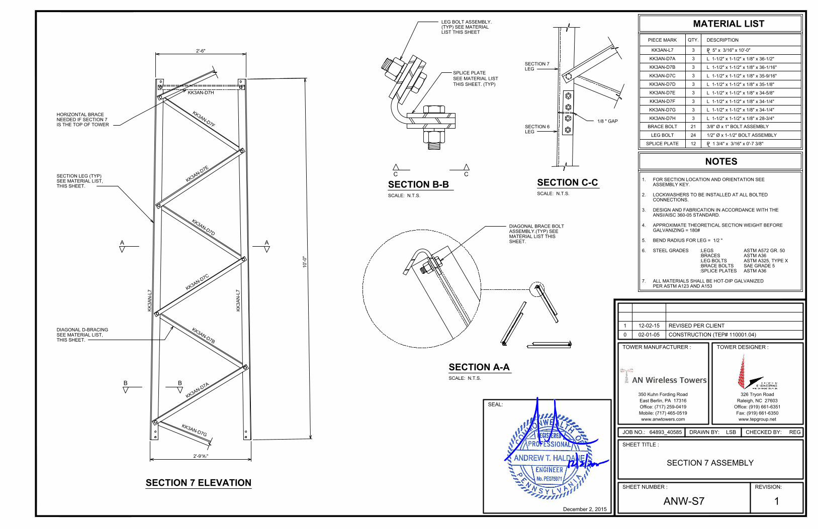
SECTION 7 ELEVATION
KK3AN-L7
KK3AN-D7A
KK3AN-D7B
KK3AN-D7C
KK3AN-D7D
KK3AN-D7E
KK3AN-D7G
QTY.DESCRIPTION
MATERIAL LIST
PIECE MARK
3
3
3
3
3
3
3
3 L 1-1/2" x 1-1/2" x 1/8" x 34-1/4"
KK3AN-D7F
BRACE BOLT
LEG BOLT
SPLICE PLATE
21
24
12
3/8" Ø x 1" BOLT ASSEMBLY
1/2" Ø x 1-1/2" BOLT ASSEMBLY
SECTION LEG (TYP)
SEE MATERIAL LIST,
THIS SHEET.
B B
A A
DIAGONAL D-BRACING
SEE MATERIAL LIST,
THIS SHEET.
10'-0"
K
K
3
A
N
-
D
7
A
K
K
3
A
N
-
D
7
B
K
K
3
A
N
-
D
7
C
K
K
3
A
N
-
D
7
D
K
K
3
A
N
-
D
7
E
K
K
3
A
N
-
D
7
F
KK
3A
N-L7
KK
3A
N-L7
P 5" x 3/16" x 10'-0"
P 1 3/4" x 3/16" x 0'-7 3/8"
KK3AN-D7H
HORIZONTAL BRACE
NEEDED IF SECTION 7
IS THE TOP OF TOWER
KK3AN-D7H 3 L 1-1/2" x 1-1/2" x 1/8" x 28-3/4"
SCALE: N.T.S.
SHEET.
MATERIAL LIST THIS
ASSEMBLY.(TYP) SEE
DIAGONAL BRACE BOLT
SCALE: N.T.S.
SECTION B-B
SCALE: N.T.S.
SECTION C-C
SECTION A-A
LIST THIS SHEET
(TYP) SEE MATERIAL
LEG BOLT ASSEMBLY.
C C
1/8 " GAP
LEG
SECTION 6
LEG
SECTION 7
2'-9
19
32"
2'-6"
L
L 1-1/2" x 1-1/2" x 1/8" x 34-1/4"
L 1-1/2" x 1-1/2" x 1/8" x 34-5/8"
L 1-1/2" x 1-1/2" x 1/8" x 35-1/8"
L 1-1/2" x 1-1/2" x 1/8" x 35-9/16"
L 1-1/2" x 1-1/2" x 1/8" x 36-1/16"
L 1-1/2" x 1-1/2" x 1/8" x 36-1/2"
L
SPLICE PLATE
SEE MATERIAL LIST
THIS SHEET. (TYP)
NOTES
FOR SECTION LOCATION AND ORIENTATION SEE
ASSEMBLY KEY.
LOCKWASHERS TO BE INSTALLED AT ALL BOLTED
CONNECTIONS.
APPROXIMATE THEORETICAL SECTION WEIGHT BEFORE
GALVANIZING = 180#
BEND RADIUS FOR LEG = 1/2 "
STEEL GRADES
:BRACES
:LEG BOLTS
:BRACE BOLTS
ALL MATERIALS SHALL BE HOT-DIP GALVANIZED
PER ASTM A123 AND A153
1.
2.
4.
5.
6.
7.
:LEGS ASTM A572 GR. 50
ASTM A36
:SPLICE PLATES ASTM A36
DESIGN AND FABRICATION IN ACCORDANCE WITH THE
ANSI/AISC 360-05 STANDARD.
3.
K
K
3
A
N
-
D
7
G
ASTM A325, TYPE X
SAE GRADE 5
64893_40585
SEAL:
REGLSB
SHEET TITLE :
SHEET NUMBER : REVISION:
JOB NO.: CHECKED BY:DRAWN BY:
CONSTRUCTION (TEP# 110001.04)0 02-01-05
1
REVISED PER CLIENT1 12-02-15
December 2, 2015
TOWER MANUFACTURER : TOWER DESIGNER :
326 Tryon Road
Raleigh, NC 27603
Office: (919) 661-6351
Fax: (919) 661-6350
350 Kuhn Fording Road
East Berlin, PA 17316
Office: (717) 259-0419
www.tepgroup.netwww.anwtowers.com
Mobile: (717) 465-0519
SECTION 7 ASSEMBLY
ANW-S7

SECTION 8 ELEVATION
KK3AN-L8
KK3AN-D8A
KK3AN-D8B
KK3AN-D8C
KK3AN-D8D
KK3AN-D8E
KK3AN-D8F
KK3AN-D8G L 1-1/2" x 1-1/2" x 1/8" x 31"
QTY. DESCRIPTION
MATERIAL LIST
PIECE MARK
3
3
3
3
3
3
3
3
BRACE BOLT
LEG BOLT
SPLICE PLATE
21
24
12
3/8" Ø x 1" BOLT ASSEMBLY
1/2" Ø x 1 1/2" BOLT ASSEMBLY
SECTION LEG (TYP)
SEE MATERIAL LIST,
THIS SHEET.
B B
A A
DIAGONAL D-BRACING
SEE MATERIAL LIST,
THIS SHEET.
10'-0"
P 1 3/4" x 3/16" x 0'-7 3/8"
K
K
3
A
N
-
D
8
A
K
K
3
A
N
-
D
8
B
K
K
3
A
N
-
D
8
C
K
K
3
A
N
-
D
8
D
K
K
3
A
N
-
D
8
E
K
K
3
A
N
-
D
8
F
KK
3A
N-L8
KK
3A
N-L8
P 5" x 3/16" x 10'-0"
KK3AN-D8H
HORIZONTAL BRACE
NEEDED IF SECTION 8
IS THE TOP OF TOWER
KK3AN-D8H 3 L 1-1/2" x 1-1/2" x 1/8" x 24-15/16"
SCALE: N.T.S.
SHEET.
MATERIAL LIST THIS
ASSEMBLY.(TYP) SEE
DIAGONAL BRACE BOLT
SCALE: N.T.S.
SECTION B-B
SCALE: N.T.S.
SECTION C-C
SECTION A-A
THIS SHEET.(TYP)
SEE MATERIAL LIST
SPLICE PLATE
LIST THIS SHEET
(TYP) SEE MATERIAL
LEG BOLT ASSEMBLY.
C C
L
L
SECTION 8
LEG
SECTION 7
LEG
1/8 " GAP
2'-6"
2'-2
13
32"
L 1-1/2" x 1-1/2" x 1/8" x 31-5/16"
L 1-1/2" x 1-1/2" x 1/8" x 31-3/4"
L 1-1/2" x 1-1/2" x 1/8" x 32-1/8"
L 1-1/2" x 1-1/2" x 1/8" x 32-9/16"
L 1-1/2" x 1-1/2" x 1/8" x 33-1/16"
L 1-1/2" x 1-1/2" x 1/8" x 33-7/16"
NOTES
FOR SECTION LOCATION AND ORIENTATION SEE
ASSEMBLY KEY.
LOCKWASHERS TO BE INSTALLED AT ALL BOLTED
CONNECTIONS.
APPROXIMATE THEORETICAL SECTION WEIGHT BEFORE
GALVANIZING = 172#
BEND RADIUS FOR LEG = 1/2 "
STEEL GRADES
:BRACES
:LEG BOLTS
:BRACE BOLTS
ALL MATERIALS SHALL BE HOT-DIP GALVANIZED
PER ASTM A123 AND A153
1.
2.
4.
5.
6.
7.
:LEGS ASTM A572 GR. 50
ASTM A36
:SPLICE PLATES ASTM A36
DESIGN AND FABRICATION IN ACCORDANCE WITH THE
ANSI/AISC 360-05 STANDARD.
3.
K
K
3
A
N
-
D
8
G
ASTM A325, TYPE X
SAE GRADE 5
64893_40585
SEAL:
REGLSB
SHEET TITLE :
SHEET NUMBER : REVISION:
JOB NO.: CHECKED BY:DRAWN BY:
CONSTRUCTION (TEP# 110001.04)0 02-01-05
1
REVISED PER CLIENT1 12-02-15
December 2, 2015
TOWER MANUFACTURER : TOWER DESIGNER :
326 Tryon Road
Raleigh, NC 27603
Office: (919) 661-6351
Fax: (919) 661-6350
350 Kuhn Fording Road
East Berlin, PA 17316
Office: (717) 259-0419
www.tepgroup.netwww.anwtowers.com
Mobile: (717) 465-0519
SECTION 8 ASSEMBLY
ANW-S8
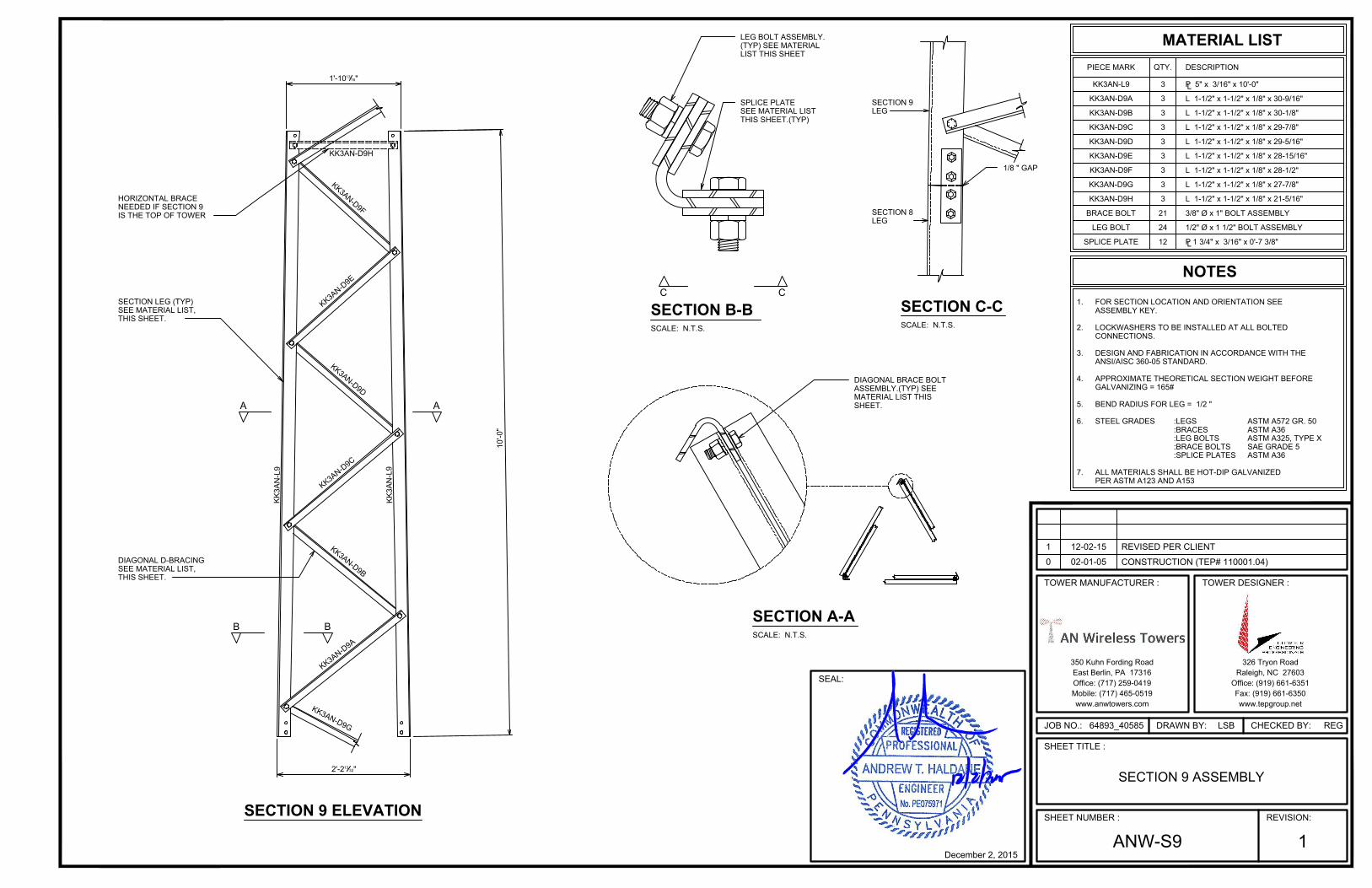
SECTION 9 ELEVATION
KK3AN-L9
KK3AN-D9A
KK3AN-D9B
KK3AN-D9C
KK3AN-D9D
KK3AN-D9E
KK3AN-D9F
KK3AN-D9G
QTY. DESCRIPTION
MATERIAL LIST
PIECE MARK
3
3
3
3
3
3
3
3
BRACE BOLT
LEG BOLT
SPLICE PLATE
21
24
12
3/8" Ø x 1" BOLT ASSEMBLY
1/2" Ø x 1 1/2" BOLT ASSEMBLY
SECTION LEG (TYP)
SEE MATERIAL LIST,
THIS SHEET.
B B
A A
DIAGONAL D-BRACING
SEE MATERIAL LIST,
THIS SHEET.
10'-0"
L 1-1/2" x 1-1/2" x 1/8" x 27-7/8"
K
K
3
A
N
-
D
9
A
K
K
3
A
N
-
D
9
B
K
K
3
A
N
-
D
9
C
K
K
3
A
N
-
D
9
D
K
K
3
A
N
-
D
9
E
K
K
3
A
N
-
D
9
F
KK
3A
N-L9
KK
3A
N-L9
P 5" x 3/16" x 10'-0"
P 1 3/4" x 3/16" x 0'-7 3/8"
KK3AN-D9H
HORIZONTAL BRACE
NEEDED IF SECTION 9
IS THE TOP OF TOWER
KK3AN-D9H 3 L 1-1/2" x 1-1/2" x 1/8" x 21-5/16"
SCALE: N.T.S.
1/8 " GAP
SHEET.
MATERIAL LIST THIS
ASSEMBLY.(TYP) SEE
DIAGONAL BRACE BOLT
SCALE: N.T.S.
SECTION B-B
LEG
SECTION 8
LEG
SECTION 9
SCALE: N.T.S.
SECTION C-C
SECTION A-A
THIS SHEET.(TYP)
SEE MATERIAL LIST
SPLICE PLATE
LIST THIS SHEET
(TYP) SEE MATERIAL
LEG BOLT ASSEMBLY.
C C
L
L
2'-2
13
32"
1'-10
13
16"
L 1-1/2" x 1-1/2" x 1/8" x 28-1/2"
L 1-1/2" x 1-1/2" x 1/8" x 28-15/16"
L 1-1/2" x 1-1/2" x 1/8" x 29-5/16"
L 1-1/2" x 1-1/2" x 1/8" x 29-7/8"
L 1-1/2" x 1-1/2" x 1/8" x 30-1/8"
L 1-1/2" x 1-1/2" x 1/8" x 30-9/16"
K
K
3
A
N
-
D
9
G
NOTES
FOR SECTION LOCATION AND ORIENTATION SEE
ASSEMBLY KEY.
LOCKWASHERS TO BE INSTALLED AT ALL BOLTED
CONNECTIONS.
APPROXIMATE THEORETICAL SECTION WEIGHT BEFORE
GALVANIZING = 165#
BEND RADIUS FOR LEG = 1/2 "
STEEL GRADES
:BRACES
:LEG BOLTS
:BRACE BOLTS
ALL MATERIALS SHALL BE HOT-DIP GALVANIZED
PER ASTM A123 AND A153
1.
2.
4.
5.
6.
7.
:LEGS ASTM A572 GR. 50
ASTM A36
:SPLICE PLATES ASTM A36
DESIGN AND FABRICATION IN ACCORDANCE WITH THE
ANSI/AISC 360-05 STANDARD.
3.
ASTM A325, TYPE X
SAE GRADE 5
64893_40585
SEAL:
REGLSB
SHEET TITLE :
SHEET NUMBER : REVISION:
JOB NO.: CHECKED BY:DRAWN BY:
CONSTRUCTION (TEP# 110001.04)0 02-01-05
1
REVISED PER CLIENT1 12-02-15
December 2, 2015
TOWER MANUFACTURER : TOWER DESIGNER :
326 Tryon Road
Raleigh, NC 27603
Office: (919) 661-6351
Fax: (919) 661-6350
350 Kuhn Fording Road
East Berlin, PA 17316
Office: (717) 259-0419
www.tepgroup.netwww.anwtowers.com
Mobile: (717) 465-0519
SECTION 9 ASSEMBLY
ANW-S9
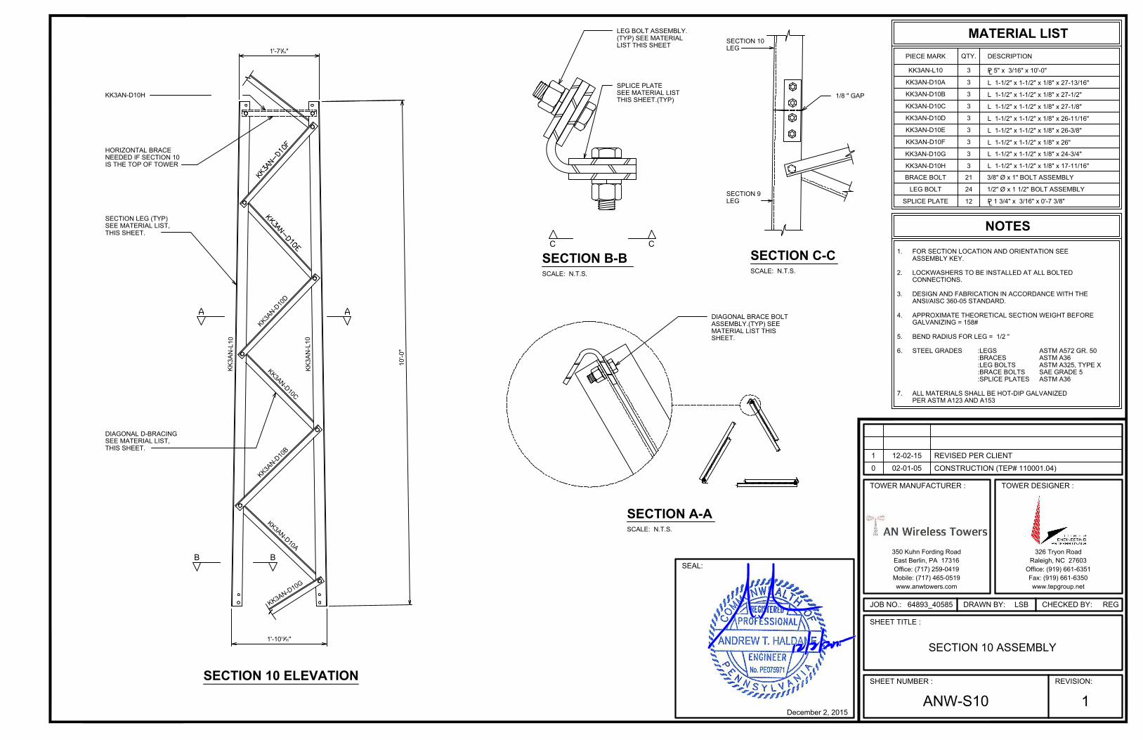
SECTION 10 ELEVATION
QTY. DESCRIPTION
MATERIAL LIST
PIECE MARK
3
3
3
3
3
3
3
KK3AN-L10
KK3AN-D10A
KK3AN-D10B
KK3AN-D10C
KK3AN-D10D
KK3AN-D10E
KK3AN-D10F
BRACE BOLT
LEG BOLT
SPLICE PLATE
21
24
12
3 L 1-1/2" x 1-1/2" x 1/8" x 24-3/4" KK3AN-D10G
3/8" Ø x 1" BOLT ASSEMBLY
1/2" Ø x 1 1/2" BOLT ASSEMBLY
SECTION LEG (TYP)
SEE MATERIAL LIST,
THIS SHEET.
B B
DIAGONAL D-BRACING
SEE MATERIAL LIST,
THIS SHEET.
10'-0"
K
K
3
A
N
-
D
1
0
A
K
K
3
A
N
-
D
1
0
B
K
K
3
A
N
-
D
1
0
C
K
K
3
A
N
-
D
1
0
D
KK
3A
N-L10
KK
3A
N-L10
P 5" x 3/16" x 10'-0"
P 1 3/4" x 3/16" x 0'-7 3/8"
KK3AN-D10H
HORIZONTAL BRACE
NEEDED IF SECTION 10
IS THE TOP OF TOWER
KK3AN-D10H 3 L 1-1/2" x 1-1/2" x 1/8" x 17-11/16"
SCALE: N.T.S.
SHEET.
MATERIAL LIST THIS
ASSEMBLY.(TYP) SEE
DIAGONAL BRACE BOLT
SCALE: N.T.S.
SECTION B-B
SCALE: N.T.S.
SECTION C-C
SECTION A-A
THIS SHEET.(TYP)
SEE MATERIAL LIST
SPLICE PLATE
LIST THIS SHEET
(TYP) SEE MATERIAL
LEG BOLT ASSEMBLY.
C C
L
L
1'-10
13
16"
1'-7
3
16"
L 1-1/2" x 1-1/2" x 1/8" x 26"
L 1-1/2" x 1-1/2" x 1/8" x 26-3/8"
L 1-1/2" x 1-1/2" x 1/8" x 26-11/16"
L 1-1/2" x 1-1/2" x 1/8" x 27-1/8"
L 1-1/2" x 1-1/2" x 1/8" x 27-1/2"
L 1-1/2" x 1-1/2" x 1/8" x 27-13/16"
1/8 " GAP
LEG
SECTION 9
LEG
SECTION 10
NOTES
FOR SECTION LOCATION AND ORIENTATION SEE
ASSEMBLY KEY.
LOCKWASHERS TO BE INSTALLED AT ALL BOLTED
CONNECTIONS.
APPROXIMATE THEORETICAL SECTION WEIGHT BEFORE
GALVANIZING = 158#
BEND RADIUS FOR LEG = 1/2 "
STEEL GRADES
:BRACES
:LEG BOLTS
:BRACE BOLTS
ALL MATERIALS SHALL BE HOT-DIP GALVANIZED
PER ASTM A123 AND A153
1.
2.
4.
5.
6.
7.
:LEGS ASTM A572 GR. 50
ASTM A36
:SPLICE PLATES ASTM A36
DESIGN AND FABRICATION IN ACCORDANCE WITH THE
ANSI/AISC 360-05 STANDARD.
3.
K
K
3
A
N
-
D
1
0
G
ASTM A325, TYPE X
SAE GRADE 5
64893_40585
SEAL:
REGLSB
SHEET TITLE :
SHEET NUMBER : REVISION:
JOB NO.: CHECKED BY:DRAWN BY:
CONSTRUCTION (TEP# 110001.04)0 02-01-05
1
REVISED PER CLIENT1 12-02-15
December 2, 2015
TOWER MANUFACTURER : TOWER DESIGNER :
326 Tryon Road
Raleigh, NC 27603
Office: (919) 661-6351
Fax: (919) 661-6350
350 Kuhn Fording Road
East Berlin, PA 17316
Office: (717) 259-0419
www.tepgroup.netwww.anwtowers.com
Mobile: (717) 465-0519
SECTION 10 ASSEMBLY
ANW-S10
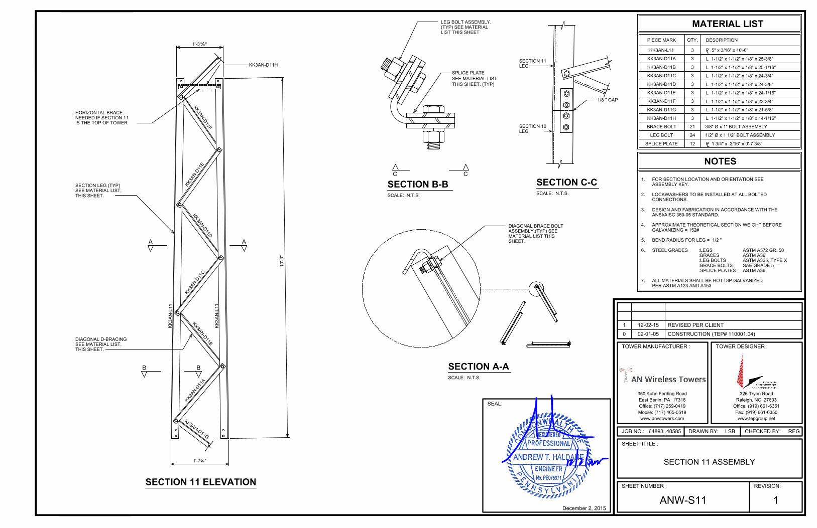
SECTION 11 ELEVATION
QTY. DESCRIPTION
MATERIAL LIST
PIECE MARK
3
3
3
3
3
3
3
KK3AN-L11
KK3AN-D11A
KK3AN-D11B
KK3AN-D11C
KK3AN-D11D
KK3AN-D11E
KK3AN-D11F
P 5" x 3/16" x 10'-0"
BRACE BOLT
LEG BOLT
21
24
KK3AN-D11G 3 L 1-1/2" x 1-1/2" x 1/8" x 21-5/8"
3/8" Ø x 1" BOLT ASSEMBLY
1/2" Ø x 1 1/2" BOLT ASSEMBLY
SECTION LEG (TYP)
SEE MATERIAL LIST,
THIS SHEET.
B B
A A
DIAGONAL D-BRACING
SEE MATERIAL LIST,
THIS SHEET.
10'-0"
SPLICE PLATE 12
1'-3
19
32"
1'-7
3
16"
K
K
3
A
N
-
D
1
1
A
K
K
3
A
N
-
D
1
1
B
K
K
3
A
N
-
D
1
1
C
K
K
3
A
N
-
D
1
1
D
K
K
3
A
N
-
D
1
1
E
K
K
3
A
N
-
D
1
1
F
KK
3A
N-L11
KK
3A
N-L11
P 1 3/4" x 3/16" x 0'-7 3/8"
KK3AN-D11H
KK3AN-D11H 3 L 1-1/2" x 1-1/2" x 1/8" x 14-1/16"
HORIZONTAL BRACE
NEEDED IF SECTION 11
IS THE TOP OF TOWER
SCALE: N.T.S.
1/8 " GAP
SHEET.
MATERIAL LIST THIS
ASSEMBLY.(TYP) SEE
DIAGONAL BRACE BOLT
SCALE: N.T.S.
SECTION B-B
LEG
SECTION 10
LEG
SECTION 11
SCALE: N.T.S.
SECTION C-C
SECTION A-A
LIST THIS SHEET
(TYP) SEE MATERIAL
LEG BOLT ASSEMBLY.
C C
L
L
L 1-1/2" x 1-1/2" x 1/8" x 23-3/4"
L 1-1/2" x 1-1/2" x 1/8" x 24-1/16"
L 1-1/2" x 1-1/2" x 1/8" x 24-3/8"
L 1-1/2" x 1-1/2" x 1/8" x 24-3/4"
L 1-1/2" x 1-1/2" x 1/8" x 25-1/16"
L 1-1/2" x 1-1/2" x 1/8" x 25-3/8"
SPLICE PLATE
SEE MATERIAL LIST
THIS SHEET. (TYP)
NOTES
FOR SECTION LOCATION AND ORIENTATION SEE
ASSEMBLY KEY.
LOCKWASHERS TO BE INSTALLED AT ALL BOLTED
CONNECTIONS.
APPROXIMATE THEORETICAL SECTION WEIGHT BEFORE
GALVANIZING = 152#
BEND RADIUS FOR LEG = 1/2 "
STEEL GRADES
:BRACES
:LEG BOLTS
:BRACE BOLTS
ALL MATERIALS SHALL BE HOT-DIP GALVANIZED
PER ASTM A123 AND A153
1.
2.
4.
5.
6.
7.
:LEGS ASTM A572 GR. 50
ASTM A36
:SPLICE PLATES ASTM A36
DESIGN AND FABRICATION IN ACCORDANCE WITH THE
ANSI/AISC 360-05 STANDARD.
3.
K
K
3
A
N
-
D
1
1
G
ASTM A325, TYPE X
SAE GRADE 5
64893_40585
SEAL:
REGLSB
SHEET TITLE :
SHEET NUMBER : REVISION:
JOB NO.: CHECKED BY:DRAWN BY:
CONSTRUCTION (TEP# 110001.04)0 02-01-05
1
REVISED PER CLIENT1 12-02-15
December 2, 2015
TOWER MANUFACTURER : TOWER DESIGNER :
326 Tryon Road
Raleigh, NC 27603
Office: (919) 661-6351
Fax: (919) 661-6350
350 Kuhn Fording Road
East Berlin, PA 17316
Office: (717) 259-0419
www.tepgroup.netwww.anwtowers.com
Mobile: (717) 465-0519
SECTION 11 ASSEMBLY
ANW-S11

SECTION 12 ELEVATION
QTY.DESCRIPTION
MATERIAL LIST
PIECE MARK
3
3
3
3
3
3
3
KK3AN-D12A
KK3AN-D12B
KK3AN-D12C
KK3AN-D12D
KK3AN-D12E
KK3AN-D12F
P 5" x 3/16" x 10'-0"
BRACE BOLT
LEG BOLT
SPLICE PLATE
24
24
12
3KK3AN-D12G
3/8" Ø x 1" BOLT ASSEMBLY
1/2" Ø x 1-1/2" BOLT ASSEMBLY
KK3AN-L12
L 1-1/2" x 1-1/2" x 1/8" x 18-7/8"
SECTION LEG (TYP)
SEE MATERIAL LIST,
THIS SHEET.
B B
A A
DIAGONAL D-BRACING
SEE MATERIAL LIST,
THIS SHEET.
10'-0"
1'-0"
1'-3
19
32"
K
K
3
A
N
-
D
1
2
A
K
K
3
A
N
-
D
1
2
B
K
K
3
A
N
-
D
1
2
C
K
K
3
A
N
-
D
1
2
D
K
K
3
A
N
-
D
1
2
E
K
K
3
A
N
-
D
1
2
F
KK3AN-D12H
KK
3A
N-L12
KK
3A
N-L12
P 1-3/4" x 3/16" x 0'-7 3/8"
SCALE: N.T.S.
SHEET.
MATERIAL LIST THIS
ASSEMBLY.(TYP) SEE
DIAGONAL BRACE BOLT
SCALE: N.T.S.
SECTION B-B
SCALE: N.T.S.
SECTION C-C
SECTION A-A
THIS SHEET.(TYP)
SEE MATERIAL LIST
SPLICE PLATE
LIST THIS SHEET
(TYP) SEE MATERIAL
LEG BOLT ASSEMBLY.
C C
L
L
L 1-1/2" x 1-1/2" x 1/8" x 21-7/8"
L 1-1/2" x 1-1/2" x 1/8" x 22-1/8"
L 1-1/2" x 1-1/2" x 1/8" x 22-3/8"
L 1-1/2" x 1-1/2" x 1/8" x 22-5/8"
L 1-1/2" x 1-1/2" x 1/8" x 22-15/16"
L 1-1/2" x 1-1/2" x 1/8" x 23-3/16"
1/8 " GAP
LEG
SECTION 11
LEG
SECTION 12
NOTES
FOR SECTION LOCATION AND ORIENTATION SEE
ASSEMBLY KEY.
LOCKWASHERS TO BE INSTALLED AT ALL BOLTED
CONNECTIONS.
APPROXIMATE THEORETICAL SECTION WEIGHT BEFORE
GALVANIZING = 146#
BEND RADIUS FOR LEG = 1/2 "
STEEL GRADES
:BRACES
:LEG BOLTS
:BRACE BOLTS
ALL MATERIALS SHALL BE HOT-DIP GALVANIZED
PER ASTM A123 AND A153
1.
2.
4.
5.
6.
7.
:LEGS ASTM A572 GR. 50
ASTM A36
:SPLICE PLATES ASTM A36
DESIGN AND FABRICATION IN ACCORDANCE WITH THE
ANSI/AISC 360-05 STANDARD.
3.
3KK3AN-D12H L 1-1/2" x 1-1/2" x 1/8" x 10-1/2"
KK3AN-D12G
ASTM A325, TYPE X
SAE GRADE 5
64893_40585
SEAL:
REGLSB
SHEET TITLE :
SHEET NUMBER : REVISION:
JOB NO.: CHECKED BY:DRAWN BY:
CONSTRUCTION (TEP# 110001.04)0 02-01-05
1
REVISED PER CLIENT1 12-02-15
December 2, 2015
TOWER MANUFACTURER : TOWER DESIGNER :
326 Tryon Road
Raleigh, NC 27603
Office: (919) 661-6351
Fax: (919) 661-6350
350 Kuhn Fording Road
East Berlin, PA 17316
Office: (717) 259-0419
www.tepgroup.netwww.anwtowers.com
Mobile: (717) 465-0519
SECTION 12 ASSEMBLY
ANW-S12

Concrete Base Section

Concrete Base Section

Concrete Base Section
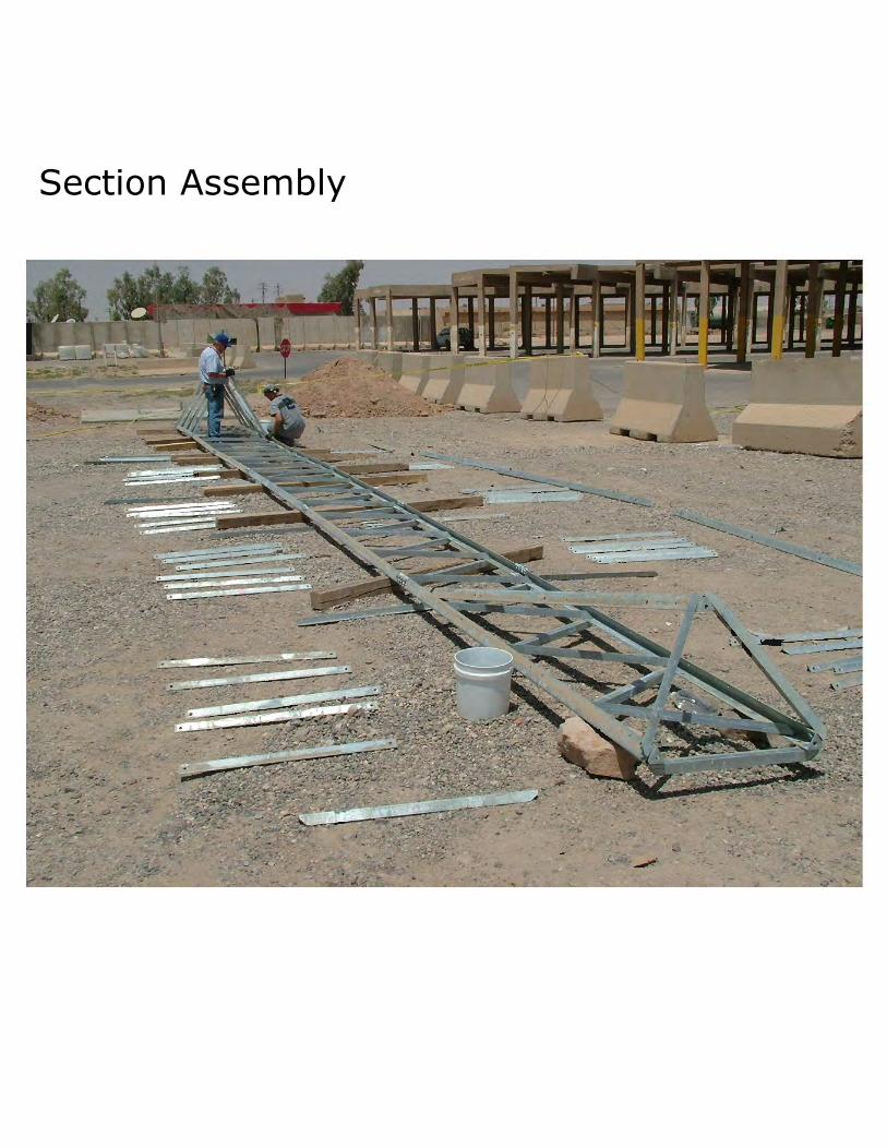
Section Assembly

Section Assembly

Splice Plate Leg Connection
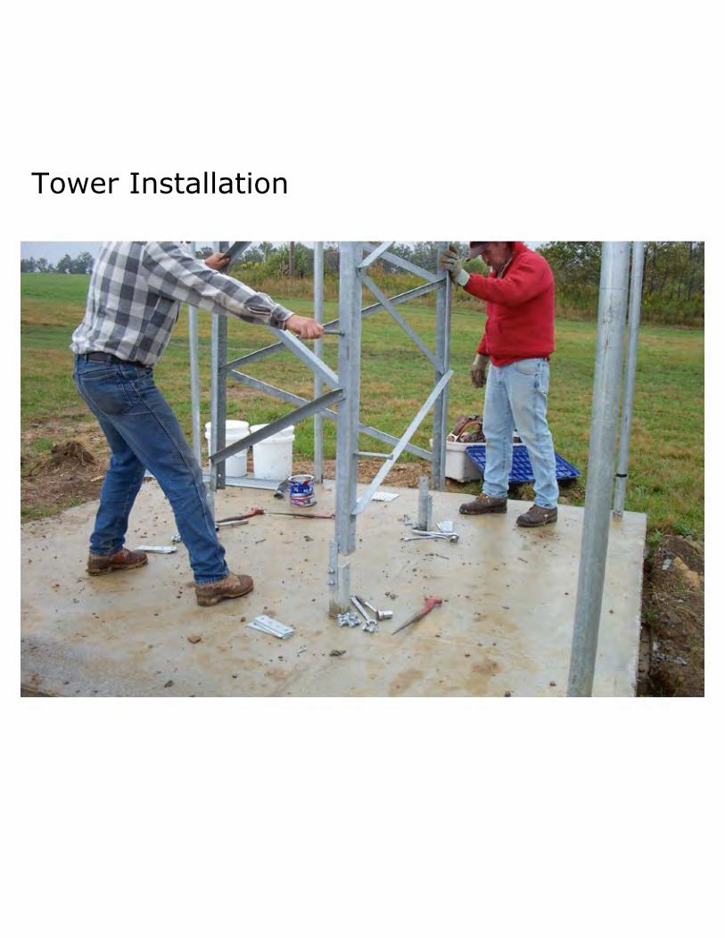
Tower Installation

Tower Installation

Step Bolts

Plate Mounts (3)

Fixed-Mount Mast Plate

Thrust Bearing Plate

Rotator / Thrust Bearing Plates

Rotator / Thrust Bearing Plates

Anti-Climb Panels
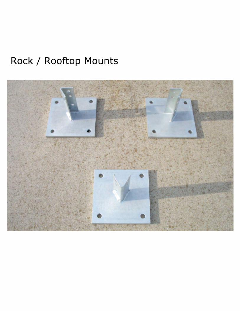
Rock / Rooftop Mounts

Tower Grounding Kit