An Urgent Bulletin from CSA International · 2017-07-12 · A DC-AFPD is intended to detect and...
22
Visit us at www.csagroup.org Click on "Contact Us" for the online phone listing of our Offices and Partners DQD 529.02 Rev 2012-03-10 Page 1 of 22 I:\Wgm4\DOC_CTRL\INFORMS\A-D\Arc-FaultProtection01.doc Ref No: I13-031 Arc-Fault Protection No. 1 New Service available as of today Date: March 11, 2013 Apply any time to have your products evaluated Announcing: Publication of TIL M-07, Interim Certification Requirements for Photovoltaic (PV) DC Arc-Fault Protection (DC-AFP) Class No: 1432 02, CIRCUIT BREAKERS - Arc Fault Circuit Interrupters To purchase the Standard, visit us at www.shopcsa.ca Who is affected? Manufacturers of Photovoltaic (PV) DC Arc- Fault Protection (DC-AFP) and PV-related equipment. What do you do? 1. This publication provides for new certification services that do not affect your currently certified product designs. 2. Please contact CSA engineering staff if you have questions or need information concerning this publication and how it applies to you. 3. If you would like to take advantage of the new certification services, initiate a certification project by contacting our Client Services Centre at 1-866-797-4272. Please supply appropriate supporting documentation* and we will inform you of the samples required. *which includes technical information, company name, address, factory locations and CSA file number or master contract number (if assigned), and any other relevant documentation. Introduction: Should this T.I.L. not be incorporated into the standard within five (5) years, it may be withdrawn and certifications will be cancelled. Background and Rationale: At the request of Canadian Regulatory Authorities and Industry Stakeholders, CSA has published T.I.L. M-07, Interim Certification Requirements for Photovoltaic (PV) DC Arc-Fault Protection (DC-AFP) to address the safety concerns of DC arc faults associated with Photovoltaic (PV) Systems. The T.I.L. is attached as Attachment 1 in this Informs. For questions specific to your file or products contact your regular CSA International engineering staff. Go to http://directories.csa-international.org/ and enter your Master Contract # and the class numbers associated with this Informs to view your certified products. For technical questions on this Informs Contact Tim Evans by phone 416.747.2708, fax 416.747.4149 or e-mail [email protected] An Urgent Bulletin from CSA International
Transcript of An Urgent Bulletin from CSA International · 2017-07-12 · A DC-AFPD is intended to detect and...

Visit us at www.csagroup.org Click on "Contact Us" for the online phone listing of our Offices and Partners
DQD 529.02 Rev 2012-03-10
Page 1 of 22 I:\Wgm4\DOC_CTRL\INFORMS\A-D\Arc-FaultProtection01.doc
Ref No: I13-031 Arc-Fault Protection No. 1 New Service available as of today Date: March 11, 2013 Apply any time to have your products evaluated
Announcing: Publication of TIL M-07, Interim Certification Requirements for Photovoltaic (PV) DC Arc-Fault Protection (DC-AFP)
Class No: 1432 02, CIRCUIT BREAKERS - Arc Fault Circuit Interrupters
To purchase the Standard, visit us at www.shopcsa.ca
Who is affected? Manufacturers of Photovoltaic (PV) DC Arc-Fault Protection (DC-AFP) and PV-related equipment.
What do you do? 1. This publication provides for new
certification services that do not affect your currently certified product designs.
2. Please contact CSA engineering staff if you have questions or need information concerning this publication and how it applies to you.
3. If you would like to take advantage of the new certification services, initiate a certification project by contacting our Client Services Centre at 1-866-797-4272. Please supply appropriate supporting documentation* and we will inform you of the samples required.
*which includes technical information, company name, address, factory locations and CSA file number or master contract number (if assigned), and any other relevant documentation.
Introduction: Should this T.I.L. not be incorporated into the standard within five (5) years, it may be withdrawn and certifications will be cancelled.
Background and Rationale: At the request of Canadian Regulatory Authorities and Industry Stakeholders, CSA has published T.I.L. M-07, Interim Certification Requirements for Photovoltaic (PV) DC Arc-Fault Protection (DC-AFP) to address the safety concerns of DC arc faults associated with Photovoltaic (PV) Systems. The T.I.L. is attached as Attachment 1 in this Informs.
For questions specific to your file or products contact your regular CSA International engineering staff.
Go to http://directories.csa-international.org/ and enter your Master Contract # and the class numbers associated with this Informs to
view your certified products.
For technical questions on this Informs
Contact Tim Evans by phone 416.747.2708, fax 416.747.4149
or e-mail [email protected]
An Urgent Bulletin from CSA International

DQD 529.02 Rev 2012-03-10 Page 2 of 22 I:\Wgm4\DOC_CTRL\INFORMS\A-D\Arc-FaultProtection01.doc
ATTACHMENT 1
TECHNICAL INFORMATION LETTER NO. M-07
CSA Group
Product Group: Industrial Control and Power Distribution Date: March 11, 2013 Issued by: Tim Evans Approved by: John Jakob EQUIPMENT: Industrial Control Equipment ITEM: Interim Certification Requirements for Photovoltaic (PV) DC Arc-Fault Protection (DC-AFP)
STANDARDS: See Clause 3. Applicable Standards BACKGROUND AND RATIONALE At the request of Canadian Regulatory Authorities and Industry Stakeholders, CSA International has developed a set of interim certification requirements to address the safety concerns of DC arc faults associated with Photovoltaic (PV) Systems. 1 SCOPE
This Technical Information Letter (T.I.L.) applies to DC arc-fault protective-devices (DC-AFPDs) and devices incorporating arc-fault circuit protection intended for use in direct current circuits having a maximum voltage rating of 1000V. A DC-AFPD is intended to detect and mitigate the effects of arcing faults, which may pose a risk of fire ignition under certain conditions if the arcing persists. A DC-AFPD is not intended to detect glowing connections. If the functional component that performs the AFPD function is intended to also perform other functions, such as overload protection, short-circuit protection, ground fault circuit interruption, surge suppression, other similar functions, or any combination thereof, it shall comply additionally with the requirements of the applicable CSA Standard or Standards that cover devices that provide those functions. This Technical Information Letter contains construction, test and marking requirements for DC-AFPDs and shall be used in conjunction with CSA Standards CAN/CSA-C22.2 No. 5, CAN/CSA-C22.2 No. 144.1, and C22.2 No. 107.1 as applicable.
2 DEFINITIONS 2.1 The following definitions apply in this Technical Information Letter.
ARCING – A luminous discharge of electricity across an insulating medium, usually accompanied by the partial volatilization of the electrodes. ARCING FAULT – An unintentional arcing condition in a circuit. Photovoltaic (PV) DC -ARC-FAULT circuit interrupter (DC-AFCI) – A device intended to detect unintended arcing and to provide a current interruption function. Photovoltaic (PV) DC-arc fault detector (DC-AFD) – A device intended to detect unintended arcing and enable an interrupting or photovoltaic shunting device.

DQD 529.02 Rev 2012-03-10 Page 3 of 22 I:\Wgm4\DOC_CTRL\INFORMS\A-D\Arc-FaultProtection01.doc
Photovoltaic (PV) DC interrupting device – A device that is intended to interrupt a detected arcing fault. CARBONIZED PATH – A conductive or potentially conductive carbon path formed through or over the surface of a normally insulating material. OPERATION INHIBITION – Denotes the concealment of an arc-fault by the normal operation of certain circuit components. PARALLEL ARCING – Arcing that occurs between live conductors or between a live conductor and ground and is in parallel with the load. UNWANTED TRIP – A tripping function in response to an arcing condition that is not an arc-fault but a condition that occurs as part of the normal or anticipated operation of circuit components. SERIES ARCING – Arcing that occurs within a conductor in series with the load due to some irregularity in the conductor path.
3 APPLICABLE STANDARDS
CSA Standards: CSA C22.2 No. 0-10 - General Requirements – Canadian Electrical Code, Part II CSA C22.2 No. 0.2-93 - Insulation Coordination CAN/CSA-C22.2 No. 0.4-04 - Bonding of Electrical Equipment CSA C22.2 No. 0.8-09 - Safety functions incorporating electronic technology CAN/CSA-C22.2 No. 0.17-00 - Evaluation of Properties of Polymeric Materials CSA C22.2 No. 5-09 - Molded-Case Circuit Breakers, Molded-Case Switches, and Circuit-Breaker
Enclosures CAN/CSA-C22.2 No. 65-03 - Wire Connectors CAN/CSA-C22.2 No. 94.1-07 - Enclosures for Electrical Equipment, Non-Environmental Considerations CAN/CSA-C22.2 No. 94.2-07 - Enclosures for Electrical Equipment, Environmental Considerations CSA C22.2 No. 107.1-01 - General Use Power Supplies CAN/CSA-C22.2 No. 144.1-06 - Ground-Fault Circuit-Interrupters IEC 61000-4-5 - Electromagnetic Compatibility (EMC) Part 4-5: Testing and Measurements
Techniques – Surge Immunity Test 4 GENERAL 4.1 A DC-AFPD that has additional functions shall comply with the requirements of the CSA Standard applicable to
that additional function. 4.2 A DC-AFPD that has tripped in accordance with the performance provisions of this T.I.L. shall not be capable of
automatic reclosure. 4.3 A DC-AFCI and a DC-AFD shall be provided with an automatic test circuit that regularly, at specific intervals,
simulates the arc detection circuitry output to exercise the arc detection portion of the device. If the automatic test circuit senses a failure, then the interrupter (AFCI) or output (AFD) shall open or activate.
4.4 A DC-AFPD shall be provided with a manual test function that simulates the arc detection circuitry and validates
the functionality of the detection output and circuit interruption function. The results of the test shall be made known to the user by a positive, visual indication.
4.5 Spacings
4.5.1 DC-AFPD’s shall meet the electrical spacing requirements of the end product standard with which they are associated in addition to the spacings indicated in Table 4.5.1.

DQD 529.02 Rev 2012-03-10 Page 4 of 22 I:\Wgm4\DOC_CTRL\INFORMS\A-D\Arc-FaultProtection01.doc
Table 4.5.1 Minimum spacings in millimetresc,d
Voltage between
parts
At terminals Other than at terminals
Between terminals of opposite polarity
Between terminals and any grounded
metala
Between uninsulated live
parts of opposite polarityb
Between uninsulated live parts and any ground metala
A B C D
Through Air
Over Surface
Through Air
Over Surface
Through Air
Over Surface
Through Air
Over Surface
0 – 130 12.7 19.1 12.7 12.7 6.4 9.5 6.4 9.5 131 – 300 19.1 31.8 12.7 12.7 6.4 9.5 6.4 9.5 301 – 600 25.4 50.8 12.7 25.4 9.5 12.7 9.5 12.7 601 – 1000 38.1 63.5 38.1 50.8 9.5 12.7 9.5 12.7 a) The spacing to the enclosure or mounting means shall be permitted to be reduced if an acceptable liner of
insulating material, not less than 0.8 mm (1/32 inch) thick, is used to provide the required spacing through air. b) See Table 4.6.2 for spacings between parts of opposite polarity on a control circuit printed wiring board with
conformal coating. c) In measuring an over surface spacing, any slot, groove, or the like, 0.33 mm (0.013 inch) wide or less in the
contour of insulating material shall be disregarded. d) In measuring spacings, an air spacing of 0.33 mm (0.013 inch) or less between a live part and an insulating
surface shall be disregarded, and the live part considered in contact with the insulating material. 4.5.2 The spacings on a printed circuit board assembly that contains only the DC-AFPD circuitry shall be permitted to
be less than indicated in Table 4.5.1 if a conformal coating and spacings are utilized in compliance with the requirements described in Table 4.5.2. The coated printed wiring assembly shall comply with the requirements for coated printed circuit board test in CSA standard C22.2 No. 0.2, Insulation Coordination as outlined in Clause 4.6. A coating shall not be required if the voltage is 50 V or less and the board is located so that it is not readily subject to contamination by dust.
Table 4.5.2 Minimum opposite polarity spacings on printed-wiring assemblies with conformal coatingsa
Voltage between parts Power available
Minimum spacings
mm Inch
0 - 600 Unlimited 0.8 (1/32) 0 - 30 Limited (class 2 circuits) 0.4 (1/64)
a) Minimum spacing between live parts of opposite polarity. Spacing between live parts and dead metal shall comply with Table 6.
4.6 In conducting evaluations in accordance with the requirements in CSA Standard C22.2 No. 0.2, Insulation
Coordination, the following guidelines shall be used:
a) Unless specified elsewhere in this T.I.L., the pollution degree shall be considered to be Pollution Degree 3. b) Circuits, which operate in the direct line of the source of power, shall be considered to be Overvoltage
Category III. Other circuits shall be considered to be Overvoltage Category II. c) Pollution Degree 2 shall be considered to exist on a printed circuit board between adjacent conductive
material, which is covered by any coating, which provides an uninterrupted covering over at least one side, and the complete distance up to the other side of conductive material.
d) A printed circuit board shall be considered to be Material Group III-b (CTI of 100 to 175) without further investigation. For printed circuit boards of Material Groups I, II or III-a, the requirements of CSA Standard CAN/CSA-C22.2 No. 0.17, Evaluation of Properties of Polymeric Materials, Clause 6.5 shall be applied.
e) For the purposes of compliance with the requirements for coatings of printed circuit boards used to achieve pollution degree 1 in accordance with CSA Standard C22.2 No. 0.2, a coating, which complies with the

DQD 529.02 Rev 2012-03-10 Page 5 of 22 I:\Wgm4\DOC_CTRL\INFORMS\A-D\Arc-FaultProtection01.doc
requirements of Clause 5.4 of CSA Standard C22.2 No. 0.2, shall be acceptable. f) Overvoltage protection, when provided, shall comply with the requirements of Clauses 4.2.4 and 4.2.5 of CSA
Standard C22.2 No. 0.2. Surge suppressors of the Metal Oxide Varistor type shall not be considered to be acceptable overvoltage protection for equipment and circuits which operate in the direct line of the source of power (Overvoltage Category III).
g) Creepages shall be evaluated in accordance with Clause 4.3 of CSA Standard C22.2 No. 0.2. h) Assemblies that are designed to ensure micro-environments of Pollution Degree 1 or 2 as defined in CSA
Standard C22.2 No. 0.2 shall be evaluated in accordance with the requirements for that micro-environment. Examples of accepted measures to control micro-environments include potting and sealing for Pollution Degree 1 and dust covers for Pollution Degree 2.
4.7 For DC-AFCIs that are designed to interrupt the circuit upon detection of a fault, the DC-AFCI contacts shall open
the ungrounded circuit conductors simultaneously in the event of an arcing fault. 4.8 An enclosure, if provided, shall meet the applicable requirements of CSA Standards C22.2 No. 94.1 and 94.2. 4.9 DC-AFCIs shall meet the general requirements outlined in CSA Standard C22.2 No. 0. 4.10 Where applicable, DC-AFPDs shall meet the requirements of CSA Standard CAN/CSA-C22.2 No. 0.4. 4.11 Pressure-type wiring terminals shall comply with CAN/CSA-C22.2 No. 65. 5 PERFORMANCE 5.1 General A DC-AFCI shall comply with the performance requirements in Clause 5 as detailed in Tables 5.1.1 and 5.1.2.
Table 5.1.1 Test Sequence
Clause Test name No. 1
Conditioning/ environmentala
No. 2 Overload/
enduranceb
No. 3 Otherc
Conditioning 5.2 Humidity X 5.3 Voltage Surge X 5.4 Surge Current X 5.5 Abnormal Overvoltage X 5.6 Arc-fault Detectionf Xf 5.15 Abnormal Operationd, e X d, e 5.16 Short Circuit Current X 5.11 Normal Temperature X 5.12 Overvoltage X 5.13 Overload X 5.14 Endurance X 5.9 Dielectric Withstand X X X 5.7 Unwanted Tripping X 5.8 Operation Inhibition X
5.10 Immunity to conducted disturbances, induced by RF fields X
5.19 Corrosion X 5.17 Terminal Lead Strain-Relief X 5.18 Mechanical X
a) The same representative DC-AFPD shall be subjected to the tests for the sequence shown in Col. No. 1. b) The same representative DC-AFPD shall be subjected to all of the tests in the sequence shown in Col. No. 2. c) These tests shown in Col. No. 3 need not be conducted in the sequence shown and may be conducted on new
representative DC-AFPDs, except when the dielectric voltage withstand is required as part of another test. d) The abnormal test(s) shall be permitted to be performed on new samples or sub-assemblies as specified in

DQD 529.02 Rev 2012-03-10 Page 6 of 22 I:\Wgm4\DOC_CTRL\INFORMS\A-D\Arc-FaultProtection01.doc
clause 5.15(a). e) The dielectric strength test is performed only as required to show compliance with clauses 5.15 (a), (d). f) See Table 2 for the sequence of the Arc-fault detection Tests.
Table 5.1.2 Arc-Fault Detection Tests Table
Clause Tests
5.6.2 Series Connection Arcing Test 5.6.3 Parallel Path Arcing Test 5.7 Unwanted Tripping Tests
5.7.2 Loading Condition I – Inverters, Converters, and Charge Controllers 5.7.2 Loading condition II – DC switch operation 5.7.3 Loading Condition II – DC Switch Operation 5.8 Operation Inhibition Tests
5.8.2 Masking the signal to operate 5.8.3 Line impedance
5.2 Humidity Conditioning A representative DC-AFPD shall be exposed for 168 hr to air at a relative humidity of 93 ± 2%, at a temperature of
32.0 ± 2°C. The device shall be exposed to ambient air at a temperature of at least 30°C until thermal equilibrium is attained before being placed in the test chamber.
5.3 Voltage Surge Test 5.3.1 General 5.3.1.1 The supply terminals that are protected by the representative arc-fault protective-device shall be subjected to the
surge tests in accordance with the sequence described in Table 5.3.1.1. Previously untested representative arc-fault protective-devices shall be tested as specified in the Surge current test, Clause 5.4, and the abnormal overvoltage test, Clause 5.5.
Table 5.3.1.1 Voltage surge test sequence
Test Reference Clause
Unwanted Tripping Test 5.3.2 Surge Immunity Test 5.3.3 Surge Current Test 5.4
Abnormal Overvoltage Test 5.5 5.3.1.2 The arc-fault protective-device is to be connected to a supply of rated voltage with the correct polarity maintained.
The arc-fault protective-device is to be in the "on" condition with no load connected. AFPDs that are intended only for use in enclosures shall be tested in their intended enclosure for the tests referenced in 5.3.1.1. The enclosure shall be representative of the worst case situation for the tests.
5.3.2 Unwanted Tripping Test (Ring Wave) 5.3.2.1 One representative AFCI/AFD shall not trip after being subjected to ten random applications or three controlled
applications of a 3 kV surge applied at 60 second intervals. When the AFCI/AFD is subjected to the three controlled applications, one application is to be essentially at zero of the supply voltage wave, one at the positive peak, and one at the negative peak.
5.3.2.2 The surge generator is to have a surge impedance of 50 ohms. When there is no load on the generator, the
waveform of the surge is to be essentially as follows:
a) Initial rise time, 0.5 microseconds between 10 percent and 90 percent of peak amplitude, b) The period of the following oscillatory wave, 10 microseconds, and

DQD 529.02 Rev 2012-03-10 Page 7 of 22 I:\Wgm4\DOC_CTRL\INFORMS\A-D\Arc-FaultProtection01.doc
c) Each successive peak, 60 percent of the preceding peak. 5.3.2.3 Figures 5.3.1 and 5.3.2 show a typical surge generator and control relay.
Figure 5.3.1 Surge generator circuit
C1 = 0.025 μF, 10 kV C2 = 0.02 μF, 10 kV C3 = 4 μF, 400V L1 = 15 μH [23 turns, 0.258 mm2 (23 AWG wire), 18 mm (0.7 inch) diameter air core] L2 = 70 μH [28 turns, 0.258 mm2 (23 AWG) wire, 66 MM (2.6 inch) diameter air core] R1 = 22 Ohms, 1 W, composition R2 = 12 Ohms, 1W, composition R3 = 1.3M Ohms (12 x 110K Ohms, 1/2 W) R4 = 47K Ohms (10 x 4.7K Ohms, 1/2 W) R5 = 200 Ohms, 1/2 W CR-1 = Relay

DQD 529.02 Rev 2012-03-10 Page 8 of 22 I:\Wgm4\DOC_CTRL\INFORMS\A-D\Arc-FaultProtection01.doc
Figure 5.3.2 Relay control circuit for surge generator
R1 = 10K Ohms, 1 W R2 = 1K Ohms, 1/2 W R3 = 1K Ohms, 1/2 W C1 = 32 μF, 250 V D1 = IN5060 or equivalent D2 = IN5060 or equivalent SCR1 = GE C122B or equivalent CR-1 = Relay GE CR 2790 E 100 A2 or equivalent T1 = Triad N4S X or equivalent
5.3.3 Surge immunity Test (Combination Wave)
5.3.3.1 The AFPD subjected to the unwanted tripping test in Clause 5.3.2 shall be subjected to the surge immunity test without demonstrating, either during or after testing:
a) Emission of flame, molten metal, glowing or flaming particles through any openings (pre-existing or created as
a result of the test) in the product, b) Ignition of the enclosure, or c) Creation of any opening in the enclosure that makes energized parts accessible.
5.3.3.2 The test is to be conducted in accordance with the testing methods described in IEC 61000-4-5 Electromagnetic
Compatibility (EMC) Part 4-5: Testing and Measurements Techniques – Surge Immunity Test except only the surge impulse test levels in Table 5.3.3.2 shall be used.

DQD 529.02 Rev 2012-03-10 Page 9 of 22 I:\Wgm4\DOC_CTRL\INFORMS\A-D\Arc-FaultProtection01.doc
Table 5.3.3.2 Surge impulse test level
Impulsea
Peak voltage (kVp) Peak current (kAp)
4 4 a) Combination 1.2/50 µs Voltage/Current surge waveform. For specifications and tolerances, refer to IEC 61000-4-
5 Electromagnetic Compatibility (EMC) – Part 4-5: Testing and Measurements Techniques – Surge Immunity Test.
5.3.3.3 The AFPD is permitted to trip during surge immunity testing. If the AFPD trips, it is to be reset prior to the next
surge application. 5.3.3.4 After surge immunity testing, the same AFPD shall comply with the Dielectric Voltage-Withstand Test, Clause 5.9. 5.4 Surge Current Test 5.4.1 General
Each of three previously untested representative devices of the AFPD are to be subjected to the Surge current test in 5.4.2 – 5.4.4 without demonstrating, either during or after testing: a) Emission of flame, molten metal, glowing or flaming particles through any openings (pre-existing or created as
a rest of the test) in the product. b) Charring, glowing, or flaming of the supporting surface, tissue paper, or cheesecloth. c) Ignition of the enclosure. d) Creation of any openings in the enclosure that results in accessibility of live parts.
5.4.2 Mounting and installation 5.4.2.1 A DC-AFPD shall be placed on a softwood surface covered with a double layer of white tissue paper. Each AFPD
is to be loosely draped with a double layer of cheesecloth. The cheesecloth shall cover openings (for example, receptacle openings, ventilation openings) where flame, molten metal, or other particles are not prohibited from being expelled as a result of the test. However, the cheesecloth shall not be deliberately pushed into openings. AFPDs that are intended only for use in enclosures shall be tested in their intended enclosure. The enclosure shall be representative of the worst case situation for this test.
5.4.2.2 The cheesecloth mentioned in 5.4.2.1 is to be bleached cheesecloth running approximately 26 – 28 square
meters per kilogram mass (14 – 15 square yards per pound mass), and having for any square centimeter, 13 threads in one direction and 11 in the other direction (what is known in the trade as a “count of 32 by 28”, that is, for any square inch, 32 threads in one direction and 28 threads in the other direction).
5.4.3 Surge parameters
A plug-in type arc-fault protective-device is to be subjected to a surge of 6 kV at 3 kA. A permanently-connected AFPD is to be subjected to a minimum surge of 6 kV at 10 kA. The surge shall be a combination 1.2/50μs, 8/20μs voltage/current surge waveform.
5.4.4 Surge polarity
The polarity of the impulses applied shall be one positive and one negative. 5.5 Abnormal overvoltage test 5.5.1 General
DQD 529.02 Rev 2012-03-10 Page 10 of 22 I:\Wgm4\DOC_CTRL\INFORMS\A-D\Arc-FaultProtection01.doc
5.5.1.1 After being tested as described in the full voltage-high current abnormal overvoltage test, Clause 5.5.2, an arc-fault protective-device shall not result in any of the following conditions:
a) Emission of flame, molten metal, glowing or flaming particles through any openings (pre-existing or created as
a result of the test in the product), b) Charring, glowing, or flaming of the supporting surface, tissue paper, or cheesecloth, c) Ignition of the enclosure, and d) Creation of any openings in the enclosure that results in accessibility of live parts.
5.5.1.2 The representative devices used for each of the tests described in 5.5.2 are to be previously untested. 5.5.1.3 The representative AFPDs shall be placed on a softwood surface covered with a double layer of white tissue
paper. The orientation of the representative device shall be such as to create the most severe conditions representative of normal installation. Each representative AFPD is to be loosely draped with a double layer of cheesecloth. The cheesecloth shall cover openings (for example, receptacle openings, ventilation openings and any other similar openings) where flame, molten metal, or other particles may be expelled as a result of the test. However, the cheesecloth shall not be deliberately pushed into openings.
5.5.1.4 Following the tests described in full voltage – high current abnormal overvoltage test, Clause 5.5.2, the same
representative devices are to be subjected to and comply with CAN/CSA-C22.2 No. 0.4, Clause 4.1, Impedance test.
5.5.1.5 Operation of the circuit breaker, or fuse internal or external to the arc-fault protective-device, or operation of an
acceptable overcurrent or over temperature protective device provided as part of the arc-fault protective-device is considered acceptable.
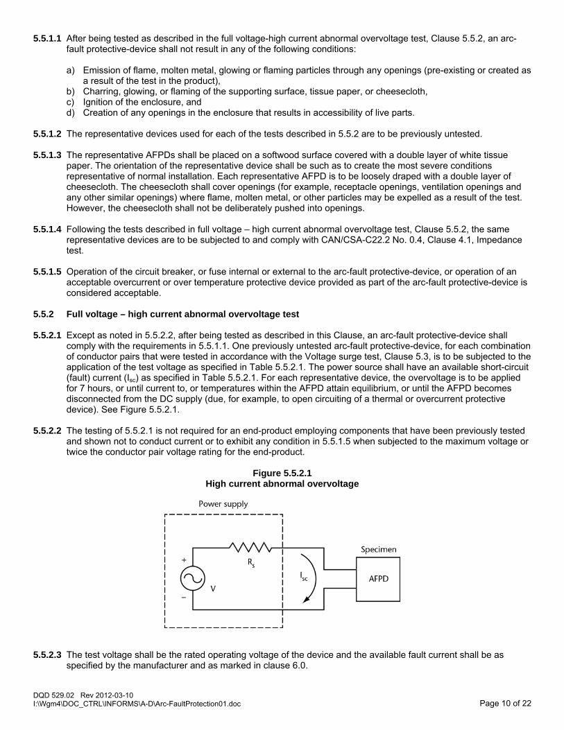
5.5.2 Full voltage – high current abnormal overvoltage test 5.5.2.1 Except as noted in 5.5.2.2, after being tested as described in this Clause, an arc-fault protective-device shall
comply with the requirements in 5.5.1.1. One previously untested arc-fault protective-device, for each combination of conductor pairs that were tested in accordance with the Voltage surge test, Clause 5.3, is to be subjected to the application of the test voltage as specified in Table 5.5.2.1. The power source shall have an available short-circuit (fault) current (Isc) as specified in Table 5.5.2.1. For each representative device, the overvoltage is to be applied for 7 hours, or until current to, or temperatures within the AFPD attain equilibrium, or until the AFPD becomes disconnected from the DC supply (due, for example, to open circuiting of a thermal or overcurrent protective device). See Figure 5.5.2.1.
5.5.2.2 The testing of 5.5.2.1 is not required for an end-product employing components that have been previously tested
and shown not to conduct current or to exhibit any condition in 5.5.1.5 when subjected to the maximum voltage or twice the conductor pair voltage rating for the end-product.
Figure 5.5.2.1
High current abnormal overvoltage
5.5.2.3 The test voltage shall be the rated operating voltage of the device and the available fault current shall be as
specified by the manufacturer and as marked in clause 6.0.

DQD 529.02 Rev 2012-03-10 Page 11 of 22 I:\Wgm4\DOC_CTRL\INFORMS\A-D\Arc-FaultProtection01.doc
5.5.2.4 Connection of the test circuit in series with a circuit breaker or time delay non-current limiting fuse rated for the maximum ampacity of the circuit in which the AFPD is to be installed, as specified in the Canadian Electrical Code, Part I, is permitted.
5.6 Arc-fault Detection Tests 5.6.1 General 5.6.1.1 In order to demonstrate that the DC-AFPD can detect and protect against arcing, a representative DC-AFPD of
each rating that has been subjected to the applicable preconditioning tests listed in Table 5.6.1.1, shall then be tested for each appropriate test series as defined in Table 5.1.2 and described in Clause 5.6.
Table 5.6.1.1 Pre-conditioning Tests
Test Ref. Clause
Humidity 5.2 Voltage Surge 5.3
Surge Current Test 5.4 Abnormal Overvoltage Test 5.5
5.6.1.2 The Series Connection Arcing Test of Clause 5.6.2 shall be conducted on all DC-AFPDs. The Parallel Path
Arcing Test of Clause 5.6.3 shall be conducted only on those devices that detect or interrupt parallel arcing faults.
5.6.1.3 The Arc-Fault Detection Tests shall be performed at 25°C ambient, except that the Series Connection Arc Test of Clause 5.6.2 shall be performed in a 66°C, -35°C and 25°C ambient following the sequence shown in Table 5.6.1.3.
Table 5.6.1.3
Test Sequence for Series Connection Arc Tests
Ambient air temperaturea Operating parameters Remarks
1. 25.0 ± 5.0° C No voltage applied Establish thermal equilibrium with at least two hours of exposure. Do not test.
2. 25.0 ± 2.0° C Rated voltage Test per Clause 5.5 as soon as possible to minimize self-heating.
3.b 66.0 ± 2.0° C Rated voltage and current Establish thermal equilibrium with at least two hours of exposure. Do not test.
4.b 66.0 ± 2.0° C Rated voltage Test per Clause 5.5.4.
5.c 40.0 ± 2.0° C Rated voltage and current Establish thermal equilibrium with at least two hours of exposure. Do not test.
6.c 40.0 ± 2.0° C Rated voltage Test per Clause 5.5.4.
7. 25.0 ± 5.0° C No voltage applied Establish thermal equilibrium with at least two hours of exposure. Do not test.
8. -35.0 ± 2.0° C No voltage applied Establish thermal equilibrium with at least two hours of exposure. Do not test.
9. -35.0 ± 2.0° C Rated voltage Test per Clause 5.5.4 as soon as possible to minimize self-heating.
10. 25.0 ± 5.0° C Rated voltage and current Establish thermal equilibrium with at least two hours of exposure. Do not test.
11. 25.0 ± 5.0° C Rated voltage Test per Clause 5.5.4.
a) The ambient air temperature is to be changed to each value shown without intentional delay. b) In the event that a DC-AFPD is self-protecting such that it trips at this ambient temperature, lower values of load
current are to be employed, until the device just continues to operate, if possible. c) This test is not to be performed if steps 3 and 4 have been performed employing rated current.
5.6.2 Series Connection Arcing Test (All devices)

DQD 529.02 Rev 2012-03-10 Page 12 of 22 I:\Wgm4\DOC_CTRL\INFORMS\A-D\Arc-FaultProtection01.doc
5.6.2.1 This test, which is required for all devices, shall be carried out as specified in the following steps:
a) Use an arc generator (see Figure 5.6.2.1) with one fixed and one stationary electrode, with the electrodes constructed as follows: 1) made of solid copper rod; 2) the stationary electrode measures approximately 6 mm in diameter; 3) the adjustable electrode has a stem measuring approximately 6 mm in diameter with a plastic sleeve
extension attached to the end; and 4) both electrodes have provision for screw mounting electrical conductors.
b) As indicated in Figure 5.6.2.1, place a small amount of very fine steel wool, such as Size 00, into the pan. There shall be enough to link the final gap between the electrodes and trigger the arc when voltage is applied. Adjust the gap between electrodes to the suitable distance.
c) Connect the device under test (the "device") and arc generator to a PV power source in order to attain the necessary arc voltage and current. The power source shall be either: 1) a PV power source having PV modules linked in series or in series/parallel array; or 2) a simulated PV DC power source with characteristics similar to that of the PV array. Do not use an inverter or charge controller.
Note: To limit the test current to the necessary value, a ballasting resistor may be used in the circuit. Note: To reach the necessary arc voltage, the electrode gap may be adjusted. As indicated in Figure 5.6.2.2, connect the arc generator in series with the device and, with the electrode gap set to the desired separation, apply the PV power to the device. Note: For the purpose of this evaluation, testing conducted to UL 1699B, Section 23 and using the test fixture identified in Figure 23.1, shall be considered as equivalent.
5.6.2.2 The total arcing time before the device detects or interrupts arcing shall not exceed the lesser of the following:
a) 2 s; or b) X seconds
where: X = 750 Joules/[A x V] A = measured arcing current, Amps V = measured arcing voltage, Volts
5.6.2.3 Testing shall be repeated three times at the voltage and current levels specified in Table 5.6.2.3. For devices with circuit interruption, the device shall be closed on the fault and allowed to open the circuit or detect arcing. As indicated in Figure 5.6.2.3, for all devices, the test shall be repeated with switch S1 closed on the load side of the device under test. The current level specified in Table 5.6.2.3 shall be calibrated with Si and S2 closed. The test shall be conducted with S2 open.

DQD 529.02 Rev 2012-03-10 Page 13 of 22 I:\Wgm4\DOC_CTRL\INFORMS\A-D\Arc-FaultProtection01.doc
Figure 5.6.2.1 (revised)
Arc Generator

DQD 529.02 Rev 2012-03-10 Page 14 of 22 I:\Wgm4\DOC_CTRL\INFORMS\A-D\Arc-FaultProtection01.doc
Figure 5.6.2.3 (Revised) Series connection arcing test circuit
Table 5.6.2.3 Arcing tests and clearing times
Arcing current (amps)a, d
Arcing voltageb (volts)
Arcing Wattsa (typical)
Approximate electrode, mmb Max time (sec)c
7 43 300 1.6 2 7 71 500 4.8 1.5 14 46 650 3.2 1.2 14 64 900 6.4 0.8
a) Arcing current shall be ±20% and arcing Watts (typical) shall be ±10% b) The arcing voltage may be any value required to achieve arcing Watts. Electrode gap may be adjusted to achieve needed
arcing voltage. c) Based on average Watts. See Clause 5.6.2.3 for actual maximum detection or interruption times. d) For devices rated less than arcing current, the test current may be reduced to the rated current and arcing Watts required.
5.6.3 Parallel Path Arcing Test (Parallel Arcing Detection Devices only) 5.6.3.1 This test, which is required for parallel arcing detection devices only, shall be carried out as specified in the
following steps:
a) Use the arc generator specified in 5.6.2.1 or equivalent fixture. b) To attain the necessary arc voltage and current, connect the device under test (the "device") and the arc
generator to a PV power source, e.g., PV modules connected in series or in series/parallel array. For load, use an inverter, converter, or charge controller.
c) As indicated in Figure 5.6.3.1, switch S2 and the arc generator are placed: 1) on the load side of the device; and 2) in a parallel path between the positive and negative conductors of the PV power source.
With the electrode gap at the required separation, apply the PV power to the device.
5.6.3.2 The total arcing time before the device detects or interrupts arcing shall not exceed the lesser of the following:
a) 2 s; or b) seconds = 750 Joules/[A x V]

DQD 529.02 Rev 2012-03-10 Page 15 of 22 I:\Wgm4\DOC_CTRL\INFORMS\A-D\Arc-FaultProtection01.doc
where A = measured arcing current, amps V = measured arcing voltage, volts
Figure 5.6.3.1 Parallel path arcing test circuit
5.6.3.3 Testing shall be repeated three times at the voltage and current levels specified in Table 5.6.2.2. As indicated in Figure 5.6.3.1, the test shall be conducted with switch S2 closed in the parallel path on the load side of the device.
The current level specified in Table 5.6.2.3 shall be calibrated with Si, S2 and S3 closed. The test shall be conducted with S3 open.
5.7 Unwanted Tripping Tests 5.7.1 Loading Condition I – Inverters, Converters, and Charge Controllers 5.7.2.1 Loading condition I shall consist of the individual loads, as follows:
a) single-phase inverter; b) three-phase inverter; c) converter; and d) charge controller.
5.7.2.2 The test shall be conducted as follows:
a) Install the device under test (the "device") 0.6 m from the inverter, converter, or charge controller. b) Using a PV power source at rated voltage and current of the device, turn on the inverter, converter, or charge
controller for at least 5 min and then turn "off" for at least 5 min. c) For each load, repeat the sequence in Item (b) 3 times.
5.7.2 Loading Condition II – DC Switch Operation The test shall be conducted as follows:
a) Install the device under test (the "device") in a test circuit with a PV power source and an inverter. b) Install a disconnect switch 0.6 m from the device.

DQD 529.02 Rev 2012-03-10 Page 16 of 22 I:\Wgm4\DOC_CTRL\INFORMS\A-D\Arc-FaultProtection01.doc
c) Turn on the disconnect switch with the PV power source operating at rated voltage and current of the device and, after 30 s, turn off the disconnect switch.
d) Repeat the sequence in Item (c) 3 times, with the inverter turned off for 5 min between each "off" and "on" sequence.
5.7.3 Result After a representative device of each rating is tested at the loading and sourcing conditions specified in Clauses
5.7.1 and 5.7.2, tripping shall not occur. If there is tripping, an additional five representative devices of each rating shall be tested as in Clauses 5.7.1 and 5.7.2. Tripping shall not occur on any of those five samples.
5.8 Operation Inhibition Tests 5.8.1 This test shall be conducted using the apparatus specified in Clause 5.6.2. 5.8.2 Inhibiting the signal 5.8.2.1 The device under test shall be tested with each of the following load conditions using the arc test in accordance
with Section 5.6.2. The arc generating fixture shall have a switch S2 added in parallel as shown in Figures 5.8.1 and 5.8.2, in order to bypass the arc generator and allow the inverter to achieve a proper "on" state before the arc fault test is started by opening the switch. The device shall interrupt or detect the arcing as specified in Table 5.6.2.3 for the conditions of 300 and 900 Watts.
5.8.2.2 The test shall be conducted as follows:
a) Install the device in a test circuit with a PV power source and an inverter, as indicated in Figure 5.8.1. b) Install the device in a test circuit with a PV power source and an inverter, as indicated in Figure 5.8.2.
Conduct the test with PV string 1, while PV string 2 is combined with PV string 1. PV string 2 shall have the same power as PV string 1.
Figure 5.8.1 Inhibition Test with Arcing and Inverter
Figure 5.8.2 Inhibition Test with Arcing and Multiple Strings

DQD 529.02 Rev 2012-03-10 Page 17 of 22 I:\Wgm4\DOC_CTRL\INFORMS\A-D\Arc-FaultProtection01.doc
5.8.3 Inhibition test with Line impedance 5.8.3.1 The test shall be as follows:
a) Conduct the test as described in Clause 5.6.2 with the exception that a length of conductor shall be placed between the device under test (the "test") and the switch S1.
b) As indicated in Figure 5.8.3, the length of wire shall be 60 +- 2 m in length and arranged with four to six 180° bends of six inch radius.
5.8.3.2 The device shall interrupt or detect the arcing as specified in Table 5.6.2.3 for the conditions of 300 and 900
Watts.
Figure 5.8.3 Inhibition Test with Line Impedance

DQD 529.02 Rev 2012-03-10 Page 18 of 22 I:\Wgm4\DOC_CTRL\INFORMS\A-D\Arc-FaultProtection01.doc
5.9 Dielectric Voltage-Withstand Test
A dielectric voltage-withstand test shall be conducted as follows: a) A DC-AFPD shall be capable of withstanding for 1 min without breakdown the application of an ac voltage of
1000 V rms (or DC equivalent) plus twice maximum rated voltage, except that where the circuit potential does not exceed 70 V in normal service, the test potential shall be 500 V:
1) between line and load; 2) between live parts and exposed non-current-carrying metal parts; 3) between live parts and parts of isolated circuits; and 4) between live parts and accessible non-metallic (insulating) surfaces.
b) Where the construction of the device is such as to deny access to the parts to be tested, suitable
subassemblies may be employed. c) Metal foil shall be used in the application of test potentials to insulating surfaces and care shall be taken to
avoid flashover at the edge of the insulation. 5.10 Immunity to conducted disturbances, induced by RF fields
The AFPD shall operate normally (test and reset) after completion of this test and there shall not be any evidence of a risk of fire or risk of electrical shock. The AFPD shall not trip when subjected to the applied frequency. The test method described in the Standard for Electromagnetic Compatibility (EMC) Part 4: Testing and Measurement Techniques – Clause 6, Immunity to conducted disturbances, induced by radio-frequency fields, of IEC 61000-4-6, is to be followed. The representative AFPD is to be subjected to a conducted disturbance at 0.5 V over a frequency range of 150 kHz to 230 MHz.
5.11 Normal Temperature Test
A normal temperature test shall be conducted as follows: a) When carrying rated current and with rated voltage applied, a device shall not attain a temperature at any
point that is sufficiently high to: 1) constitute an increased risk of fire; 2) affect injuriously any materials used in the device; or 3) exhibit rises in temperature at specific points greater than indicated in Table 5.11. The temperature rises
specified in Table 5.11 are based on an ambient temperature of 25° C and apply to equipment intended for use in ambient temperatures normally prevailing in occupied spaces which usually are not higher than 25° C but may be as high as 40° C occasionally and for brief periods. Tests of equipment for service with such ambient temperatures may be conducted (without correction) at any ambient temperature between 10 and 40° C. If equipment is intended specifically for use in a prevailing ambient temperature constantly more than 25° C, the test of the equipment shall be made with that higher ambient temperature, and the allowable temperature rises specified in Table 5.11 shall be reduced by the amount by which the higher ambient exceeds 25° C.
b) Coil or winding temperatures shall be measured by the rise of resistance method. At a point on the surface of a coil where the temperature is affected by an external source of heat, the temperature rise measured by means of a thermocouple may be 10°C more than the indicated maximum, provided that the temperature rise of the coil, as measured by the rise of resistance method, is no more than that specified in Table 5.11.
c) Except at coils, temperature readings shall be obtained by means of thermocouples, and a temperature shall be considered to be constant when three successive readings, taken at intervals of 10% of the previously elapsed duration of the test, but not less than 5 min intervals, indicate no change.
d) Ambient air shall be at any convenient temperature within the range of 20° to 30° C. e) A representative DC-AFPD shall also meet the applicable temperature requirements of CSA Standard C22.2
No. 5.

DQD 529.02 Rev 2012-03-10 Page 19 of 22 I:\Wgm4\DOC_CTRL\INFORMS\A-D\Arc-FaultProtection01.doc
Table 5.11 Maximum acceptable temperature rises
Material and components °C
Wire insulation or insulating tubing 35 Electrical tape 55 Varnish cloth insulation 60 Fibre employed as electrical insulation 65 Phenolic composition or melaminea 125 Urea compositiona 75 Other insulating materialsa - a) The acceptability of insulating materials shall be determined with respect to properties –
such as flammability, arc resistance, relative or generic temperature indices, and the like - based on the temperature rise plus 25°C.
5.12 Overvoltage Test
A device shall operate continuously while connected to a supply set at 110% of rated voltage. The test shall continue for 4 h or until thermal equilibrium is reached and shall not trip. There shall be no damage to the DC-AFPD. Immediately following the test, the "Test" circuit shall be operated and the device shall trip.
5.13 Overload
The overload test shall be conducted as described in items (a) to (d):
a) As a result of the tests of clause 5.13, items (b) to (d) there shall be no electrical or mechanical breakdown of the device nor any undue burning, pitting, or welding of the contacts, and the fuse specified in Item (c) shall not open.
b) A DC-AFPD shall switch a DC load adjusted for a value of load current equal to 2 times the ampere rating of the device at rated voltage.
c) The supply circuit for the test mentioned in Item (b) shall have the capacity to provide a closed-circuit voltage of not less than 85% of the rated voltage of the device. Except when a higher value is agreed to by those concerned, the open-circuit voltage shall be in the range of 100 to 105% of the rated voltage of the device. A 1 A Class H fuse shall be connected between the grounded conductor of a grounded supply circuit and accessible conductive parts of the device. This fuse shall not operate to open the circuit.
d) In performing the test described in Item (b), the device shall be switched ON and, after not less than one cycle, switched OFF, for a total of 50 cycles of operation, at the rate of 6 cycles per minute.
Note: If the device operation will not permit these cycle times, times as close as possible to the cycle times shall be used. 5.14 Endurance Test
An endurance test shall be conducted as described in items (a) to (d): a) As a result of the tests of clause 5.14, items (b) to (d) there shall be no electrical or mechanical breakdown of
the device nor any undue burning, pitting, or welding of the contacts and the fuse specified in Item (d) shall not open.
b) In order to determine compliance with Item (a), a device shall be caused to switch a DC load adjusted for a value of load current equal to the ampere rating of the device.
c) In performing the test described in Item (b), the device shall be switched ON and, after 1 s, switched OFF at a rate of approximately 6 cycles of operation per minute for 3000 cycles and switched ON and, after 1 s "tripped" OFF by using the test switch for 3000 cycles. Ten percent of the latter 3000 operations shall be performed with the supply voltage reduced to 85% of the rated voltage.
Note: The initial 3000 cycles are not required when the device under test has no ON/OFF switch.
Note: The endurance test of CSA Standards C22.2 No. 5 and 144.1 are performed on different samples.

DQD 529.02 Rev 2012-03-10 Page 20 of 22 I:\Wgm4\DOC_CTRL\INFORMS\A-D\Arc-FaultProtection01.doc
d) In performing the test described in Item (b), the capacity of the supply circuit shall be such as to allow a
closed-circuit voltage not less than 97.5% of the rated voltage of the device. Except when a higher value is agreed to by those concerned, the open-circuit voltage shall be in the range of 100 to 105% of the rated voltage of the DC-AFPD. A 1 A Class H fuse shall be connected between the grounded conductor of a grounded supply circuit and accessible conductive parts of the device. This fuse shall not operate to open the circuit.
5.15 Abnormal Operations Test An abnormal operations test shall be conducted as follows:
a) The DC-AFPD design shall be examined to determine component failure modes that could result in the risk of shock or fire hazard. The DC-AFPD or a representative subassembly, where necessary, shall be operated at rated conditions and the appropriate faults simulated. The device under test shall be operated until the circuit opens or until temperatures stabilize. The tests shall be permitted to be performed on separate samples or on a single sample if it is determined that the results of a test will not be affected by the previous test.
b) A single layer of cheesecloth shall be loosely draped over the surface of the device. A 1 A Class H fuse shall be connected between the grounded supply conductor and accessible conductive parts of the device.
c) cheesecloth mentioned in Item (b) shall be bleached cheesecloth running 14 to 15 square yards per pound mass (approximately 26 to 28 m2 per kilogram mass) and having what is known in the trade as a "count of 32 by 28”, that is, for any square inch, 32 threads in one direction and 28 threads in the other direction (for any square centimetre, 13 threads in one direction and 11 in the other direction).
d) A device operating under abnormal conditions will be considered to have become a risk of injury if: 1) there is glowing or flaming of the cheesecloth or tissue paper mentioned in Item (b); 2) there is emission of molten metal; 3) the fuse mentioned in Item (b) operates to open the circuit; 4) It is possible to touch a part with the articulated probe shown in Figure 14 while there is a risk of shock at
that part (Not applicable to tests of sub-assemblies); 5) there is dielectric failure; or 6) There is any other evidence of a risk of injury.
5.16 Short Circuit Current Test
A short circuit current test shall be conducted as follows: a) A DC-AFPD shall comply with the short circuit test as described in clause 5.16, except that a DC-AFPD
meeting the short circuit test requirements of CSA Standard C22.2 No. 5 shall not be required to be tested. b) The supply circuit shall have an open-circuit voltage in the range of 100 to 105% of the rating of the device.
The impedance of the supply shall be such as to provide a prospective current as per the manufacturer name plate rating.
c) Each line terminal of a device shall be connected to the supply mentioned in Item (b) using 1.2 m of insulated wire, sized for the rating of the device. An overcurrent protective device with an ampere and interrupting rating equal to the appropriate overcurrent protection shall be connected in series with the ungrounded line conductor or conductors. A 508 mm conductor shall be connected between the load terminals. The DC-AFPD shall be in any position considered to be normal service. A 1 A Class H fuse shall be connected between the supply terminal representing the grounded circuit conductor and accessible conductive parts of the device. Surgical cotton shall cover openings of the device where flame may be emitted. (See Figure 5.16).
d) The prospective current shall be initiated once by means of a switch in the supply circuit, and once by means of the DC-AFPD contacts. The tests shall be repeated after reversing the line and load connections to the device.
e) It shall be permitted to use separate samples for each of the tests described in item (d). f) There shall be no electrical or mechanical failure of the device, no damage to the insulation on conductors, no
ignition of the cotton, and the fuse shall not open during the above test. g) Immediately after the short circuit test the sample DC-AFPD shall comply with the dielectric strength test of
clause 5.9.

DQD 529.02 Rev 2012-03-10 Page 21 of 22 I:\Wgm4\DOC_CTRL\INFORMS\A-D\Arc-FaultProtection01.doc
Figure 5.16 Short Circuit Test
5.17 Terminal Lead Strain-Relief Test 5.17.1 A device that is provided with terminal leads intended to be connected in the field shall be subjected to the test
described in clause 5.17.2. 5.17.2 The leads shall be disconnected from the internal point of termination. Each terminal lead shall be subjected to a
tensile force increased gradually to 89 N, and maintained at that value for 5 min. 5.17.3 The test results shall be considered to be acceptable if the force is not transmitted to the terminations and there is
no indication that either the device or the lead has sustained damage. 5.18 Mechanical Tests 5.18.1 An interrupting device that is provided with pressure wire connectors or wire binding screw terminals intended for
field wiring shall be subjected to the tests described in clauses 5.18.2 and 5.18.3. 5.18.2 There shall be no breakage or damage of any part of the device when 110 percent of the marked terminal
tightening torque is applied to the wire securing means of a pressure wire connector. 5.18.3 A wire binding screw or nut shall be tightened on a conductor selected in accordance with the ampere rating of
the device, but no less than 14 AWG (2.1 mm2), to a torque of 2.3 N.m without causing displacement of the wire or damage to the terminal assembly or the wire. Except where the configuration of the terminal assembly does not permit, or markings allow, the use of unformed wire, the wire is to be formed into a 3/4 loop that will just be accommodated by the assembly, before tightening.
5.19 Corrosion Test
5.19.1 An arc-fault protective-device shall operate as intended after being subjected to the corrosive atmosphere test described in 5.19.2 and 5.19.3. The representative AFPD is to be tested for trip threshold prior to exposure to the corrosive atmosphere.
5.19.2 One representative AFPD is to be placed in a 200 liter or larger test chamber on a platform approximately 50 mm
above the bottom of the chamber. The temperature in the chamber is to be maintained at 30 ±2°C and the relative humidity at 70 ±2 percent (measured directly in the chamber). The temperature and humidity are to be checked daily. Because of the corrosive atmosphere a set of wet and dry bulb thermometers shall be used for measurement of relative humidity.
5.19.3 The following gas mixture in air is to be supplied to the chamber at a rate sufficient to achieve an air exchange in
the chamber of about five times per hour, for a period of 3 weeks: 100 ±10 parts per billion (ppb) (parts per billion = parts per 109 by volume) hydrogen sulfide (H2S) plus 20 ±5 ppb chlorine (Cl2) plus 200 ±50 ppb nitrogen dioxide (NO2). The air inside the chamber is to be circulated by a single fan, with flow upwards from the bottom. See 5.19.4.

DQD 529.02 Rev 2012-03-10 Page 22 of 22 I:\Wgm4\DOC_CTRL\INFORMS\A-D\Arc-FaultProtection01.doc
5.19.4 Trip threshold measurements following the exposure to the corrosive atmosphere shall not cause false tripping and shall comply with the trip threshold requirements of this T.I.L. The trip threshold levels are to be measured in accordance with the Unwanted Tripping Test, Clause 5.7, giving consideration to the most adverse conditions. The measurements are to be performed at room temperature.
6.0 MARKING DC-AFPD’s shall be plainly marked in a permanent manner with at least the following:
a) manufacturer’s name, trademark, trade name, or other recognized symbol of identification; b) catalogue or type designation; c) rated current (A) d) voltage (V); e) test and reset button are identified; f) “Photovoltaic DC -ARC-FAULT circuit interrupter”, or “Photovoltaic DC-arc fault detector (DC-AFD), or
“Photovoltaic DC interrupting device” Note: abbreviated forms of the above defined terms may be used. g) DC-AFPD’s shall be marked with the applicable markings from, CAN/CSA-C22.2 No. 144.1, CSA C22.2 No.
5. h) Short circuit current rating. i) “Suitable for series arcing fault protection only” (may also be designated as Type 1) or “suitable for series and
parallel arcing fault protection (May also be designated as Type 2).


![ge...Arcing is the microwave term fl)r sparks in the oven. Arcing is caused by: [] Metal or foil touching the side of the oven. [] [] Foil not molded to food (upturned edges act like](https://static.fdocuments.us/doc/165x107/5eca3b2dce74ca60fc41c234/ge-arcing-is-the-microwave-term-flr-sparks-in-the-oven-arcing-is-caused-by.jpg)