An RESUME - Transactions of the Canadian Society for ... · acoustique-structure est un sujet...
24
ANALYTICAL MODEL OF SOUND TRANSMISSION THROUGH ORTHOTROPIC DOUBLE WALLED CYLINDERICAL SHELLS K. Daneshjou, R. Talebitooti, A. Nouri Department of Mechanical Engineering, Iran University of Science and Technology, Tehran, Iran Contact: [email protected] Received March 2007, Accepted March 2008 No. 07-CSME-14, E.LC. Accession 2983 ABSTRACT Due to the high levels of noise into the modem launchers, the structural-acoustic coupling problem is an important subject in the area of vibro-acoustic analysis. In this paper, analytical study is conducted on oblique plane wave incident upon a flexible orthotropic double-walled thin cylindrical shell to understand the characteristic of sound transmission. External and internal fluid media surround the shells and there is fluid (air) in the annular space between them. A uniform flow moves with a constant velocity in the external fluid medium. The wave equations represent the fluid media and the Sanders equations describe the motions of the two shells. On the internal and external shell surfaces, the equations of fluid-structure interaction are considered. An exact solution is obtained by solving the classical shell equations and acoustic wave equations simultaneously. As, the pressure and displacement terms are expressed in infinite series form, an iterative procedure is constructed in each frequency. This convergence algorithm presents the advantage of best accuracy. Transmission losses (TLs) obtained from numerical solution are compared with those of other authors. Eventually, the numerical results are used to show the effects of, orthotropy ratio, geometrical properties, air gap specifications, Mach number, material and fluid properties. UN MODELE ANALYTIQUE POUR LA TRANSMISSION DES ONDES ACOUSTIQUES PAR LES DOUBLE PAROIS ORTHOTROPIQUES CYLINDRIQUES RESUME En raison du haut niveau de bruit produit par les lanceurs modernes, Ie probleme de couplage acoustique-structure est un sujet important dans les etudes vibro-acoustique. Dans cette etude avec une approche analytique, les caracteristiques des ondes acoustiques reflechissant d'une double paroi flexible orthotropique cylindrique ont ete etudies. Sur les surfaces externes et interieures, les equations de fluide-structure ont ete resolues. La solution exacte est obtenue par la solution simultanement des equations de paroi et de l' onde acoustique. Comme la pression et les termes de deplacement sont exprimes dans la forme de serie infinie, une procedure iterative est construite dans chaque frequence. Les pertes de transmission (TLs) obtenues de la solution numerique sont comparees avec ceux d'autres auteurs. Finalement, les resultats numeriques sont utilises pour montrer les effets de rapport orthotropique, proprietes geometriques, les specifications de les pace entre parois, Ie nombre de Mach, les proprietes de materielle et de liquide. Transactions ofthe CSME Ide fa SCGM Vol. 32, No.1, 2008 43
Transcript of An RESUME - Transactions of the Canadian Society for ... · acoustique-structure est un sujet...

ANALYTICAL MODEL OF SOUND TRANSMISSION THROUGH ORTHOTROPICDOUBLE WALLED CYLINDERICAL SHELLS
K. Daneshjou, R. Talebitooti, A. NouriDepartment of Mechanical Engineering, Iran University of Science and Technology,
Tehran, IranContact: [email protected]
Received March 2007, Accepted March 2008No. 07-CSME-14, E.LC. Accession 2983
ABSTRACTDue to the high levels of noise into the modem launchers, the structural-acoustic coupling
problem is an important subject in the area of vibro-acoustic analysis. In this paper, analyticalstudy is conducted on oblique plane wave incident upon a flexible orthotropic double-walled thincylindrical shell to understand the characteristic of sound transmission. External and internalfluid media surround the shells and there is fluid (air) in the annular space between them. Auniform flow moves with a constant velocity in the external fluid medium. The wave equationsrepresent the fluid media and the Sanders equations describe the motions of the two shells. Onthe internal and external shell surfaces, the equations of fluid-structure interaction areconsidered. An exact solution is obtained by solving the classical shell equations and acousticwave equations simultaneously. As, the pressure and displacement terms are expressed in infiniteseries form, an iterative procedure is constructed in each frequency. This convergence algorithmpresents the advantage of best accuracy. Transmission losses (TLs) obtained from numericalsolution are compared with those of other authors. Eventually, the numerical results are used toshow the effects of, orthotropy ratio, geometrical properties, air gap specifications, Machnumber, material and fluid properties.
UN MODELE ANALYTIQUE POUR LA TRANSMISSION DES ONDESACOUSTIQUES PAR LES DOUBLE PAROIS ORTHOTROPIQUES CYLINDRIQUES
RESUMEEn raison du haut niveau de bruit produit par les lanceurs modernes, Ie probleme de couplage
acoustique-structure est un sujet important dans les etudes vibro-acoustique. Dans cette etudeavec une approche analytique, les caracteristiques des ondes acoustiques reflechissant d'unedouble paroi flexible orthotropique cylindrique ont ete etudies. Sur les surfaces externes etinterieures, les equations de fluide-structure ont ete resolues. La solution exacte est obtenue parla solution simultanement des equations de paroi et de l'onde acoustique. Comme la pression etles termes de deplacement sont exprimes dans la forme de serie infinie, une procedure iterativeest construite dans chaque frequence. Les pertes de transmission (TLs) obtenues de la solutionnumerique sont comparees avec ceux d'autres auteurs. Finalement, les resultats numeriques sontutilises pour montrer les effets de rapport orthotropique, proprietes geometriques, lesspecifications de les pace entre parois, Ie nombre de Mach, les proprietes de materielle et deliquide.
Transactions ofthe CSME Ide fa SCGM Vol. 32, No.1, 2008 43

1. Introduction
Initially limited to the transmission of airborne noise into an aircraft fuselage, noise transmission-relatedproblems have received significant attention, particularly since noise levels in modem launchers exceedacceptable safety criteria payloads. A cylindrical shell is an important basic structural element widelyused in the aerospace industry. The reduction of noise transmitted into such structures is particularlychallenging due to the high excitation levels, the complex nature of the disturbance, and the severe massand volume constraints imposed on the design of the treatments. However, the structural-acousticcoupling problem for this kind of shell has still been an important subject in the area of vibro-acousticanalysis up to now.
The most advanced noise transmission analyses were briefly reviewed by Dowell [1] with respect to allflight vehicles. Smith [2] presented a theoretical study of transmission of sound energy through a thin,isotropic elastic cylindrical shell from an oblique plane wave excitation. To some extent, Koval [3-5]extended Smith's results to different kinds of shells. He systematically introduced internal pressurization,orthotropic and composite shells into his analysis. Blaise et al. [6] then extended Koval's work to consideran orthotropic shell excited by an oblique plane sound wave with two independent incident angles. Tanget al. [7] considered an infinite cylindrical sandwich shell excited by an oblique plane sound wave withtwo independent incident angles. Analytical and experimental studies are conducted by Kim & Lee [8] tounderstand the characteristics of sound transmission through the infinitely long circular cylindrical shell.The authors have recently studied analytical model of sound transmissions through laminated compositecylindrical shells [9]. In this model, Parameters were varied to see how laminate specification could affectnoise transmission.
In most of analytical studies surveyed above, a simplified shell theory, typically bending approximationsor Donnel-Mushtari equations, were used to model the shell motion. In addition, in most of them, theequation of motion in the transverse direction was used to describe the shell motion and in-planeequations were completely neglected, which may not be valid in general. In some cases, numbers of termsused in the series solution were apparently insufficient to provide converged solutions, which could haveaffected the very large TLs estimated results. During the past decades, sound transmission through doublewalls separated by an air gap has been investigated by many researchers [10-18] since the constructionwill produce both noise attenuation and thermal insulation. These investigations have shown that doublewalls can increase transmission loss over a single wall. Among these studies, most of them assumed thedouble walls are flat with absorbent materials. Only a few focused on the study of double walls consistingof two concentric cylindrical shells. However, these investigations are mostly limited to the study of twoisotropic shells or using finite element method for composite double walled cylinders.
The objective of this paper is to calculate TLs of infinite orthotropic double-walled cylindrical shell witheffect of external airflow. Since, classical shell theory is applicable when the thickness is smaller than(l/20)th of the smallest of the wave lengths and/or radii of curvature [19], an exact solution was obtainedin a series form using Sanders equations, the classical shell vibration equations, without ignoring any ofthree directions of the shell. The shell is assumed to be immersed in a fluid media and excited by anincident oblique plane sound wave. Acoustic wave equations and shell equations, which are coupled withone another, are solved simultaneously. To make sure an enough number of modes are included in theanalysis, the convergence checking is performed. Finally, the numerical results are used to show theeffects of air gap specifications, Orthotropy ratio, geometrical properties, Mach number, material andfluid properties.
Transactions ofthe CSME Ide la SCGM Vol. 32, No. I, 2008 44

2. Model Specification
The specific problem studied is that of an oblique plane wave incident upon a flexible orthotropic doublewalled thin cylindrical shell (see Fig. 1) which is typical in many studies [7,8]. A plane wave is incidentwith an angle YJ (measured from the axis of cylinder) from outside to an infinite cylinder whose interior
of the shell is assumed to be entirely absorbing so that only inward-propagating waves is assumed toexist. The incident wave is a plane wave whose rays are traveling on plane parallel to the x-z plane (i.e. itapproaches from the e= 7t direction). In the analysis, all waves will be assumed to have the samedependence on the axial co-ordinate z. There is a uniform airflow at velocity V in the external fluidmedium. Rl'R Z,h] and h z indicate the radii and thickness of the shells, in which the subscripts 1 and 2
represent the inner and outer shells, respectively. The fluid media in the external, in-between, and theinternal space are defined by the density and the speed of sound: {Pl'cJ, {pz,czland
{P3' c3}respectively. properties of the shells are defined by the density, young's modulus, and the
Poisson ratio: ,,~, E], v] }, ,,~ ,Ez,V z}.
3. Vibro-acoustic Equations
Due to the existence of airflow the external pressure, which is the summation of the incident wave p I and
the reflected wave p~ , satisfies the acoustic wave equation [20]:
(1)
where V is the gradient operator in the cylindrical coordinate system.
In the annular space between the shells, the pressure is pz = p; + p~ , where p; is the transmitted wave
through the external shell, and p ~ is the reflected wave from the internal shell, which satisfies the
acoustic wave equation.
(2)
In the internal cavity, the acoustic pressure of the transmitted wave p~ satisfies the acoustic wave
equation:
Transactions ofthe CSME Ide la SCGM Vol. 32, No.1, 2008
(3)
45

y
Inn~r ShellAir Gap
Outer Shell
Fig. 1. Schematic diagram of the double-walled cylindrical shell.
Let{u~ , v~ , w~}, i=1,2, be the displacements of the shell at the neutral surface in the axial,
circumferential, and radial directions respectively, where the subscripts 1 and 2 denote the variablesassociated with the inner shell and the outer shell. Sanders equations can be used to describe the motionsof the two shells [21, 22]. Equations of motion in the axial, radial and circumferential directions of theinner and outer shells are:
[LO-M + K j LMod,sanders ]{u~ , v~ ,w~ }= g, i=1,2
where
(4)
Transactions ofthe CSME /de la SCGM Vol. 32, No. 1,2008 46

[au a12 an][LD_M]= a 21 a 22 a 23 (5)
a 31 a 32 a 33
[bU b 12 bn][LMOD_sanders]= b 21 b 22 b 23 (6)
b 31 b 32 b 33
g={o, 0, [(PT +p')_ pT]X (1-V~)R~} i=l For inner shell (7)2 2 3 E.h. '
1 1
g~{o, 0, [(P' +p,' )- (p,T +p,' )]x (1-E~~:R~}, i ~2For outer shell (8)
The elements of these matrices for the inner and outer shells, according to [23,24] can be followed as:
(9)
C(i) 02 C(i) (C(i) + C(i) ) 0 2 C(i) 0 2
a = a =----.!i.. __+~ 12 66 __+~ __12 21 C(i) OS2 C(i) C(i) osoe C(i) oe2
22 22 22 22
C(i) 0 C(i) 0=_12_+~_
a 13 = a 31 C(i) OS C(i) oe22 22
(10)
(11)
(12)
(13)
(14)
(15)
(16)
Transactions ofthe CSME Ide fa SCGM Vol. 32, No.1, 2008 47

- 3 D(i) 02 1 D(i) 02
b =b =-~----~--12 21 4 D(i) as 00 2 D(i) 002
22 22
(17)
(18)
(19)
- 3 D(i) 03 (D(i) + 3D(i) ) 03
b =b =- _1_6 __ 12 6623 32 2 D(i) as 3 D(i) as2 00
22 22
z K.--~s=-R.' I 12R~
I ,
(20)
(21)
Again, it should be noted that the subscripts 1 and 2 denote the variables associated with the inner shelland the outer shell. The coupling effect between the shell and the acoustic medium is represented by thepressure terms in the shell equation [Eq. (7, 8)].
4- Boundary conditions
On the internal and external shell surfaces, the particle velocities of the acoustic media in the normaldirection have to be equal to the normal velocity of the shell [8]. These results are shown in the followingequations [25].
(22)
(23)
(24)
Op~
or02 Wo_ P 1
-- 3 oer=R,
(25)
These equations, which represent the coupling in the fluid-solid interface, are referred as Euler'sequations.
Transactions ofthe CSME Ide la SCGM Vol. 32, No.1, 2008 48

5- Solution Procedure
The incidence plane wave can be represented by
pI = Po exp[j(rot - k 1x X - k1Zz)]
where Po is the amplitude of the incident wave and
(26)
(27)
where k 1 is the wave number in the moving medium. This incidence wave propagates in the moving
medium according to the wave equation
(28)
Substitution of equation (26) into equation (28) yields
where, M I = (V/ CI) is the Mach number of the external flow.
Using the relation between the cartesian and cylindrical coordinates (x = f cos e), Eq. (26) yields:
pI = Po exp[j(rot - k1Zz) - jkIrfcos9]
(29)
(30)
where k lr = k Ix .Using the mathematical relation between the exponential, the trigonometric and Bessel
function, the exponential term in equation (30) can be also written as [26]:
00
exp[-jkl,fcos8] = rEn (_j)n I n(k1,f)cos[n8]n=O
where En is the Neumann factor given by
(31)
Transactions ofthe CSME /de La SCGM Vol. 32, No.1, 2008 49
E ={In 2
n=On ~l
(32)
In addition, Jnis the Bessel function of the first kind of integer order n. Therefore, an incident oblique
plane wave pI (Fig. 1) can be expressed as the product of an axial traveling wave and an infmite sum of
cylindrical waves [3]:
pI (r,z, 9, t) = Po fEn (-jt Jn(k\rr)cos[n9] exp[j(rot - k1Zz)]n=O
(33)
where j =~ , n=O, 1, 2, 3 ... and l1J is the angular frequency.
Because the traveling waves in the acoustic media and inside the shell are driven by the incident-travelingwave, the wave numbers (or trace velocities) in the z direction should match throughout the system,
thereforek 3z =k 2z =k\z. Considering the Eqs. (27) and (29), the wave numbers in the external, middle
and internal media can be written as:
(34)
k2=~' k2z =k!Z' k2r=~k;-k;z=(~)1-(C2/cJ2cOS2Y)(1+MICOSYJ2]Yz (35)
k, =:" k" =k,,, k" =~k: - k:, =(:,}-(e,/e,)' cos' y.I(1 + M, cosy,)']!' (36)
The waves radiated from the shell to the outside and into the cavity,pf ,p~, p; andp~, can be
represented as:
pf(r,z,9, t) = fp~ H~ (k1rr)cos[n9]expu(rot -k\zz)]n=O
p; (r, z, 9, t) = fP;n H~ (k2rr)cos[n9] expu(rot - k\zz)]n=O
p~ (r,z,9, t) = fP~n H~ (k 2r r) cos[n9] expu(rot - k\zz)]n=O
(37)
(38)
(39)
Transactions ofthe CSME Ide la SCGM Vol. 32, No.1, 2008 50

p; (r, z, 9, t) = IP;n H~ (k 3rr) cos[n9] expu(mt - klzz)]n=O
(40)
where, H~ and H~ are respectively the Hankel functions of the first and second kind of integer order n.
The fonner represents the incoming wave and the second the outgoing wave. Three components of theshell displacements can be expressed as:
'"wO(z 9 t) = "wo cos[n9]ej(mt-klzZ)
I " L..J In ,n=O
co
U°(z 9 t) = ~ u ° cos[n9] ej(mt-k1Zz)I " £.J In ,
n=O
co
v~ (z, 9, t) = I: V~n sin[n9] ej(mt-k1Zz)
n=O
'"w~(z,9, t) = I:w~n cos[n9]ej(mt-klzZ) (41,42)
n=O
'"u~(z,9, t) = I:U~n cos[n9]ej(mt-klzz) (43,44)
n=O
'", v~(z,9,t) = I:V~n sin[n9]e
j(mt-klzZ) (45,46)
n=O
Substituting the expressions (33), (37)-(46) into the six shell equations (equations (4)) and four boundaryconditions (equations (22-25)) provides ten equations. The six vibro-acoustic equations are:
{R2ril) ril) Ih R2 [ D(I)] { (ril) ril) ) [3 D(I) ]o I '11 2 ~66 2 Ps I I 2 - 66 2 o· ~i2 +~66' 66
Uln -~klz+ ril)(-n )+~CD +KI -(-I) n +Vln -JklzR1n ril) +J~ +-Rlmk1Zn +~i2 ~i2 ~i2 4D22 ~i2 4 D22
W~n{- jR1~~ klz +j~ [RI D~:i klz n211=0
22 D22 JJ
(47)
(48)
o{ . C~;) [. 2D~~]} o{ [(Dg)+3D~) 22 J]}U In - JR I C ~~ k Iz + K I JR I k Iz n D ~~) + VIn n + KID ~) R I k Iz n + n +
{ [D (I) (D (I) 3D (I) ) I h R 2 ]} (49)o 4 11 4 2 2 2 12 + 66 Psi I 2 4
Win 1+ K I R I -(1-) k Iz + 2R Ink Iz (I) - (I) CD + n +D 22 D 22 C 22
T[l R~] R[2 R~] T[ I R~]P2n H n(k 2,R 1)x-(I-) +P2n H n(k 2,R 1)x-(I-) +PJn -Hn(kJ,RI)x-(I-) =0C 22 C 22 C 22
(50)
Transactions ofthe CSME Ide la SCGM Vol. 32, No.1, 2008 51

(52)
and four boundary equations are:
, ,P~n H~ (k 2r R 2)k 2r +P~n H~ (k 2r R 2 )k 2r -P2m2W~n = 0 (54)
, ,P~n H~ (k 2r R I )k 2r + P~n H~ (k 2r R 1)k2r - P2m2W~n = 0 (55)
,P~n H~ (k3r R I )k3r - P3m2W~n = 0 (56)
h . b d I l: unkn R T R TOO 0 0 V O andT ese equations can e use to so ve lor ten owns: PI ' P2' P2 ' P3 ' til ' V I ' WI' ti 2 , 2
W ~ in terms of the amplitude of the incident wave Po.
6- Transmission loss
It is convenient to represent the solution in TL for the design purpose [8]. TL can be defmed as the ratioof the incoming and transmitted sound powers per unit length of the cylinder [27].
WITL =lOloglO-T
W
where, W T is the transmitted power flow per unit length of the shell.
(57)
Transactions ofthe CSME Ide la SCGM Vol. 32, No.1, 2008 52

(58)
where Re {.} and the superscript * represent the real part and the complex conjugate of the argument,
respectively. Substitution ofEqs. (40) and (41) for w~ , P; into above Eq. (58) yields:
WI, the incident power flow per unit length of the shell, is
Wi - COS(YI)P~ xR- 2
PIC I
where r = R I
(59)
(60)
Finally, the transmission loss in the interior cavity can be obtained by substituting Eqs. (59) and (60) into(57).
L_ -101 ~ Re~;n xH~ (K3rR I ) X (jQ)Wj~)·}x PIC j 1t
T - ogloL 2n=O EnCOS(YI)Po
The average power transmission coefficient 't is given as [28]:
(61)
(62)
where, 't(YI) is the power transmission coefficient calculated for the incident angle YI' in addition Ymax
and Ymin are the critical angles of incidence upon the shell [3]. In other words, the incidence wave out of
this range is totally scattered with no transmission into the shell interior.
The integration in Eq. (62) is conducted numerically by the Simpson's rule using an integration step-size
of 2° [29]. The average TL av shown in Fig. 2. is given as [28]:
Transactions ofthe CSME Ide la SCGM Vol. 32, No.1, 2008
(63)
53

20
10~oooooo-
1~ 1~
Frequency (Hz)
Fig. 2. TL averaged for random incident angles.
0L___ _'__~~~__L..L.L___ _'__~~___'__'_...L.L.l__L_..___'__~___'__'_.......wL________'
101
7- Convergence algorithm
As shown in Eqs. (33) and (37)-(46), The pressure and displacement terms are expressed in series form.Therefore, enough numbers of modes should be included in the analysis to make the solution converge.When insufficient number of modes is used in the calculation, the resulting TL becomes overestimated.Very high TLs for a relatively thin shell reported in the work by Tang et al. [6, 11] are apparently causedby such a non-converged solution. Once the solution converges at a given frequency, it can be assumed toconverge in all frequencies lower than that, because more terms are necessary to be used in the calculationfor a higher frequency [8]. Therefore, an iterative procedure is constructed in each frequency, consideringthe maximum iteration number. Unless the convergence condition is met, it iterates again. When the TLscalculated at two successive calculations are within a pre-set error bound, the solution is considered tohave converged. Changes in the calculated TL as the number of modes increases are shown in Fig. 3 forthe case of a double walled shell specified in table (1) driven at 1000 Hz. Figure 4 shows the convergencetrend for the same case but at 10,000 Hz, which indicates that with increasing the frequency, the numberof modes for convergence is increased.
8- Important Regions
Before studying noise transmission into the cylindrical shell, let's introduce several important frequenciesand regions as shown in Fig. 5. Ring frequency occurs when the wavelength of a longitudinal wave in theshell equal to the circumference. Another important frequency is the coincidence or critical frequency. Itoccurs when the external acoustic wave number equals the bending wave number of cylindrical shell.The various regions are controlled by the stiffness (below ring frequency), the mass (between ring andcoincidence frequency) and the coincidence (upper than coincidence frequency).
Transactions ofthe CSME Ide la SCGM Vol. 32, No.1, 2008 54
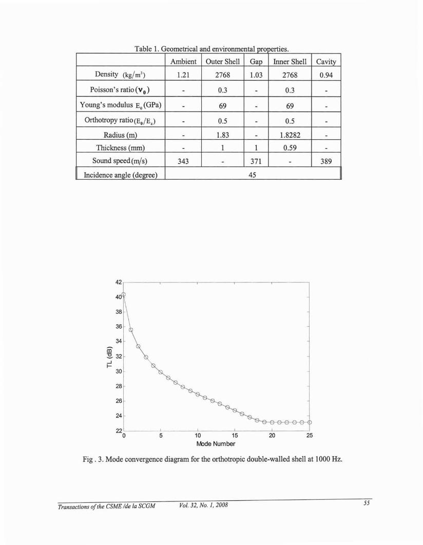
rtt IdtriT bi 1 Ga e eome ca an enVlfonmen a pro e les.
Ambient Outer Shell Gap Inner Shell Cavity
Density (kg/m 3) 1.21 2768 1.03 2768 0.94
Poisson's ratio (ve) - 0.3 - 0.3 -
Young's modulus Ee(GPa) - 69 - 69 -
Orthotropy ratio (Ee/Ez ) - 0.5 - 0.5 -
Radius (m) - 1.83 - 1.8282 -Thickness (mm) - I I 0.59 -
Sound speed(rnjs) 343 - 371 - 389
Incidence angle (degree) 45
42,-----.,.-----.---------r----..........-------,
34
en:s. 32....JI-
30
28
26
24
252010 15
rv10de Number5
22 "-- ..J -..L- -L. --'- ---'
o
Fig. 3. Mode convergence diagram for the orthotropic double-walled shell at 1000 Hz.
Transactions ofthe CSME /de la SCGM Vol. 32, No.1, 2008 55

100 ,----.----,----,--,----,-_-,-_-----,,---_,-_-,-_---,
ii:l70
~..JI- 60
50
40
300 20 40 60 80 100 120 140 160 180 200
tybde Number
Fig. 4. Mode convergence diagram for the orthotropic shell at 10000 Hz.
Coincidenceor Critical
ze"cY
\o.E:------~; Coincidence
Control
RingFrequency~
Stiffness Control
102
103
Frequency (Hz)
Fig. 5. Important frequencies and regions
Mass; Control ~
----------~ ~
140
120
100
-<E:80
ii:l~..J 60I-
40
20
0
10°
Transactions ofthe CSME Ide fa SCGM Vol. 32, No.1, 2008 56

9- Verification
To verify our work, an especial case of orthotropic double-walled cylindrical shell is considered wherethethicknessofairgapgoesbeyondzero(h g =O.OOlmm); Ez,Ea is substituted byE; v z, va by V
and G'2 by E/2(1+v). Three cases of single and double-walled cylindrical shells are specified as; 1single-walled shell using analytical method; 2- single-walled shell presented by "Blaise" [1] using"modal-impedance method" where the orthotropy ratio (x = Ea/EJ is one. 3- isotropic double-walled
shell presented by "Kim" [24]. The comparison of these methods, shown in Fig. 6, indicates a goodagreement. As depicted, comparison of our model with two earlier cases indicates that, there is nodifference between these results in stiffuess-controlled region. However in high frequency (especiallyhigher than coincidence frequency), it can be shown that calculated TL's in presented work have littledifference with those of "Blaise" orthotropic single shell. It might be the effect of air-gap in higherfrequencies as a result of shortening the wavelength and the resonance of annular space. The comparisonis also done with TL calculated by Kim & Lee for isotropic double-walled shell. This comparison showsthe same trend but a little difference can be shown in broadband of frequency.
100rr=============,.......,--~~~~...,.-~~-----:I-- Double shell- present study......... Single shell-analytical
80 - - - Single shell -Blaise-. _. - Double shell-Kim
60
co:s- 40...J.....
20
o
\,',I
-20 '-----~--'--'~............_~~~-'-'-'--_~~~u..J...._~~~~"'-'--~~--'--'....J
1~ 1~ 1~ 1~
Frequency (Hz)
Fig. 6. Comparison of present study with Blaise, Kim and analytical single-walled shell
10- Parametric studies
Parametric numerical studies of transmission loss (TL) are conducted for a double-walled orthotropiccylindrical shells specified in table (1) considering broadband frequency.
The effect of incident angle on longitudinal and radial wave number can make the TL be changed. Fig. 7
illustrates TL at y = 300 ,45 0 ,600
• Inspection of figure shows decreasing of incident angle trends to
Transactions ofthe CSME Ide fa SCGM Vol. 32, No.1, 2008 57

enhance the cylinder TL in stiffness-controlled region (below the ring frequency), and coincidencecontrolled region (upper than coincidence or critical frequency) since radial wave number is decreased.Additionally the coincidence frequency shifts upward.
160 r . -,' -,' ~,~, 'T - - ,-, ~ '-","1 . - ',-', -,' ~, n " - - ~ - ~, ~,- ~'l - • ~ . - ',., ,
I --YI=30140~
---y2=45
120L Y3=60I
100 ~-I
I
(C 8°1~...Jf-
20~
01-
-20 L . _,~ _,_ J... t. W ll.L __ J _ l ....L J....I.. ,_tJ.J • _ .1_ .1 _'. LJ J U I~ __ .L _ L l ..L ,_ I....l.d __ -t • ....I.. .,J
1~ 1~ 1~ 1~ 1~
Frequency (Hz)
Fig. 7. TL curves for the double-walled shell with respect to incidence angle
Figure 8. Compares the TL calculated from double shells of different air-gap sizes. Sound transmissionthrough the double shells with three air-gap sizes of 0.1, 1 and 10 mm are considered. It is illustrated thatthe air-gap size does not affect on the TL. in the frequency range lower than the ring frequency, becausethe wavelengths are larger than the air gap size. In other word the wavelengths do not sense the air-gap.In higher frequency, where the wavelengths are short, the air-gap plays the role of acoustic barrier. Inother hand, in high frequency range, enlarging the air -gap size make the TL be increased. In addition, byenlarging the air-gap size, the coincidence frequency shifts downwards (the mass-controlled region isdecreased.).
Different ambient conditions are considered here (table 2). A higher flight altitude affects on density and
sound velocity of fluid. Therefore, the acoustic impedance of external fluid (PIc I ) will be decreased.
Consequently, the difference between the acoustic impedances of fluids inside and outside the shells leadsto a larger acoustic mismatch. As shown in Fig. 9, increasing of acoustic mismatch makes the TL higherin broadband of frequency. For instance in some region it can be enhanced more than 10 dB. However,the ring frequency and coincidence frequency does not change.
Transactions ofthe CSME Ide la SCGM Vol. 32, No.1, 2008 58

100 ~
150 r·····,---,--,·.·,-.-.-,-,·,,---,---,··,,,-,,-,-,-,-' .. "---.--,','.-,-.,'.. ,'---,---.'.,",-,-,,,,--',.,,'--"-,-',
: h =001 mm :-- 9 . t-.- - h
g=1.00 mm f~
C...... '- hg=10.0mm r'~
1/ ;I' ",: J I1I: "
l,j::1
.' I I:" J'? i i
,or ~: /'i{:~, :50~" ' , I: :i 11' i: :
: "\ //\r--'~ J~WfJi(~ }'-i !
\ f ~ ,--,---.," \..- :\ '>-", /-A., ..........- :
: \1 //.. /'IA,:;/'" i. I \ ': f ',' .: I ",I ':,' , :o.""." --'.',". ""-'-." ---' ...',,'.' ,., """--" ..",",-',' ,','""",., --"- ,."__."".""'",.,".. ,', _,~10° 10
110
2103 104
Frequency (Hz)
Fig. 8. TL curves for double-walled shell with different gap size
140
120
100
en 80,
~...J
60I-
40
20
0
-2010°
-- 1sl Condition
- - - 2nd Condition
... ---- .. 3rd
Condition
102
103
Frequency (Hz)
Fig. 9. TL curves for three ambient conditions
Transactions ofthe CSME Ide la SCGM Vol. 32, No.1, 2008 59

T bl 2 FI" h d' .a e 19 t con ltIons.
Name First conditionSecond
Third conditioncondition
Altitude (m) 3050 7600 10650
Density (k~m3) 0.9041 0.5489 0.3795
Sound speed (m/s) 328.558 309.966 296.556
Inspection of the Fig.10 shows that decreasing the Orthotropy ratio (X = Eo/EJ (while Eo is held
constant) tends to enhance the cylinder TL in the stiffness-controlled region as well as decreasing dips.With increasing this ratio the ring frequency does not change, but critical frequency shifts upward. Itsuggests that the TL might be enhanced by making the shell less stiff in the circumferential direction thanit is in the axial direction.
250 r' , ,., ,.. '.' .,.,.", ,.. ,.,'." " , ,n'······.·· ., ?. ,
: --X=O.5 f
, -- - x=1.0 '200 ~ ......... X=2.0 )
f :,:/ :
150 ~
. ,
-50 ~ , c ••.••u> , , •••• , .>~ c ••••.•• , .'. ,>,~••••• > ••••••••• >., > c,;,
10° 101
102
103
104
Frequency (Hz)
Fig. 10. TL curves for the double-walled shell with respect to orthotropy ratio
External airflow can influence the axial and radial wave number. Figure 11, shows the effect of Machnumbers with M = 0, 0.2, and 0.4, on TL. With increasing Mach number, the TL is descending instiffness-controlled region, whereas in upper frequency more than ring frequency it is ascending.
Figure 12 shows the effect of the shell orthotropic material on the TL. The materials chosen for thecomparison are carbon, fiberglass/epoxy, graphite/epoxy as shown in table (3). The figure shows that thematerial must be chosen properly to enhance TL at stiffness-control zone. The axial and circumferential
Transactions ofthe CSME Ide la SCGM Vol. 32, No. I, 2008 60

modulus ratio play significant role. The best results are obtained from graphite/epoxy shell, whichrepresents a desirable level ofTL at stiffness-control zone. It is readily seen that, in higher frequency, as aresult of density of materials, the TL curves are ascending.
::I··~::~lum"Hummnm.mTu.,mmun:j
: ....•.... M=O.4 :'1120 ~ //
: :' I ~
100l /I.~. '1 :.
al 80l :~·;i~ : J1 :...J 60 ~ :.J~if- :' : fi
~"'-. /~
40: ·\~\.: ..>~~\·(·:::l~.>~.... /:' "/20 ~ \ :,"(. /' V:.! Ii I"::\~'" ~~"~'/'
: \i \/ \/ : I : I \)~<j ':.I~,o~ I , ; '.'
, ,
-20 ~ .....•.. >--"."" ••••••••••••••'.. ' ••••••• ; ••••••••••• >. >••••,>.'..... >••••••'••'.' .'.'" ••••• " --" ••••:
1~ 1~ 1~ 1~ 1~
Frequency (Hz)
Fig. 11. TL curves for double-walled shell subjected in uniform flow with different Mach numbers
160--Graphite/Epoxy
140 - - - Carbon/Epoxy/
-- Fiber/Epoxy /120 /
/100 /
/
al 80 f/
~ I...Jf- 60
40
20
0
-2010° 10
1102 103
104
Frequency (Hz)
Fig. 12. TL curves for double-walled shell using different material construction.
Transactions ofthe CSME Ide la SCGM Vol. 32, No.1, 2008 61

. IT bl 3 Ortha e OtrOplC matena s.
Name Graphite/ epoxy Carbon Fiberglass/epoxy
Density (kg/m3 ) 1600 1600 1900
E1 (GPa) 125 324 56
E2 (GPa) 10 5.86 56
Poisson's Ratio (VIZ) 0.4 0.26 0.25
GI2 (GPa) 5.9 1.1 4.2
As is seen in Fig. 13, changing the thickness of two shells has a broadband effect on TL over the entirerange of the frequency. In general, the TL increases about 6 dB as the thickness doubles, which is wellanticipated. In addition, the mass-controlled region is decreased. In a practical situation, the shells have tobe designed as thick as possible, unless there is a weight constraint. The type of analysis developed in thiswork will be very useful in such a situation. For example, if the target TL is known from theconsideration of the noise level, the proper thickness of the shell can be easily calculated.
-20L --L- --L- L....L1.....L..l..1l.- ---l --L...L-1..a...uU- _'--I -L-l-J...J.r.l.l- _1_1-L.L..J...J L..L.1. _ ..l....-L.......l.J
1~ 1~ 1~ 1~ 1~
Frequency (Hz)
Fig. 13. TL curves for double-walled shell with respect to shell thickness.
Transactions ofthe CSME Ide la SCGM Vol. 32, No.1, 2008 62

According to table (4) air and carbon dioxide properties is used to analyze the effect of gap fluidproperties on the TL. As shown in Fig. 14, there is no difference in lower frequency but in highfrequency, the TLs of carbon dioxide gap is higher than those of air gap because of higher impedancemismatch.
T bl 4 G fl'da e ap U1 . propemes
Name Density (kg/m3)Sound Characteristic
speed(m/s) impedance
Air 1.184 346.1 409.8
Carbon dioxide 1.799 269.5 484.7
--Air Gap
- - - Dioxide Gap
100
I/'\/ \ I
! V/
/I
50
O'-----'--'--"'-'-'-U-Ll.._-'-"-'-''-'-U-'"---'---'-~'_'_U._'__~~~~_~''_____'..J
1~ 1~ 1~ 1~ 1~
Frequency (Hz)
Fig. 14. TL curves for double-walled sell using different gap fluid properties.
11- Concluding remarks
Analytical studies are conducted on vibro-acoustic behavior of an infinitely long orthotropic doublewalled cylindrical shell, subjected to a plane sound wave. Acoustic wave equations and shell equations,which are coupled with one another, are solved simultaneously to calculate TL. The effects of differentparameters on TL are considered in numerical results. The following conclusion can be drawn from thisnumerical study:
Transactions ofthe CSME Ide la SCGM Vol. 32, No.1, 2008 63
1- Decreasing the incident angle trends to enhance the cylinder TL in stiffness-controlled region andcoincidence-controlled region.
2- Decreasing the Orthotropy ratio tends to enhance the cylinder TL in the stiffness-controlled region aswell as decreasing dips.
3- In higher altitude, acoustic impedance mismatch increases. Therefore, TL in all broadband offrequency is enhanced.
4- In high frequency range, enlarging the air -gap size make the TL be increased. Moreover, by enlargingthe air-gap size, the coincidence frequency shifts downwards.
5- Increasing the Mach number descends the TL in stiffness-controlled region, whereas in upperfrequency more than ring frequency it is ascending.
6- The comparison of our investigation with the results done by other author indicates a good agreement.
References
[1] Dowell E.H., Master plan for prediction of vehicle interior noise., American Institute of Aeronauticsand Astronautics Journal, Vol. 18, 1980,353-366.
[2] Smith P. W., Sound transmission through thin cylindrical shells. Journal of the Acoustical Society ofAmerica 29 (1957) 721-729.
[3] Koval L.R, On sound transmission into a thin cylindrical shell under flight conditions, Journal ofSound and Vibration, Vol. 48, 1976,265-275.
[4] Koval L.R" On sound transmission into an orthotropic shell, Journal of Sound and Vibration, Vol. 63,1979,51-59.
[5] Koval L.R., Sound transmission into a laminated composite cylindrical shell, Journal of Sound andVibration, Vol. 71, 1980,523-530.
[6] Blaise A., Lesueur C., Gotteland M., Barbe M., On sound transmission into an orthotropic infiniteShell: comparison with Koval result and understanding the phenomena.,Journal of Sound and Vibration,Vol. 150,1991,233-243.
[7] Tang Y. Y., Robinson J. H., Silcox R J., Sound transmission through a cylindrical sandwich shellwith honeycomb core, 34th AIAA Aerospace Science Meeting and Exhibit (AIAA-96-0877), 1-4, 1996.
[8] Lee J. H., Kim J., Study on sound transmission characteristics of a cylindrical shell using analytical anexperimental models, Applied Acoustic, Vol. 64, 2003, 611-632.
[9] Daneshjou K., Nouri A., Talebitooti R, Sound Transmission through Laminated CompositeCylindrical Shells Using Analytical Model, Archive of Applied Mechanics, Vol 77, 2007, 363-379.
[10] Coats T. J., Silcox R J., Lester H. c., Numerical study of active structural acoustic control in adouble walled cylinder, Second Conference on Recent Advances in Active Control of Sound andVibration, Blacksburg, Virginia, April 28-30, 1993., s11-s27,
[11] Tang Y. Y., Silcox R J., Robinson J. H., Sound transmission through two concentric cylindricalsandwich shells, Proceedings of the 14th International Modal Analysis Conference Japan, 1488-1492,1996.
[12] Grosveld F. W., Coats T. J., Lester H. C., Silcox R J., A numerical study of active structural acousticcontrol in a stiffened, double wall cylinder, Noise-Con 94, Ft. Lauderdale, Florida, May 01-04, 1994.
Transactions ofthe CSME Ide la SCGM Vol. 32, No.1, 2008 64

[13] Ford R. D., Lord P., Williams P. C., The influence of absorbent linings on the transmission loss ofdouble leaf partitions., Journal of sound and Vibration, Vol. 5(1), 1967,22-28
[14] Grooteman F. P., Boer D., Schippers H., Vibroacoustic analysis of double wall Structures, TheCEAS/AIAA 1st Joint Aero acoustic Conference, Munich, Germany, Jun. 12-15, 1995, 1049-1053.
[15] London A, Transmission of reverberate sound through double walls, Journal of Acoustical Societyof America, Vol. 22(2), 1950,270-279.
[16] Mulholland K. A, Parbrook H. D., Cummings A, The transmission loss of double panels. Journal ofsound and Vibration, Vol. 6(3), 1967,324-334.
[17] White P. H., Powell A., Transmission of random sound and vibration through a rectangular doublewall. Journal of Acoustical Society of America, Vol. 44(4), 1966,821-832.
[18] Lee J. H., Kim J., Analysis and measurement of sound transmission through a double-walledcylindrical shell, Journal of Sound and Vibration, Vol. 251(4), 2002, 631-649
[19] Qatu M. S., Vibration oflaminated hells and plates, Elsevier Academic Press, 2004.
[20] Howe M. S., Acoustics of Fluid-Structure mteraction, Cambridge Diversity press, 2000.
[21] Markus S., The mechanics of vibrations & cylindrical shells, Elsevier, 1988 .
[22] Ventsel E., Krauthammer T., Thin plates and shells, Marcel Dekker, inc., 2001.
[23] Leissa, A, Vibration of shells, NASA SP288, 1973.
[24] Soedel W., Vibrations of shells and plates, New York: Marcel Dekker, mc., 1993.
[25] Fahy F., Sound and structural vibration: radiation, transmission and response, Academic press, NewYork, NY, 1985.
[26] Mclachlan N. W., Bessel function for engineers, Oxford University press, second Edition, 1955.
[27] Pierce A D., Acoustics, New York: McGraw-Hill, 1981.
[28] Norton M., Karczub D., Fundamentals of noise and vibration analysis for engineers, CambridgeUniversity press, Second Edition, 2003.
[29] Gerald F., wheatley P.O., Applied numerical analysis, Addison-Wesley, 1997.
Nomenclature
nV1:
W
cl'C Z ,c 3
Cij
Dij
EI'E Z
hl'h Z
Circumferential mode numberVelocity of the external flowpower transmission coefficientAngular frequencySpeed of sound in external, gap, and cavity media
Extensional stiffness constants
Flexural stiffness constants
Modulus of elasticity for inner and outer shell
Thicknesses of the inner and outer shells
Transactions ofthe CSME Ide la SCGM Vol. 32, No. J, 2008 65

H~,H~
I n
kl'k Z ,k 3
M,
PoI R R T T
P ,PI ,PZ ,PZ ,P3
R"R zo 0 0
U i ,Vi ,Wi
Hankel functions of the first and second kind of order n
Bessel function of the first kind of order n
Wave numbers in external, gap and internal media
Mach number of the external flow
Amplitude of the incident wave
Incident wave, reflected wave from the outer and inner shell,transmitted wave through the outer and inner shellRadii and thicknesses of the inner and outer shells
Displacements of the shell in the axial, circumferential, and radialdirections at the neutral surfaceIncident and transmitted power flow per unit length of the shell
Neumann factor
Incident angle
critical angles of incidence upon the shell
Poisson ratios of inner and outer shells
Density of external medium, Gap and internal medium
Density of inner and outer shells
Transactions ofthe CSME Ide fa SCGM Vol. 32, No.1, 2008 66