AN R T F - maine.gov · 502.83 PRECAST BLOCK MAT 1119 SF COFFERDAM: (WEST ABUTMENT) ... Contractor...
12
Transcript of AN R T F - maine.gov · 502.83 PRECAST BLOCK MAT 1119 SF COFFERDAM: (WEST ABUTMENT) ... Contractor...


BRID
GE
Divisio
n:
Filena
me:...\
BRID
GE\
MS
TA\
002
_Estim
ate.d
gn
Userna
me:
Date:5/6/2
014
gerald.lib
by
ESTIMATED QUANTITIES
ITEM NO. QUANTITYDESCRIPTION UNIT
DE
SIG
N-
DE
TAIL
ED
BY
DA
TE
PR
OJ.
MA
NA
GE
R
SHEET NUMBER
FIE
LD
CH
AN
GE
S
RE
VISIO
NS
1
RE
VISIO
NS
2
RE
VISIO
NS
3
RE
VISIO
NS
4
CH
EC
KE
D-
RE
VIE
WE
D
OF
DE
SIG
N2-
DE
TAIL
ED
2
DE
SIG
N3-
DE
TAIL
ED
3
BRID
GE P
LA
NS
DE
PA
RT
ME
NT O
F T
RA
NSP
OR
TA
TIO
N
ST
AT
E O
F M
AIN
E
DA
TE
SIG
NA
TU
RE
P.E.
NU
MB
ER
__
__
_
2
STP-2
051(0
00)
6
20510.0
0
MO
OS
E
BR
OO
K
BRID
GE
MO
OS
E
BR
OO
K
HO
UL
TO
NA
RO
OS
TO
OK
CO
UN
TY
BRID
GE N
O. 2580
__
__
__
__
__
__
__
__
__
__
__
__
__
__
__
__
__
__
__
__
__
__
__
__
__
__
__
__
__
__
B.
RE
EV
ES
M.R.P.
__
__
__
__
__
__
__
__
__
__
__
__
__
__
__
__
__
__
S.
BO
DG
E
511.07
511.07
610.16
613.319 EROSION CONTROL BLANKET
615.0701
618.1401
619.1201
LOAM - PLAN QUANTITY
MULCH - PLAN QUANTITY
SEEDING METHOD NUMBER 2 - PLAN QUANTITY
EROSION CONTROL MIX619.1401
620.58 EROSION CONTROL GEOTEXTILE
629.05 HAND LABOR, STRAIGHT TIME
631.172
652.33
652.34
652.35
652.361
652.38
656.75
659.10
TRUCK - LARGE (INCLUDING OPERATOR)
DRUM
CONE
CONSTRUCTION SIGNS
MAINTENANCE OF TRAFFIC CONTROL DEVICES
FLAGGER
TEMPORARY SOIL EROSION AND WATER POLLUTION CONTROL
MOBILIZATION
(60 CD)
LS
LS
CY
SY
SY
HR
HR
HR
EA
EA
SF
LS
HR
LS
LS
CY
CY
UN
UN
1
1
22
7
1
1
7
20
20
20
25
25
1
1
1
502.83 PRECAST BLOCK MAT 1119 SF
COFFERDAM: (WEST ABUTMENT)
EAFIELD OFFICE, TYPE B
110
GG
L
518.60 SFREPAIR OF VERTICAL SURFACE <7.9 IN.
WIN
35
HEAVY RIPRAP
ALL PURPOSE EXCAVATOR (INCLUDING OPERATOR)
100
98
518.61 REPAIR OF VERTICAL SURFACE >7.9 IN. 2 CY
ES
TI
MA
TE
D
QU
AN
TITIE
S
0.5
73
GENERAL CONSTRUCTION NOTES
the Resident.
the installation may need to be altered to fit actual site conditions as directed by
16. Sections shown on the design plans depict "Typical" conditions and the intent of
be paid for directly and will be considered incidental to the related contract items.
will determine final streambed elevation(s) based on this information. This work shall not
shall be taken every 5 feet along all three lines and provided to the Resident. Resident
downstream bridge fascia and along the centerline of the bridge. Streambed elevations
15. Contractor shall verify stream bed elevations along the upstream bridge fascia,
Contract Items.
14. Grout testing and curing boxes shall be considered incidental to related
an actual quantities installed to the satisfaction of the Resident.
13. Estimates of quantities are necessarily approximate. Payment will be made on
to fit site conditions.
represent the minimum dimensions desired. The Resident may direct modifications
12. Areas shown of the countermeasure installation are approximate and
Compensation.
with Standard Specifications Section 109.7, Equitable Adjustments to
Lump Sum pay items, price adjustments will be made in accordance
c. If a design change results in changes to estimated quantities for
for a Lump Sum pay item, those requirements will be followed.
b. If other Contract Documents specifically allow a change in payment
Specifications Section 109.2, Elimination of Items, will take precedence.
a. If a Lump Sum pay item is eliminated, the requirements of Standard
quantities, except as follows:
actual final quantities are different from the MaineDOT provided estimated
amount, with no addition or reduction in payment to the Contractor if the
purposes only. Lump Sum pay items will be paid for at the Contract Bid
are estimated quantities and are provided by MaineDOT for informational
11. Quantities included for pay items measured and paid for by Lump Sum
to the bridge during its life span.
any construction field changes or any alterations which may have been made
for the construction of the bridge. It is very unlikely that the plans will show
address. The plans are reproductions of the original drawings as prepared
10. The existing bridge plans may be accessed at the MaineDOT web
projects/project-information.php.
MaineDOT web address: http://www.maine.gov/mdot/comprehensive-list-
9. Project information referred to below may be accessed at the following
projects/project-information.php.
web address: http://www.maine.gov/mdot/comprehensive-list-
8. Scour Plan of Action (POA) may be accessed at the following MaineDOT
sideslopes along the top of the riprap and behind the wingwalls.
7. Place a 24-in. wide strip of Temporary Erosion Control Blanket on the
made under Item No. 619.1401, Erosion Control Mix.
accordance with Standard Specifications Section 619, Mulch. Payment will be
receiving loam and seed as directed by the Resident. Placement shall be in
6. Erosion Control Mix may be substituted in those areas normally
directed by the Resident.
5. Place loam 2 inches deep on all new or reconstructed sideslopes or as
and down stream sideslope up to EL. 400’.
4. Place heavy riprap on up stream sideslopes up to EL. 400’
otherwise noted.
3. All utility facilities shall be adjusted by the respective utilities unless
will be considered incidental to Contract items.
limits will be established in the field by the Resident. Payment for clearing
2. The clearing limits as shown on the plans are approximate. The exact
of Way Map.
1. For easements, construction limits and right of way lines, refer to Right
COFFERDAM: (EAST ABUTMENT)
518.70 REPAIR OF OVERHEAD SURFACES <7.9 IN. 5 SF
M.R.P.
M.R.P.
GG
L
639.19
631.12

E = 0.25’
T = 31.88’
L = 63.75’
R = 2000.00’
PI = 8+79.39
CURVE DATA #2
PO
E
=
ST
A. 9
+22.10
6+00 6+506+25
5+75 6+00 6+25 6+50
380
385
390
395
400
405
410
380
385
390
395
400
405
410
375 375
Varies
PROFILE 0
Existing gradeExisting superstructure
Footing
Existing
Abut.
Exist.
Abut.
Exist.
Footing
Existing
5 5 10
Scale in Feet
Excavate as necessary
special provision 502 (Typ.)
and wingwall per
along abutment
Must be sealed
@ É of Roadway
Existing Streambed
To Houlton
DE
SIG
N-
DE
TAIL
ED
BY
DA
TE
PR
OJ.
MA
NA
GE
R
SHEET NUMBER
FIE
LD
CH
AN
GE
S
RE
VISIO
NS
1
RE
VISIO
NS
2
RE
VISIO
NS
3
RE
VISIO
NS
4
CH
EC
KE
D-
RE
VIE
WE
D
BRID
GE
Divisio
n:
Filena
me:...\
00\
BRID
GE\
MS
TA\
003
_B
DPla
n1.d
gn
Userna
me:
Date:2/2
4/2
014
co
mm
on
OF
DE
SIG
N2-
DE
TAIL
ED
2
DE
SIG
N3-
DE
TAIL
ED
3
BRID
GE P
LA
NS
ST
AT
E O
F M
AIN
E
DE
PA
RT
ME
NT O
F T
RA
NSP
OR
TA
TIO
N
DA
TE
SIG
NA
TU
RE
P.E.
NU
MB
ER
20510.0
0
HO
UL
TO
N
BRID
GE N
O. 2580
STP-2
051(0
00)
MO
OS
E
BR
OO
K
BRID
GE
AR
OO
ST
OO
K
CO
UN
TY
B.
RE
EV
ES
M.R.P.
S.
BO
DG
E
36
MO
OS
E
BR
OO
K
GE
NE
RA
L
PL
AN
S
&
PR
OFIL
E20510.0
0
To New Limerrick
CABLE MAT
PRECAST CONCRETE
Scale of Feet
PLAN
25 0 25 50
10’-0" –
10’-0" –
HEAVY RIPRAP (Typ.)
10’-0" –
7’-6" –
4+00 5+00 6+00 7+00 8+00 9+00PO
B
=
ST
A. 3
+66.76
PT =
ST
A. 5+
00.0
0
PC
=
ST
A. 8+
47.5
1
PT
=
ST
A. 9
+11.27
PC
=
ST
A. 3
+77.70
Flo
w
Moose B
rook
A A
B
B
C
C
Route 2#2580
4" TWIN
#2580
HOUSE #516 2 STY
PANEL MARKER
JOINT #62
FIELD ENT
DELINEATOR
NARROW BRIDGE
LAWN
LAWN
15" CMP
15" CMP
15" CMP
LAWN
#508#510
DELINEATOR
DELINEATOR
DELINEATOR
GRAVEL
GRAVEL
MARKER
PANEL
ELEV
WATER
JOINT #63WOOD
4x4
WOOD
4x4 GRANITE
3x3
GRANITE
3x3
CURVE AHEAD
JOINT #61
E = 0.47’
T = 61.16’
L = 122.30’
R = 4000.00’
PI = 4+38.85
CURVE DATA #1
395
395
400
400400
400400
400
400
(typ.)see note 2 on Pg. 4
Precast Concrete Block Mat

Varies
Footing
Existing
Footing
Existing
Excavate as necessary
Existing Streambed
Easterly AbutmentWesterly Abutment
É Channel
Typ.
2
1
Erosion Control Filter Layer
SECTION A-A
Wingwall per special provision 502.
Must be sealed along Abutment and
DE
SIG
N-
DE
TAIL
ED
BY
DA
TE
PR
OJ.
MA
NA
GE
R
SHEET NUMBER
FIE
LD
CH
AN
GE
S
RE
VISIO
NS
1
RE
VISIO
NS
2
RE
VISIO
NS
3
RE
VISIO
NS
4
CH
EC
KE
D-
RE
VIE
WE
D
BRID
GE
Divisio
n:
Filena
me:...\
MS
TA\
004
_Precast_
mat.d
gn
Userna
me:
Date:2/2
4/2
014
co
mm
on
OF
DE
SIG
N2-
DE
TAIL
ED
2
DE
SIG
N3-
DE
TAIL
ED
3
BRID
GE P
LA
NS
ST
AT
E O
F M
AIN
E
DE
PA
RT
ME
NT O
F T
RA
NSP
OR
TA
TIO
N
DA
TE
SIG
NA
TU
RE
P.E.
NU
MB
ER
__
__
_
STP-2
051(0
00)
20510.0
0
MO
OS
E
BR
OO
K
BRID
GE
HO
UL
TO
NA
RO
OS
TO
OK
CO
UN
TY
BRID
GE N
O. 2580
__
__
__
__
__
__
__
__
__
__
__
__
__
__
__
__
__
__
__
__
__
__
__
__
__
__
__
__
__
__
__
__
__
__
__
B.
RE
EV
ES
M.R.P.
__
__
__
__
__
__
__
__
__
__
__
__
__
__
__
__
__
__
__
__
__
__
__
__
S.
BO
DG
E
46
MO
OS
E
BR
OO
KG
GL
CO
UN
TE
RM
EA
SU
RE
DE
TAIL
SWIN
Existing Streambed
SECTION B-B
NOTE: Upstream shown, downstream similar
necessary
Excavation as
Special Provision 502.
in accordance with
shall be anchored
downstream edge
Upstream andErosion Control Filter Layer
Precast Block Mat
SECTION C-C
As shown on plans
Existing Bank
Wrap about Wingwalls
Heavy Riprap
Erosion Control Geotextile
Protective Aggregate Cushion
Erosion Control Filter Layer
Min.
4’-0
"
6"
Min.
Precast Block Mat
5’-0" –
downstream transition of low flow channel to existing streambed shall be as directed by the Resident.
4. For required low flow channel dimensions, see the related countermeasure specification. Upstream and
threaten the stability of the bridge foundations or retaining wall foundations.
countermeasure shall match the existing streambed. The Contractor’s work shall not undermine or otherwise
3. To the maximum extent possible, except to create a low flow channel, the top surface of the scour
2. The thickness of the cable mats shall be 4� inches.
cable mats shall be considered incidental to Item 502.83.
the stone fill. Precast block mats shall bear directly on geotextile fabric. Geotextile fabric under concrete
1. The protective aggregate cushion of the erosion control filter layer shall be six (6) inches thick beneath
NOTES:
(See note 2 on Pg. 4)
Precast Block Mat (Typ.)

DE
SIG
N-
DE
TAIL
ED
BY
DA
TE
PR
OJ.
MA
NA
GE
R
SHEET NUMBER
FIE
LD
CH
AN
GE
S
RE
VISIO
NS
1
RE
VISIO
NS
2
RE
VISIO
NS
3
RE
VISIO
NS
4
CH
EC
KE
D-
RE
VIE
WE
D
BRID
GE
Divisio
n:
Filena
me:...\
005
_Abut
ment_
Repair
_Details.d
gn
Userna
me:
Date:2/2
4/2
014
co
mm
on
OF
DE
SIG
N2-
DE
TAIL
ED
2
DE
SIG
N3-
DE
TAIL
ED
3
BRID
GE P
LA
NS
ST
AT
E O
F M
AIN
E
DE
PA
RT
ME
NT O
F T
RA
NSP
OR
TA
TIO
N
DA
TE
SIG
NA
TU
RE
P.E.
NU
MB
ER
__
__
_
5
STP-2
051(0
00)
6
20510.0
0
MO
OS
E
BR
OO
K
BRID
GE
MO
OS
E
BR
OO
K
HO
UL
TO
NA
RO
OS
TO
OK
CO
UN
TY
BRID
GE N
O. 2580
__
__
__
__
__
__
__
__
__
__
__
__
__
__
__
__
__
__
__
__
__
__
__
__
__
__
__
__
__
__
__
__
__
__
__
B.
RE
EV
ES
M.R.P.
GG
L
__
__
__
__
__
__
__
__
__
__
__
__
__
__
__
__
__
__
S.
BO
DG
E
RE
PAIR
DE
TAIL
S
VE
RTIC
AL
SU
RF
AC
E
1. The exact dimensions for Repair of Vertical Surfaces shall be determined by the Resident in the field.
NOTES:
WIN
6’-3"
Existing Bridge
A
A
NE Wingwall
Area Along 1’-0"
2’-0" –
Flow
NE Wingwall
Face of Existing
East Abutment
2’-0"
1’-0
"KEY
- Indicates Area for Repair
2’-0"
SE Wingwall
Face of Existing
2’-0"
6"
Top of Abutment Footing (Location & Size TBD by Resident)
Area Along SE Wingwall
É Roadway
Field
Measure
Construction Joint
West Abutment
6’-3"
Existing Bridge
3’-0"
4’-0"
2’-6"
1’-6"
KEY
- Indicates Area for Repair
1’-0
" –
3’-6" –
Flow
SW Wingwall
Face of Existing
Top of Abutment Footing
NW Wingwall
Face of Existing
TBD by Resident
Actual Location and Size
É Roadway
Field
Field
Measure
Measure
Construction Joint
9"
8’-6" –
Section A - A
for T Beam (Upstream)
Area of Surface Repair
To Houlton
NE Wingwall
Face of Existing

NO. GRANTOR INSTRUMENT DATE BOOK PAGE
COUNTY RECORDSHEET NUMBER
OFDATE
COMMISSIONER
CHIEF ENGINEER
REVISIONS
NO. DATE DESCRIPTION BY
SY
MB
OLS
(SE
PTIC T
AN
K)
WA
TE
R LIN
E
GA
S LIN
E
ELE
CT
RIC LIN
E
TE
LE
PH
ON
E LIN
E
SE
WE
R LIN
E
PR
OP
ER
TY LIN
E
EXIS
TIN
G RIG
HT O
F W
AY
CO
NT
RO
L O
F A
CC
ES
S
NE
W RIG
HT O
F W
AY
RIG
HT O
F W
AY M
AP
ST
AT
E O
F M
AIN
E
DE
PA
RT
ME
NT O
F T
RA
NSP
OR
TA
TIO
N
16 S
TA
TE H
OU
SE ST
ATIO
N - A
UG
UST
A, M
E 0
4333-0
016
NE
W R
OW W
ITHIN E
XIS
T.
RO
W
BM
GR
ADIN
G LIM
IT LIN
E
CO
NS
TR
UC
TIO
N LIM
IT LIN
E PL
(WE
LL)
(RO
W M
ON
UM
EN
T)
(TR
AV
ER
SE P
OIN
T)
ITE
MT
EC
HC
HE
CK
ED
BA
SE
MA
P
EXIS
T.
R/
W
PR
OP.
LIN
ES
AR
EA
S
RIGHT-OF-WAY MAP
WIN
SCALE 1"= 25’
PLAN FILED IN PLAN BOOK PAGE
BRID
GE
Divisio
n:
Filena
me:...\
00\
RO
W\
MS
TA\
001_
RW
PL
AN
1.d
gn
Userna
me:
Date:2/2
4/2
014
co
mm
on
S.T.
WW
GG
EE
TT
WE
LL
(IR
ON PIP
E or PIN F
OU
ND)
IPor
IPF
LIM
ITS O
F W
RO
UG
HT P
OR
TIO
N (
L.O.W.P.)
66
20510.00
HOULTON
HO
ULT
ON
AROOSTOOK COUNTY
DAVID BERNHARDT
JOYCE NOEL TAYLOR
FEDERAL AID PROJECT NO. STP-2051(000)
BRIDGE NO. 2580 MOOSE BROOK
OVER
MOOSE BROOK BRIDGE
SHEET 1 OF 1
D.S.G.
FEBRUARY 2014
STATE HIGHWAY "319"
THIS PLAN WAS PREPARED IN CONNECTION WITH THE DEPARTMENT’S ACQUISITION OF
ESTABLISH LEGAL BOUNDARIES BETWEEN ABUTTING PROPERTY OWNERS.
REAL PROPERTY FOR TRANSPORTATION PURPOSES. IT CANNOT BE USED TO
U.S. ROUTE 2
D.O.T. FILE NO. 2-562
E = 0.25’
T = 31.88’
L = 63.75’
R = 2000.00’
PI = 8+79.39
CURVE DATA #2
PO
E
=
ST
A. 9
+22.10
GRID 19
XX
ZO
NE
4+00 5+00 6+00 7+00 8+009+00
PO
B
=
ST
A. 3
+66.76
PT
=
ST
A. 5
+00.00
PC
=
ST
A. 8
+47.51
PT
=
ST
A. 9
+11.27
SEE S.H.C. FILE NO. 2-19
66’ RIGHT OF WAY
TO OTHERS
NOTE: RIGHTS CONVEYED TO
PHILIP R. BROWN AND PHYLLIS M. BROWN
TO MAINTAIN A WATER PIPE FROM
MOOSE BROOK S.A.R.O.D. BK. 1014 PG. 28
(UNSURE OF LOCATION)N/F PHILIP R. BROWN
COREY AUSTIN
GLORIA AUSTIN
P.L.
P.L.
P.L.
P.L. F
OLLO
WS
BR
OO
K
P.L. FO
LLOW
S BRO
OK
122.30’
B.L.
BEGIN
347.51’
B.L.
END
N 83°-03’-50.2" E
+25+25
TE
MP
OR
AR
Y
CONSTRUCTION
LIM
ITS
+94*+29*
1710�
0.17î�
REGIS L. BEAULIEU
LOIS C. BEAULIEU
ITEM NO. (1)
TEMP. CONST. RIGHTS = 1710* S.F. (1)
TOTAL AREA = 14* AC. (PER TOWN)
ANDREW F. MOOERS
ITEM NO. (3)
TEMP. CONST. RIGHTS = 0.17* AC. (1)
TOTAL AREA = 207.81* AC. (PER TOWN)
+50
+65
TE
MPO
RARY
CONSTRUCTION
LIMIT
S1525�
0.07î�
BRENT DICKISON
JANE K. DICKISON
ITEM NO. (2)
TEMP.CONST. RIGHTS = 1525* S.F. (1)
TOTAL AREA = 1.6* AC. (PER TOWN)
MICHAEL R. SCOTT
TENNILLE L. SCOTT
ITEM NO. (4)
TEMP.CONST. RIGHTS = 0.07* AC. (1)
TOTAL AREA = 6.0* AC. (PER TOWN)
STATE HIGHWAY "319"
TO NEW LIMERICK U.S. ROUTE 2
TO HOULTON
FEB. 1934
S.H.C. FILE NO. 2-19
SEE ALSO:
1865 4 RODS WIDE (THIS AREA)
VOL. 2 PAGE 372
COMMISSIONER RECORDS
AROOSTOOK COUNTY
EXISTING R/W
PC
=
ST
A. 3
+77.70
Moose Brook
+42*+20*
Flo
w
Sill E
L
#2580
4" TWIN
#2580
HOUSE #516 2 STY
PANEL MARKER
JOINT #62
FIELD ENT
DELINEATOR
NARROW BRIDGE
LAWN
LAWN
15" CMP
15" CMP
15" CMP
LAWN
#508#510
DELINEATOR
DELINEATOR
DELINEATOR
GRAVEL
GRAVEL
MARKER
PANEL
ELEV
WATER
JOINT #63 WOOD
4x4
WOOD
4x4 GRANITE
3x3
GRANITE
3x3
CURVE AHEAD
JOINT #61
E = 0.47’
T = 61.16’
L = 122.30’
R = 4000.00’
PI = 4+38.85
CURVE DATA #1


BRID
GE
Divisio
n:
Filena
me:...\
BRID
GE\
MS
TA\
002
_Estim
ate.d
gn
Userna
me:
Date:5/6/2014
gerald.lib
by
ESTIMATED QUANTITIES
ITEM NO. QUANTITYDESCRIPTION UNIT
DE
SIG
N-
DE
TAIL
ED
BY
DA
TE
PR
OJ.
MA
NA
GE
R
SHEET NUMBER
FIE
LD
CH
AN
GE
S
RE
VISIO
NS 1
RE
VISIO
NS 2
RE
VISIO
NS 3
RE
VISIO
NS 4
CH
EC
KE
D-
RE
VIE
WE
D
OF
DE
SIG
N2-
DE
TAIL
ED
2
DE
SIG
N3-
DE
TAIL
ED
3
BRID
GE P
LA
NS
DE
PA
RT
ME
NT O
F T
RA
NSP
OR
TA
TIO
N
ST
AT
E O
F M
AIN
E
DA
TE
SIG
NA
TU
RE
P.E.
NU
MB
ER
ES
TI
MA
TE
D
QU
AN
TITIE
S
2
STP-2
051(1
00)
20511.0
0
RE
D
BRID
GE
"B" S
TR
EA
M
HO
UL
TO
NA
RO
OS
TO
OK
CO
UN
TY
BRID
GE N
O. 2706
6
502.83 PRECAST BLOCK MAT
511.07
511.07
613.319 EROSION CONTROL BLANKET
COFFERDAM: ABUTMENT NO 1
LOAM - PLAN QUANTITY
MULCH - PLAN QUANTITY
620.58
629.05
631.121
619.1401
615.0701
618.1401
619.1201
COFFERDAM: ABUTMENT NO 2
631.172
652.33
652.34
652.35
652.361
652.38
656.75
659.10
EROSION CONTROL GEOTEXTILE
HAND LABOR, STRAIGHT TIME
HEAVY DUTY ALL PURPOSE EXCAVATOR (INCLUDING OPERATOR)
TRUCK - LARGE (INCLUDING OPERATOR)
DRUM
CONE
CONSTRUCTION SIGNS
MAINTENANCE OF TRAFFIC CONTROL DEVICES
FLAGGER
TEMPORARY SOIL EROSION AND WATER POLLUTION CONTROL
MOBILIZATION
EROSION CONTROL MIX
SEEDING METHOD NUMBER 2 - PLAN QUANTITY
SF
1
1
47
20
20
20
25
25
1
1
1
LS
LS
SY
SY
HR
HR
HR
EA
EA
SF
LS
HR
LS
LS
18 CY
9 CY
2
2
UN
UN
(60 CD)
CY610.16 HEAVY RIPRAP
518.60 SFREPAIR OF VERTICAL SURFACE <7.9 IN. 350
WIN
4,817
552
639.19 EAFIELD OFFICE - TYPE B
110
100
414
518.61 CYREPAIR OF VERTICAL SURFACE >7.9 IN. 2
0.5
BJ
RBJ
N
SD
B
the Resident.
the installation may need to be altered to fit actual site conditions as directed by
16. Sections shown on the design plans depict "Typical" conditions and the intent of
be paid for directly and will be considered incidental to the related contract items.
will determine final streambed elevation(s) based on this information. This work shall not
shall be taken every 5 feet along all three lines and provided to the Resident. Resident
downstream bridge fascia and along the centerline of the bridge. Streambed elevations
15. Contractor shall verify stream bed elevations along the upstream bridge fascia,
Contract Items.
14. Grout testing and curing boxes shall be considered incidental to related
an actual quantities installed to the satisfaction of the Resident.
13. Estimates of quantities are necessarily approximate. Payment will be made on
to fit site conditions.
represent the minimum dimensions desired. The Resident may direct modifications
12. Areas shown of the countermeasure installation are approximate and
Compensation.
with Standard Specifications Section 109.7, Equitable Adjustments to
Lump Sum pay items, price adjustments will be made in accordance
c. If a design change results in changes to estimated quantities for
for a Lump Sum pay item, those requirements will be followed.
b. If other Contract Documents specifically allow a change in payment
Specifications Section 109.2, Elimination of Items, will take precedence.
a. If a Lump Sum pay item is eliminated, the requirements of Standard
quantities, except as follows:
actual final quantities are different from the MaineDOT provided estimated
amount, with no addition or reduction in payment to the Contractor if the
purposes only. Lump Sum pay items will be paid for at the Contract Bid
are estimated quantities and are provided by MaineDOT for informational
11. Quantities included for pay items measured and paid for by Lump Sum
GENERAL CONSTRUCTION NOTES
to the bridge during its life span.
any construction field changes or any alterations which may have been made
for the construction of the bridge. It is very unlikely that the plans will show
address. The plans are reproductions of the original drawings as prepared
10. The existing bridge plans may be accessed at the MaineDOT web
projects/project-information.php.
MaineDOT web address: http://www.maine.gov/mdot/comprehensive-list-
9. Project information referred to below may be accessed at the following
projects/project-information.php.
web address: http://www.maine.gov/mdot/comprehensive-list-
8. Scour Plan of Action (POA) may be accessed at the following MaineDOT
sideslopes along the top of the riprap and behind the wingwalls.
7. Place a 24-in. wide strip of Temporary Erosion Control Blanket on the
made under Item No. 619.1401, Erosion Control Mix.
accordance with Standard Specifications Section 619, Mulch. Payment will be
receiving loam and seed as directed by the Resident. Placement shall be in
6. Erosion Control Mix may be substituted in those areas normally
directed by the Resident.
5. Place loam 2 inches deep on all new or reconstructed sideslopes or as
and down stream sideslope up to EL. 337’.
4. Place heavy riprap on up stream sideslopes up to EL. 340’
otherwise noted.
3. All utility facilities shall be adjusted by the respective utilities unless
will be considered incidental to Contract items.
limits will be established in the field by the Resident. Payment for clearing
2. The clearing limits as shown on the plans are approximate. The exact
of Way Map.
1. For easements, construction limits and right of way lines, refer to Right
M.R.P.
G.
LIB
BY
Sill E
L
Sill E
L
W
PAVED
U-HAUL RENTALS6"
CMP
PAVED
METAL GATE
JOINT #15
TRACTOR TRAILER BODY
JOINT #17
12" CMP
BUSINESS HOULTON 1 STORY
WATER ELEVATION 320.48’
8/21/2013
#17S
4’ TALLDELINEATOR#15S
JOINT #13
12"
CM
P
12" CMP
CROCKET STATIONSPEED LIMIT 35
JOINT #12CONC. SIGN BASE
12" CMP
SPEED LIMIT 25
LAWN
5" BOX ELDER CLUMP
10" BIRCH
CONC. PAD
18" CMP
STOP SMYRNA S
T & BRIDGE S
T
JOINT #14
8" BOX ELDER TWIN
PAVED
BR #2706
GRAVEL DRIVE
JOINT #19
LAWN
JOINT #16
8" BOX ELDER TWIN
UNKNOWN SIZE
GRASSY FIELD ENTRANCE
HOULTON TIRE
PAVED DRIVE
12"
CM
P
BOLT IN ROCK ORANGE TAG
"B" STREAM
3 WATER SHUT OFFS 3 FT HIGH
ABUTTMENT ORANGE TAG
BOLT IN BRIDGE
SHOP 1 STORYBUSINESS PARENTS BODY
18"
CM
P
Scale of Feet
PLAN
25 0 25 50
"B" Str
ea
m
C
A A
B
B
Flo
w
Route 2
"B" Str
ea
m
C
C
A A
B
B
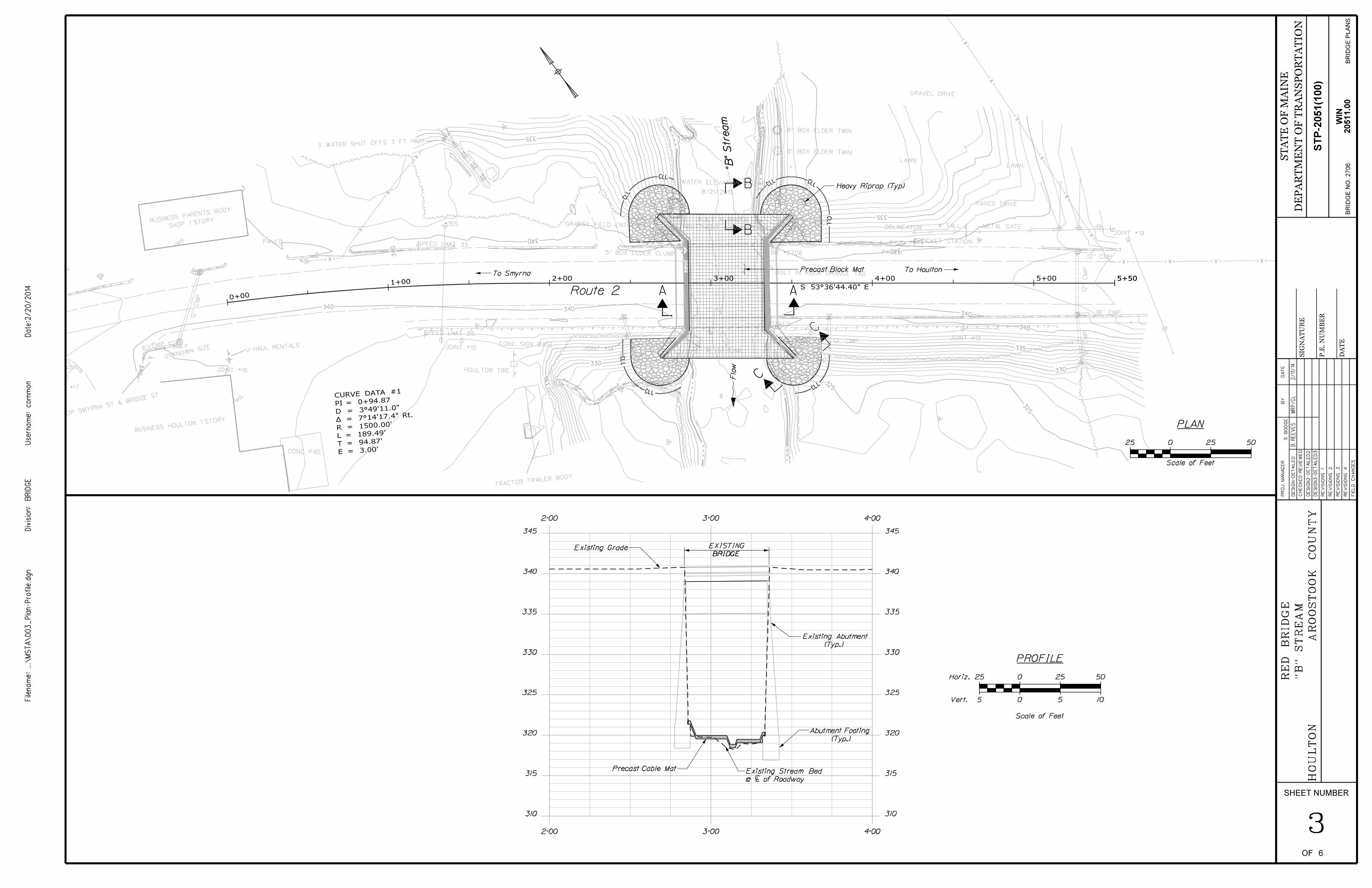
Precast Block Mat
Heavy Riprap (Typ)
To SmyrnaTo Houlton
0+00
1+002+00 3+00 4+00 5+00 5+505+50
E = 3.00’T = 94.87
’L = 189.49
’R = 1500.
00’
PI = 0+94.87CURVE DATA #1
DE
SIG
N-
DE
TAIL
ED
BY
DA
TE
PR
OJ.
MA
NA
GE
R
SHEET NUMBER
FIE
LD
CH
AN
GE
S
RE
VISIO
NS
1
RE
VISIO
NS
2
RE
VISIO
NS
3
RE
VISIO
NS
4
CH
EC
KE
D-
RE
VIE
WE
D
BRID
GE
Divisio
n:
Filena
me:...\
MS
TA\
003
_Pla
n-Profile.d
gn
Userna
me:
Date:2/2
0/2
014
co
mm
on
OF
DE
SIG
N2-
DE
TAIL
ED
2
DE
SIG
N3-
DE
TAIL
ED
3
BRID
GE P
LA
NS
ST
AT
E O
F M
AIN
E
DE
PA
RT
ME
NT O
F T
RA
NSP
OR
TA
TIO
N
DA
TE
SIG
NA
TU
RE
P.E.
NU
MB
ER
RE
D
BRID
GE
HO
UL
TO
N
BRID
GE N
O. 2706
"B" S
TR
EA
M
AR
OO
ST
OO
K
CO
UN
TY
STP-2
051(1
00)
6
3
S.
BO
DG
E
2/11/14
MR
P/
GL
B.
RE
EV
ES
20511.0
0WIN
310
315
320
325
330
335
340
345
310
315
320
325
330
335
340
345
2+00 3+00 4+00
2+00 3+00 4+00
Existing Grade
Scale of Feet
25 0 25 50
5 0 5 10
PROFILE
Horiz.
Vert.
EXISTING
BRIDGE
(Typ.)
Existing Abutment
(Typ.)
Abutment Footing
Precast Cable Mat
@ É of Roadway
Existing Stream Bed
320
320
320
320
325
325
325
325
325
330
330
330
330
330
335
335
335
335
335
335
340
340
340
340
340
340
340 340
340
340
340

DE
SIG
N-
DE
TAIL
ED
BY
DA
TE
PR
OJ.
MA
NA
GE
R
SHEET NUMBER
FIE
LD
CH
AN
GE
S
RE
VISIO
NS
1
RE
VISIO
NS
2
RE
VISIO
NS
3
RE
VISIO
NS
4
CH
EC
KE
D-
RE
VIE
WE
D
BRID
GE
Divisio
n:
Filena
me:...\
004
_C
ounter
measure_
dtl.dgn
Userna
me:
Date:2/2
0/2
014
co
mm
on
OF
DE
SIG
N2-
DE
TAIL
ED
2
DE
SIG
N3-
DE
TAIL
ED
3
BRID
GE P
LA
NS
ST
AT
E O
F M
AIN
E
DE
PA
RT
ME
NT O
F T
RA
NSP
OR
TA
TIO
N
DA
TE
SIG
NA
TU
RE
P.E.
NU
MB
ER
STP-2
051(1
00)
20511.0
0
RE
D
BRID
GE
"B" S
TR
EA
M
HO
UL
TO
NA
RO
OS
TO
OK
CO
UN
TY
BRID
GE N
O. 2706
46
CO
UN
TE
RM
EA
SU
RE
DE
TAIL
SWIN
S.
BO
DG
E
2/11/14
MR
P/
GL
B.
RE
EV
ES
SECTION A-A
Typ.
2
1
needded
Excavate as
Streambed
Existing
necessary streambed excavation)
Fill (Use material from any
3’-0" –
É Channel
1’-0" –
Easterly AbutmentWesterly Abutment
Varies
Special Provision 502
and wingwalls per
along abutment
Must be sealed
Erosion Control Filter Layer
Precast Block Mat
Existing Streambed
SECTION B-B
NOTE: Upstream shown, downstream similar
necessary
Excavation as
Special Provision 502.
in accordance with
shall be anchored
downstream edge
Upstream andErosion Control Filter Layer
Precast Block Mat
SECTION C-C
As shown on plans
Existing Bank
Wrap about Wingwalls
Heavy Riprap
Erosion Control Geotextile
Protective Aggregate Cushion
Erosion Control Filter Layer
Min.
4’-0
"
6"
Min.
Precast Block Mat
5’-0" –
downstream transition of low flow channel to existing streambed shall be as directed by the Resident.
4. For required low flow channel dimensions, see the related countermeasure specification. Upstream and
threaten the stability of the bridge foundations or retaining wall foundations.
countermeasure shall match the existing streambed. The Contractor’s work shall not undermine or otherwise
3. To the maximum extent possible, except to create a low flow channel, the top surface of the scour
2. The thickness of the cable mats shall be 4� inches.
cable mats shall be considered incidental to Item 502.83.
the stone fill. Precast block mats shall bear directly on geotextile fabric. Geotextile fabric under concrete
1. The protective aggregate cushion of the erosion control filter layer shall be six (6) inches thick beneath
NOTES:

DE
SIG
N-
DE
TAIL
ED
BY
DA
TE
PR
OJ.
MA
NA
GE
R
SHEET NUMBER
FIE
LD
CH
AN
GE
S
RE
VISIO
NS
1
RE
VISIO
NS
2
RE
VISIO
NS
3
RE
VISIO
NS
4
CH
EC
KE
D-
RE
VIE
WE
D
BRID
GE
Divisio
n:
Filena
me:...\
BRID
GE\
MS
TA\
005
_Abut
ment.d
gn
Userna
me:
Date:2/2
0/2
014
co
mm
on
OF
DE
SIG
N2-
DE
TAIL
ED
2
DE
SIG
N3-
DE
TAIL
ED
3
BRID
GE P
LA
NS
ST
AT
E O
F M
AIN
E
DE
PA
RT
ME
NT O
F T
RA
NSP
OR
TA
TIO
N
DA
TE
SIG
NA
TU
RE
P.E.
NU
MB
ER
__
__
_
5
STP-2
051(1
00)
20511.0
0
RE
D
BRID
GE
"B" S
TR
EA
M
HO
UL
TO
NA
RO
OS
TO
OK
CO
UN
TY
BRID
GE N
O. 2706
__
__
__
__
__
__
__
__
__
__
__
__
__
__
__
__
__
__
__
__
__
__
__
__
__
__
__
__
__
__
__
__
__
__
__
BJ
R
__
__
__
__
__
__
__
__
__
__
__
__
__
__
__
__
__
__
__
__
__
__
__
__
__
__
__
__
__
__
SD
B
GG
L
WIN
RE
PAIR
DE
TAIL
S
VE
RTIC
AL
SU
RF
AC
E
6
1. The exact dimensions for Repair of Vertical Surfaces shall be determined by the Resident in the field.
NOTES:
14’-0" –
Flow
Top of Abutment Footing
Existing Bridge
Northwest Abutment
Face of Widening
9’-0" –
6’-0"
Vertical Surface
Area for Repair of
3’-0" –
Face of Widening
Vertical Surface
Area for Repair of
3’-0" –
Face of Widening Face of Widening
14’-0" –
Flow
Existing Bridge
3’-0" –
9’-0" –
6’-0"
3’-0" –
Vertical Surface
Area for Repair ofVertical Surface
Area for Repair of
Top of Abutment Footing
Southeast Abutment

NO. GRANTOR INSTRUMENT DATE BOOK PAGE
COUNTY RECORDSHEET NUMBER
OFDATE
COMMISSIONER
CHIEF ENGINEER
REVISIONS
NO. DATE DESCRIPTION BY
SY
MB
OLS
(SE
PTIC T
AN
K)
WA
TE
R LIN
E
GA
S LIN
E
ELE
CT
RIC LIN
E
TE
LE
PH
ON
E LIN
E
SE
WE
R LIN
E
PR
OP
ER
TY LIN
E
EXIS
TIN
G RIG
HT O
F W
AY
CO
NT
RO
L O
F A
CC
ES
S
NE
W RIG
HT O
F W
AY
RIG
HT O
F W
AY M
AP
ST
AT
E O
F M
AIN
E
DE
PA
RT
ME
NT O
F T
RA
NSP
OR
TA
TIO
N
16 S
TA
TE H
OU
SE ST
ATIO
N - A
UG
UST
A, M
E 0
4333-0
016
NE
W R
OW W
ITHIN E
XIS
T.
RO
W
BM
GR
ADIN
G LIM
IT LIN
E
CO
NS
TR
UC
TIO
N LIM
IT LIN
E PL
(WE
LL)
(RO
W M
ON
UM
EN
T)
(TR
AV
ER
SE P
OIN
T)
ITE
MT
EC
HC
HE
CK
ED
BA
SE
MA
P
EXIS
T.
R/
W
PR
OP.
LIN
ES
AR
EA
S
RIGHT-OF-WAY MAP
WIN
SCALE 1"= 25’
PLAN FILED IN PLAN BOOK PAGE
BRID
GE
Divisio
n:
Filena
me:...\
00\
RO
W\
MS
TA\
001_
RW
PL
AN
1.d
gn
Userna
me:
Date:2/2
0/2
014
co
mm
on
S.T.
WW
GG
EE
TT
WE
LL
(IR
ON PIP
E or PIN F
OU
ND)
IPor
IPF
LIM
ITS O
F W
RO
UG
HT P
OR
TIO
N (
L.O.W.P.)
66
20511.00
FEDERAL AID PROJECT NO. STP-2051(100)
HOULTON
HO
ULT
ON
AROOSTOOK COUNTY
DAVID BERNHARDT
JOYCE NOEL TAYLOR
SHEET 1 OF 1
BRIDGE NO. 2706
STATE AID HIGHWAY NO. 23
"B" STREAM
OVER
RED BRIDGE
U.S. ROUTE 2 \ SMYRNA STREET
FEBRUARY 2014
D.O.T. FILE NO. 2-563
Flo
w
0+00
1+00 2+00 3+00 4+00 5+00 5+505+50
PC
=
ST
A.
0+
00.0
0
PT
=
ST
A. 1
+89.49
PO
E
=
ST
A. 5
+50.00
E = 3.00’T = 94.87’L = 189.49’R = 1500.00
’
PI = 0+94.87CURVE DATA #1
GRID 2013
CO
MBIN
ED F
ACT
OR: 0.9
999675
MAIN
E 2000 E
AST Z
ONE
GR
ADIN
G
EA
SE.
EXISTI
NG SLO
PE E
ASE.
NO. 2-144
SEE FILE
SLOPE
EASEMENT
EXISTING
SEE S.H.C. FILE NO. 2-144 (1960)
(DITCH TO STREAM)
S..H.C. FILE NO. 2-144 (1960)
EXISTING DRAINAGE EASE.
EXISTING
EXISTING
EXISTINGSLOPE
SLOPESLOPEEASEMENT
EASEMENT
EASEMENT
SEE S.H.C. FILE NO. 2-144
(1960) SEE S.H.C. FILE NO. 2-144 (1960)
S.H.C. FILE NO. 2-144 (1960)EXISTING DRAINAGE EASE.
GINA L. PARENT
N/F KEVIN E. PARENT
AC
CES
S
EA
SE.T
O
HO
ULT
ON
WA
TE
R
CO.
2607/38
2607/38
GR
ADIN
G
EA
SE.
TO
HO
ULT
ON
WA
TE
R
CO.
SANDRA R. SKEHAN
N/F JOHN R. SKEHAN
P.L.
P.L.
P.L.
P.L.
P.L.
TH
RE
AD
OF S
TR
EA
M
P.L.
TH
RE
AD
OF S
TR
EA
M
JULY 7, 1960
VOL. 16 PG. 86SMYRNA STREETSTREET WIDENING FORSEE SURVEY PLAN OF
S.H.C. FILE NO. 2-144 (1960)EXISTING DRAINAGE EASE.
+40
EASE.
LIMITS
+05*
+50
+75
65’
SLOPE
EASE. LIMIT
S75’
52’*
57’*
+50+75 +85
SLO
PE
EASE.
LIMIT
S
SL
OPE
+35
65’
70’
47’*
47’*
+20
70’
60’
46’*
TE
MP.
TEMP.CONST.CONST.
LIMITS
LIMIT
S
+03*
+04*
TE
MP.
CONST. CONST.LIMITS
LI
MITS
TEMP.
+15*
+17*
ï »¿0.05î�
ï »¿0.09î �ï »¿0.15î �
ï »¿0.11î �
ï »¿1340î��
ï »¿691î��
TOTAL AREA = 3.4* AC. (PER TOWN)
TEMP. CONST. RIGHTS = 0.11* AC. (1)
SLOPE EASE. = 691* S.F. (1)
ITEM NO. (1)
M T TIRE, INC.
ï »¿893î��
TOTAL AREA = 3* AC. (PER TOWN)
TEMP. CONST. RIGHTS = 0.15* AC. (1)
SLOPE EASE. = 893* S.F. (1)
ITEM NO. (3)
HOULTON WATER COMPANY
P.L.
B.L.
BEGIN
B.L.
END
360.51’
D.O.T. FILE NO. 2-387 (M.D.O.T. AUGUSTA OFFICE- NOT RECORDED)S.H.C. FILE NO. 2-144
SEE ALSO:
1843 4 RODS WIDE
VOL. 1 PG. 125
COMMISSIONER RECORDS
AROOSTOOK COUNTY
R/W REFERENCES
BRID
GE S
TR
EE
T
U.S. ROUTE 2
TO SMYRNA TO HOULTON
"B" S
TR
EA
M
"B" S
TR
EA
M
SMYRNA STREET
S.A. HIGHWAY NO. 23S 53°-36’-44.4" E
TOTAL AREA = 1.50* AC. (PER TOWN)
TEMP. CONST. RIGHTS = 0.09 * AC. (1)
SLOPE EASE. = 0.05* AC. (1)
ITEM NO. (2)
JOHN R. SKEHAN
TOTAL AREA = 1.05* AC. (PER TOWN)
TEMP. CONST. RIGHTS = 1340* S.F. (1)
ITEM NO. (4)
TOWN OF HOULTON
Sill E
L
Sill E
L
WPAVED
U-HAUL RENTALS6" CMP
PAVED
METAL GATE
JOINT #15
TRACTOR TRAILER BODY
JOINT #17
12" CMP
BUSINESS HOULTON 1 STORY
WATER ELEVATION 320.48’
8/21/2013
#17S
4’ TALLDELINEATOR
#15S
JOINT #13
12"
CM
P
12" CMP
CROCKET STATIONSPEED LIMIT 35
JOINT #12CONC. SIGN BASE 12" CMP
SPEED LIMIT 25
LAWN
#84A
5" BOX ELDER CLUMP
10" BIRCH
CONC. PAD
18" CMP
STOP SMYRNA ST & B
RIDGE ST
JOINT #14
8" BOX ELDER TWIN
PAVED
BR #2706
GRAVEL DRIVE
JOINT #19
LAWN
JOINT #16
8" BOX ELDER TWIN
UNKNOWN SIZE
GRASSY FIELD ENTRANCE
HOULTON TIRE
PAVED DRIVE
12"
CM
PBOLT IN ROCK ORANGE TAG
"B" STREAM
3 WATER SHUT OFFS 3 FT HIGH
ABUTTMENT ORANGE TAG
BOLT IN BRIDGESHOP 1 STORYBUSINESS PARENTS BODY
18"
CM
P

![Internal - Luciano Chinellato · AnyOne® Internal è -P_[\YL 3L]LS 7YVZ[OLZPZ EZ Post Milling Abutment Angled Abutment CCM Abutment Temporary Abutment [Titanium] Temporary Abutment](https://static.fdocuments.us/doc/165x107/5c038f7909d3f2156d8cd7fd/internal-luciano-anyone-internal-e-pyl-3lls-7yvzolzpz-ez-post-milling.jpg)


![COFFERDAM [Compatibility Mode]](https://static.fdocuments.us/doc/165x107/577cdecf1a28ab9e78afe28b/cofferdam-compatibility-mode.jpg)