![OverFeat: Integrated Recognition, Localization and ... · arXiv:1312.6229v4 [cs.CV] 24 Feb 2014 OverFeat: Integrated Recognition, Localization and Detection using Convolutional Networks](https://static.fdocuments.us/doc/165x107/5b7c76697f8b9a184a8e7a98/overfeat-integrated-recognition-localization-and-arxiv13126229v4-cscv.jpg)
An Overview on Integrated Localization and Communication ... · An Overview on Integrated...
35
1 An Overview on Integrated Localization and Communication Towards 6G Zhiqiang Xiao and Yong Zeng, Member, IEEE Abstract—While the fifth generation (5G) cellular system is being deployed worldwide, researchers have started the investiga- tion of the sixth generation (6G) mobile communication networks. Although the essential requirements and key usage scenarios of 6G are yet to be defined, it is believed that 6G should be able to provide intelligent and ubiquitous wireless connectivity with Terabits per second (Tbps) data rate and sub-millisecond (sub-ms) latency over three-dimensional (3D) network coverage. To achieve such goals, acquiring accurate location information of the mobile terminals is becoming extremely useful, not only for location-based services but also for improving wireless communication performance in various ways such as channel estimation, beam alignment, medium access control, routing, and network optimization. On the other hand, the advancement of communication technologies also brings new opportunities to greatly improve the localization performance, as exemplified by the anticipated centimeter-level localization accuracy in 6G by ultra massive MIMO (multiple-input multiple-output) and millimeter wave (mmWave) technologies. In this regard, a unified study on integrated localization and communication (ILAC) is necessary to unlock the full potential of wireless networks for the best utilization of network infrastructure and radio resources for dual purposes. While there are extensive literatures on wireless localization or communications separately, the research on ILAC is still in its infancy. Therefore, this article aims to give a tutorial overview on ILAC towards 6G wireless networks. After a holistic survey on wireless localization basics, we present the state-of- the-art results on how wireless localization and communication inter-play with each other in various network layers, together with the main architectures and techniques for localization and communication co-design in current two-dimensional (2D) and future 3D networks with aerial-ground integration. Finally, we outline some promising future research directions for ILAC. Index Terms—Wireless localization, integrated localization and communication, cellular networks, B5G, 6G I. I NTRODUCTION Starting from the second generation (2G), wireless local- ization has been included as a compulsory feature in the standardization and implementation of cellular networks, with continuous enhancement on the localization accuracy over each generation, e.g., from hundreds of meters accuracy in 2G to tens of meters in the fourth generation (4G). For the forthcoming fifth generation (5G) mobile networks, lo- calization is regarded as one of the key components, due to its fundamental support for various location-based services, and the requirement on localization accuracy is up to sub- meter level [1]. The availability of accurate real-time location Z. Xiao and Y. Zeng are with the National Mobile Communications Research Laboratory, Southeast University, Nanjing 210096, China. Y. Zeng is also with the Purple Mountain Laboratories, Nanjing 211111, China (e-mail: zhiqiang [email protected], yong [email protected]). information of mobile terminals is expected to play an in- creasingly important role in future wireless networks. While the deployment of 5G networks is ongoing, researchers around the world have already started the investigation on the sixth generation (6G) mobile communication targeting for network 2030, with various visions proposed [2]–[7]. For example, it was envisioned that 6G should achieve “ubiquitous wireless intelligence” [5], for providing users smart context-aware services through wireless connectivity anywhere in the world. This renders that acquiring the accurate real-time location information of users becomes more critical than ever before, with potentially centimeter-level localization accuracy for 6G. However, most current localization services provided by global navigation satellites systems (GNSS), wireless local area networks (WLAN) or cellular networks can at best achieve meter-level localization accuracy in clutter envi- ronments. Such coarse localization services are difficult to meet the centimeter-level localization accuracy requirements of many emerging applications. For example, the following three promising usage scenarios of 5G-and-beyond networks, namely, intelligent interactive networks, smart city, and au- tomatic factory, all highlight the critical role of accurate localization in future network design. a) Intelligent Interactive Networks: It is believed that the ultimate goal of communication networks is to promote the intelligent interactions across the world, in terms of people- to-people, people-to-machine, and machine-to-machine. An unprecedented proliferation of new internet-of-things (IoT) services, like multisensory extended reality (XR) encompass- ing augmented/mixed/virtual reality (AR/MR/VR) [8], brain- computer interfaces (BCI) [3], as well as tele-presence and tele-control services [5], brings excellent opportunities to realize the goal of interaction with everything. To implement such new applications, it is necessary to achieve the high localization performance, as elaborated in the following. • Multisensory XR: XR services will enable users to experience and interact with virtual and immersive en- vironments through first-person view [8]. To enable truly immersive XR applications, it must deploy XR systems through wireless networks, and thus the tracking accuracy of XR devices is of paramount importance. For wireless XR applications, a control center collects the tracking information of the XR devices, and sends data to those devices through wireless links. Therefore, the accuracy of device tracking and the delay of signal measurements will significantly affect the XR information transmission and hence impact the user experience. For instance, an inaccurate head-tracking may cause cybersickness, like arXiv:2006.01535v1 [eess.SP] 2 Jun 2020
Transcript of An Overview on Integrated Localization and Communication ... · An Overview on Integrated...

1
An Overview on Integrated Localization andCommunication Towards 6G
Zhiqiang Xiao and Yong Zeng, Member, IEEE
Abstract—While the fifth generation (5G) cellular system isbeing deployed worldwide, researchers have started the investiga-tion of the sixth generation (6G) mobile communication networks.Although the essential requirements and key usage scenariosof 6G are yet to be defined, it is believed that 6G should beable to provide intelligent and ubiquitous wireless connectivitywith Terabits per second (Tbps) data rate and sub-millisecond(sub-ms) latency over three-dimensional (3D) network coverage.To achieve such goals, acquiring accurate location informationof the mobile terminals is becoming extremely useful, notonly for location-based services but also for improving wirelesscommunication performance in various ways such as channelestimation, beam alignment, medium access control, routing,and network optimization. On the other hand, the advancementof communication technologies also brings new opportunitiesto greatly improve the localization performance, as exemplifiedby the anticipated centimeter-level localization accuracy in 6Gby ultra massive MIMO (multiple-input multiple-output) andmillimeter wave (mmWave) technologies. In this regard, a unifiedstudy on integrated localization and communication (ILAC) isnecessary to unlock the full potential of wireless networks for thebest utilization of network infrastructure and radio resources fordual purposes. While there are extensive literatures on wirelesslocalization or communications separately, the research on ILACis still in its infancy. Therefore, this article aims to give a tutorialoverview on ILAC towards 6G wireless networks. After a holisticsurvey on wireless localization basics, we present the state-of-the-art results on how wireless localization and communicationinter-play with each other in various network layers, togetherwith the main architectures and techniques for localization andcommunication co-design in current two-dimensional (2D) andfuture 3D networks with aerial-ground integration. Finally, weoutline some promising future research directions for ILAC.
Index Terms—Wireless localization, integrated localization andcommunication, cellular networks, B5G, 6G
I. INTRODUCTION
Starting from the second generation (2G), wireless local-ization has been included as a compulsory feature in thestandardization and implementation of cellular networks, withcontinuous enhancement on the localization accuracy overeach generation, e.g., from hundreds of meters accuracy in2G to tens of meters in the fourth generation (4G). Forthe forthcoming fifth generation (5G) mobile networks, lo-calization is regarded as one of the key components, due toits fundamental support for various location-based services,and the requirement on localization accuracy is up to sub-meter level [1]. The availability of accurate real-time location
Z. Xiao and Y. Zeng are with the National Mobile CommunicationsResearch Laboratory, Southeast University, Nanjing 210096, China. Y. Zeng isalso with the Purple Mountain Laboratories, Nanjing 211111, China (e-mail:zhiqiang [email protected], yong [email protected]).
information of mobile terminals is expected to play an in-creasingly important role in future wireless networks. Whilethe deployment of 5G networks is ongoing, researchers aroundthe world have already started the investigation on the sixthgeneration (6G) mobile communication targeting for network2030, with various visions proposed [2]–[7]. For example, itwas envisioned that 6G should achieve “ubiquitous wirelessintelligence” [5], for providing users smart context-awareservices through wireless connectivity anywhere in the world.This renders that acquiring the accurate real-time locationinformation of users becomes more critical than ever before,with potentially centimeter-level localization accuracy for 6G.
However, most current localization services provided byglobal navigation satellites systems (GNSS), wireless localarea networks (WLAN) or cellular networks can at bestachieve meter-level localization accuracy in clutter envi-ronments. Such coarse localization services are difficult tomeet the centimeter-level localization accuracy requirementsof many emerging applications. For example, the followingthree promising usage scenarios of 5G-and-beyond networks,namely, intelligent interactive networks, smart city, and au-tomatic factory, all highlight the critical role of accuratelocalization in future network design.
a) Intelligent Interactive Networks: It is believed that theultimate goal of communication networks is to promote theintelligent interactions across the world, in terms of people-to-people, people-to-machine, and machine-to-machine. Anunprecedented proliferation of new internet-of-things (IoT)services, like multisensory extended reality (XR) encompass-ing augmented/mixed/virtual reality (AR/MR/VR) [8], brain-computer interfaces (BCI) [3], as well as tele-presence andtele-control services [5], brings excellent opportunities torealize the goal of interaction with everything. To implementsuch new applications, it is necessary to achieve the highlocalization performance, as elaborated in the following.• Multisensory XR: XR services will enable users to
experience and interact with virtual and immersive en-vironments through first-person view [8]. To enable trulyimmersive XR applications, it must deploy XR systemsthrough wireless networks, and thus the tracking accuracyof XR devices is of paramount importance. For wirelessXR applications, a control center collects the trackinginformation of the XR devices, and sends data to thosedevices through wireless links. Therefore, the accuracyof device tracking and the delay of signal measurementswill significantly affect the XR information transmissionand hence impact the user experience. For instance, aninaccurate head-tracking may cause cybersickness, like
arX
iv:2
006.
0153
5v1
[ee
ss.S
P] 2
Jun
202
0

2
nausea, disorientation, headaches, and eye strain [9]. Ingeneral, for XR services, depending on the usage scenar-ios, the requirement for localization accuracy ranges from1 centimeter (cm) to 10 cm, and the time delay shouldbe typically less than 20 milliseconds (ms) [8].
• Wireless BCI (WBCI): The forthcoming 5G and future6G networks bring new opportunities to tailor commu-nication networks into the versatile networks integratedwith human-centric communication, wireless sensing, andremote control [3], where people will be enabled tointeract with their surrounding environment using variousIoT devices connected through the WBCI technology. Itopens the door for people to control their neighboring IoTdevices through their brain implants, gestures, empathicas well as haptic messages [8]. Such a breathtaking tech-nology requires the communication services of extremelyhigh data rate, ultra-low latency, and high reliability, aswell as the localization support of high accuracy, e.g.,centimeter-level accuracy. In addition, the cooperativelocalization among IoT devices is also quite importantfor WBCI.
• Tele-presentation and Tele-control: With the advance-ment of various supporting technologies including high-resolution imaging and sensing, wearable displays, mo-bile robots and drones, it is expected that the technologiesof tele-presentation and tele-control will become realityin the near future [5]. For tele-presentation, a remoteenvironment can be represented through real-time envi-ronment capturing, information transmission, and three-dimensional (3D) holographic rendering, which makesthe accurate location information critical for 3D mapping.Furthermore, people may operate the remote IoT devicesthrough wireless networks, just like manipulating themface-to-face, which is referred to as tele-control or tele-operation. An exemplary application of tele-presentationand tele-control is the tele-surgery, which will enabledoctors to perform emergent surgery remotely. Note thatin such use cases, highly-accurate, ultra-reliable, andlow-latency localization is vital. For tele-control, theremote and neighboring localization systems usually havetwo separate coordinates, perform different localizationalgorithms, and use different reference nodes, which maycause mismatch errors. Therefore, for such applications,the real-time infrastructure calibration between the twolocalization systems is of paramount importance for re-ducing the mismatch errors.
b) Smart City: A smart city has the ability to efficientlyanalyze different requirements from the society, and reason-ably manage and optimize public resources, such as electricity,water, transportation, and healthcare, to provide better publicservices [10]. A truly smart city entails many different aspects.Here, we elaborate two major application scenarios to outlinethe importance of the accurate localization for smart city:
• Smart Indoor Services: Over the last decade, IoTtechnology has developed rapidly, which will flourishthe smart indoor services, like smart homes, indoornavigation in shopping malls, and crowd monitoring.
Different from outdoor scenarios, one critical issue of in-door localization is the severe non-light-of-sight (NLoS)signal propagation that may significantly degrade thelocalization accuracy [11], [12]. Meanwhile, the privacyprotection of location information is another critical issuefor public indoor localization services [5]. One of the keyproblems is to identify what kind of location informationneeds to be protected. For example, for some publicdevices, their location information should be accessibleto all user devices, while that for user personal devicesor some kernel public devices needs to be protected.
• Smart Transportation: The research on smart trans-portation is still ongoing, with several standards proposed,like dedicated short-range communications (DSRC) [13]and vehicle-to-everything (V2X) [14]. The autonomousdriving [15] and vehicle-to-vehicle (V2V) communica-tions [16] are envisioned as two attractive developingtrends of smart transportation, both of which call foradvanced localization technologies. For autonomous driv-ing, the 3D mapping for the real-time scenarios is critical,which requires the accurate relative distances betweenthe vehicle and obstacles to construct the environmentmodel. The V2V communications also need accuratelocalization to improve the communication performance.Compared with other use cases, for smart transportation,the localization systems should be designed not only forhigh accuracy, but also for wide coverage, as well as forrobustness in highly mobile scenarios.c) Automatic Factory: The development of connected
robotics and autonomous systems (CRAS) like autonomousrobotics, drone-delivery systems, etc., promotes the progressof automatic factory [3], such as smart storage, autonomousproduction, and autonomous delivery. The accurate localiza-tion of various IoT devices is a prerequisite to enable effectivecooperation among them. Different from other applications,for automatic factory, cooperative localization among massiveIoT devices is of critical importance, which will requirethe highly-accurate, low-latency, and highly-reliable locationinformation of the massive devices to build the end-to-end(E2E) communication links.
Table I summarizes the main localization requirements ofdifferent applications for 5G/6G networks. It is observedthat achieving highly-accurate, low-latency, and highly-reliablelocalization will play an important role in future wirelessnetworks. Furthermore, one promising development trend offuture networks is to integrate communication, computing,control, localization, and sensing (3CLS) [3], and further builda self-sustaining networks (SSN) that can maintain the keyperformance indicators (KPIs) by appropriately managing theradio resources according to the real-time locations of mobileterminals.
To achieve the above goals, the underlying technologies of5G-and-beyond mobile communication, like millimeter wave(mmWave), massive MIMO (multiple-input multiple-output),and ultra dense networks (UDNs), can be utilized for improv-ing the localization performance. The mmWave signal withbandwidth up to 2 GHz and center frequencies around 30 GHzand above can provide much higher temporal resolutions for

3
TABLE ITHE LOCALIZATION REQUIREMENTS OF DIFFERENT APPLICATIONS FOR 5G/6G NETWORKS
Applications Requirements
Intelligent Interactive NetworkMultisensory XR Centimeter-level accuracy (i.e. 1-10 cm);
Low latency (less than 20 ms).
WBCICentimeter-level accuracy;Low latency (millisecond-level);High requirements on cooperative localization among IoT devices.
Tele-presentation and Tele-controlCentimeter-level accuracy;High reliability;Calibration between two different localization systems.
Smart City Smart Indoor Services NLoS-based localization;Privacy information classification and protection.
Smart Transportation
Submeter-level localization;Wide coverage;High mobility tracking;Cooperative localization in V2X communication cases.
Automatic Factory CRAS
Cooperative localization among massive IoT devices;At least submeter-level accuracy;High reliability;Low latency.
improving time-based localization [17]. Furthermore, the ultramassive antenna arrays consisting of thousands of antennaelements can bring the angular resolution less than 1 degreefor angular-based localization [18]. Besides, the UDNs canincrease the likelihood of light-of-sight (LoS) links, whichcan also be exploited for improving localization performance[17]. On the other hand, the location information of mobileterminals can be used for assisting communications, likelocation-aided channel estimation, beam alignment, routing,and network optimization. Furthermore, a unified design onsignal waveforms, coding, modulation, and radio resourceallocation for the seamless integration of localization and com-munication can be pursued, and the promising new paradigmis referred to as integrated localization and communication(ILAC).
While there are extensive literatures focusing on wirelesslocalizations [19]–[26], or communications alone, to our bestknowledge, a tutorial overview on ILAC to fully utilize thenetwork infrastructure and radio resources for dual purposesis still missing. In [19]–[21], the authors provide surveyson indoor localization. In [19], the authors focused on theprinciples of different localization approaches and providedan overview on various localization infrastructures. In [20],the advanced techniques, such as data fusion, cooperativelocalization, and game theory, were highlighted to improvethe localization performance. In [21], the authors providedan up-to-date overview on indoor localization with emphasison IoT scenarios. In [22] and [23], the surveys of enablingtechnologies for network localization, tracking and navigationwere given. In [22], the authors mainly focused on the math-ematical theories of different indoor tracking and mappingmethods. In [23], a comprehensive review on localizationtechniques in cellular network, WLAN, and wireless sensornetworks (WSNs) was provided. In [24] and [25], the authorssummarized the localization techniques from signal processingperspective. In [26], a survey of cellular-based localizationwas given, where the evolution of the conventional cellularlocalization methods were given, together with the envisionon the 5G new radio (NR) localization.
In this article, we aim to provide a tutorial overviewon ILAC towards 6G. To this end, we first give a holisticintroduction on wireless localization basics, in terms of themain definitions and classifications of localization systems,different localization approaches, fundamental performanceanalysis and metrics, the major localization infrastructures,and some advanced localization related techniques. Then wefocus on the ILAC targeting for the future wireless networkdesign. To this end, we first provide an overview on therecent recommendations of the third generation partnershipproject (3GPP) for 5G localization, and then discuss theenabling technologies of 5G networks towards centimeter-level localization accuracy. After that, we present the state-of-the-art location-aided communication to expose how wirelesslocalization and communication inter-play with each otherin different network layers, and give some initial studies onlocalization and communication co-design with best utilizationof the network infrastructures and radio resources to unlockthe full potential of the wireless networks. Furthermore, adiscussion on ILAC for aerial-ground integrated networks willbe given, which aims to facilitate the ubiquitous wirelesscoverage, moving from the conventional two-dimensional (2D)plane to the 3D space. Finally, we give an architecture of fu-ture wireless networks, and discuss the enabling technologiesand challenges, attempting to outline some promising futureresearch directions for ILAC.
II. WIRELESS LOCALIZATION BASICS
A. Definition and Classification of Wireless Localization
As illustrated in Fig. 1, a wireless localization system aimsto estimate the location of the targeting object based on a setof wireless reference signals propagated between the referencenodes and the targeting object. The localization functions canbe deployed based on either the existing wireless commu-nication systems, such as cellular networks and WLAN, ordedicated infrastructures, like GNSS. The targeting object withits unknown location to be localized is often referred to asagent node or mobile user, and the reference nodes with knownlocations are often called as anchor nodes (ANs) or landmarks

4
Fig. 1. A general architecture of wireless localization, with heterogeneouswireless infrastructures including cellular networks, navigation satellites, andWLAN.
[22]. For convenience, throughout this paper, we use the termsagent node and ANs to represent the targeting object andreference nodes, respectively, as shown in Fig. 1. Comparedto a closely related terminology, wireless positioning, whichestimates the position of the agent node relative to the ANs,wireless localization further locates the estimated positionon a coordinate of a map based the locations of the ANs.Nonetheless, the terminologies positioning and localization areoften used interchangeably [26].
Typically, a wireless localization system consists of twomajor components: a set of ANs and a location estimationunit that can be deployed either on the agent node itselfor on a remote site. The procedures of localization usuallyinclude two stages. In the first stage, specific reference signalsare transmitted either by the ANs or the agent node, whichare measured by the other end of the link to obtain somelocation-related information, such as received signal strength(RSS), time of arrival (TOA), time difference of arrival(TDOA), or angle of arrival (AOA) of the received signal.In the second stage, such measurements are collected at thelocation estimation unit to estimate the location of the agentnode. Localization systems can be categorized from variousperspectives, like based on location estimation algorithms [23]or localization infrastructures [20]. One popular classificationis to consider where the location estimation is performed[27], based on which we have self-localization or remotelocalization systems.
1) Self-Localization: As illustrated in Fig. 2(a), for self-localization systems, a location estimation unit is deployed onthe agent node, which receives reference signals transmittedfrom several ANs. The agent node has the capability to per-form appropriate signal measurements, based on which its ownlocation is estimated. Self-localization systems have severaladvantages. First, since almost all localization-relevant opera-tions are performed locally at the agent node, the localizationspeed is mainly dependent on the computational capabilityof the agent node. Therefore, such systems are easier forperformance improvement via updating the computational ormeasurement units of the agent node, without having to modifythe network infrastructure. Second, self-localization systemshave the inherent mechanism for user privacy protection, sincethe agent node only passively receives signals transmitted from
(a) Self-localization system
(b) Remote localization system
Fig. 2. An illustration of self-localization and remote localization systems.(a) For self-localization, the location estimation is performed by the agentnode itself. (b) For remote localization, the location estimation is performedby a remote central station.
ANs, with little risk of location information leakage from theuser side. Finally, for some dynamic localization scenarioslike tracking and navigation, various onboard sensors likeinertial measurement units (IMUs) can be handily equippedon the agent node to provide some motion information, whichcan be utilized to further enhance the localization accuracy[24]. However, self-localization systems have high hardwarerequirements on the agent node, such as high caching and com-putational capability, to accomplish the tasks of signal mea-surements and location estimation by itself. The consequenceis that such systems, like global positioning system (GPS) orinertial navigation system (INS), can only be deployed on thedevices with powerful computational components.
2) Remote Localization: For remote localization systems,as illustrated in Fig. 2(b), the reference signals are transmittedfrom the agent node to ANs. Upon receiving the referencesignals, the ANs would send their respective signal mea-surements to a remote central station, where the locationestimation is performed. The main advantage of remote lo-calization systems over the self-localization counterparts isthe less demanding on the agent node, since almost all time-consuming and complex computing operations are performedat the remote central station, such as cellular base stations(BSs) or computing center. Therefore, remote localization isespecially appealling for resource-limited devices, such as IoTdevices and wireless sensor nodes. In addition, different fromself-localization systems where the location information isonly acquired by the agent node itself, remote localizationsystems can preserve locations for all agent nodes in the

5
area of interest, which can be utilized for various purposes,like location-aware communication [28]. However, since alllocation information of agent nodes are stored in a remoteserver, the information privacy and security is a critical issuefor remote localization.
B. Basic Localization Techniques
In general, localization techniques can be classified into twomain categories: direct localization and two-step localization.For direct localization [29]–[31], the received signals are di-rectly used to estimate the location of the agent node, whereasfor two-step localization, the location-related information, suchas RSS, TOA, TDOA and AOA, is firstly extracted from thereceived signals, based on which the location of the agentnode is estimated. Note that in principle, direct localizationcan achieve better performance than two-step localization.However, by considering the complexity and implementationconstraints, two-step localization approaches are usually usedin practical systems. Therefore, in this article, we will fo-cus on two-step localization approaches. Typically, dependingon the different principles behind, the two-step localizationapproaches can be further classified into geometric-based,scene analysis (also known as fingerprinting), and proximityapproaches [19], [32], as discussed in details in the following.
Consider a basic wireless localization system consisting ofN ANs and one agent node. The locations of the ANs areknown, denoted by pn, n = 1, · · · , N , while that of the agentnode needs to be estimated, denoted by w. Regardless of self-or remote localization, a two-step localization approach can beinterpreted as a parameters estimation problem. For the firststep for signal measurement, the location-related informationis obtained from the received signals, which are in generalaffected by multi-path effects and NLoS propagation, and ageneral measurement model can be expressed as
rn = h(pn,w) + en, n = 1, 2, · · · , N, (1)
where rn denotes the generic signal measurement associatedwith the nth AN, h(·) is a nonlinear function which containsall necessary information to compute the location of the agentnode, and en represents the measurement error. Note that theexact expressions of h (·) for geometric-based methods canbe easily established (as given in the subsequent subsections)since there are clear algebraic relationships between ANs andthe agent node, while that for fingerprinting-based methods donot exist, and the pre-built fingerprints are usually treated ash (·). For the second step for location estimation, the main taskis to solve the systems of nonlinear equations in (1) to esti-mate w based on the obtained signal measurements {rn}Nn=1.Such nonlinear equations are difficult to solve directly anddeserve detailed discussions. Therefore, in this subsection, wemainly focus on the principles and characteristics of differentmeasurement models, while a comprehensive analysis aboutthe location estimators to solve those nonlinear equations isdeferred to Section II-C.
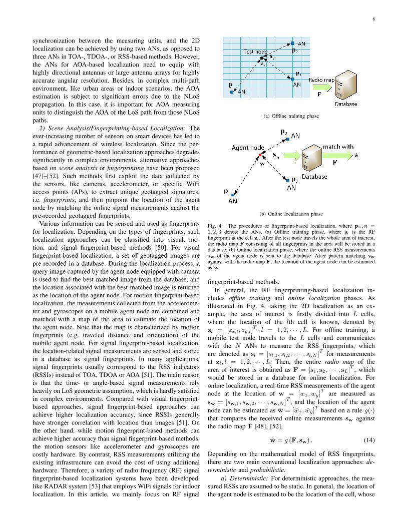
1) Geometric-Based Localization: As illustrated in Fig. 3,geometric-based localization technologies exploit the geomet-ric properties of triangles to locate the agent node. Typically,
(a) RSS- or TOA-based localization
(b) TDOA-based localization
(c) AOA-based localization
Fig. 3. Geometric-based localization in 2D space with perfect signal mea-surements, where pn ∈ R2×1, n = 1, 2, 3, denote the ANs, w ∈ R2×1
is the agent node to be located. (a) RSS- or TOA-based localization, wheredn, n = 1, 2, 3, denote the actual distances between the agent node to thethree ANs. (b) TDOA-based localization, where dn,1, n = 2, 3, represent therelative distance between a pair of ANs to the agent node. The two pairsof red and black lines correspond to the hyperbola curves. (c) AOA-basedlocalization, where θi, i = 1, 2 are the angles between the ANs and the agentnode.
geometric-based methods have two variations: trilaterationand triangulation. Trilateration determines the location of theagent node using the distance-related signal measurementsfrom multiple ANs, so it is also called ranging. For example,in 2D localization scenarios, the agent node would be ideallylocated at the intersection of at least three circles with centersbeing the locations of the ANs and radii equal to the distancesfrom the agent node to each of the ANs. The locations of theANs are known and their distances to the agent node can be de-rived from RSSs [33]–[35], TOAs [36]–[40] or TDOAs [41]–[43] of the received signals. On the other hand, triangulationusually measures the AOAs of the received signals propagatedbetween the ANs and the agent node, and locates the agentnode at the intersection of angle direction lines [44], [45],where the AOAs can be measured with the aid of directional
6
antennas or antenna arrays deployed on the agent node or theANs. Different from trilateration which requires at least threeANs, two ANs are sufficient for triangulation to locate theagent node in a 2D space.
a) RSS: RSS-based localization approaches use the av-erage power attenuation of the signals propagated between theANs and the agent node to estimate their distances, based onwhich a geometric model is formulated to estimate the locationof the agent node [33]–[35]. For example, as illustrated in Fig.3(a), the location of an agent node can be ideally determinedin 2D space with the use of three ANs. In general, theaverage received power Pr,n associated with the nth AN canbe modelled in dB form as [46]
Pr,n = P0 − 10αn log10 dn + eRSS,n, n = 1, 2 · · · , N, (2)
where P0 is the reference received average power at a refer-ence distance of 1 meter (m), dn = ‖pn −w‖ is the actualdistance between the nth AN and the agent node, αn denotesthe path loss exponent, and eRSS,n represents the error of theRSS measurement. Assuming that P0 and αn, n = 1, 2, · · · , Nare known, the distance between the agent node and each of theANs can be estimated. Specifically, let rRSS,n = Pr,n−P0 andhRSS(pn,w) = −10αn log10 dn = −10αn log10 (‖pn −w‖).The generic model in (1) for RSS-based localization can thusbe written as
rRSS,n = hRSS(pn,w) + eRSS,n, n = 1, 2, · · · , N. (3)
The remaining task of the RSS-based localization is to esti-mate w based on the obtained {rRSS,n}Nn=1 in (3), which isdiscussed in Section II-C.
The main advantage of RSS-based localization lies in thattime synchronization among different nodes are not neededand RSS measurements are readily available for almost allpractical wireless systems. In addition, different from alter-native schemes like TOA, TDOA, or AOA-based approaches,RSS measurements do not rely on LoS signal propagation.However, the main drawback of RSS-based approaches is thepoor localization accuracy, especially in clutter environments,since the signal attenuation in these environments is onlyweakly correlated with distance, leading to poor accuracy fordistance estimation [33]. Besides, an accurate signal prop-agation model is necessary for reliable RSS-based distanceestimation, which is challenging due to the unpredictablevariations of the channel behavior. Therefore, in practice, RSS-based localization is mostly adopted for those applicationswith coarse localization accuracy requirements.
b) TOA: As illustrated in Fig. 3(a), TOA-based ap-proaches first estimate the distances between the agent nodeand each of the ANs by using the signal propagation delayor time of flight (TOF), denoted by τf, and then build thetrilateration model to estimate the location of the agent node[36]–[40]. Typically, depending on how τf is defined, TOA-based methods can be further divided into one-way TOA (OW-TOA) [39] and two-way TOA (TW-TOA) [40].
For OW-TOA localization, node A (either the AN or theagent node) transmits to node B a packet that contains atimestamp τs recording the time when the packet was sent, andnode B then measures the TOA of the received signal, denoted
by τr. The TOA is commonly measured by using matched fil-tering or correlation techniques, where the TOA measurementis given by the time shift of the reference signal that yieldsthe maximum correlation value with the received signals. ForOW-TOA localization, if the time clock between the ANs andthe agent node are perfectly synchronized, it is clear that τfcan be determined by node B as τf = τr−τs, and the distancebetween node A and node B can be calculated as d = τf · c,where c is the signal propagation speed, which is typicallytaken as the light speed. However, OW-TOA methods havetwo main drawbacks. First, a small time synchronization errorbetween the agent node and ANs can significantly compromisethe distance estimation. Second, the transmitted signal mustbe labeled with a timestamp to allow the receiving node tocalculate τf, which increases the complexity of the transmittedsignals’ structures and may cause additional estimation error.
On the other hand, for TW-TOA localization, node Atransmits a packet to node B, which responds by sending anacknowledgement packet to node A after a response delayτd. Provided that τd is known, node A can calculate itsdistance to node B based on the signal round-trip time offlight (RTOF), i.e. τRT = 2τf + τd. TW-TOA addresses thefirst drawback of OW-TOA by avoiding the requirement oftime synchronization between the two nodes. However, inpractice, it is still difficult for the measurement node, i.e. nodeA, to know the exact response delay τd. Although τd could beignored if it is relative small compared with τf in long-rangesignal propagation, it critically affects the performance forshort-range scenarios. Furthermore, while TW-TOA methodeliminates clock synchronization error between the two nodes,relative clock drift could compromise the distance estimationaccuracy. In addition, timestamp is still needed for TW-TOAto compute the RTOF of the transmitted signal.
Mathematically, a general TOA-based measurement modelis formulated as [36], [38]
c · τf,n = dn + eTOA,n, n = 1, 2, · · · , N, (4)
where τf,n is the measured TOF of signal propagation betweenthe nth AN and the agent node, which is typically affected bypositive bias errors introduced in the process of signal mea-surement, as captured by the additional the measurement erroreTOA,n. Following similar notations in (3), let rTOA,n = c · τf,nand hTOA(pn,w) = dn = ‖pn −w‖, the generic model in(1) for TOA-based localization can be written as
rTOA,n = hTOA(pn,w) + eTOA,n, n = 1, 2, · · · , N. (5)
By solving systems of nonlinear equations in (5), the locationof the agent node can be estimated.
c) TDOA: TDOA refers to as the difference on the TOAsof the received signals at two different measurement units[41]–[43]. Compared with TOA-based methods that estimatethe absolute distances between each AN and the agent node,TDOA-based methods estimate the relative distance between apair of ANs to the agent node. For each TDOA measurements,the agent node would lie on a hyperboloid with a constantdistance difference between a pair of ANs to the agent node.Specifically, the equation of the hyperboloid is given by [19]
di,j = ‖pi −w‖ − ‖pj −w‖ , i 6= j, (6)

7
where di,j denotes the relative distance between the ith andjth ANs to the agent node, which can be estimated by theTDOA measurements. For instance, in 2D localization cases,as illustrated in Fig. 3(b), the location of the agent node wcould be theoretically estimated from the two intersections ofat least two hyperbolas with two pairs of foci, i.e. p1 versus p2
and p1 versus p3. Typically, the TDOA measurement schemesused in self- and remote localization are different. For self-localization, the synchronized ANs broadcast multiple signalsto the agent node, which measures the TDOA by itself. Theconventional method for measuring TDOA is based on thecross-correlation techniques, where the correlation coefficientbetween a pair of received signals are calculated, and thetime delay of the two signals that result in the maximumcorrelation value is regraded as the TDOA of the two signals.For remote localization, the ANs first estimate their respectiveTOAs based on the reference signals transmitted from theagent node, and then exchange measurements with other ANsto compute the TDOAs.
The mathematical model of TDOA measurement is dis-cussed as follows. Assuming that a reference signal was sent atan unknown time τ0, which is then received by the ith and jthmeasurement units at time τi and τj , respectively. Therefore,the TDOA between the ith and jth measurement units is [32]
τi,j = (τi − τ0)− (τj − τ0) = τi − τj . (7)
For a localization system consisting of N ANs, there areN(N − 1)/2 TDOAs from all possible pairs of ANs, butonly N − 1 of them are non-redundant. For example, forN = 3, the TDOAs are τ2,1,τ3,1 and τ3,2, but τ3,2 can beobtained by τ3,2 = τ3,1 − τ2,1, which is thus redundant.Without loss of generality, we consider the first measurementunit as the reference and the non-redundant TDOAs areτn,1, n = 2, 3, · · · , N . In practice, TDOA measurements sufferfrom positive bias errors introduced by clock synchronizationerror among ANs, the multi-path effects, and so on. Therefore,similar to (4), the TDOA measurement model is
c · τn,1 = dn,1 + eTDOA,n, n = 2, 3, · · · , N, (8)
where dn,1 is the relative distance between nth AN and the1st AN to the agent node, which is defined in (6), and eTDOA,nrepresents the measurement error. Following the definitionin (3) and (5), the generic model in (1) for TDOA-basedlocalization can be expressed as
rTDOA,n = hTDOA(pn,w) + eTDOA,n, n = 2, 3, · · · , N, (9)
where rTDOA,n = c · τn,1 and hTDOA(pn,w) = ‖pn −w‖ −‖p1 −w‖.
TDOA-based methods overcome both drawbacks of theTOA-based methods. First, it only requires time synchroniza-tion among ANs, but not between each AN and the agent node,where the complexity of the latter is usually much higher.This is because that the agent node usually uses quart clocksfor timing, which are not as precise as atomic clocks thatare generally used at ANs, while the time synchronizationamong ANs can be more conveniently achieved by using wirebackbone networks [32]. Another advantage of TDOA-based
localization is that the timestamp is no longer needed, asevident from the TDOA computation in (7). This simplifiesthe structure of the transmitted signals and avoids the potentialsources of error. However, all time-based positioning methods,like TOA and TDOA, rely heavily on the LoS path to computeTOA or TDOA information, which renders them venerable toNLoS environment.
d) AOA: AOA, also called direction of arrival (DOA),refers to the angle of the arriving signal relative to a referencedirection at the ANs side (in the uplink), while the terminologyangle of departure (AOD) is often used at the agent nodeside (in the downlink). Nevertheless, the principles of theangulation methods are similar; that is, using the anglesbetween ANs and the agent node, to determine the locationof the agent node [44], [45]. As shown in Fig. 3(c), for2D localization, AOA-based methods require only two knownANs with two measured angles to determine the location of theagent node. To measure the AOAs, the ANs should equip withantenna arrays or directional antennas with spatial resolutioncapabilities.
For 2D localization, the AOA between the agent nodew = [wx, wy]
T and the nth AN pn = [px,n, py,n]T can be
expressed as [32]
θn = tan−1(wy − py,nwx − px,n
), n = 1, 2, · · · , N, (10)
where θn ∈ (−π, π) represents the azimuth angle in a 2Dplane. In the presence of angle estimation errors, the AOAmeasurements can be modeled as
rAOA,n = hAOA(pn,w) + eAOA,n, n = 1, 2, · · · , N, (11)
where rAOA,n is the measured AOA with the error eAOA,n, andhAOA(pn,w) = θn = tan−1
(wy−py,nwx−px,n
). Compared with 2D
localization, AOA-based 3D localization is more challenging,since the AOAs are represented by pairs of azimuth andelevation angles in a 3D space. As the two angles are coupledwith each other in their respective nonlinear measurementequations, one cannot apply the 2D AOA methods to theazimuth and elevation angles separately. Specifically, consid-ering the agent node at w = [wx, wy, wz]
T and the ANs atpn = [px,n, py,n, pz,n]
T, n = 1, 2, · · · , N , their azimuth and
elevation angles can be expressed as [45][θnφn
]=
tan−1(wy−py,nwx−px,n
)tan−1
(wz−pz,n
(wx−px,n) cos θn+(wy−py,n) sin θn
) ,(12)
where φn ∈ (−π/2, π/2) represents the elevation angle.Therefore, similar to (11), the AOA measurement model in3D space is
rAOA,n = hAOA(pn,w) + eAOA,n, n = 1, 2, · · · , N, (13)
where rAOA,n =[θn, φn
]Tis a vector consisting of the
measured azimuth θn and elevation φn with measurementerrors eAOA,n = [eθn , eφn ]
T , and hAOA(pn,w) = [θn, φn]T
is defined in (12).The advantage of AOA-based localization over the
TOA/TDOA counterparts lies in that it does not require time
8
synchronization between the measuring units, and the 2Dlocalization can be achieved by using two ANs, as opposed tothree ANs in TOA-, TDOA-, or RSS-based methods. However,the ANs for AOA-based localization need to equip withhighly directional antennas or large antenna arrays for highlyaccurate angular resolution. Besides, in complex multi-pathenvironment, like urban areas or indoor scenarios, the AOAestimation is subject to significant errors due to the NLoSpropagation. In this case, it is important for AOA measuringunits to distinguish the AOA of the LoS path from those NLoSpaths.
2) Scene Analysis/Fingerprinting-based Localization: Theever-increasing number of sensors on smart devices has led toa rapid advancement of wireless localization. Since the per-formance of geometric-based localization approaches degradessignificantly in complex environments, alternative approachesbased on scene analysis or fingerprinting have been proposed[47]–[52]. Such methods first exploit the data collected bythe sensors, like cameras, accelerometer, or specific WiFiaccess points (APs), to extract unique geotagged signatures,i.e. fingerprints, and then pinpoint the location of the agentnode by matching the online signal measurements against thepre-recorded geotagged fingerprints.
Various information can be sensed and used as fingerprintsfor localization. Depending on the types of fingerprints, suchlocalization approaches can be classified into visual, mo-tion, and signal fingerprint-based methods [50]. For visualfingerprint-based localization, a set of geotagged images arepre-recorded in a database. During the localization process, aquery image captured by the agent node equipped with camerais used to find the best-matched image from the database, andthe location associated with the best-matched image is returnedas the location of the agent node. For motion fingerprint-basedlocalization, the measurements collected from the accelerome-ter and gyroscopes on a mobile agent node are combined andmatched with a map of the area to estimate the location ofthe agent node. Note that the map is characterized by motionfingerprints (e.g. traveled distance and orientation) of themobile agent node. For signal fingerprint-based localization,the location-related signal measurements are sensed and storedin a database as signal fingerprints. In many applications,signal fingerprints usually correspond to the RSS indicators(RSSIs) instead of TOA, TDOA or AOA [51]. The main reasonis that the time- or angle-based signal measurements relyheavily on LoS geometric assumption, which is hardly satisfiedin complex environments. Compared with visual fingerprint-based approaches, signal fingerprint-based approaches canachieve higher localization accuracy, since RSSIs generallyhave stronger correlation with location than images [51]. Onthe other hand, while motion fingerprint-based methods canachieve higher accuracy than signal fingerprint-based methods,the motion sensors like accelerometer and gyroscopes arecostly hardware. By contrast, RSS measurements utilizing theexisting infrastructure can avoid the cost of using additionalhardware. Therefore, a variety of radio frequency (RF) signalfingerprint-based localization systems have been developed,like RADAR system [53] that employs WiFi signals for indoorlocalization. In this article, we mainly focus on RF signal
(a) Offline training phase
(b) Online localization phase
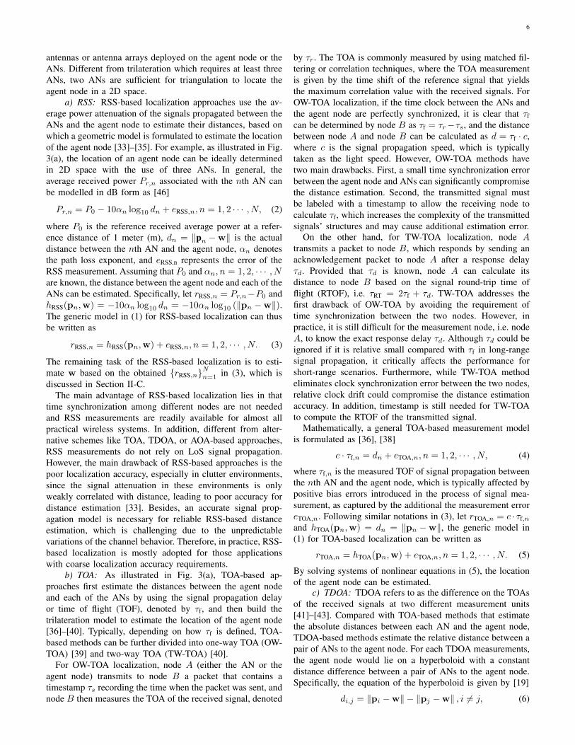
Fig. 4. The procedures of fingerprint-based localization, where pn, n =1, 2, 3 denote the ANs. (a) Offline training phase, where sl is the RFfingerprint at the cell zl. After the test node travels the whole area of interest,the radio map F consisting of all fingerprints in the area will be stored in adatabase. (b) Online localization phase, where the online RSS measurementssw of the agent node is sent to the database. After pattern matching swagainst with the radio map F, the location of the agent node can be estimatedas w.
fingerprint-based methods.In general, the RF fingerprinting-based localization in-
cludes offline training and online localization phases. Asillustrated in Fig. 4, taking the 2D localization as an ex-ample, the area of interest is firstly divided into L cells,where the location of the lth cell is known, denoted byzl = [zx,l, zy,l]
T, l = 1, 2, · · · , L. For offline training, a
mobile test node travels to the L cells and communicateswith the N ANs to measure the RSS fingerprints, whichare denoted as sl = [sl,1, sl,2, · · · , sl,N ]
T for measurementsat zl, l = 1, 2, · · · , L. Then, the entire radio map of thearea of interest is obtained as F = [s1, s2, · · · , sL]T , whichwould be stored in a database for online localization. Foronline localization, a real-time RSS measurements of the agentnode at the location of w = [wx, wy]
T are measured assw = [sw,1, sw,2, · · · , sw,N ]
T , and the location of the agentnode can be estimated as w = [wx, wy]
T based on a rule g(·)that compares the received online measurements sw againstthe radio map F [48], [52],
w = g (F, sw) . (14)
Depending on the mathematical model of RSS fingerprints,there are two main conventional localization approaches: de-terministic and probabilistic.
a) Deterministic: For deterministic approaches, the mea-sured RSSs are assumed to be static. In general, the location ofthe agent node is estimated to be the location of the cell, whose
9
fingerprint is the closest to the online RSS measurements [52],i.e.,
w = arg minl=1,··· ,L
d (sl, sw) , (15)
where d(·) denotes a certain distance metric. For example,applying the Euclidean distance metric in (15), we can obtain
w = arg minl=1,··· ,L
‖sl − sw‖ . (16)
Solving (16) to estimate the location of the agent node isknown as the nearest neighbor (NN) method. Another well-known deterministic method is the K-nearest neighborhood(KNN) [19], [49], where the location estimation is obtainedby averaging the locations of the K cells in the radio map thathave the nearest distances. The weighted KNN (WKNN) is avariant of the KNN method [48], [52], where the selected lo-cations of the closest cells are combined by assigning weightsto estimate the location of the agent node, where the weightsare usually proportional to the inverse of their correspondingd (sl, sw). In general, KNN and WKNN methods can achievebetter performance than NN method. However, as the densityof the radio map increases, NN method may achieve compara-ble performance as KNN or WKNN methods. Technically, RFfingerprinting methods originate from machine learning clas-sification, so other machine learning methods such as supportvector machine (SVM) and linear discriminant analysis (LDA)can be also used for location fingerprinting [19]. Such methodscan achieve better localization accuracy compared with KNN,WKNN, or NN, but with higher computational complexity.The main advantage of the deterministic approaches is theirsimplicity. However, a single static RSS fingerprint of a cellmay not be sufficient to uniquely represent the feature ofthe cell due to the time-varying nature of wireless signalpropagation, so probabilistic approaches are developed.
b) Probabilistic: Probabilistic methods use statistical in-ference between online signal measurement sw and the storedradio map F to estimate the location of the agent node, wherethe RSS fingerprint at a cell is treated as a random vector andthe knowledge of RSS distribution in the area of interests isacquired through offline training. The underlying principle ofprobabilistic localization is the maximum a posteriori (MAP)estimation, which estimates the location of the agent node bymaximizing the conditional probability of the location giventhe online RSS measurements [54], i.e.,
w = arg maxzl,l=1,··· ,L
P (zl|sw) , (17)
where P (zl|sw) is the conditional probability of the agentnode at location zl given the online RSS measurements sw.In the absence of a priori knowledge about the location of theagent node, the probabilities of the agent node at the each cellof the radio map is equal. Then by using the Bayes’ formula,equation (17) can be further transformed into
w = arg maxzl,l=1,··· ,L
P (sw|zl) , (18)
which is known as maximum likelihood (ML) estimation,where P (sw|zl) is the probability of RSS distribution atthe given location zl. Therefore, the probabilistic localizationmethods rely on the estimation of the conditional probability
P (sw|zl). There are two main approaches to approximateP (sw|zl), namely, parametric and non-parametric estimation[19], [52]. For parametric estimation methods, the knownanalytical distribution functions, such as Gaussian, lognormal,and kernel functions, are used to approximate temporal RSScharacteristics. However, these parametric estimation methodsusually require some probabilistic assumptions (like the prob-abilistic independence), which makes it challenging to applyin some practical situations. Unlike parametric estimationmethods, non-parametric density estimation methods do notmake any assumption about the RSS fingerprint distribution.For non-parametric estimation, the fingerprint distributionsare proportional to the current centralized histogram, whichis known as histogram matching [52]. However, for suchmethods, a large number of time samples are needed for eachcell to generate a histogram.
Compared with geometric-based methods, the main advan-tage of fingerprinting methods is their robustness to signalmeasurement errors introduced by multi-path effects. Thisis because that fingerprinting methods transform localizationproblems into the problems of pattern matching by dividing theprocess of localization into offline training and online match-ing phases. In fingerprinting methods, a location is character-ized by its detected signal patterns. Therefore, without havingto know the exact locations of ANs, fingerprinting requiresneither distance nor angle measurement, rendering it especiallyfeasible in clutter environments, like indoor or urban scenarios.However, such methods also have some drawbacks. First,for offline training, it is labor intensive and time-consumingto extract the RF fingerprints and construct the radio map.The selected RF fingerprints must uniquely correspond to agiven location and should have low variability during a certaintime interval. The process of training RF fingerprints is time-consuming since the distribution of RSS fingerprints is usuallynon-Gaussian, skewed, and multimodal. In addition, since thesignal propagation environment is inherently time-varying, theradio map needs to be updated regularly. Furthermore, foronline localization, it is necessary to limit the search size andexploit efficient pattern matching algorithms for reducing thecache consumption and computational complexity. Therefore,compared with geometric-based localization, fingerprinting ismore suitable for small-size environments.
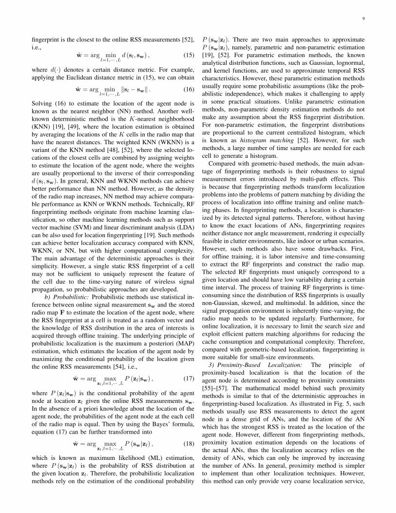
3) Proximity-Based Localization: The principle ofproximity-based localization is that the location of theagent node is determined according to proximity constraints[55]–[57]. The mathematical model behind such proximitymethods is similar to that of the deterministic approaches infingerprinting-based localization. As illustrated in Fig. 5, suchmethods usually use RSS measurements to detect the agentnode in a dense grid of ANs, and the location of the ANwhich has the strongest RSS is treated as the location of theagent node. However, different from fingerprinting methods,proximity location estimation depends on the locations ofthe actual ANs, thus the localization accuracy relies on thedensity of ANs, which can only be improved by increasingthe number of ANs. In general, proximity method is simplerto implement than other localization techniques. However,this method can only provide very coarse localization service,

10
Fig. 5. Proximity-based localization using RSS measurements, where p1,p2 and p3 denote the ANs, w denotes the location of the targeting agentnode, and Pr,n, n = 1, 2, 3 represent the RSS measurements. The locationof the agent node would be determined by comparing the RSSs under certainproximity constraints.
so it is usually used in systems with low requirements onthe location accuracy. The representative application forthis method include Cell-ID (CID) [26], RFID [20] andbluetooth-based localization systems [23], which are oftenused in cellular and IoT networks. Another use case ofproximity-based localization is to reduce the search sizeof fingerprint-based localization before fingerprints patternmatching is performed.
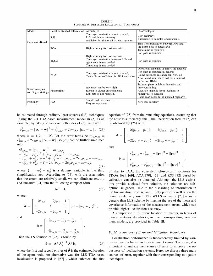
A summary of the aforementioned the above localizationapproaches is provided in Table II, which compares theirdifferences on measurement models, advantages, and disad-vantages.
C. Location Estimators
In general, there are two categories of location estimators,namely, nonlinear and linear, to solve the localization problemsdefined in (1). The nonlinear estimators directly solve theproblems by minimizing a cost function constructed from (1).Such nonlinear estimators usually result in high localizationaccuracy. However, sometimes the global solution of suchschemes may not be guaranteed as their cost functions areusually multi-modal, and nonlinear estimators usually havehigh time complexity if grid or random search is involved.By contrast, linear estimators which convert the nonlinearequations into a set of linear equations can find efficient solu-tions quickly, with degraded localization accuracy comparedto nonlinear estimators.
1) Nonlinear Estimators: Typical nonlinear estimators in-clude the nonlinear least squares (NLS), weighted nonlinearleast squares (WNLS) and maximum likelihood (ML) esti-mators [32]. Base on the generic model (1), the general costfunction of the NLS estimator is defined as [38]
VNLS (w) =
N∑n=1
(rn − h(pn,w))2
= (r− h (w))T(r− h (w)) ,
(19)
where r = [r1, · · · , rN ]T and h(w) =
[h(p1,w), · · · , h(pN ,w)]T are N dimensional vectors.
The solution of NLS estimator corresponds to the estimatedlocation w that minimizes the cost function (19), i.e.,
w = argminw
VNLS(w). (20)
The NLS estimator does not rely on any assumption aboutthe error statistics. However, when the covariance of the errorvector e = [e1, · · · , eN ]
T is available, we can obtain theWNLS estimator, which is defined as [54]
w = argminw
VWNLS(w)
= argminw
(r− h (w))TC−1(e) (r− h (w)) ,
(21)
where C(e) = E[eeT
]denotes the covariance of e, and E [·]
represents the expectation operation. Furthermore, when theerror probability distribution Pe(e) is known, the ML estimatorcan be used for location estimation [58], [59]
w = argminw
VML(w)
= argminw
logPe(r− h(w)).(22)
Note that when the errors satisfy the zero-mean Gaussiandistribution, the ML and WNLS estimators have the sameperformance. In summary, the NLS estimator is simpler thanWNLS or ML estimators and can be a practical choice ifthe noise information is unavailable, while when the errorcovariance matrix is available, WNLS can perform better thanNLS, and the ML is optimal, since it can attain the the Cramer-Rao lower bound (CRLB) [60], [61], which is discussed inSection II-E.
In general, there are two ways to solve the optimizationproblem in (20), (21) and (22). The first one is to perform aglobal exploration by using grid or random search techniques,such as genetic algorithm [62] or particle swarm optimization[63]. However, although such methods can achieve high lo-calization accuracy, they are time-consuming and the globalconvergence may not be always guaranteed. The other way isthe iterative search algorithm, which requires a good initial-ization to avoid trapping at the undesired local minima. Thereare commonly three iterative search schemes, namely, Newton-Raphson [64], Gauss-Newton [65], and steep descent methods[66]. Such methods will start with the initial estimate w0 anditerates until the kth iteration satisfying a certain criterion like∥∥wk − wk−1
∥∥ < ε, where ε is a sufficiently small positiveconstant [66]. In general, the Newton-Raphson and Gauss-Newton methods are more effective than the steepest descentmethod, while the steepest descent method is more stable thanthe former, since the inverse of Hessian matrix may not existin the Netwon-Raphson or Gauss-Newton methods in somecases [32].
2) Linear Estimators: For geometric-based localization,since the function h(·) has a clear expression given by thealgebraic relationships between ANs and the agent node,as discussed in Section II-B, the corresponding localizationproblems may be also solved in closed-form through linearestimators. The linear estimators mainly include the linearleast squares (LLS) and weighted LLS (WLLS). The aim oflinearization is to covert the nonlinear equations in (1) intolinear forms, based on which the location of the agent node can
11
TABLE IISUMMARY OF DIFFERENT LOCALIZATION TECHNIQUES
Model Location-Related Information Advantages Disadvantages
Geometric-Based
RSSTime synchronization is not required;LoS path is not necessary;Available for almost all wireless systems.
Low accuracy;Vulnerable to complex environments.
TOA High accuracy for LoS scenarios.
Time synchronization between ANs andthe agent node is necessary;Timestamp is required;LoS path is assumed.
TDOA
High accuracy for LoS scenarios;Time synchronization between ANs andagent node is not needed;Timestamp is not needed.
LoS path is assumed.
AOA Time synchronization is not required;Two ANs are sufficient for 2D localization.
Directional antennas or arrays are needed;LoS path is assumed in general.(Some advanced methods can work onNLoS condition, which will be discussedin Section III-B).
Scene Analysis(or Fingerprinting) Fingerprints
Accuracy can be very high;Robust to clutter environments;LoS path is not required.
Training phase is labour intensive andtime-consuming;Accurate mapping from locations tofingerprints is needed;Radio map needs to be updated regularly.
Proximity RSS Simple and inexpensive;Easy to implement. Very low accuracy.
be estimated through ordinary least squares (LS) techniques.Taking the 2D TOA-based measurement model in (5) as anexample, by taking squares on both sides of (5), we have
r2TOA,n = ‖pn −w‖2 + e2TOA,n + 2eTOA,n ‖pn −w‖ , (23)
where n = 1, 2, · · · , N . Let the error terms be mTOA,n =e2TOA,n +2eTOA,n ‖pn −w‖, so (23) can be further simplifiedinto
r2TOA,n = ‖pn −w‖2 +mTOA,n
= (wx − px,n)2 + (wy − py,n)2 +mTOA,n= p2x,n + p2y,n + w2
x + w2y − 2wxpx,n − 2wypy,n +mTOA,n
= p2x,n + p2y,n + ξ − 2wxpx,n − 2wypy,n +mTOA,n(24)
where ξ = w2x + w2
y is a dummy variable in the thirdsimplification step. According to [54], with the assumptionthat the errors are relatively small, we can eliminate mTOA,nand linearize (24) into the following compact form
Aθ = b, (25)
where
A =
−2px,1 −2py,1 1...
......
−2px,N −2py,N 1
,θ = [wx, wy, ξ]T,
and
b =
r2TOA,1 − p2x,1 − p2y,1...r2TOA,N − p2x,N − p2y,N
.Then the LS solution of (25) is found by
θ =(ATA
)−1ATb, (26)
where the first and second entries of θ is the estimated locationof the agent node. An alternative way for LLS TOA-basedlocalization is proposed in [67] , which subtracts the first
equation of (25) from the remaining equations. Assuming thatthe noise is sufficiently small, the linearization form of (5) canbe obtained by (25) with
A =
−2(px,2 − px,1) −2(py,2 − py,1) 1...
......
−2(px,N − px,1) −2(py,N − py,1) 1
,and
b =
r2TOA,2 − r2TOA,1 + ‖p1‖2 − ‖p2‖2...r2TOA,N − r2TOA,1 + ‖p1‖2 − ‖pN‖2
.Similar to TOA, the equivalent closed-form solutions forTDOA [68], [69], AOA [70], [71] and RSS [72] based lo-calization can also be obtained. Although the LLS estima-tors provide a closed-form solution, the solutions are sub-optimal in general, due to the discarding of information inthe linearization process, and it only performs well when thenoise is relatively small. The WLLS estimator [73] is moregeneric than LLS scheme by making the use of the mean andcovariance information of the measurement errors, which canprovide higher localization accuracy.
A comparison of different location estimators, in terms oftheir advantages, drawbacks, and their corresponding measure-ment models, are provided in Table III.
D. Main Sources of Error and Mitigation Techniques
Localization performance is fundamentally limited by vari-ous estimation biases and measurement errors. Therefore, it isimportant to analyze their source of error to improve the ro-bustness of localization systems. Here, we discuss three mainsources of error, together with their corresponding mitigationtechniques.

12
TABLE IIICOMPARISON OF DIFFERENT LOCATION ESTIMATORS
Estimators Measurement Model Advantages Disadvantages
NLS
Geometric-based;Fingerprinting;Proximity
High accuracy;Error statistics is not required.
Global optimal solution cannot be guaranteed;High complexity.
WNLS Higher accuracy than NLS.Error covariance is needed;Global optimal solution cannot be guaranteed;High complexity.
ML Highest accuracy compared to other estimators;Can achieve the theoretical CRLB.
Requires error probability distribution information;Global optimal solution cannot be guaranteed;High complexity.
LLS Geometric-based
Closed-form solution is guaranteed;Computationally efficient;Error statistics is not required.
Low accuracy especially for clutter environments.
WLLS Higher accuracy than LLS;Computationally efficient.
Error statistics are needed;May require iterative computation.
1) Multi-path Fading: Multi-path fading commonly existsin wireless channels, which can considerably degrade thelocalization performance. In particular, for narrowband lo-calization systems in clutter environments, the signals thatarrive at the receiver via different paths are superimposedwith each other, resulting them unresolvable at the receiver.Moreover, the multi-path effect varies with signal propagationenvironments, making the signal detection more difficult. Tomitigate this effect, some diversity combining techniques areproposed, and for the ultrawide bandwith (UWB) systems,the multi-path components are usually resolvable temporallywithout resorting to complex algorithms [74], [75]. However,in harsh environments, the large number of mulitpath com-ponents still degrade the localization performance, especiallyfor the geometric-based algorithms which need to distinguishthe LoS path from the large number of NLoS paths to obtainthe location information of the agent node. Recently, a newline of research direction is the multi-path assisted localizationby using the advanced tracking algorithms or by consideringthe signal reflectors as virtual transmitters to achieve highlocalization accuracy [11], [76], [77].
2) NLoS Propagation: The adversary impact of NLoSpropagation lies in that the received NLoS signals weaken thecorrelation between signal measurements and link distance,since it will introduce a positive bias to the range estimate.In general, there are three methods to cope with the NLoScondition. The first method is based on the statistical infor-mation of the NLoS error. By assuming a scattering modelof the environment, the statistics of signal measurementscan be obtained, and then the well-known techniques, likeMAP or ML, can be used to mitigate the effects of NLoSerrors. However, the difficulty of such methods is to obtainan accurate model, which may change with terrain and/or theconstruction/demolition of buildings. The second method usesall NLoS and LoS measurements with appropriate weights tominimize the effects of the NLoS contributions, where theweights are generated from the localization geometry and theANs layout. Although this method is effective even in thecases without LoS measurements, its solution is unreliablebecause the NLoS errors are always present. The third methodis to identify and discard those NLoS measurements, andperform localization only based on the LoS measurements.In essence, the problem of NLoS identification in this method
is converted into a statistical detection problem, where theNLoS and LoS conditions are considered as two hypotheses,and the goal of the problem is to figure out a metric todifferentiate the NLoS and LoS hypotheses. For instance, wecan identify the NLoS path based on the statistics of rangemeasurements. Usually, the NLoS range measurements whichare positively biased with non-Gaussian distribution tend tohave a larger variance compared to the LoS counterpart withGaussian distribution. However, in some harsh environments,almost all measurements come from NLoS paths, so there areinsufficient LoS measurements for localization. For such cases,the localization methods using NLoS measurements and geo-metrical information are proposed [32]. In general, these NLoSlocalization techniques can be divided into two categories. Oneis NLoS localization using signal measurements combiningwith the priori knowledge of the environment map. The otheris the localization using the measurements from scatters. Notethat in the latter method, the NLoS measurements are firstidentified, and then the geometrical relationship among theANs, the agent node and the scatters are used to locate theagent node.
3) Systematic Error: The systematic errors refer to theerrors originated from the localization system itself, such asthe imperfect signal measurements and radio miscalibration.For instance, in time-based localization systems, the ANs areequipped with the oscillators for time synchronization. How-ever, the oscillators often experience independent frequencydrifts, resulting in clock drift and offset, that may degrade thelocalization accuracy. Systematic errors often bias the locationestimators, making the mean of the estimator larger than thetrue value. These errors are usually constant with respect tothe targeting location and cannot be eliminated by averagingover a multiple repeated measurements. Nevertheless, sometechniques can effectively mitigate these errors. For example,real-time infrastructure calibration can mitigate the localiza-tion performance degradation, where wireless links amongANs are made periodically to calibrate the parameters of thelocalization system. Alternatively, some techniques like clockoffset correction and recursive Bayesian approach have beenproposed to tackle systematic errors [78], [79].

13
E. Performance Metrics
The performance of localization systems can be evaluatedfrom various aspects. In this subsection, we outline the mainperformance evaluation metrics, including accuracy, precision,complexity, coverage and scalability, while a performancecomparison across several localization infrastructures is givenin Section II-F.
1) Accuracy: Accuracy (or location error) is usually mea-sured as the Euclidean distance between the estimated locationw and the actual location w of the agent node, which istypically the most important performance metric to analyzethe overall system performance. In practice, various statisticscan be adopted for this evaluation criterion, such as the meansquare error (MSE) of the location estimates, which is definedas
eMSE(w) = E[‖w −w‖2
]= tr (C (w,w)) + ‖E (w)−w‖2 ,
(27)
where tr(·) indicates the matrix trace, and C (w,w) denotesthe covariance matrix of w and w, which is defined as
C (w,w) = E[(w −w)(w −w)T
]. (28)
The first and second terms of (27) represent the variance andbias of the estimated location, respectively. Note that the biasis usually a constant unknown error introduced by the signalmeasurement, which can be mitigated through appropriatemethods. For unbiased cases, the CRLB gives the lower boundon the variance of w [60], [61], i.e.,
C (w,w) � I−1 (w) , (29)
where � denotes the matrix C (w,w) − I−1 (w) is positivesemidefinite, and I(w) is the Fisher information matrix (FIM)of w, given by [38]
I (w) = −E[∂2 lnP (r | w)
∂w∂wT
], (30)
where P (r | w) denotes the conditional probability densityfunction (PDF) of the measurement vector r. Taking the2D TOA-based localization as an example, the measurementvector can be generated by (5), which is a vector of themeasured distances between the agent node and each of ANs,denoted by
r = d =[d1, d2, · · · , dN
]T. (31)
For convenience, here we consider the measurement errorseTOA,n, n = 1, · · · , N that are zero-mean Gausssian dis-tributed, and the conditional PDF of measured distance d is
P(d | w
)=
N∏n=1
1√2πσ2
n
exp
−(dn − dn
)22σ2
n
, (32)
where dn, n = 1, · · · , N denote the actual distances betweeneach AN and the agent node. By substituting (32) into (30),the FIM can be calculated as [59]
I (w) =
N∑i=1
(wx−px,i)2σ2i d
2i
N∑i=1
(wx−px,i)(wy−py,i)σ2i d
2i
N∑i=1
(wx−px,i)(wy−py,i)σ2i d
2i
N∑i=1
(wy−py,i)2σ2i d
2i
.(33)
Then substituting (33) into (29), the CRLB for the TOA-basedlocalization method can be obtained. In a similar manner,the FIMs for TDOA, RSS, and AOA measurements can alsobe obtained. The CRLB implies that the MSE of locationestimates satisfies the following bound
eMSE(w) = E[‖w −w‖2
]≥ tr (C (w,w)) ≥ tr
(I−1 (w)
).
(34)
Another useful evaluation criterion is the root mean squareerror (RMSE), which is the root of the MSE with the followingbound [24]
eRMSE(w) =
√E[‖w −w‖2
]≥√
tr (Cov (w)) ≥√
tr (I−1 (w)).
(35)
The CRLB determines the attainable location accuracy ofthe unbiased system. However, many practical estimators arebiased because of signal NLoS propagation and other factors,so in practice the system performance may not achieve theCRLB. Other bounds like the Bayesian Cramer Rao bound[80], Weiss-Weinstein bound [81], and extended Zik-Zakaibound [82] are tighter but require more complicated evalu-ations compared with CRLB.
2) Precision: Precision reveals the variation of locationestimation with respect to the localization accuracy [19].Specifically, precision measures the statistical characterizationof the accuracy which varies over many localization trials. Insome works, the geometrical dilution of precision (GDOP) isalso used to measure the variation of localization errors [19].Taking the TOA-based localization as an example, the GDOPis defined as [38]
GDOP =eRMSE(w)
eRMSE(d), (36)
where the numerator and denominator are the RMSE ofthe location estimate and the range estimate, respectively.The smaller GDOP value means the better performance onlocalization precision. In addition, the GDOP also reveals therelation between the achievable localization accuracy and thegeometry distribution of the ANs, which can be adopted asa criterion for ANs placement and selection to minimize theGDOP value.
Another evaluation metric is the localization error outage(LEO), which is defined as the probability when the localiza-tion error exceeds a certain threshold eth [22]
LEO(eth) = Pr {‖w −w‖ ≥ eth} . (37)

14
An equivalent expression of (37) is the cumulative distributionfunction (CDF) of the localization error defined by
CDF(eth) = 1− LEO(eth), (38)
which denotes the success probability of location estimationswith respect to a predefined accuracy. In practice, the LEO orCDF reveals the probability of confidence in the location esti-mate. When the accuracies of two localization algorithms arethe same, the algorithm that gives lower LEO or higher CDFvalues has better precision [22]. For example, a localizationsystem with CDF(1.5) = 0.9 (a precision of 90% within 1.5m) performs better than that with CDF(1.5) = 0.5 (a precisionof 50% within 1.5 m).
3) Complexity: The complexity of a localization systemdepends on the hardware, process of signal measurement, andcomputational complexity of the localization algorithm [19].In general, it is difficult to analytically derive the complexityformula of different localization techniques. Therefore, thecomputational complexity of the location estimators is usuallytreated as the complexity of the localization system. Thereis always a trade-off between accuracy and complexity inthe sense that more accurate localization usually requiresthe higher computational complexity. On the other hand, thelocation update rate or latency can be also used as a criterion toevaluate the system complexity, which reflects the time delaybetween two consecutive location updates for the same agentnode and is very important for navigation.
4) Coverage and Scalability: In general, the localizationperformance degrades as the distance between each AN andthe agent node increases. The coverage refers to the maxi-mum area where the localization system can provide effectivelocalization services with guaranteed performance in terms ofaccuracy, precision, latency, and so on. In general, the coveragecan be roughly classified into global, local, and indoor cover-age depending on different localization infrastructures. One theother hand, the scalability reflects the adaptive capability of thelocalization system when the localization scope gets large [19].As the localization coverage increases, the wireless channelsmay become congested and the localization system need toperform more signal measurement and calculation operations.
F. Localization Infrastructures
There are two basic ways to deploy the localization systems.The first one is to build a dedicated localization infrastructure,like the GNSS. The second way is to reuse the existingwireless network infrastructures with the signals of opportu-nity (SoOP), like cellular networks, WLAN, etc., to providewireless localization services, in addition to communicationservices. For the first approach, the main advantage is thatit can achieve high localization performance by using spe-cific reference signal and professional hardware, while thedrawback is the cost of the hardware and the limitation onthe system scalability. For the second approach, it avoids theexpensive and time-consuming deployment of infrastructure,but such systems usually rely on sophisticated algorithmsto improve the performance. In this subsection, we mainlydiscuss the most popular localization infrastructures, including
GNSS, cellular networks, WiFi, and UWB based localizationsystems, and a detailed comparison on their performance isgiven in Table IV.
1) GNSS: Several countries in the world have alreadydeveloped and launched various GNNSs, including the GPSby U.S., the Galileo by Europe, the Beidou by China, theGLONASS by Russia, as well as other regional systemslike the Japanese Quasi-Zenith satellite system (QZSS) andthe Indian regional navigational satellite system (IRNNS).Although all of these GNNSs introduce different innovation atthe system and signal levels, they share common theoreticaland functional principles. Taking the most popular GPS as anexample, it is a self-localization system based on a man-madeconstellation of 27 earth-orbiting satellites. The localizationtechniques behind GPS are the OW-TOA or TDOA methods,where at least four clearly visible satellites are required for theagent node to localize itself in terms of latitude, longitude, andaltitude. In general, the localization accuracy of GPS rangesfrom 10 m to 20 m [83], and the precision performance ishighly dependent on the geometric distribution and selectionof satellites, which can be measured by the GDOP value.The stand-alone GPS suffers from the problem of time tofirst fix (TTFF) or cold start; that is, when a GPS receiveris first turned on, it needs a long time (about 30 s or evena few minutes) to acquire the satellite signals. To this end,an assisted-GPS (A-GPS) technique has been developed [83],[84], which uses a location server equipped with the GPSreceiver that can simultaneously detect the satellites to helpthe user equipment (UE) to acquire GPS signals more quickly.Although GPS can provide localization service globally, itsperformance is degraded in severe scattering environments,like indoor or urban areas.
2) Cellular Networks: Initially, cellular networks was de-signed for communications, and all UEs in the networks thatneed location services resorted to the GNSS. However, dueto the poor performance of the GNSS in urban and indoorenvironments, the cellular-based localization was proposed asa good complementary of GNSS to enhance its performanceand robustness. The first cellular-based localization systemis the E-911 [85] introduced by the Federal CommunicationCommission (FCC) of the U.S. to provide emergency ser-vices. Moreover, since the location information within thecellular networks can be exploited for commercial servicesand network optimization, in the subsequent cellular networksstandards from 2G to 4G, more advanced cellular-based local-ization techniques were proposed. For cellular networks, bothof the uplink and downlink between the BSs and UEs can beexploited for localization. In 2G cellular standard, the local-ization schemes in global system for mobile communications(GSM) and code-division multiple access (CDMA) networkinclude CID, timing advance (TA), and enhanced observedtime difference (E-OTD) [27], [86]–[88], which are mainlybased on the uplink time-based measurements that requiredstrict time synchronization, leading to coarse localization accu-racy, ranging from 50 m to 550 m. In 3G networks, the specificlocation measurement units (LMUs) were introduced in wide-band CDMA (WCDMA) systems, which can be integratedwith the BSs to improve the signal measurement performance.

15
TABLE IVCOMPARISON OF DIFFERENT LOCALIZATION INFRASTRUCTURES
Example Techniques Type Performance
GNSS GPS OW-TOA/TDOA Trilateration10-20 m accuracy;Global coverage;About 30 s latency.
Cellular Networks
2G CID + TA ProximityAbout 550 m accuracy;Local area coverage;Low latency.
E-OTD Trilateration50-300 m accuracy;Local area coverage;Medium latency.
3G OTDOA/UTDOA Trilateration50-200 m accuracy;Local area coverage;Medium latency.
RFPM Scene analysis Over 50 m accuracy;Local area coverage.
A-GPS Trilateration10-50 m accuracy;Global coverage;High latency.
4GE-CID Angulation + Proximity
About 150 m accuracy;Local area coverage;Low latency.
OTDOA/UTDOA Trilateration25-200 m accuracy;Local area coverage;Medium latency.
A-GNSS TrilaterationLess than 10 m accuracy;Global coverage;High latency.
WiFi IEEE 802.11 RFPM Scene analysis1-5 m accuracy;50-100 m coverage in general;Medium latency.
UWB IEEE 802.15.4a TOA/TDOA Trilateration0.1-1 m accuracy;Indoor area coverage;Medium latency.
The uplink localization methods in 3G networks are similar tothose in 2G networks, where the enhanced CID (E-CID) anduplink TDOA (UTDOA) are the improved versions of CIDand E-OTD, respectively [26]. Different from 2G localization,the localization method based on the downlink signals wasspecified in 3G networks, i.e. observed TDOA (OTDOA).The OTDOA information is measured as the reference signaltime difference (RSTD) by the UE, which then reports theRSTD to cellular networks to calculate its location. Moreover,a RF pattern matching (RFPM) method was proposed in the3GPP Release 10 [89]. In addition, the A-GPS method isadopted by 3G networks, which can provide location servicein GPS-denied areas. In general, the localization accuracy of3G networks ranges from 50 m to 200 m [90]–[92]. Thelocation services in 4G long term evolution (LTE) was firstlydefined in Release 9 [93]. Different from 2G or 3G networks,the 4G networks specify the LTE positioning protocol (LPP)[94] to exchange information between UE and the remotelocation server. Furthermore, a dedicated positioning referencesignal (PRS) was introduced in LTE standards, which hashigh configurability in terms of power, time, and frequencyallocation, and can improve localization performance [95].In the forthcoming 5G networks, the location information isbecoming more critical for various application [17], includingcontent prefetching, radio environment mapping, proactiveradio resource management, etc.. All of the prospective appli-cations require the localization services with higher accuracy.Moreover, the availability, scalability, security, as well as
privacy are also new challenges for localization systems [20].Fortunately, the 5G communication systems enabled by highercarrier frequencies, wider signal bandwidths, denser networks,and Massive MIMO technologies can bring new opportunitiesfor localization, which will be discussed in the Section III.
3) WiFi: WiFi technology can be used as a promisingindoor localization scheme, thanks to its ubiquitous availabilityand handy for short-range RSS measurements. It usually oper-ates in two unlicensed bands, i.e. 2.4 GHz (IEEE 802.11b/g)and 5 GHz (IEEE 802.11a), with a range of 50-100 m ingeneral [51], and has now increased to about 1 kilometer(km) in IEEE 802.11ah [96]. The main advantage of WiFi-based localization is its almost ubiquitous availability sincemost smart devices today are WiFi enabled. However, WiFisignals transmit on the unlicensed industrial, scientific andmedical (ISM) band which are vulnerable to interference [51].The most commonly known WiFi-based localization approachis the RSS-based fingerprinting, while TOA-, TDOA- andAOA-based methods are relative less used since angular andtime delay measurements are complex. Usually, the accuracyof typical WiFi localization systems is approximately 1 to 5m with a few seconds update rate [97]–[99]. Recently, theaccuracy of WiFi-based localization systems has achieved thedecimeter-level in the certain scenarios [100], [101]. Thereare many survey papers providing reviews about WiFi-basedlocalization, e.g., [50], [51], and [99]. In [51], the authorsprovided a comprehensive overview about WiFi-based indoorlocalization techniques, while in [50] the authors focused on
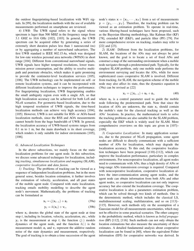
16
the outdoor fingerprinting-based localization with WiFi sig-nals. In [99], the localization methods with the use of availablemeasurements performed on smartphone are reviewed.
4) UWB: The UWB signal refers to the signal whosespectrum is lager than 500 MHZ in the frequency range from3.1 GHZ to 10.6 GHz [102], [103]. In general, the UWBspectrum can be acquired either by generating a series ofextremely short duration pulses less than 1 nanosecond (ns)or by aggregating a number of narrowband subcarriers. Thefirst UWB standard is IEEE 802.15.4a, which was designedfor low-rate wireless personal area networks (WPAN) in shortrange [104]. Different from conventional narrowband signals,UWB signals have higher temporal resolutions, lower trans-mission power consumption, and the ability to resolve multi-path and penetrate obstacles, which makes it quite promisingto provide the centimeter-level localization services [105],[106]. The UWB technology can be implemented on self- orremote localization systems, and it can be incorporated withdifferent localization techniques to improve the performance.For fingerprinting localization, UWB fingerprinting enablesthe small ambiguity region even with a single AN, so thathigh localization accuracy can be achieved for both LoS andNLoS scenarios. For geometric-based localization, due to thehigh temporal resolution of UWB signals, the time-basedlocalization methods can achieve very high accuracy [104],[105]. However, UWB is not suitable for RSS- or AOA-basedlocalization methods, since the RSS and AOA measurementscannot benefit from the huge bandwidth of UWB. In general,the localization accuracy of UWB-based systems ranges from0.1 m to 1 m, but the main drawback is its short coverage,which renders it only suitable for indoor environments [105],[106].
G. Advanced Localization Techniques
In the above subsections, we mainly focus on the staticlocalization problems for one agent node. In this subsection,we discuss some advanced techniques for localization, includ-ing tracking, simultaneous localization and mapping (SLAM),cooperative localization and data fusion.
1) Tracking: The problems of tracking can be viewed as asequence of independent localization problems, but in the moregeneral sense, besides location estimation, it further involvesthe estimation of velocity, acceleration, and all past statesof the mobile agent node. Compared with static localization,tracking entails mobility modelling to describe the agentnode’s movement. Mathematically, the problems of trackingcan be formulated as
xt = ζ(xt−1) + zt (39a)
yt = h(xt) + vt, (39b)
where xt denotes the global state of the agent node at timestep t, including its location, velocity, acceleration, etc., whileyt is the measurement at step t; the function ζ(·) modelsdynamics of the agent node, and the function h(·) is themeasurement model; zt and vt represent the additive randomnoise of the state dynamics and measurement, respectively.The goal of tracking is to obtain a time succession of the agent
node’s states x = {x1, · · · ,xT } from a set of measurementsy = {y1, · · · ,yT }. Therefore, the tracking problem can beviewed as an estimation problem. To operate in real-time,various filtering-based techniques have been proposed, suchas the Bayesian filtering methodology, like Kalman filer (KF)[78], extended KF (EKF), and particle filter (PF) [79]. Formore comprehensive review on tracking, readers may refer to[22] and [23].
2) SLAM: Different from the localization problems, forSLAM, the locations of the ANs may not always be priorknown, and the goal is to locate a set of fixed ANs andconstruct a map of the surrounding environment when a mobilenode navigates through a predetermined path. Typically, for thesimplest SLAM problem, only one mobile node performs theenvironment surveying and locates the ANs, while for moresophisticated cases cooperative SLAM is involved. Differentfrom tracking, for SLAM, the navigation scheme of the mobilenode may also affect its state, thus the dynamics equation in(39a) can be revised as [22]
xt = ζ(xt−1) + ut + zt, (40)
where ut is a control parameter used to guide the mobilenode following the predetermined path. Note that since thelocation of ANs are unknown, the state xt should containthe mobile’s state for the classical tracking as well as theANs’ locations. In practice, the mathematical tools to solvethe tracking problems are also suitable for the SLAM problem,especially the EKF which is widely used for SLAM. Morecomprehensive overviews on this topic are given in [107]–[109].
3) Cooperative Localization: In many application scenar-ios, due to the presence of NLoS propagation, some agentnodes are difficult to directly communicate with a sufficientnumber of ANs for localization, which may degrade thelocalization accuracy. To this end, the cooperative localiza-tion techniques have been proposed [110]–[112], which canimprove the localization performance, particulary in complexenvironments. For noncooperative localization, all agent nodesneed to communicate with ANs, thus a high density of ANs orlong-range ANs transmission coverage is required. Comparedwith noncooperative localization, cooperative localization al-lows the inter-communication among agent nodes, and theagent node can obtain information from both ANs and otheragent nodes, so cooperative localization can not only improveaccuracy but also extend the localization coverage. The coop-erative localization is also a parameters estimation problem,which can be solved through two kinds of methods. One isthe deterministic method, which includes the classical LS,multidimensional scaling, multilateration, and so on [113]–[115]. However, such methods rely on the assumption of aGaussian model for all measurements uncertainties, which maynot be effective in some practical scenarios. The other categoryis the probabilistic method, which is known as belief propaga-tion (BP) [112], [116]. Such methods can not only obtain thelocation estimations but also measure the uncertainty of theseestimates. A detailed fundamental analysis about cooperativelocalization can be found in [60], where the equivalent Fisherinformation (EFI) for cooperative networks was derived. In

17
[112], the authors discussed the main cooperative localizationapproaches from the perspective of estimation theory andfactor graphs.
4) Data Fusion: Due to the multi-path effects, the perfor-mance of localization systems that only use a single type ofmeasurements is severely limited in complex environments.To this end, the study on fusing different types of infor-mation to improve the localization performance has gaineda momentum [78], [79], [117], [118]. So far, the wirelessnetwork has become heterogeneous with various wirelesstechnologies, such as cellular network, WLAN, RFID, andBluetooth. Therefore, hybrid data fusion (HDF) has attractedresearch interest for unlocking the full potential of localizationsystems [23]. An example of data fusion localization is theSiRstarV [23], which combines real-time data from GNSSsatellites, WLAN, cellular, as well as multiple IMU sensors toimprove the localization performance. Numerical results showthat its positioning error is within 9 m for 68% cases and 13.1m for 95% cases over several tests [119]. A generic frameworkof fusion technologies used for tracking is provided in [117],where fusion exists across all stages of localization systems. Inthe signal measurement stage, different signal measurementslike TOA, TDOA, AOA, and RSS are combined. In the posi-tion estimation stage, different localization techniques such astrilateration, triangulation, and fingerprinting are performed.Finally, a temporal filter like EKF is applied to smooth theestimated user trajectory with the help of information gatheredfrom multiple IMU sensors.
III. INTEGRATED LOCALIZATION AND COMMUNICATIONFOR 5G AND BEYOND
The future mobile communication networks are expected torealize the vision of Internet of everything (IoE) with a versa-tile networks not only for ubiquitous communications, but alsofor seamless localization and intelligent automatic control withhigh accuracy [3], [120]. To fulfill this magnificent goal, it isnecessary to develop high performance localization techniques,so as to not only meet the requirements of various emergingcommercial and industrial on location-based services, but alsoto improve the communication performance in various aspectsat different network layers. In this section, we first overviewthe recent standardizations of 3GPP on localization technolo-gies in 5G NR from Release 15 to Release 17, and discuss thedeveloping trends of the localization systems. Then we discussthe enabling technologies of 5G networks towards centimeter-level localization. Since the accurate location informationis beneficial for communications, we overview the location-aware communication techniques in different network layers.After that, due to the correlation between communicationand localization, we discuss the co-design of localization andcommunication systems and attempt to give some insightsfor future network design. Finally, as a promising visionof 6G, we discuss the development trends of localizationand communication techniques in future aerial-and-groundintegrated networks.
A. 3GPP Standardizations for 5G Localization
Compared with 4G-LTE, 5G networks enabled by highercarrier frequencies, wider bandwidth, and massive antenna ar-rays is expected to achieve enhanced localization performancein terms of accuracy, reliability, coverage and latency [121].In general, the localization accuracy of LTE is between 25m and 200 m, while as reported by 3GPP, the localizationsystems in 5G networks need to achieve submeter-level oreven centimeter-level accuracy with low latency. In Release15, a general description of location services (LCS) and thecorresponding requirements are given in TS 22.071 [1]. Re-lease 15 specifies the CID and radio access technology (RAT)-independent positioning methods by reusing LPP [94], but theRAT-dependent positioning methods are excluded. In Release16, the recent new use cases of localization are identified in TR22.872 [122], which mainly includes wearables, advertisementpush, flow monitoring and control, as well as emergency call.The accuracy requirements for such applications range from 1m to 3 m in indoor scenarios, and below 50 m horizontaland 3 m vertical in outdoor scenarios, with less than 10seconds (s) TTFF and 1 s latency. Such requirements cannotbe satisfied with the current cellular networks, e.g. LTE, so astudy item was concluded in March 2019 to investigate the NRpositioning support, and the technical report is summarized inTR 38.855 of Release 16 [123]. In Release 16, the regulatoryrequirements on positioning are listed as follows:• Horizontal positioning error less than 50 m for 80% of
UEs.• Vertical positioning error less than 5 m for 80% of UEs.• E2E latency and TTFF less than 30 s.
These are regraded as the minimum performance targets forNR positioning studies. Furthermore, for commercial use casesin indoor and outdoor scenarios, the localization technologiesshould meet the following requirements:• For indoor deployment scenarios, the horizontal and
vertical positioning error less than 3 m for 80% of UEs.• For outdoor deployment scenarios, the horizontal posi-
tioning error is less than 10 m, and vertical positioningerror is less than 3 m for 80% of UEs.
• E2E latency is less than 1 s for both indoor and outdoordeployment scenarios.
In order to fulfill the above requirements, Release 16 rec-ommends the following RAT-dependent localization methods,including downlink TDOA (DL-TDOA), downlink AOD (DL-AOD), uplink TDOA (UL-TDOA), uplink AOA (UL-AOA),multi-cell RTT (Multi-RTT), and E-CID. In addition, thecombination of RAT-dependent and RAT-independent tech-niques like GNSS, Bluetooth, WLAN, and sensors are alsoconsidered for NR positioning. The simulation results ofthese proposed NR positioning methods are presented in[123], which considers three different scenarios, i.e. urbanmacro (UMa), urban micro (UMi), and indoor office (InH).The simulation results show that DL-TDOA can meet theregulatory requirements in all scenarios, while under somespecific evaluation assumptions, some other techniques canmeet the requirements of commercial performance [121]. Tosatisfy the increasing requirements on localization accuracy

18
resulting from new applications and industrial IoT (IIoT) usecases, the studies on NR positioning enhancements is ongoingin Release 17 (TS 38.857). As the recommendation of TS38.857, the NR positioning in Release 17 should meet thefollowing exemplary performance targets:• For general commercial use cases (e.g. TS 22.261 [94]),
the submeter-level positioning accuracy should be guar-anteed.
• For IIoT use cases (e.g. TR 22.804 [124]), positioningerror should be less than 0.2 m.
• The latency requirement is less than 100 ms generally,while for some IIoT use cases, the 10 ms latency isdesired.
Two main goals of TS 38.857 are: i) study enhancementsto support high accuracy, low latency, network efficiency (orscalability), and device efficiency; ii) study solutions to supportintegrity and reliability of assistance data and position infor-mation. Furthermore, the enhancements on the combinationof diverse positioning techniques and the flexibility of thenetworks are further emphasized. To meet the requirements ofthe emerging autonomous applications, the future localizationtechnology should not only guarantee the high accuracy, butalso be able to determine the reliability and uncertainty orconfidence level of the location-related data.
B. Towards Centimeter Localization for 5G and Beyond
Massive MIMO, mmWave, UDNs and device-to-device(D2D) communication are four underlying technologies of 5Gnetworks, which can not only improve the communicationperformance, but also potentially benefit for localization [17].For massive MIMO, the BS equipped with a large antennaarray can steer highly directional beams and provide highangular resolution, which can be utilized for angle-basedlocalization [125]. The mmWave technology can provide largebandwidth on the order of GHz, which offers high temporalresolution, thereby ensuring more accurate time-based local-ization [126]. In addition, since mmWave signals suffer fromhigh path loss than the sub-6 GHz counterparts, the cell sizein 5G networks will shrink, which renders UDN a promisingtechnology for 5G networks. The high density of BSs in UDNwill increase the LoS probability, which may also improve thelocalization performance. On the other hand, the promisingD2D communication, where two neighboring devices directlycommunicate with each other while bypassing the BS, mayflourish the device-centric cooperative localization.
1) mmWave Massive MIMO Localization: The main advan-tage of massive MIMO is its unprecedented potential of highspectral efficiency [127]–[129]. In massive MIMO systems, theBS equipped with a large number of antennas can serve a largenumber of UEs simultaneously with high data rates in the samefrequency through dense spatial multiplexing. This is achievedvia beamforming/prcoding by large antenna arrays with highangular resolution, where the channels among different UEsare asymptotically orthogonal [127], [130]. In general, thelarge antenna array can be deployed as one-dimensional lineararray or two-dimensional planar array, e.g. uniform lineararrays (ULAs) [131] versus uniform rectangular arrays (URAs)
[132]. For ULA with N antenna elements, the beam can steerin 1D angles θ, and the unit-norm array response vector is[131]
a(θ) =1√N
[1, ej
2πλ d sin(θ), · · · , ej(N−1) 2π
λ d sin(θ)]T, (41)
where λ is the signal wavelength and d is the distance betweenthe adjacent antenna elements. For URA with N = Nx ×Nyantenna elements, the operation of beamforming lies in 2Dangles referred to azimuth and elevation angles (θ, φ), and theunit-norm array response vector is [132]
[a(θ, φ)]nx,ny = 1√Nej
2πλ d sin(φ)[(nx−1) cos(θ)+(ny−1) sin(θ)],
nx ∈ {1, · · · , Nx} , ny ∈ {1, · · · , Ny} .(42)
Another promising technology of 5G networks is mmWavecommunication, which can achieve high data rate with lowlatency, due to its availability of the large bandwidth on theorder of GHz [133]. In particular, mmWave communicationoperates at a carrier frequency range from around 30 GHzto 300 GHz. The mmWave communication at 60 GHz withbandwidth up to 7 GHz has been standardized for WPANs,e.g., IEEE 802.11ad [134] and IEEE 802.15.3c [135]. In[126], the authors compared the raw resolution of time-basedlocalization across different frequency bands, where the rawresolution is defined as the ratio of the the speed of lightand the available bandwidth. They revealed that mmWavesignal specified in IEEE 802.11ad with bandwidth over 2GHz can achieve raw resolution of roughly 15 cm, whilethat of the UWB signal with bandwidth over 500 MHzis only about 60 cm. Compared with conventional locationreference signals, which are usually transmitted on the ISMfrequency bands, and suffer from severe interference andmulti-path effects, mmWave signals can reduce the probabilityof interference and have the capability to resolve the multi-path components thanks to the very large bandwidth [136].Another important feature of mmWave transmission is thechannel sparsity; that is, only a limited number of propagationpaths can reach the receiver due to the short signal wave-length, which can be also exploited to enhance the localizationperformance [137], [138]. However, to overcome the highpath loss associated with mmWave signals due to the shortwavelength [139], mmWave transmission is usually combinedwith massive MIMO for directional beamforming, for whichthe accurate angular information can be extracted and utilizedfor localization. Therefore, mmWave massive MIMO-basedlocalization may significantly outperform the conventionalangle-based localization at lower frequencies, which sufferfrom rich scattering and poor multi-path separability [131].As illustrated in Fig. 6, compared with traditional sub-6 GHzsystem, the limited scattering and high directivity are uniquecharacteristic of mmWave massive MIMO communications,which bring new opportunities for localization. In the fol-lowing contents, we discuss the mmWave massive MIMOlocalization in terms of channel model, parameter estimation,and localization approaches.
a) Channel Model: For convenience, we consider aMIMO system equipped with ULAs with Nt antennas at the

19
(a) Sub-6 GHz system with omnidirectional antennas
(b) mmWave system with directional antennas
Fig. 6. Signal propagation in sub-6 GHz and mmWave systems. (a) Forsub-6 GHz system with omnidirectional antennas, signals suffer from richscattering and poor multi-path separation capability. (b) For mmWave systemwith directional antennas, signals will arrive at the receiver with very fewpaths due to the high carrier frequency and high antenna direction.
BS and Nr antennas at the UE. The corresponding MIMOchannel can be modelled as [140]
H(t) =
L∑l=1
αla(θr, l)a(θt, l)Hδ(t− τl), (43)
where L denotes the total number of multi-paths, which isusually small due to the multi-path sparsity in mmWave regime[140]; αl and τl represent the complex path gain and the delayof the lth path, respectively; a(θr,l) and a(θt,l) are the antennaarray response vectors for angles θr,l and θt,l seen by theUE and BS, respectively. The sparsity of mmWave channelcan simplify the estimation of channel parameters [137]. Thismethod uses a virtual representation for (43) by samplingin time, frequency, and/or space with the aid of the discretefourier transform (DFT). For instance, the beamspace MIMOchannel can be represented as
Hb(t) = UHr H(t)Ut, (44)
where Hb(t) is the beamspace channel matrix, which is alinear equivalent representation of the antenna domain channelmatrix H(t), Ur and Ut are the DFT matrices whose columnsare response and steering vectors, respectively, which areorthogonal. Estimating parameters from Hb(t) is much easierthan the parameter estimation based on H(t), since the latterdetermines the parameters in a nonlinear manner.
b) Parameter Estimation: For MIMO systems, the sourcelocalization involves the AOAs and AODs estimation, whichcan be classified into localization for point sources and dis-tributed sources [141], [142]. For point source localization,the signal of each source emitted from a single AOA or theAOAs of different sources are distinguishable. On the otherhand, for the distributed sources localization, the signal ofeach source is emitted from an angular region. In general,point sources usually correspond to the LoS propagationscenarios [141], while distributed sources are commonly usedfor the multi-path scenarios [142]. For distributed sources,they can be further classified into coherently distributed (CD)sources [143] and incoherently distributed (ID) sources [144],depending on whether they are slowly time-varying channelsor rapidly time-varying channels.
In general, the parameters for estimation include the azimuthand elevation angles of signal departure and arrival, signalpropagation delay, Doppler shift, and the corresponding uncer-tainty of these parameters. The channel parameter estimationapproaches can be categorized based on the source type. Forpoint sources, the authors in [145] categorized the channelparameter estimation methods into subspace-based and com-pressive sensing methods. The subspace-based methods treatthe parameters into tensors, and use the tensor decompo-sition method to reduce the dimensionality. Such methodscan achieve a good balance between estimation accuracy andcomputational complexity [146]. Compressive sensing is apromising method to recover the sparse signals, which is par-ticularly suitable for mmWave massive MIMO system due toits sparsity in angular and delay domain [147]. For distributedsources, the parameter estimation can be classified into CDsources and ID sources estimation. The classical estimationapproaches for point sources have been successfully appliedinto CD sources estimation [148]–[150], and the multiplesignal classification (MUSIC) algorithms were employed toestimate the AOA of CD sources [143]. However, the pa-rameter estimation for ID sources is more complicated. Thesemethods can be generally divided into parametric methods andnon-parametric methods. The parametric approaches includeML [151], covariance matching [152] and pseudo-subspace[153]. The ML estimation is optimal [151], but it suffers fromhigh complexity. The LS estimator are proposed by using thecovariance matrix matching techniques to reduce the compu-tational complexity [152]. The non-parametric approaches likebeamforming approaches [154] have lower the computationalcomplexity but with compromised performance compared withparametric approaches.
c) Localization Approaches: The conventional localiza-tion approaches can be also used in mmWave MIMO systemsfor improving localization performance. In [155] and [156], a3D localization method was proposed by using hybrid signalmeasurements in mmWave systems, which can joint estimatethe position and velocity of the UEs and construct the envi-ronment maps. In [157], the method based on RSS measure-ments of mmWave signals was proposed, which can achievelocalization accuracy of one meter. The mmWave-based objecttracking was proposed in [158], where the RSS and signalphase were used as the features for tracking an object. In [126],

20
a set of feasible localization approaches in mmWave bandswere discussed, and the results demonstrated that mmWavelocalization can achieve decimeter level localization accuracy.In [131] and [159], the methods for estimating the object’sposition and orientation by using mmWave MIMO wereproposed, where the CRLB on position and rotation angleestimation was derived. Moreover, due to the highly directionalnarrow beamforming of mmWave signals, the beam trainingprotocols that has been standardized in IEEE 802.11ad [134]can be used for improving localization. With beam trainingprotocol, the strongest signals are selected for AOA, AOD, andTOA estimation. Furthermore, the mmWave localization canturn multi-path from a foe into a friend [11]. By consideringthe signal reflectors as virtual transmitters [11], [76], the highaccurate localization is possible even without the LoS link.A hybrid localization approach for massive MIMO systemscombining with TDOA, AOA, and AOD measurements wasproposed in [160]. In [161], a fingerprinting-based localizationmethod in massive MIMO systems was proposed, where theuplink RSS measurements were used as the fingerprints. In[162], the direct source localization (DiSouL) was proposed byjointly processing the observations at the distributed massiveMIMO BSs. In [163] and [164], the combination of TDOAand AOA measurements by using the EKF was proposed. Acomprehensive discussion on massive MIMO localization isgiven in [145]. An overview about the 5G mmWave localiza-tion for vehicular networks is given in [165].
2) D2D Communication and Cooperative Localization: Tomeet the ever-increasing throughput demand of various appli-cations on mobile devices, one promising method is to shift thecurrent cell-centric architecture to device-centric architecture[166]. In traditional cellular networks, all communicationsmust go through the BSs even if both communication entitiesare very close with each other, while D2D communicationenables that two devices can communicate without traversingthe BSs. The related use cases include multi-hop relaying[167], peer-to-peer (P2P) communication [168], machine-to-machine (M2M) communication [169], cellular offloading[170], and so on. A detailed survey of D2D communicationis given in [16]. In general, D2D communication combiningwith densely deployed small cells can achieve high data ratewith high spectral efficiency and low latency, which pavesthe way for cooperative localization. In this subsection, weoutline the localization schemes based on different types ofD2D communications in cellular networks.
Depending on the role that the BSs played in different com-munication schemes, D2D communication can be classifiedinto four categories [171], namely, device relaying from BS,BS-aided D2D communication, direct D2D communication,and device relaying from other device, as illustrated in Fig.7. For device relaying to BS, a device located at the edge ofa cell can only receive weak signals transmitted from the BS,which is assisted by other devices via relaying. In this case,device localization for the cell edge users can be achievedby utilizing the assisting devices as the pseudo BSs withknown location, and the signal measurements among thesedevices can be used for localization. However, the locationinformation of the assisting devices might be inaccurate, which
(a)
(b)
(c)
(d)
Fig. 7. An illustration of the device-centric networks and four types ofD2D communication. (a) Device relaying from BS. (b) BS-aided D2Dcommunication. (c) Direct D2D communication. (d) Device relaying fromother device.
will degrade the localization accuracy of the target device.Therefore, how to mitigate the effect of error propagation is acritical issue. For BS-aided D2D communication, two devicescommunicate with each other via their direct link, togetherwith the assisted information provided by the BS. In this case,a device can measure the signals from both the BS and theother device, which can be utilized for localization. Therefore,the assisting device act like an additional AN to provideextra information to improve the localization performance. Bycontrast, in the architecture of direct D2D communication ordevice relaying to other device, two devices communicate witheach other directly or indirectly via information relaying byother devices without traversing the BS. In such architectures,for the target device, the relative distance and/or angles toother devices can be obtained, and if the locations of otherdevices are known, cooperative localization can be achieved.For the multi-hop based cooperative localization, the keyproblem is to perform location estimation using multiple signalmeasurements from different devices. Based on the spectrumusage, D2D communication can be classified into inbandD2D communication, which reuses the cellular spectrum forD2D data transmission, and outband D2D communication,which usually uses unlicensed spectrum. From localizationperspective, the main advantage of inband D2D lies in thebetter spectrum utilization, which avoids the consumptionof extra hardware for other unlicensed spectrum, while themain drawback is the potential high interference, which mayseverely degrade the localization performance. On the otherhand, the outband D2D communication transmit signals byusing different wireless technologies, and the location-relatedinformation are measured from heterogeneous networks. Inthis case, how to coordinate the signal transmission overdifferent bands and data fusion for improving localizationaccuracy is a key problem. Furthermore, for all cooperative

21
localization schemes, it is critical to protect the locationprivacy of the users and avoid the significant performancedegradation simultaneously.
3) Localization in UDNs: Network densification is apromising technology to meet the ever-increasing demandson area coverage and capacity enhancement in 6G mobilenetworks. In the extreme case, we would have UDNs, whichrefers to such networks with more cells than users [172]–[174]. In [174], An quantitative definition of the UDN wasgiven, where a network can be considered as ultra-dense if thedensity of cells is no smaller than 103 cells/km2. In general,the densely deployed cells in UDNs can be classified intofull-functioning BSs (picocells and femtocells) and macro-extension APs (relays and remote radio heads) [173]. Thecoverage area of all these cells are typically small, rangingfrom a few meters up to 100 meters. The fundamental dif-ference of UDNs from traditional networks lies in that it notonly enables higher data rates with less energy consumptionfor communication, but also brings new opportunities forlocalization. First, since more small cells are in the closevicinity of users, the localization error of CID-based methodscan be reduced. Furthermore, as the cell shrinks in UDNs,the probability of LoS link increases, which is beneficial foraccurate location-related measurements [164]. In [175], theauthors proposed a joint localization method combining TOAand DOA measurements, as well as a real-time UE trackingmethod by using an EKF. The simulation results showed thatthe localization accuracy is below 1 m for 95% of the casewith the signal bandwidth below 10 MHz using one or twobase stations in the 5G UDN. In [176], a joint positioning andsynchronization method based on centimeter wave dense 5Gnetwork was proposed, which is able to estimate the clockoffsets in addition to the UE’s location.
C. Location-aware Communication
Accurate location information can be used not only forlocation-based services, like location-based advertising, au-tonomous driving, and so on, but also for improving the com-munication performance, which is known as location-awarecommunication or location-aided communication. Location-aware communication has received fast growing attentions inrecent years, where the location information can be utilized ina variety of ways to improve the communication performancein 5G-and-beyond networks, like reducing the communicationoverheads and delays, minimizing the energy consumption,and increasing the communication capacity. The utilizationof location information in cognitive wireless networks wasstudied in [177], where the location-assisted network opti-mization was discussed, including location-assisted dynamicspectrum management, handover, as well as network planningand expansion. In [178] and [179], the potential of location-aware communication in multi-user and multi-cell systemswas discussed, with special emphasis on utilizing locationinformation for resource allocation. In [28], a comprehensivesurvey about the location-aware communication was givenbased on the layers of the protocol stack, including thephysical, MAC, and network layers.
1) The Physical Layer: In the physical layer, the locationinformation is usually used for channel estimation, beamform-ing, and generating the radio environment maps (REMs) toreduce the interference and signalling overhead. For location-aided beamforming, the accurate AOD and AOA of the LoSpath can be exploited to design the beam vectors of the trans-mitter and receiver, respectively. Compared with the conven-tional beamforming methods based on full-band channel stateinformation (CSI), the location-based beamforming schemesdo not require the full-band reference signals, and the nar-rowband pilots are suffice [164], which can reduce the energyand resource consumption especially for the UE. In [180], abeamforming method was proposed based on the AOAs orAODs of the LoS path between ANs and the UE by using theEKF to estimate and track the location of the UE. The resultsshowed that if the LoS path is available, with the angularerror below 2 degree, the location-based beamforming schemeoutperforms conventional CSI-based schemes in terms ofmean user-throughput and time-frequency resources efficiency.Another major problem of beamforming with large antennaarrays is the huge training overhead, which can be reduced byutilizing accurate location information of the transmitter andreceiver [181]–[183]. Location-aided beamforming method formmWave vehicular communication has been studied in [181],which can reduce channel estimation overhead and speed upthe initial access. In [182] and [183], a compressive sensingbased mmWave beamforming method was proposed, wherethe location information of the transmitter/receiver was used todesign the sensing matrix. Currently, the accuracy of locationaided for beamforming is within meter-level, while the moreaccurate location information of the UE can further reduce theoverhead of beamforming.
The high-precision REM [184]–[186] can be constructed byusing the accurate location information combined with channelquality metric (CQM) [28]. The main difference between theREM and geolocation database is that REM contains the radioelements like the knowledge of large-scale fading and location-based radio condition, which can be utilized for radio resourcemanagement (RRM) without the CSI between the BSs and theUE [164]. The REM construction entails a training process,where a measurement center collects the CQM from differentlocations of the area and performs a learning algorithm toobtain a number of radio scene parameters, like the pathloss exponent and shadowing variance, tagged with the actuallocations [28]. In general, the number of sampling points inthe area of interest, the location accuracies of these points, thedynamics of the propagation environment, and the accuracyof the propagation modelling can significantly affect the REMperformance. To compare the estimated REM with the trueREM, some quality metrics are proposed, including RMSE[187], correct detection zone ratio (CDZR) and false alarmzone ratio [188]. In general, a REM which can predict thelarge-scale channel fading in the area of interest needs atleast meter-level localization accuracy. The more accuratelocation resolution leads to more accurate REM. However,since the REM construction must perform online, there is atrade-off between complexity and accuracy. An accurate REMcan be used for RRM at different network layers to reduce

22
the overhead and delay of communications. In the physicallayer, one of the best known applications is the REM-basedspatial spectrum access scheme in cognitive radio (CR) [189],where before the CR devices initiate a communication, theyfirst query the REM database for the available frequenciesdepending on their locations, and select the frequency bandsfrom a set of received unoccupied frequencies. Furthermore,with the additional motion information of the UE, like velocityand orientation, we can predict the locations of the UE.Combining the REM and the predicted UE locations, theproactive RRM can be achieved, which can not only maintainthe communication performance at a certain time but alsoadapt to the upcoming events. For example, the authors in[190] outlined the adaptive mobile communication for thepredicted capacity. Moreover, if the predicted location of theUE and the accuracy of the REM are guaranteed, the proactiveRRM can enable a high robustness and low latency E2Ecommunications without the instantaneous CSI between theBS and UE [191]. Other applications of location-aided com-munication applications in the physical layer have also beenstudied, such as location-aided MIMO interference channelsand coordinated multipoint (CoMP) transmission [192].
2) The MAC Layer: In the MAC layer, the accurate locationinformation is beneficial for MAC layer RRM, like location-based multicasting and broadcasting, scheduling, and loadbalancing. Compared with the physical layer, the location ac-curacy requirements on the MAC layer is lower, usually rangefrom several meters to tens of meter. The geographical locationaided broadcasting is referred to as geocasting. For mobile adhoc networks (MANET), broadcasting is an important methodto quickly deliver message to the specific set of nodes, espe-cially when the route to the destinations is still unknown. Thetraditional broadcasting methods based on flooding suffer fromlarge bandwidth consumption and the broadcast storm problem(BSP) [193]. In [194], the authors proposed a broadcastingprotocol based on location-related information in terms ofdistance and angle between transmitter and receiver, which canachieve high reachability and bandwidth efficiency. Recently,in [195], the authors proposed a location aided probabilis-tic broadcast (LAPB) algorithm for MANET routing, whichselects the more effective nodes, according to an adaptiveprobability based on location information, to broadcast routerequest. The simulation results showed that the LAPB methodis able to significantly reduce the overhead and alleviate theBSP in MANETs. Another essential transmission scheme ofad hoc network is multicasting, which can also benefit fromthe accurate location information, and some location-basedmulticast routing protocols have been proposed in [196]–[198].
Another well-known application is the location-aided radioresources scheduling, where the same resources can be sharedby two different communication links if the inter-interferencelevel is below a certain threshold. In [179], the authorsproposed a location-aided round robin scheduling algorithm tosolve the problem introduced by fractional frequency reuse thatthe fractional bandwidth can meet the heavy traffic demandduring rush hours, where some of the cell-central and cell-edge users are selected to share the same frequency bandwith minimum intra-cell interference. Compared to alternative
methods that select users based on the instantaneous channelknowledge requiring all users to feedback CSIs, the location-based scheme requires less feedback information and canachieve higher total throughput than the conventional methods.In [199], a passive location resource scheduling scheme basedon an improved genetic algorithm was proposed. In [200],the authors proposed proactive scheduling schemes for delay-constrained traffic, where the current user location and thepriori statistics were used to predict the request arrival timeslots, which can significantly reduce the transmission energycompared to the reactive methods. For the WSNs, the energyefficiency is a critical issue due to the limited lifetime ofthe sensors’ batteries, so the authors in [201] proposed thelocation-based sleep scheduling schemes, which can dynam-ically schedule the awake or asleep status of the sensors toreduce the total energy consumption.
The future wireless networks are expected to be highlyheterogenous and dense, where different types of APs, likeWiFi, bluetooth, and light fidelity (LiFi), coexist in the smallareas, leading to the problems of unbalanced traffic loadsand inefficient resource utilization [202]. The load balancingtechnique is critical to solve such problems [203], which canoffload some traffic load from busy APs to idle APs. Forexample, in [204]–[206], the authors considered the utilizationof load balancing techniques to optimize the handover over-head and throughput of the LiFi and WiFi integrated hybridnetworks. The location information can help the dynamic loadbalancing, which is an adaptive scheme depending on the UEdistribution within a cell [207]. Since the distribution of UEscan be obtained based on the accurate locations of UEs, thelocation information can help the network APs to allocateresources more efficiently. For instance, in [206], the authorsproposed a location-aided load balancing scheme for hybridLiFi and WiFi networks, which aimed to maximize the systemthroughput.
3) The Network Layer: In the network layer, location infor-mation can be used in various aspects, like geographic routing,location-aware content deliver, etc., to improve scalability andreduce network overhead and latency. The geographic routingis usually referred to as the georouting, which utilizes thegeographic location information of the nodes in the networksto transmit the data packets to their destination [28]. Differentfrom the topology-dependent routing schemes, the georoutingprotocols depend on the physical location, eliminating therequirements on topology storage and reducing the associ-ated costs, which is especially suitable for wireless ad hocnetworks. The routing performance in ad hoc networks isaffected by the following factors. First, due to the lack ofcentralization, the wireless nodes in ad hoc networks maynot operate with the unified standards. Furthermore, since adhoc networks are usually dynamic and mobile (e.g. MANET),which are formed and changed depending on the particulargoals, with nodes joining in and leaving the network fromtime to time, thus the topology of the ad hoc network isconstantly changing [208]. All such features of ad hoc net-works bring new challenges to design routing protocols. Theconventional ad hoc routing protocols can be classified intoproactive and reactive protocols. The main drawback is that

23
both of them require the topology information for messagerouting, which entails high maintenance cost. Compared to theconventional routing schemes, the georouting protocols basedon the geographic location of the nodes can eliminate the needfor topology information. In the georouting scheme, when anode receives a packet, it will select the most appropriatenode from its neighbours and deliver the packet in a hop-to-hop manner based on the location of the targeting nodes.There is no specific route for a particular destination, since theselection of the nodes depends on the different network states.One classical georouting schemes is greedy forwarding, wherethe packets are forwarded to the neighboring node which iscloser to the destination at each hop [209]. In addition toimproving routing performance, other georouting protocolshave been designed with particular goals. For example, in[210], the authors proposed a georouting scheme which canfeature quality of service (QoS) predictions based on themobility of the UE. In [211], an energy-efficient georoutingprotocol was proposed, which can guarantee delivery. A morecomprehensive overview on georouting is given in [208].
With the accurate location and tracking information ofusers, the location-aware adaptive content deliver schemescan be achieved, which include adaptive quality streaming,in-network caching, and content prefetching [212]. Such ap-plications require the location and trajectory information ofthe mobile users. The well-known adaptive quality steamingscheme is the HTTP-based adaptive streaming (HAS) [213],where the mobility trajectories of users were exploited tooptimize HAS quality adaptation, thereby preventing datastream stalls. In [213], the authors developed an adaptivealgorithm which can proactively switch the transmission ratesbased on the predicted user location and the stored REM. Thein-network caching techniques enable caching media contentcloser to the mobile user to reduce the delay and the preventcongestion in busy hours [214], where the popular mediacontent is stored at the edge of the network. The location ofusers and their mobility patterns are used to predict the hotnetwork regions where the media content will most likely berequested, so in such cases, the coarse localization methodwith tens or even hundreds of meter accuracy suffice. Onthe other hand, the content prefetching refers to that withthe help of the REMs and the predicted user’s location, thenetwork is able to deliver content proactively. For accuratecontent delivery, it may require meter-level location service.Specifically, when the networks are aware that the mobileUE will experience poor QoS based on the predicted UE’slocation, it can load a part or all of media content into thelocal storage of the UE in advance [212]. Therefore, contentprefetching has the capability to provide seamless streamingservices to users. In this case, the accurate location informationof UE can improve the effectiveness of prefetching [215].
D. Localization and Communication Co-design
Since radio signals can simultaneously carry data andlocation-related information of the transmitters, an unifiedstudy on ILAC tends to be a natural choice. Currently, althoughlocalization systems can utilize the existing communication
infrastructures like cellular networks cost-effectively, the lo-calization and communication systems are mostly designedseparately. This is mainly due to the fact that the two lines ofwork in general have different design goals: one is to maximizethe localization accuracy, while the other is to maximize thereliable data transmission rate through the wireless channelssubject to fading and noise. Nevertheless, there is a growingtrend that the designs of the communication and localizationsystems can be aligned. For instance, increasing the signalbandwidth or signal-to-noise ratio (SNR) can increase thelocalization accuracy as well as the channel capacity. Hence,in this subsection, we attempt to discuss the study on ILACfor giving some insights on future networks design.
Although there are extensive work on localization in cellularnetworks as discussed above, the studies on localization andcommunication co-design are relatively rare. In [216]–[220],some beamforming schemes for joint localization and datatransmission in mmWave for 5G networks were studied, wherethe different trade-offs between the localization accuracy andthe data rate were derived. In [216], the authors studied thetrade-off between localization efficiency and downlink datarates by tuning the mmWave BS transmit power. Specifically,the total transmit power of the BSs is fixed and dividedinto two parts: one associated with localization and the otherdedicated for communication. Hence, the optimal transmissionscheme exists to select the proper power splitting factor forsupporting different QoS requirements. In [217], the authorsfocused on optimizing the beam vectors at the BSs to minimizethe overall power consumption under certain data rate andlocalization accuracy requirements, where the data rate andthe localization accuracy were measured as the functions ofbeam vectors, and the CRLB of localization accuracy for bothTOA- and TDOA-based localization methods was derived. In[218], by assuming a finite coherence time, a trade-off betweencommunication rate and localization accuracy for single-userLoS mmWave communication was studied. Specifically, thetotal communication duration is fixed and partitioned intobeam alignment and data transmission stages, and both ofwhich are quantified as functions of the codebook size forbeam alignment. The following trade-off between localizationaccuracy and communication rate was revealed: more timespent for beam alignment leads to better SNR and improvedlocalization accuracy, but it will result in less time for datatransmission and hence lower data rate. Moreover, in [219], theimpact of imperfect beam alignment on the rate-localizationtrade-off was considered. In [220], the authors extended theirprior work in [218] into a multi-user scenario, and the trade-offbetween the sum-rate and localization accuracy in uplink formulti-user mmWave communication system was researched.
In this subsection, we give the general architectures of theILAC systems and consider their performance trade-offs. Forsimplicity, we focus on the basic downlink case in the additivewhite Gaussian noise (AWGN) channel. At the transmitterside, the signals for communication and localization can bedesigned and transmitted separately, or a common signal canbe shared and reused for the both of purposes, which arereferred to as separated signals and shared signal, respectively.At the receiver side, the localization and communication

24
(a) Separated signals and receivers
(b) Shared signals but separated receivers
(c) Shared signal and receiver
Fig. 8. An illustration of different architectures of ILAC systems.
systems can have their respective receivers that operate as aninformation decoder (ID) and the LMU, respectively, or sharea common receiver, where the channel estimation unit (CEU)for communication can be reused for measuring location infor-mation from the common received signal, which are referredto as separated receivers and shared receiver, respectively.Therefore, as illustrated in Fig. 8, the architectures of theILAC systems can be classified into three categories: separatedsignals and receivers, shared signal but separated receivers,as well as shared signal and receiver.
1) Separated Signals and Receivers: As illustrated in Fig.8(a), in this case, we consider a scenario that the totalbandwidth is fixed, denoted by Bt, which is divided into twoorthogonal frequency bands for localization and communica-tion respectively. The signal for localization denoted by sL(t)has the bandwidth BL = kBt, where 0 ≤ k ≤ 1. Therefore,that for communication, denoted by sC(t), has the bandwidthBC = (1− k)Bt, and there is no interference between themdue to orthogonality in the frequency domain. It is assumedthat the two signals have the same transmission power, i.e.E[|s(t)|2
]= E
[|sL(t)|2
]= P . The signals received at ID
and LMU are
yC(t) = hC(t)sC(t) + nC(t) (45a)
yL(t) = hL(t)sL(t) + nL(t), (45b)
where hC(t) and hL(t) are the communication and local-ization channel coefficients, respectively, where we assumeE[|hC(t)|2
]= E
[|hL(t)|2
]= 1 without loss of gener-
ality; nC(t) and nL(t) denote the additive white Gaussian
noise satisfied N(0, σ2
C
)and N
(0, σ2
L
), respectively, where
σ2C = n0BC and σ2
L = n0BL, n0 is the noise powerspectrum density (PSD). According to Shannon’s channelcapacity theorem [221], the maximum data transmission rateis
R = BC log2
(1 +
P
n0BC
). (46)
On the other hand, considering the time-based ranging forlocalization, the CRLB is formulated as [104], [222]
E[(d− d)2
]≥ CRLB =
c2
8π2β2 Pn0BL
, (47)
where
β2 :=
∫ BL−BL f
2 |SL(f)|2 df∫ BL−BL |SL(f)|
2df
(48)
denotes the mean square bandwidth (MSB) of the signalsL(t), and SL(f) is the Fourier transform of sL(t), whichwill increase as the signal bandwidth increases. Equations(46) and (47) reveal that increasing the dedicated bandwidthcan improve the data rate and decease the CRLB. Therefore,as the total bandwidth is fixed, there is a trade-off to selectthe proper bandwidth splitting factor to support different QoSrequirements for communication and localization, which is re-ferred to as bandwidth splitting scheme. Alternatively, we canconsider that the two types of signals use the same frequencyband with bandwidth B, but with different transmission power,i.e. E
[∣∣s2C(t)∣∣] = PC and E[∣∣s2L(t)∣∣] = PL. The total
transmission power for a single-user is fixed, i.e. P = PC+PL.For each receiver, the received signal is
y(t) = hC(t)sC(t) + hL(t)sL(t) + n(t). (49)
Similarly, here we assume E[|hC(t)|2
]= E
[|hL(t)|2
]= 1
for notational simplicity. In this case, the receiving perfor-mance is typically characterized by signal-to-interference andnoise ratio (SINR), and the communication and localizationperformance can be obtained as
R = B log2
(1 +
PCn0B + PL
)(50a)
CRLB =c2
8π2β2 PLn0B+PC
. (50b)
This reveals that signals with high power are beneficial foreither data transmission or localization accuracy, so the ap-propriately splitting the transmission power is necessary tobalance the trade-off between communication and localizationfunctionalities, which is referred to as the power splittingscheme.
2) Shared Signal but Separated Receivers: As illustratedin Fig. 8(b), in this case, a common signal is shared bylocalization and communication systems, so the study onjoint waveform optimization for improving the performanceof such a dual-purpose system is critical. Although the roleof localization was already highlighted in the 3G era, thededicated reference signals for localization were not used untillthe 4G-LTE, with the introduction of the PRS. Therefore,compared with the extensive research on waveform design

25
for communications, that for localization in cellular networksis relatively rare. In [223] and [224], the authors studiedthe impact of different signal PSD on time-based rangingaccuracy. Conventionally, the signal power is uniformly dis-tributed over the available spectrum. However, the authorsrevealed that uniform PSD is strictly sub-optimal for signalpropagation delay measurement. Actually, although the signalwaveforms for localization and communications are usuallydesigned separately, they have some similar key requirements,like low latency, high reliability, and low device complexity,rendering that their waveforms can be co-designed in thefuture networks. For instance, considering the single-carriertransmission scheme, the signal that has more power concen-trated at the edges of the spectrum is generally beneficialfor time-based localization, which in the time domain canresult in a impulse-like autocorrelation for time-based ranging.Furthermore, in such cases the MSB of the signal can begreater according to (48), which leads the lower CRLB forbetter localization accuracy. However, for communication, theoptimal signal PSD scheme is to concentrate the signal powerat the central of the mainlobes to reduce the inter-symbol-interference (ISI). Therefore, there is a trade-off in termsof waveform design between localization and communicationwith different PSD requirements. Moreover, it is important tointegrate the geometrical information into waveform designfor future networks, and the waveforms should be adaptivewith reconfigurable features, which can flexibly configure itsbandwidth, signal power, etc., depending on the real-timeenvironment [224].
3) Shared Signal and Receiver: As illustrated in Fig. 8(c),localization and communication systems can also share acommon receiver with the functionalities of LMU and ID,which can extract location-related information and decode datafrom a common signal. In general, when channel parametersare unknown, the location-related information estimation inmulti-path environments is closely related to channel estima-tion, so the CEU for communication can be also reused forlocalization. For instance, the energy detector for non-coherentdemodulation and the matched filter for coherent demodulationin communication systems can be cost-effectively exploitedfor TOA estimation [225]. The path amplitudes and TOAscan be jointly estimated using the ML approach, which canachieve the CRLB for large SNRs. A primary barrier of MLestimators is the computational complexity, which results intime-consuming computation for accurate TOA estimation.Therefore, a natural trade-off between localization and com-munication is that the more time spent on channel estimationcan give the more accurate localization performance, butresults in the higher communication latency.
E. Localization and Communication in Aerial-Ground Inte-grated Networks
Integrating terrestrial networks (especially the cellular net-works) and aerial networks to achieve ubiquitous wirelessconnectivity in the 3D space is one of the visions for 6G [5].In particular, with the high mobility and on-demand deploy-ment capability, unmanned aerial vehicles (UAVs) have been
regraded as a powerful tool to expand the wireless networksfrom the ground to the air space [226]. In general, UAVsmay be used as the low-altitude platforms (LAPs) to assistthe terrestrial wireless communication from the sky, whichare typically deployed at an altitude below several kilometers,while the high-altitude platforms (HAPs) consisting of floatingBSs (e.g. balloons) are usually deployed in the stratospherewith tens of kilometers above the earth surface. Compared withHAPs, UAV-based LAPs are easier and faster for deploymentand more flexible for reconfiguration for critical missions, andit is able to establish strong LoS communication link with theground UEs directly without relying on extra communicationinfrastructure like dish antennas [227]. In general, UAV-aidedcommunications have three main use cases, i.e. UAV-aidedubiquitous coverage, relaying, and data collection [227]. Onthe other hand, UAVs with their own missions may also beintegrated into cellular networks as new aerial users, leadingto the other paradigm known as cellular-connected UAVs[228]. The 3GPP started a study item to exploit the potentialof LTE support for UAVs in March 2017 [229], and therelated technical reports TR 36.777 was released in December2017 [230], followed by a work item. To achieve reliabledata transmission for either UAV-aided communication orcellular-connected UAVs, the robust, low latency, high datarate wireless links between UAVs and terrestrial networksis necessary. Due to the high mobility, the accurate real-time location of UAV is important for both safe operationand communication links maintenance. In this subsection, wefirst focus on the localization problems in wireless networksinvolving UAVs, which can be classified into two main cat-egories, i.e. localization for UAVs and UAVs for localization,where the UAVs play a role as agent nodes and aerial ANs,respectively. Then, we elaborate the importance of real-timelocation information of UAVs for communication, which isreferred to as location assisted UAV communication.
1) Localization for UAVs: We first give an overview on theconventional localization and navigation methods for UAVs,and then discuss the potential localization approaches whencellular-connected UAV is enabled in future networks. Cur-rently, the commonly used UAV localization and navigationsystems can be mainly divided into three categories, namely,GNSS, INS, and vision-based navigation. The GNSS (e.g.GPS) can provide global coverage with meter-level local-ization accuracy for UAVs [231], while it is vulnerable todisruption of satellite signals due to obstacles or signal block-ing. On the other hand, INS is a self-localization system byutilizing the motion information of the UAV for localizationand navigation. However, the INS of UAVs is expensive andunsuitable for small aircraft. Moreover, it suffers from biaserrors caused by the integral drift problem, which are contin-uously increasing with time, resulting in accuracy degradation[232]. To tackle this problem, the combination of GPS and INSwas proposed, where the data fused from GPS and INS sensorsthrough the navigation filter (e.g. EKF) can be used to improvelocalization performance. For instance, in [232], the authorsproposed a new INS/GPS sensor fusion approach based onState-Dependent Riccati Equation nonlinear filtering, whichshowed better UAV localization performance compared to the

26
method based on EKF. Nonetheless, many applications requirethe UAV to operate in GNSS-denied environments, like clusterurban and indoor scenarios. To this end, the methods based onimage recognition, referred to as vision-based navigation, hasemerged as a promising alternative to INS/GPS, which can beused both in outdoor and indoor environments. The variousvisual sensors (e.g. cameras) are used to acquire information ofsurroundings, and the visual odometry and other similar meth-ods were proposed to localize and navigate the UAV basedon computer vision [233]. The advantages of vision-basedmethods include that they do not rely on external signals, andthe visual sensors are cheaper and easier to deploy compared toINS/GPS sensors. However, the main limitation lies in that theUAV needs to process a large amount of sensing informationin real time, especially for image processing, which greatlyincrease the computation complexity Therefore, vision-basedlocalization methods are difficult to be applied for UAVswith low power consumption and limited computing resources.Moreover, since the vision-based methods rely on the visualinformation of the environment, the accuracy of these methodsis usually poor in challenging environments with low-visibilityconditions, like dusty or smoking environments [234]. Forindoor UAV localization, the radio signal based methods werealso proposed, like UWB-based [234]–[237] and WiFi-basedsystems [238], [239]. In [235], the authors proposed an UWB-based indoor localization system for UAV localization, whichcan achieve the RMSE under 10 cm in the horizontal planeand under 20 cm in 3D space for 95% cases. Furthermore,a method combined IMU, UWB, and vision-based schemeswith EKF for UAV indoor localization was proposed in [237],where the 10 cm accuracy can be achieved. In [238], theauthors proposed an indoor UAV localization method based onWiFi RSSI, where the distances between the UAV and WiFiAPs were measured to locate the UAV. In [239], the authorsproposed a RSS fingerprint-based HiQuaLoc system for indoorUAV localization, where a RSS interpolation algorithm wasproposed to reduce the overhead on training phase.
Compared with GNSS, vision-based, and short-range radio-based localization approaches, cellular-connected UAV canbring many new opportunities for UAV localization. First, theubiquitous accessibility of cellular networks may increase thelocalization coverage, which can cover outdoor and indoorenvironments. Furthermore, cellular-connected UAVs can bea good complementary to improve the GNSS performance,via techniques like differential GPS (D-GPS), to achieve morerobust UAV navigation. Second, the wireless communicationlinks between UAVs and cellular BSs, i.e. the control andnon-payload communication (CNPC) link and payload datalink, can be exploited and reused as the reference signals forUAV localization cost-effectively. Third, the legacy wirelesslocalization techniques in cellular networks from 2G to 4G,like OTDOA, UTDOA, E-CID, can be extended to the sky forUAV localization. Finally, the new radio introduced by 5G,such as massive MIMO and mmWave communication, can bealso exploited for UAV localization. Actually, some relatedworks like drone detection and tracking based on cellularnetworks are ongoing. For instance, in [240], the authorsstudied the amateur drone detection in 5G mmWave cellular
networks, where the system design is outlined in terms of thedensity of BSs, their directional antennas, and the bandwidth,to detect the unlicensed small-sized drones. On the other hand,massive MIMO techniques with highly directional radiationpattern have also be exploited for UAV detection and trackingin [241]. In [242], the authors studied the localizability ofUAVs with cellular networks, and it was concluded that thelocalizability for UAVs is more favorable than that for groundusers since the former has better localization performance dueto the higher altitudes.
Here, we envision two promising localization techniquesfor UAVs in future networks, referred to as 6D localizationand HAP-assisted localization, as illustrated in Fig. 9. For6D localization, the goal is to precisely estimate not only the3D spatial location of the UAV, but also its 3D orientation interms of roll, pitch, and roll [243]. Different from the groundmobile devices for which the accurate real-time locations aretypically sufficient, for the flying UAV, the accurate orientationestimation is also quite important, due to its high impact onflying gesture, power consumption, and hence the trajectorydesign. This leads to the important problem of the 6D lo-calization for UAVs. The massive antenna arrays deployedon the BSs in 5G networks bring the opportunity to realizesuch a goal, by utilizing their high angular resolution tolocate the cellular-connected UAV. Furthermore, combiningwith mmWave technology with the high carrier frequency andwide signal bandwidth, the antennas can be squeezed into acompact form factor, which can be deployed on the UAV.Therefore, both the AOA and AOD can be estimated in eitheruplink or downlink, as shown in Fig. 9, and the location andthe orientation of the UAV can be estimated simultaneously,leading to 6D localization. However, since the BS antennasare typically downtitled for ground users, the radio coveragein the sky may not always be guaranteed, which may degradethe localization performance of UAVs. To this end, the HAPsassisted localization approach provide a good complementary.For HAP-assisted localization, as shown in Fig. 9, the quasi-static floating aerial BSs can be treated as the additional ANsto assist the localization for UAVs. Compared with terrestrialnetworks, HAPs can provide wide wireless coverage for verylarge geographic areas. Furthermore, due to the high likelihoodof LoS links in high-latitude space, the UAV localizationaccuracy can be improved.
2) UAV for localization: Apart from estimating the lo-cations for UAVs, the located UAVs can be also used forlocating other devices in the networks, which is referred to asUAV-aided localization. UAV-aided localization can be mainlydivided into two categories. One is cooperative localizationamong UAVs, which is quite important for the flying ad hocnetworks (FANETs). The other is the UAV-assisted localiza-tion for terrestrial UEs, where the UAVs with known locationsare treated as the additional ANs for providing more referenceinformation to locate the agent node on the ground.
a) Cooperative Localization Among UAVs: Instead ofdeveloping single-UAV systems, a group of small UAVs canform FANETs in the aerial space. In such cases, as shownin Fig. 10, only a subset of UAVs can communicate with theground BSs, which is referred to the UAV backbone networks,

27
Fig. 9. An illustration of 6D localization and HAP-assisted localizationapproaches for UAVs.
while other UAVs outside the coverage of the ground BSsmay establish connection with the ground through the UAVbackbone networks [244]. Compared to the wireless nodesin vehicular ad hoc networks (VANETs) or MANETs onthe ground, FANET nodes have much higher mobility withmore dynamic network topology. Due to the performancedegradation of GPS in urban and indoor scenarios and the highmobility of UAVs, multi-UAV systems require the accuratereal-time location information of each UAV in FANETs, whichrenders the cooperative localization among UAVs important.Intuitively, the cooperative localization approaches utilizedin MANETs, VANETs, or other ad hoc networks on theground can be similarly exploited and applied in FANETsby extending the localization schemes from 2D to 3D. Forinstance, the belief propagation technique which is usuallyused for cooperative localization in WSNs can be utilized formulti-UAVs cooperative localization. In [245], a dynamic non-parametric belief propagation method was proposed for UAVscooperative localization, which can locate UAVs with faultGPS successfully. In [246], the authors studied the cooperativelocalization between two UAVs, which were equipped withheterogeneous sensors to gather more information in a limitedtime. In [247], the authors proposed a cooperative localizationmethod based on the inter-UAV relative range measurements,which can locate the UAV when the GPS is unavailable. Byassuming that all UAVs construct a ring communication topo-logical structure, a cooperative localization method based oninformation synchronization was proposed in [248]. Typically,since there are many LoS links among UAVs, the cooperativelocalization performance of UAVs should be better than that ofterrestrial wireless nodes, though the practical implementationis still challenging due to the high UAV mobility.
b) UAV-Assisted Localization for Terrestrial UEs: UAVshave higher altitude than ground BSs or UEs, which rendersthem easier to achieve wider coverage area on the ground withhigh probability of LoS links. Therefore, when some ANs arenot available to the agent node, the flying UAV with known
Fig. 10. An illustration of FANETs and UAV-aided localization.
location can be used as an additional AN to assist the terrestriallocalization. For instance, a UAV-aided localization methodfor ground vehicles was proposed in [249], where each UAVfirst measures the RTOF of signals between the ground BSsand the UAV, and then broadcasts the measurements to theground vehicles for localization, which can achieve decimeter-level relative position error between vehicles and meter-levelabsolute position accuracy. In [250], a range-based drone-aidedlocalization method for terrestrial objects was proposed, wherea flying drone was treated as a mobile anchor equipped with aGPS, and the distances between the drone and the groundobjects were measured by UWB signals, then the groundobjects can estimate their own position through trilateration.
3) Location-Assisted UAV Communication: Apart fromnavigation and tracking, the accurate real-time location infor-mation of a flying UAV is also beneficial for communicationin the following aspects:
• 3D REMs Modelling: Currently, cellular networks aredesigned to cater for the terrestrial broadband commu-nication, thus BS antennas are typically downtilted toreduce the inter-cell interference [251]. With the down-tilted BS antennas, the UAVs may only be served bythe sidelobes, and thus the cellular coverage in thesky cannot always be guaranteed [252]. Therefore, thecoverage holes exist in the sky, and when a UAV fliesover these areas, it may lose wireless connection to thecellular networks. To overcome this problem, one usefulapproach is to construct 3D REMs about the area ofinterest to guide the design of UAVs trajectory to avoidthese coverage holes. Similar to the 2D REM as wediscussed in Section III-C, a 3D REM modelling alsoevolves a training process, where a UAV flies over thearea of interest and collect radio measurements from thesampling points of the area to construct the 3D REM.Therefore, the localization accuracy of the flying UAVwill affect the accuracy of the REM. For instance, in[186], the authors proposed a method named simulta-neous navigation and radio mapping (SNARM), wherethe signal measurement of the UAV is used not only foroptimizing the UAV trajectory, but also for creating a
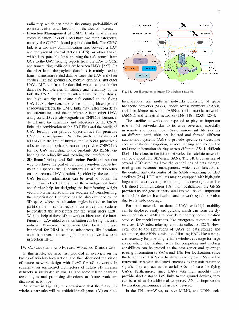
28
radio map which can predict the outage probabilities ofcommunication at all locations in the area of interest.
• Proactive Management of CNPC Links: The wirelesscommunication links of UAVs have two main categories,namely, the CNPC link and payload data link. The CNPClink is a two-way communication link between a UAVand the ground control station (GCS), or other UAVs,which is responsible for supporting the safe control fromGCS to the UAV, sending reports from the UAV to GCS,and transmitting collision alert between UAVs [227]. Onthe other hand, the payload data link is mainly used totransmit mission-related data between the UAV and otherentities, like the ground BS, mobile terminals, and otherUAVs. Different from the data link which requires higherdata rate but tolerates on latency and reliability of thelink, the CNPC link requires ultra-reliability, low latency,and high security to ensure safe control to the flyingUAV [228]. However, due to the building blockage andshadowing effects, the CNPC links may suffer from delayand attenuation, and the interference from other UAVsand ground BSs can also degrade the CNPC performance.To enhance the reliability and robustness of the CNPClinks, the combination of the 3D REMs and the predictedUAV location can provide opportunities for proactiveCNPC link management. With the predicted locations ofall UAVs in the area of interest, the GCS can proactivelyallocate the appropriate spectrum to provide CNPC linkfor the UAV according to the pre-built 3D REMs, en-hancing the reliability and reducing the interference.
• 3D Beamforming and Sub-sector Partition: Anotherway to achieve the goal of ubiquitous wireless connectiv-ity in 3D space is the 3D beamforming, which also relieson the accurate UAV location. Specifically, the accurateUAV location information can be used to obtain theazimuth and elevation angles of the aerial-ground links,and further help for designing the beamforming weightvectors. Furthermore, with the accurate 3D beamforming,the sectorization technique can be also extended to the3D space, where the elevation angles is used to furtherpartition the horizontal sector in current cellular systemsto construct the sub-sectors for the aerial users [228].With the help of these 3D network architectures, the inter-ference in UAV-aided communication can be significantlyreduced. Moreover, the accurate UAV location is alsobeneficial for RRM in these sub-sectors, like location-aided handover, multcasting, and so on, as we discussedin Section III-C.
IV. CONCLUSIONS AND FUTURE WORKING DIRECTIONS
In this article, we have first provided an overview on thebasics of wireless localization, and then discussed the visionof future network design with ILAC for 6G networks. Insummary, an envisioned architecture of future 3D wirelessnetworks is illustrated in Fig. 11, and some related enablingtechnologies and promising directions of future work arediscussed as follows.
As shown in Fig. 11, it is envisioned that the future 6Gwireless networks will be artificial intelligence (AI) enabled,
Fig. 11. An illustration of future 3D wireless networks.
heterogenous, and multi-tier networks consisting of spacebackbone networks (SBNs), space access networks (SANs),aerial backbone networks (ABNs), aerial mobile networks(AMNs), and terrestrial networks (TNs) [18], [253], [254].
The satellite networks are expected to play an importantrole in 6G networks due to its wide coverage, especiallyin remote and ocean areas. Since various satellite systemson different earth obits are isolated and formed differentautonomous systems (ASs) to provide specific services, likecommunications, navigation, remote sensing and so on, thereal-time information sharing across different ASs is difficult[254]. Therefore, in the future networks, the satellite networkscan be divided into SBNs and SANs. The SBNs consisting ofseveral GEO satellites have the capabilities of data storage,routing and resource management, which can function asthe control and data center of the SANs consisting of LEOsatellites [254]. LEO satellites may be equipped with high-gainlarge antenna arrays to provide ubiquitous coverage to enableUE direct communication [18]. For localization, the GNSSprovided by the geostationary satellites will be still importantfor mobile device localization and network synchronizationdue to its wide coverage.
For aerial networks, on-demand UAVs with high mobilitycan be deployed easily and quickly, which can form the dy-namic adjustable AMNs to provide temporary communicationservices for special missions, like emergency communicationservices, UAV-aided relaying, and data collection [227]. How-ever, due to the limitations of UAVs on data storage andendurance, the ABNs consisting of floating HAPs like airshipsare necessary for providing reliable wireless coverage for largeareas, where the airships with the computing and cachingcapabilities can be treated as the data center and gatewaysrouting information to SANs and TNs. For localization, sincethe locations of HAPs can be determined by the GNSS or theterrestrial BSs with dedicated antennas to transmit referencesignals, they can act as the aerial ANs to locate the flyingUAVs. Furthermore, since UAVs with high mobility mayprovide short-distance LoS links to the ground devices, theycan be used as the additional temporary ANs to improve thelocalization performance of ground devices.
In the TNs, mmWave, massive MIMO, and UDNs tech-
29
nologies can be combined to improve the communicationand localization performance. Furthermore, as a promisingtrend, device-centric networks will flourish the cell-free mobilecommunications, which will require high accurate cooperativelocalization among devices for resource allocation. On theother hand, the future networks will become more heteroge-nous, combining with various radio access standards, like2G/3G/LTE/5G, WiFi, as well as the Terahertz (THz) and vis-ible light frequency bands. Therefore, the integrated resourceallocation schemes and protocols are required to leveragemultiple frequencies to provide seamless wireless connectivityfor mobile devices. For localization, the system needs toselect the appropriate localization approaches and referencesignals depending on the surrounding radio environments ofthe mobile devices for better performance.
Finally, AI-enabled cloudization is a promising trend offuture wireless networks, as illustrated in Fig. 11, which can bemainly divided into RAN cloud and CN cloud. The distributedAI units deployed at the edges of the RAN assist signalreconstruction, which is beneficial for data decoding and signalmeasurements to improve communication and localizationperformance, respectively. In the CN cloud, the centralizedAI units can be used to construct the 3D REMs, whichcan be used to assist the localization scheme selection andproactive RRM for communications. As a vision of 6G, the AI-enabled networks are expected to autonomously optimize andmanage the resource to dynamically maintain communicationperformance of the UE according to its accurate real-timelocation.
However, to achieve the above visions, there are still manychallenges to be addressed. Note that while some challengeshave already been discussed in the previous sections, in thefollowing, we outline some important directions for futurework and highlight the promise of ILAC.
A. Fundamental Performance Analysis and Design for ILACAchieving ultra-high spectral efficiency is critical for fu-
ture networks, especially for the IIoT application scenarios,which require massive wireless connectivity to support reliablecommunication and accurate localization services for massiveIoT devices. To achieve ultra-high spectral efficiency forILAC, a common spectrum can be shared by localization andcommunication, or be divided into two orthogonal parts forthem. Furthermore, for shared spectrum, the signal waveformcan be jointly designed for localization and communicationsimultaneously, or two specific waveforms can be separatelydesigned. Therefore, the theoretical analysis of the fundamen-tal performance of ILAC and how to design the waveformsfor ultra-high spectral efficiency is an important problem.On the other hand, for orthogonal spectrum usage, sincelocalization and communication both benefit from wide signalbandwidth, a critical issue is that how to split the spectrumeffectively to optimize the trade-off between localization andcommunication according to different QoS requirements.
B. Advanced Signal Processing for Multi-Tier ILAC NetworksIn multi-tier networks, the mobile terminals in different lay-
ers of networks can interact in different frequency bands with
different links. In this case, how to maintain the wireless linksdynamically and effectively is a critical issue for localizationand communication. The integration of different frequencybands and dynamic resource management is a potential optionto reconfigure and maintain the wireless connections, and theeffective signal processing is an important factor for cross-layer information sharing. For ILAC, since the channel esti-mation units can be reused for location information extraction,the localization and communication systems can partly sharesome hardware, and the signal processing technologies forcommunication can be also exploited for location-related infor-mation measurements. Therefore, how to efficiently co-designthe hardware architecture and signal processing technologiesare two key questions.
C. Heterogenous Networking
The future networks are more heterogenous than before,which operate on different frequency bands with differentstandards. A fundamental question is that how to switch theprotocols rapidly from one to anther, while still ensuring thelocalization and communication performance, when the mobileterminals move quickly suffering from different radio environ-ments. For the distinct network architectures, each networklayer employs different protocols, so a natural solution is totranslate the protocols at gateways to interconnect differentnetworks. However, such a sequence of protocol translationsis inefficient, which renders the integrated protocol designthat enables cross-layer, cross-module, and cross-node datatransmission critical. Moreover, the network protocol design,especially in the physical and MAC layers, needs not only toconsider the communication metrics, but also to be re-assessedfrom the localization perspective.
D. 3D REMs and Proactive RRM in Complex Environments
The proactive RRM is beneficial for communication interms of cell selection, channel predication, beam alignmentand so on, but it will require high-accurate REMs. Currently,the studies on REMs modelling focus on the 2D scenariostargeting to the TNs in outdoor environments. As the networksextend to 3D space, 3D REMs modelling in clutter environ-ment like indoor and urban city is critical and challenging,which requires more accurate 3D localization in multi-pathand NLoS environments. Although some effective multi-pathand NLoS mitigation algorithms have been proposed in theliterature, they are usually quite complex and only feasible forremote localization systems rather than the self-localizationsystems where the computation and estimation need to bedone by UEs. On the other hand, although some studiesmainly focus on the localization in NLoS scenarios, by treatingthe signal reflectors as the virtual ANs, they are limited onthe first-order reflection for analysis simplicity, whereas thehigher-order reflections occur in dense multi-path environ-ments. Therefore, in-depth investigations on localization algo-rithms for multi-path environments are still needed for moreaccurate and low cost localization. Furthermore, how to man-age the radio resource according to the real-time location of theUE to dynamically maintain its communication performance
30
deserves further investigations. On the other hand, althoughit is well-known that the accurate location information isbeneficial for communications, the related fundamental metricsare needed to reveal the relation between different locationaccuracy and communication performance.
E. Machine Learning for ILAC
AI, or more specifically, machine learning (ML), is one ofthe most promising technologies, which can bring intelligenceto wireless networks with complext radio conditions. Dueto its capability to handle the accurate pattern recognitionfrom complex raw data, it can be used to find the networkdynamics and construct a user-centric intelligent networks,which can autonomously manage resources, functions, andnetwork control to sustain the high performance according tothe real-time location of the mobile users. For ILAC, ML canbe used in various perspectives, like waveform design, signalmodulation/coding, resource allocation, to balance the perfor-mance trade-off between localization and communication, andcreate the 3D REMs to enhance the ILAC performance.
REFERENCES
[1] TS 22.071, “Location Services (LCS); Service description; Stage 1(Release 15).”
[2] B. Zong, C. Fan, X. Wang, X. Duan, B. Wang, and J. Wang, “6Gtechnologies: key drivers, core requirements, system architectures, andenabling technologies,” IEEE Veh. Technol. Mag., vol. 14, no. 3, pp.18–27, Jul. 2019.
[3] W. Saad, M. Bennis, and M. Chen, “A vision of 6G wireless systems:applications, trends, technologies, and open research problems,” IEEENetw., pp. 1–9, Oct. 2019.
[4] E. C. Strinati, S. Barbarossa, J. L. Gonzalez-Jimenez, D. Ktenas,N. Cassiau, L. Maret, and C. Dehos, “6G: the next frontier: fromholographic messaging to artificial intelligence using subterahertz andvisible light communication,” IEEE Veh. Technol. Mag., vol. 14, no. 3,pp. 42–50, Sept. 2019.
[5] M. Latva-aho and K. Leppanen, “Key drivers and research challengesfor 6G ubiquitous wireless intelligence,” 6G Flagship, University ofOulu, Finland, Sept. 2019.
[6] L. Zhang, Y.-C. Liang, and D. Niyato, “6G visions: mobile ultra-broadband, super internet-of-things, and artificial intelligence,” ChinaCommunications, vol. 16, no. 8, pp. 1–14, Aug. 2019.
[7] FG-NET-2030, “Network 2030: a blueprint of technology, applicationsand market drivers towards the year 2030 and beyond,” Jul. 2019.
[8] M. Chen, W. Saad, and C. Yin, “Virtual reality over wireless networks:quality-of-service model and learning-based resource management,”IEEE Trans. Commun., vol. 66, no. 11, pp. 5621–5635, Nov. 2018.
[9] C.-M. Chang, C.-H. Hsu, C.-F. Hsu, and K.-T. Chen, “Performancemeasurements of virtual reality systems: quantifying the timing andpositioning accuracy,” in Proceedings of the 24th ACM InternationalConference on Multimedia, 2016, pp. 655–659.
[10] F. Tariq, M. Khandaker, K.-K. Wong, M. Imran, M. Bennis,and M. Debbah, “A speculative study on 6G,” arXiv preprintarXiv:1902.06700, 2019.
[11] K. Witrisal, S. Hinteregger, J. Kulmer, E. Leitinger, and P. Meissner,“High-accuracy positioning for indoor applications: RFID, UWB, 5G,and beyond,” in IEEE International Conference on RFID, 2016, pp.1–7.
[12] K. Witrisal, P. Meissner, E. Leitinger, Y. Shen, C. Gustafson, F. Tufves-son, K. Haneda, D. Dardari, A. F. Molisch, A. Conti et al., “High-accuracy localization for assisted living: 5G systems will turn multipathchannels from foe to friend,” IEEE Signal Process. Mag., vol. 33, no. 2,pp. 59–70, Mar. 2016.
[13] J. B. Kenney, “Dedicated short-range communications (DSRC) stan-dards in the United States,” Proceedings of the IEEE, vol. 99, no. 7,pp. 1162–1182, Jul. 2011.
[14] S. Chen, J. Hu, Y. Shi, Y. Peng, J. Fang, R. Zhao, and L. Zhao,“Vehicle-to-everything (V2X) services supported by LTE-based sys-tems and 5G,” IEEE Communications Standards Magazine, vol. 1,no. 2, pp. 70–76, Jul. 2017.
[15] Q. Mao, F. Hu, and Q. Hao, “Deep learning for intelligent wirelessnetworks: a comprehensive survey,” IEEE Commun. Surveys Tuts.,vol. 20, no. 4, pp. 2595–2621, 4th Quart. 2018.
[16] A. Asadi, Q. Wang, and V. Mancuso, “A survey on device-to-devicecommunication in cellular networks,” IEEE Commun. Surveys Tuts.,vol. 16, no. 4, pp. 1801–1819, 4th Quart. 2014.
[17] Y. Liu, X. Shi, S. He, and Z. Shi, “Prospective positioning architectureand technologies in 5G networks,” IEEE Netw., vol. 31, no. 6, pp.115–121, Nov. 2017.
[18] X. You, H. Yin, and H. Wu, “The space-terrestrial integrated network(STIN): an overview,” Chinese Journal on Internet of Things, vol. 4,no. 1, pp. 3–11, Mar. 2020.
[19] L. Hui, H. Darabi, P. Banerjee, and L. Jing, “Survey of wireless indoorpositioning techniques and systems,” IEEE Transactions on Systems,Man, and Cybernetics, Part C (Applications and Reviews), vol. 37,no. 6, pp. 1067–1080, Nov. 2007.
[20] A. Yassin, Y. Nasser, M. Awad, A. Al-Dubai, R. Liu, C. Yuen,R. Raulefs, and E. Aboutanios, “Recent advances in indoor localization:A survey on theoretical approaches and applications,” IEEE Commun.Surveys Tuts.,, vol. 19, no. 2, pp. 1327–1346, 2nd Quart. 2017.
[21] F. Zafari, A. Gkelias, and K. K. Leung, “A survey of indoor localizationsystems and technologies,” IEEE Commun. Surveys Tuts.,, vol. 21,no. 3, pp. 2568–2599, 3rd Quart. 2019.
[22] D. Dardari, P. Closas, and P. M. Djuric, “Indoor tracking: theory,methods, and technologies,” IEEE Trans. Veh. Technol., vol. 64, no. 4,pp. 1263–1278, Apr. 2015.
[23] L. Christos, M. Adriano, K. Sunwoo, L. Sangwoo, W. Lauri, andF. Carlo, “A survey of enabling technologies for network localization,tracking, and navigation,” IEEE Commun. Surveys Tuts.,, vol. 20, no. 4,pp. 3607–3644, 4th Quart. 2018.
[24] F. Gustafsson and F. Gunnarsson, “Mobile positioning using wirelessnetworks: possibilities and fundamental limitations based on availablewireless network measurements,” IEEE Signal Process. Mag., vol. 22,no. 4, pp. 41–53, Jul. 2005.
[25] G. Sun, J. Chen, W. Guo, and K. R. Liu, “Signal processing techniquesin network-aided positioning: a survey of state-of-the-art positioningdesigns,” IEEE Signal Process. Mag., vol. 22, no. 4, pp. 12–23, Jul.2005.
[26] J. A. Del Peral-Rosado, R. Raulefs, J. A. Lopez-Salcedo, and G. Seco-Granados, “Survey of cellular mobile radio localization methods: from1G to 5G,” IEEE Commun. Surveys Tuts.,, vol. 20, no. 2, pp. 1124–1148, 2nd Quart. 2018.
[27] C. Drane, M. Macnaughtan, and C. Scott, “Positioning GSM tele-phones,” IEEE Commun. Mag., vol. 36, no. 4, pp. 46–54, Apr. 1998.
[28] R. Di Taranto, S. Muppirisetty, R. Raulefs, D. Slock, T. Svensson,and H. Wymeersch, “Location-aware communications for 5G networks:how location information can improve scalability, latency, and robust-ness of 5G,” IEEE Signal Process. Mag., vol. 31, no. 6, pp. 102–112,Nov. 2014.
[29] M. Wax and T. Kailath, “Decentralized processing in sensor arrays,”IEEE Transactions on Acoustics, Speech, and Signal Processing,vol. 33, no. 5, pp. 1123–1129, Oct. 1985.
[30] A. J. Weiss, “Direct position determination of narrowband radiofrequency transmitters,” IEEE Signal Process. Lett., vol. 11, no. 5, pp.513–516, May. 2004.
[31] O. Bialer, D. Raphaeli, and A. J. Weiss, “Maximum-likelihood directposition estimation in dense multipath,” IEEE Trans. Veh. Technol.,vol. 62, no. 5, pp. 2069–2079, Jun. 2012.
[32] R. Zekavat and R. M. Buehrer, Handbook of position location: Theory,practice and advances. John Wiley & Sons, 2011, vol. 27.
[33] Z. Yang, Z. Zhou, and Y. Liu, “From RSSI to CSI: indoor localizationvia channel response,” ACM Computing Surveys (CSUR), vol. 46, no. 2,pp. 1–32, Dec. 2013.
[34] P. Kumar, L. Reddy, and S. Varma, “Distance measurement and errorestimation scheme for RSSI based localization in wireless sensor net-works,” in IEEE International Conference on Wireless Communicationand Sensor Networks (WCSN), 2009, pp. 1–4.
[35] J. Yang and Y. Chen, “Indoor localization using improved RSS-basedlateration methods,” in IEEE Global Telecommunications Conference,2009, pp. 1–6.
[36] Y.-T. Chan, W.-Y. Tsui, H.-C. So, and P.-C. Ching, “Time-of-arrivalbased localization under NLOS conditions,” IEEE Trans. Veh. Technol.,vol. 55, no. 1, pp. 17–24, Jan. 2006.

31
[37] W. Ke and L. Wu, “Constrained least squares algorithm for TOA-basedmobile location under NLOS environments,” in IEEE InternationalConference on Wireless Communications, Networking and MobileComputing, 2009, pp. 1–4.
[38] I. Guvenc and C.-C. Chong, “A survey on TOA based wirelesslocalization and NLOS mitigation techniques,” IEEE Commun. SurveysTuts., vol. 11, no. 3, pp. 107–124, 3rd Quart. 2009.
[39] A. Ledergerber, M. Hamer, and R. D’Andrea, “A robot self-localizationsystem using one-way ultra-wideband communication,” in IEEE/RSJInternational Conference on Intelligent Robots and Systems (IROS),2015, pp. 3131–3137.
[40] A. A. Wahab, A. Khattab, and Y. A. Fahmy, “Two-way TOA withlimited dead reckoning for GPS-free vehicle localization using singleRSU,” in IEEE International Conference on ITS Telecommunications(ITST), 2013, pp. 244–249.
[41] R. Kaune, J. Horst, and W. Koch, “Accuracy analysis for TDOAlocalization in sensor networks,” in IEEE International Conference onInformation Fusion, 2011, pp. 1–8.
[42] S.-Y. Jung, S. Hann, and C.-S. Park, “TDOA-based optical wirelessindoor localization using LED ceiling lamps,” IEEE Transactions onConsumer Electronics, vol. 57, no. 4, pp. 1592–1597, Nov. 2011.
[43] R. Kaune, “Accuracy studies for TDOA and TOA localization,” in IEEEInternational Conference on Information Fusion, 2012, pp. 408–415.
[44] S. Kumar, S. Gil, D. Katabi, and D. Rus, “Accurate indoor localizationwith zero start-up cost,” in Proceedings of the 20th annual InternationalConference on Mobile Computing and Networking, 2014, pp. 483–494.
[45] Y. Wang and K. Ho, “An asymptotically efficient estimator in closed-form for 3-D AOA localization using a sensor network,” IEEE Trans.Wirel. Commun., vol. 14, no. 12, pp. 6524–6535, Dec. 2015.
[46] M. Hata, “Empirical formula for propagation loss in land mobile radioservices,” IEEE Trans. Veh. Technol., vol. 29, no. 3, pp. 317–325, Aug.1980.
[47] C. Feng, W. S. A. Au, S. Valaee, and Z. Tan, “Received-signal-strength-based indoor positioning using compressive sensing,” IEEE Trans. Mob.Comput., vol. 11, no. 12, pp. 1983–1993, Dec. 2012.
[48] V. Honkavirta, T. Perala, S. Ali-Loytty, and R. Piche, “A comparativesurvey of WLAN location fingerprinting methods,” in IEEE Workshopon positioning, navigation and communication, 2009, pp. 243–251.
[49] C. Yang and H.-R. Shao, “WiFi-based indoor positioning,” IEEECommun. Mag., vol. 53, no. 3, pp. 150–157, Mar. 2015.
[50] Q. D. Vo and P. De, “A survey of fingerprint-based outdoor localiza-tion,” IEEE Commun. Surveys Tuts.,, vol. 18, no. 1, pp. 491–506, 1stQuart. 2015.
[51] S. He and S.-H. G. Chan, “Wi-Fi fingerprint-based indoor positioning:Recent advances and comparisons,” IEEE Commun. Surveys Tuts.,,vol. 18, no. 1, pp. 466–490, 1st Quart. 2016.
[52] A. Khalajmehrabadi, N. Gatsis, and D. Akopian, “Modern WLANfingerprinting indoor positioning methods and deployment challenges,”IEEE Commun. Surveys Tuts.,, vol. 19, no. 3, pp. 1974–2002, 3rd Quart.2017.
[53] P. Bahl and V. N. Padmanabhan, “RADAR: an in-building RF-baseduser location and tracking system,” in Proceedings IEEE INFOCOM2000. Conference on Computer Communications. Nineteenth AnnualJoint Conference of the IEEE Computer and Communications Societies,vol. 2, 2000, pp. 775–784.
[54] F. Seco, A. R. Jimenez, C. Prieto, J. Roa, and K. Koutsou, “A survey ofmathematical methods for indoor localization,” in IEEE InternationalSymposium on Intelligent Signal Processing, 2009, pp. 9–14.
[55] P. Brida, J. Duha, and M. Krasnovsky, “On the accuracy of weightedproximity based localization in wireless sensor networks,” in PersonalWireless Communications, vol. 245, 2007, pp. 423–432.
[56] T. He, C. Huang, B. M. Blum, J. A. Stankovic, and T. Abdelzaher,“Range-free localization schemes for large scale sensor networks,” inProceedings of the 9th annual International Conference on MobileComputing and Networking, 2003, pp. 81–95.
[57] M. Li and Y. Liu, “Rendered path: range-free localization in anisotropicsensor networks with holes,” Proceedings of the 13th annual Interna-tional Conference on Mobile Computing and Networking, vol. 18, no. 1,pp. 320–332, 2009.
[58] Y.-T. Chan, H. Y. C. Hang, and P.-c. Ching, “Exact and approximatemaximum likelihood localization algorithms,” IEEE Trans. Veh. Tech-nol., vol. 55, no. 1, pp. 10–16, Jan. 2006.
[59] C. Chang and A. Sahai, “Estimation bounds for localization,” in IEEEFirst Annual Communications Society Conference on Sensor and AdHoc Communications and Networks, 2004, pp. 415–424.
[60] Y. Shen and M. Z. Win, “Fundamental limits of wideband localiza-tionłPart I: A general framework,” IEEE Trans. Inf. Theory, vol. 56,no. 10, pp. 4956–4980, Oct. 2010.
[61] Y. Shen, H. Wymeersch, and M. Z. Win, “Fundamental limits ofwideband localizationłPart II: Cooperative networks,” IEEE Trans. Inf.Theory, vol. 56, no. 10, pp. 4981–5000, Oct, 2010.
[62] M. Marks and E. Niewiadomska-Szynkiewicz, “Two-phase stochasticoptimization to sensor network localization,” in IEEE InternationalConference on Sensor Technologies and Applications, 2007, pp. 134–139.
[63] P.-J. Chuang and C.-P. Wu, “An effective PSO-based node local-ization scheme for wireless sensor networks,” in IEEE InternationalConference on Parallel and Distributed Computing, Applications andTechnologies, 2008, pp. 187–194.
[64] K. K. Saab and S. S. Saab, “Application of an optimal stochasticNewton-Raphson technique to triangulation-based localization sys-tems,” in IEEE/ION Position, Location and Navigation Symposium(PLANS), 2016, pp. 981–986.
[65] B. Bejar, P. Belanovic, and S. Zazo, “Distributed Gauss-Newton methodfor localization in Ad-Hoc networks,” in IEEE Conference Recordof the Forty Fourth Asilomar Conference on Signals, Systems andComputers, 2010, pp. 1452–1454.
[66] D. J. Torrieri, “Statistical theory of passive location systems,” IEEETransactions on Aerospace and Electronic Systems, no. 2, pp. 183–198, Mar. 1984.
[67] J. Caffery, “A new approach to the geometry of TOA location,” in IEEEVehicular Technology Conference Fall, vol. 4, 2000, pp. 1943–1949.
[68] Y. Chan and K. Ho, “A simple and efficient estimator for hyperboliclocation,” IEEE Trans. Signal Process., vol. 42, no. 8, pp. 1905–1915,Aug. 1994.
[69] B. Fang, “Simple solutions for hyperbolic and related position fixes,”IEEE Transactions on Aerospace and Electronic Systems, vol. 26, no. 5,pp. 748–753, Sep. 1990.
[70] S. Nardone and M. Graham, “A closed-form solution to bearings-onlytarget motion analysis,” IEEE Journal of Oceanic Engineering, vol. 22,no. 1, pp. 168–178, Jan. 1997.
[71] M. Gavish and A. Weiss, “Performance analysis of bearing-only targetlocation algorithms,” IEEE Transactions on Aerospace and ElectronicSystems, vol. 28, no. 3, pp. 817–828, Jul. 1992.
[72] J. C. Chen, R. E. Hudson, and K. Yao, “Maximum-likelihood sourcelocalization and unknown sensor location estimation for widebandsignals in the near field,” IEEE Trans. Signal Process., vol. 50, no. 8,pp. 1843–1854, Aug. 2002.
[73] W. Navidi, W. S. Murphy, and W. Hereman, “Statistical methods insurveying by trilateration,” Computational Statistics & Data Analysis,vol. 27, no. 2, pp. 209–227, Apr. 1998.
[74] J.-Y. Lee and R. A. Scholtz, “Ranging in a dense multipath environmentusing an UWB radio link,” IEEE J. Sel. Areas Commun., vol. 20, no. 9,pp. 1677–1683, Dec. 2002.
[75] B. Denis, J. Keignart, and N. Daniele, “Impact of NLOS propagationupon ranging precision in UWB systems,” in IEEE Conference on UltraWideband Systems and Technologies, 2003, pp. 379–383.
[76] K. Witrisal, P. Meissner, E. Leitinger, Y. Shen, C. Gustafson, F. Tufves-son, K. Haneda, D. Dardari, A. F. Molisch, A. Conti et al., “High-accuracy localization for assisted living: 5G systems will turn multipathchannels from foe to friend,” IEEE Signal Process. Mag., vol. 33, no. 2,pp. 59–70, Mar. 2016.
[77] C. Gentner, T. Jost, W. Wang, S. Zhang, A. Dammann, and U.-C.Fiebig, “Multipath assisted positioning with simultaneous localizationand mapping,” IEEE Trans. Wirel. Commun., vol. 15, no. 9, pp. 6104–6117, Sept. 2016.
[78] F. Gustafsson, Statistical sensor fusion. Lund, Sweden: Studentlitter-atur, 2010.
[79] F. Gunnarsson, F. Lindsten, and N. Carlsson, “Particle filtering fornetwork-based positioning terrestrial radio networks,” in IET Confer-ence on Data Fusion & Target Tracking: Algorithms and Applications,2014, pp. 1–7.
[80] J. Dauwels, “Computing bayesian cramer-rao bounds,” in IEEE Inter-national Symposium on Information Theory, 2005, pp. 425–429.
[81] E. Weinstein and A. J. Weiss, “A general class of lower bounds inparameter estimation,” IEEE Trans. Inf. Theory, vol. 34, no. 2, pp.338–342, Mar. 1988.
[82] A. Zeira and P. M. Schultheiss, “Realizable lower bounds for time delayestimation. 2. Threshold phenomena,” IEEE Trans. Signal Process.,vol. 42, no. 5, pp. 1001–1007, May 1994.

32
[83] C. Gioia and D. Borio, “Stand-alone and hybrid positioning usingasynchronous pseudolites,” Sensors, vol. 15, no. 1, pp. 166–193, Dec.2015.
[84] P. J. Duffett-Smith and B. Tarlow, “E-GPS: indoor mobile phonepositioning on GSM and WCDMA,” in Proceedings of the 18thInternational Technical Meeting of the Satellite Division of The Instituteof Navigation, Sep. 2005, pp. 2762–2768.
[85] T. S. Rappaport, J. H. Reed, and B. D. Woerner, “Position locationusing wireless communications on highways of the future,” IEEECommun. Mag., vol. 34, no. 10, pp. 33–41, Oct. 1996.
[86] M. A. Spirito, S. Poykko, and O. Knuuttila, “Experimental performanceof methods to estimate the location of legacy handsets in GSM,” inIEEE Vehicular Technology Conference Fall, vol. 4, 2001, pp. 2716–2720.
[87] D.-B. Lin and R.-T. Juang, “Mobile location estimation based ondifferences of signal attenuations for GSM systems,” IEEE Trans. Veh.Technol., vol. 54, no. 4, pp. 1447–1454, Jul. 2005.
[88] J. Borkowski, J. Niemela, and J. Lempiainen, “Enhanced performanceof Cell ID+ RTT by implementing forced soft handover algorithm,” inIEEE Vehicular Technology Conference Fall, vol. 5, 2004, pp. 3545–3549.
[89] A. Ghosh, R. Ratasuk, B. Mondal, N. Mangalvedhe, and T. Thomas,“LTE-advanced: next-generation wireless broadband technology,” IEEEWirel. Commun., vol. 17, no. 3, pp. 10–22, Jun. 2010.
[90] J. Sadowski, “TDOA navigation using CDMA2000 signals–Experimental results,” in IEEE Ubiquitous Positioning IndoorNavigation and Location Based Service (UPINLBS), 2014, pp.265–271.
[91] J. A. del Peral-Rosado, J. A. Lopez-Salcedo, G. Seco-Granados,F. Zanier, and M. Crisci, “Joint maximum likelihood time-delay esti-mation for LTE positioning in multipath channels,” EURASIP Journalon Advances in Signal Processing, vol. 2014, no. 1, pp. 1–13, Mar.2014.
[92] M. Driusso, F. Babich, F. Knutti, M. Sabathy, and C. Marshall,“Estimation and tracking of LTE signals time of arrival in a mobilemultipath environment,” in International Symposium on Image andSignal Processing and Analysis (ISPA), 2015, pp. 276–281.
[93] S. S. Cherian and A. N. Rudrapatna, “LTE location technologies anddelivery solutions,” Bell Labs Tech. J., vol. 18, no. 2, pp. 175–194,Sep. 2013.
[94] TS 36.355, “Evolved Universal Terrestrial Radio Access (E-UTRA);LTE Positioning Protocol (LPP) (Release 9).”
[95] Ericsson White Paper, “Positioning with LTE,” 2011.[96] M. Centenaro, L. Vangelista, A. Zanella, and M. Zorzi, “Long-range
communications in unlicensed bands: the rising stars in the IoT andsmart city scenarios,” IEEE Wirel. Commun., vol. 23, no. 5, pp. 60–67,Oct. 2016.
[97] H. Liu, Y. Gan, J. Yang, S. Sidhom, Y. Wang, Y. Chen, and F. Ye, “Pushthe limit of WiFi based localization for smartphones,” in Proceedings ofthe 18th annual ACM International Conference on Mobile Computingand Networking, 2012, pp. 305–316.
[98] H.-H. Liu and Y.-N. Yang, “WiFi-based indoor positioning for multi-floor environment,” in TENCON 2011-2011 IEEE Region 10 Confer-ence, 2011, pp. 597–601.
[99] P. Davidson and R. Piche, “A survey of selected indoor positioningmethods for smartphones,” IEEE Commun. Surveys Tuts., vol. 19, no. 2,pp. 1347–1370, 2nd Quart. 2017.
[100] H. Zou, H. Jiang, X. Lu, and L. Xie, “An online sequential extremelearning machine approach to WiFi based indoor positioning,” in IEEEWorld Forum on Internet of Things (WF-IoT), 2014, pp. 111–116.
[101] M. Kotaru, K. Joshi, D. Bharadia, and S. Katti, “Spotfi: decimeter levellocalization using WiFi,” in Proceedings of the 2015 ACM Conferenceon Special Interest Group on Data Communication, 2015, pp. 269–282.
[102] I. Oppermann, M. Hamalainen, and J. Iinatti, UWB: theory andapplications. John Wiley & Sons, 2005.
[103] Z. Sahinoglu, S. Gezici, and I. Guvenc, Ultra-wideband positioningsystems. Cambridge, U.K.: Cambridge Univ. Press, 2008.
[104] S. Gezici, Z. Tian, G. B. Giannakis, H. Kobayashi, A. F. Molisch,H. V. Poor, and Z. Sahinoglu, “Localization via ultra-wideband radios:a look at positioning aspects for future sensor networks,” IEEE SignalProcess. Mag., vol. 22, no. 4, pp. 70–84, Jul. 2005.
[105] Z. W. Mekonnen, E. Slottke, H. Luecken, C. Steiner, and A. Wittneben,“Constrained maximum likelihood positioning for UWB based humanmotion tracking,” in IEEE International Conference on Indoor Posi-tioning and Indoor Navigation, 2010, pp. 1–10.
[106] A. Alarifi, A. Al-Salman, M. Alsaleh, A. Alnafessah, S. Al-Hadhrami,M. A. Al-Ammar, and H. S. Al-Khalifa, “Ultra wideband indoor posi-tioning technologies: Analysis and recent advances,” Sensors, vol. 16,no. 5, p. 707, Mar. 2016.
[107] H. Durrant-Whyte and T. Bailey, “Simultaneous localisation and map-ping (SLAM): part I the essential algorithms,” IEEE Robot. Autom.Mag., vol. 13, no. 2, pp. 99–110, Jun. 2006.
[108] T. Bailey and H. Durrant-Whyte, “Simultaneous localization and map-ping (SLAM): part II state of the art,” IEEE Robot. Autom. Mag.,vol. 13, no. 3, pp. 108–117, Sep. 2006.
[109] C. Cadena, L. Carlone, H. Carrillo, Y. Latif, D. Scaramuzza, J. Neira,I. Reid, and J. J. Leonard, “Past, present, and future of simultaneouslocalization and mapping: toward the robust-perception age,” IEEETrans. Robot., vol. 32, no. 6, pp. 1309–1332, Dec. 2016.
[110] N. Patwari, J. N. Ash, S. Kyperountas, A. O. Hero, R. L. Moses, andN. S. Correal, “Locating the nodes: cooperative localization in wirelesssensor networks,” IEEE Signal Process. Mag., vol. 22, no. 4, pp. 54–69,Jul. 2005.
[111] G. Mao, B. Fidan, and B. D. Anderson, “Wireless sensor networklocalization techniques,” Comput. Netw., vol. 51, no. 10, pp. 2529–2553, Jul. 2007.
[112] H. Wymeersch, J. Lien, and M. Z. Win, “Cooperative localization inwireless networks,” Proceedings of the IEEE, vol. 97, no. 2, pp. 427–450, Feb. 2009.
[113] D. Niculescu and B. Nath, “Ad hoc positioning system (APS),” in IEEEGlobal Telecommunications Conference, vol. 5, 2001, pp. 2926–2931.
[114] Y. Shang, W. Rumi, Y. Zhang, and M. Fromherz, “Localization fromconnectivity in sensor networks,” IEEE Transactions on Parallel andDistributed Systems, vol. 15, no. 11, pp. 961–974, Nov. 2004.
[115] V. Vivekanandan and V. W. Wong, “Concentric anchor beacon lo-calization algorithm for wireless sensor networks,” IEEE Trans. Veh.Technol., vol. 56, no. 5, pp. 2733–2744, Sept. 2007.
[116] A. T. Ihler, J. W. Fisher, R. L. Moses, and A. S. Willsky, “Nonparamet-ric belief propagation for self-localization of sensor networks,” IEEEJ. Sel. Areas. Commun., vol. 23, no. 4, pp. 809–819, Apr. 2005.
[117] K. Radnosrati, F. Gunnarsson, and F. Gustafsson, “New trends in radionetwork positioning,” in IEEE International Conference on InformationFusion (Fusion), 2015, pp. 492–498.
[118] A. De Angelis and C. Fischione, “Mobile node localization via Paretooptimization: Algorithm and fundamental performance limitations,”IEEE J. Sel. Areas. Commun., vol. 33, no. 7, pp. 1288–1303, Jul.
[119] J. B. Bullock, M. Chowdhary, D. Rubin, D. Leimer, G. Turetzky, andM. Jarvis, “Continuous indoor positioning using GNSS, Wi-Fi, andMEMS dead reckoning,” in Proceedings of the 25th International Tech-nical Meeting of The Satellite Division of the Institute of Navigation(ION GNSS 2012), 2012, pp. 2408–2416.
[120] M. Series, “IMT vision–framework and overall objectives of the futuredevelopment of IMT for 2020 and beyond,” Recommendation ITU, pp.2083–0, Sep.
[121] R. Keating, M. Saily, J. Hulkkonen, and J. Karjalainen, “Overview ofpositioning in 5G new radio,” in International Symposium on WirelessCommunication Systems (ISWCS), 2019, pp. 320–324.
[122] TR 22.872, “Study on Positioning Use Cases; Stage 1 (Release 16).”[123] TR 38.855, “Study on NR positioning support (Release 16).”[124] TR 22.804, “Study on Communication for Automation in Vertical
domains (CAV) (Release 15).”[125] R. W. Heath, N. Gonzalez-Prelcic, S. Rangan, W. Roh, and A. M.
Sayeed, “An overview of signal processing techniques for millimeterwave MIMO systems,” IEEE Journal of Selected Topics in SignalProcessing, vol. 10, no. 3, pp. 436–453, Apr. 2016.
[126] F. Lemic, J. Martin, C. Yarp, D. Chan, V. Handziski, R. Brodersen,G. Fettweis, A. Wolisz, and J. Wawrzynek, “Localization as a featureof mmwave communication,” in IEEE International Wireless Communi-cations and Mobile Computing Conference (IWCMC), 2016, pp. 1033–1038.
[127] E. G. Larsson, O. Edfors, F. Tufvesson, and T. L. Marzetta, “MassiveMIMO for next generation wireless systems,” IEEE Commun. Mag.,vol. 52, no. 2, pp. 186–195, Feb. 2014.
[128] F. Rusek, D. Persson, B. K. Lau, E. G. Larsson, T. L. Marzetta,O. Edfors, and F. Tufvesson, “Scaling up MIMO: opportunities andchallenges with very large arrays,” IEEE Signal Process. Mag., vol. 30,no. 1, pp. 40–60, Jan. 2013.
[129] L. Lu, G. Y. Li, A. L. Swindlehurst, A. Ashikhmin, and R. Zhang, “Anoverview of massive MIMO: benefits and challenges,” IEEE Journalof Selected Topics in Signal Processing, vol. 8, no. 5, pp. 742–758,Oct. 2014.

33
[130] V. Jungnickel, K. Manolakis, W. Zirwas, B. Panzner, V. Braun,M. Lossow, M. Sternad, R. Apelfrojd, and T. Svensson, “The role ofsmall cells, coordinated multipoint, and massive MIMO in 5G,” IEEECommun. Mag., vol. 52, no. 5, pp. 44–51, May 2014.
[131] A. Shahmansoori, G. E. Garcia, G. Destino, G. Seco-Granados, andH. Wymeersch, “5G position and orientation estimation through mil-limeter wave MIMO,” in IEEE Globecom Workshops (GC Wkshps),2015, pp. 1–6.
[132] Z. Abu-Shaban, X. Zhou, T. Abhayapala, G. Seco-Granados, andH. Wymeersch, “Error bounds for uplink and downlink 3D localizationin 5G millimeter wave systems,” IEEE Trans. Wirel. Commun., vol. 17,no. 8, pp. 4939–4954, Aug. 2018.
[133] S. Sur, V. Venkateswaran, X. Zhang, and P. Ramanathan, “60 GHzindoor networking through flexible beams: A link-level profiling,” inProceedings of the 2015 ACM SIGMETRICS International Conferenceon Measurement and Modeling of Computer Systems, 2015, pp. 71–84.
[134] E. Perahia, C. Cordeiro, M. Park, and L. L. Yang, “IEEE 802.11 ad:defining the next generation multi-Gbps Wi-Fi,” in IEEE ConsumerCommunications and Networking Conference, 2010, pp. 1–5.
[135] T. Baykas, C.-S. Sum, Z. Lan, J. Wang, M. A. Rahman, H. Harada, andS. Kato, “IEEE 802.15. 3c: the first IEEE wireless standard for datarates over 1 Gb/s,” IEEE Commun. Mag., vol. 49, no. 7, pp. 114–121,Jul. 2011.
[136] S. Singh, R. Mudumbai, and U. Madhow, “Interference analysis forhighly directional 60-GHz mesh networks: the case for rethinkingmedium access control,” IEEE/ACM Trans. Netw., vol. 19, no. 5, pp.1513–1527, Oct. 2011.
[137] H. Deng and A. Sayeed, “Mm-wave MIMO channel modeling anduser localization using sparse beamspace signatures,” in IEEE 15thInternational Workshop on Signal Processing Advances in WirelessCommunications (SPAWC), 2014, pp. 130–134.
[138] J. Saloranta and G. Destino, “On the utilization of MIMO-OFDM chan-nel sparsity for accurate positioning,” in European Signal ProcessingConference (EUSIPCO), 2016, pp. 748–752.
[139] Z. Qingling and J. Li, “Rain attenuation in millimeter wave ranges,”in IEEE International Symposium on Antennas, Propagation & EMTheory, 2006, pp. 1–4.
[140] Y. Zeng and R. Zhang, “Millimeter wave MIMO with lens antennaarray: a new path division multiplexing paradigm,” IEEE Trans. Com-mun., vol. 64, no. 4, pp. 1557–1571, Apr. 2016.
[141] Y. U. Lee, J. Choi, I. Song, and S. R. Lee, “Distributed source modelingand direction-of-arrival estimation techniques,” IEEE Trans. SignalProcess., vol. 45, no. 4, pp. 960–969, Apr. 1997.
[142] D. Astely and B. Ottersten, “The effects of local scattering on directionof arrival estimation with MUSIC,” IEEE Trans. Signal Process.,vol. 47, no. 12, pp. 3220–3234, Dec. 1999.
[143] L. Wan, G. Han, J. Jiang, J. J. Rodrigues, N. Feng, and T. Zhu, “DOAestimation for coherently distributed sources considering circular andnoncircular signals in massive MIMO systems,” IEEE Systems Journal,vol. 11, no. 1, pp. 41–49, Mar. 2015.
[144] A. Hu, T. Lv, H. Gao, Z. Zhang, and S. Yang, “An ESPRIT-basedapproach for 2-D localization of incoherently distributed sources inmassive MIMO systems,” IEEE Journal of Selected Topics in SignalProcessing, vol. 8, no. 5, pp. 996–1011, Oct. 2014.
[145] F. Wen, H. Wymeersch, B. Peng, W. P. Tay, H. C. So, and D. Yang, “Asurvey on 5G massive MIMO localization,” Digital Signal Processing,vol. 94, pp. 21–28, Nov. 2019.
[146] M. Haardt, M. Pesavento, F. Roemer, and M. N. El Korso, “Subspacemethods and exploitation of special array structures,” vol. 3, pp. 651–717, 2014.
[147] C.-R. Tsai, Y.-H. Liu, and A.-Y. Wu, “Efficient compressive channelestimation for millimeter-wave large-scale antenna systems,” IEEETrans. Signal Process., vol. 66, no. 9, pp. 2414–2428, May 2018.
[148] S. Valaee, B. Champagne, and P. Kabal, “Parametric localization ofdistributed sources,” IEEE Trans. Signal Process., vol. 43, no. 9, pp.2144–2153, Sept. 1995.
[149] S. Shahbazpanahi, S. Valaee, and M. H. Bastani, “Distributed sourcelocalization using ESPRIT algorithm,” IEEE Trans. Signal Process.,vol. 49, no. 10, pp. 2169–2178, Oct. 2001.
[150] J. Lee, I. Song, H. Kwon, and S. R. Lee, “Low-complexity estimation of2D DOA for coherently distributed sources,” Signal Process., vol. 83,no. 8, pp. 1789–1802, Aug. 2003.
[151] T. Trump and B. Ottersten, “Estimation of nominal direction of arrivaland angular spread using an array of sensors,” Signal Process., vol. 50,no. 1-2, pp. 57–69, Apr. 1996.
[152] B. Ottersten, P. Stoica, and R. Roy, “Covariance matching estimationtechniques for array signal processing applications,” Digital SignalProcess., vol. 8, no. 3, pp. 185–210, Jul. 1998.
[153] A. Zoubir, Y. Wang, and P. Charge, “Efficient subspace-based estimatorfor localization of multiple incoherently distributed sources,” IEEETrans. Signal Process., vol. 56, no. 2, pp. 532–542, Feb. 2008.
[154] M. Tapio, “Direction and spread estimation of spatially distributedsignals via the power azimuth spectrum,” in IEEE International Con-ference on Acoustics, Speech, and Signal Processing, vol. 3, 2002, pp.3005–3008.
[155] J. Yang, S. Jin, Y. Han, M. Matthaiou, and Y. Zhu, “3-D position andvelocity estimation in 5G mmwave CRAN with lens antenna arrays,”in IEEE Vehicular Technology Conference Fall, 2019, pp. 1–6.
[156] J. Yang, S. Jin, C.-K. Wen, J. Guo, and M. Matthaiou, “3-D positioningand environment mapping for mmwave communication systems,” arXivpreprint arXiv:1908.04142, 2019.
[157] M. Vari and D. Cassioli, “mmwaves rssi indoor network localization,”in IEEE International Conference on Communications Workshops(ICC), 2014, pp. 127–132.
[158] T. Wei and X. Zhang, “mtrack: High-precision passive tracking usingmillimeter wave radios,” in Proceedings of the 21st Annual Interna-tional Conference on Mobile Computing and Networking, 2015, pp.117–129.
[159] A. Shahmansoori, G. E. Garcia, G. Destino, G. Seco-Granados,and H. Wymeersch, “Position and orientation estimation throughmillimeter-wave MIMO in 5G systems,” IEEE Trans. Wirel. Commun.,vol. 17, no. 3, pp. 1822–1835, Mar. 2018.
[160] J. Li, J. Conan, and S. Pierre, “Position location of mobile terminal inwireless MIMO communication systems,” IEEE Journal of Communi-cations and Networks, vol. 9, no. 3, pp. 254–264, Sept. 2007.
[161] V. Savic and E. G. Larsson, “Fingerprinting-based positioning indistributed massive MIMO systems,” in IEEE Vehicular TechnologyConference Fall, 2015, pp. 1–5.
[162] N. Garcia, H. Wymeersch, E. G. Larsson, A. M. Haimovich, andM. Coulon, “Direct localization for massive MIMO,” IEEE Trans.Signal Process., vol. 65, no. 10, pp. 2475–2487, May 2017.
[163] M. Koivisto, M. Costa, J. Werner, K. Heiska, J. Talvitie, K. Leppanen,V. Koivunen, and M. Valkama, “Joint device positioning and clocksynchronization in 5G ultra-dense networks,” IEEE Trans. Wirel. Com-mun., vol. 16, no. 5, pp. 2866–2881, May 2017.
[164] M. Koivisto, A. Hakkarainen, M. Costa, P. Kela, K. Leppanen, andM. Valkama, “High-efficiency device positioning and location-awarecommunications in dense 5G networks,” IEEE Commun. Mag., vol. 55,no. 8, pp. 188–195, Aug. 2017.
[165] H. Wymeersch, G. Seco-Granados, G. Destino, D. Dardari, andF. Tufvesson, “5G mmWave positioning for vehicular networks,” IEEEWirel. Commun., vol. 24, no. 6, pp. 80–86, Dec. 2017.
[166] F. Boccardi, R. W. Heath, A. Lozano, T. L. Marzetta, and P. Popovski,“Five disruptive technology directions for 5G,” IEEE Commun. Mag.,vol. 52, no. 2, pp. 74–80, Feb. 2014.
[167] Y.-D. Lin and Y.-C. Hsu, “Multihop cellular: a new architecture forwireless communications,” in Proceedings IEEE INFOCOM 2000.Conference on Computer Communications. Nineteenth Annual JointConference of the IEEE Computer and Communications Societies,vol. 3, 2000, pp. 1273–1282.
[168] L. Lei, Z. Zhong, C. Lin, and X. Shen, “Operator controlled device-to-device communications in LTE-advanced networks,” IEEE Wirel.Commun., vol. 19, no. 3, pp. 96–104, Jun. 2012.
[169] N. K. Pratas and P. Popovski, “Low-rate machine-type communi-cation via wireless device-to-device (D2D) links,” arXiv preprintarXiv:1305.6783, 2013.
[170] X. Bao, U. Lee, I. Rimac, and R. R. Choudhury, “Dataspotting: offload-ing cellular traffic via managed device-to-device data transfer at dataspots,” ACM SIGMOBILE Mobile Computing and CommunicationsReview, vol. 14, no. 3, pp. 37–39, Dec. 2010.
[171] M. N. Tehrani, M. Uysal, and H. Yanikomeroglu, “Device-to-devicecommunication in 5G cellular networks: challenges, solutions, andfuture directions,” IEEE Commun. Mag., vol. 52, no. 5, pp. 86–92,May 2014.
[172] R. Baldemair, T. Irnich, K. Balachandran, E. Dahlman, G. Mildh,Y. Selen, S. Parkvall, M. Meyer, and A. Osseiran, “Ultra-dense net-works in millimeter-wave frequencies,” IEEE Commun. Mag., vol. 53,no. 1, pp. 202–208, Jan. 2015.
[173] M. Kamel, W. Hamouda, and A. Youssef, “Ultra-dense networks: Asurvey,” IEEE Commun. Surveys Tuts., vol. 18, no. 4, pp. 2522–2545,4th Quart. 2016.

34
[174] M. Ding, D. Lopez-Perez, G. Mao, P. Wang, and Z. Lin, “Will thearea spectral efficiency monotonically grow as small cells go dense?”in IEEE Global Communications Conference (GLOBECOM), 2015, pp.1–7.
[175] J. Werner, M. Costa, A. Hakkarainen, K. Leppanen, and M. Valkama,“Joint user node positioning and clock offset estimation in 5Gultra-dense networks,” in IEEE Global Communications Conference(GLOBECOM), 2015, pp. 1–7.
[176] M. Koivisto, J. Talvitie, M. Costa, K. Leppanen, and M. Valkama,“Joint cmWave-based multiuser positioning and network synchroniza-tion in dense 5G networks,” in IEEE Wireless Communications andNetworking Conference (WCNC), 2018, pp. 1–6.
[177] H. Celebi and H. Arslan, “Utilization of location information incognitive wireless networks,” IEEE Wirel. Commun., vol. 14, no. 4,pp. 6–13, Aug. 2007.
[178] D. Slock, “Location aided wireless communications,” in InternationalSymposium on Communications, Control and Signal Processing, 2012,pp. 1–6.
[179] A. Dammann, G. Agapiou, J. Bastos, L. Brunelk, M. Garcia, J. Guillet,Y. Ma, J. Ma, J. J. Nielsen, L. Ping et al., “WHERE2 location aidedcommunications,” in European Wireless Conference, 2013, pp. 1–8.
[180] P. Kela, M. Costa, J. Turkka, M. Koivisto, J. Werner, A. Hakkarainen,M. Valkama, R. Jantti, and K. Leppanen, “Location based beamformingin 5G ultra-dense networks,” in IEEE Vehicular Technology ConferenceFall, 2016, pp. 1–7.
[181] N. Garcia, H. Wymeersch, E. G. Strom, and D. Slock, “Location-aided mm-wave channel estimation for vehicular communication,” inIEEE 17th International Workshop on Signal Processing Advances inWireless Communications (SPAWC), 2016, pp. 1–5.
[182] A. Abdelreheem, E. M. Mohamed, and H. Esmaiel, “Millimeter wavelocation-based beamforming using compressive sensing,” in IEEE 28thInternational Conference on Microelectronics (ICM), 2016, pp. 213–216.
[183] ——, “Location-based millimeter wave multi-level beamforming usingcompressive sensing,” IEEE Commun. Lett., vol. 22, no. 1, pp. 185–188, Jan. 2018.
[184] H. B. Yilmaz, T. Tugcu, F. Alagoz, and S. Bayhan, “Radio environmentmap as enabler for practical cognitive radio networks,” IEEE Commun.Mag., vol. 51, no. 12, pp. 162–169, Dec. 2013.
[185] S. Bi, J. Lyu, Z. Ding, and R. Zhang, “Engineering radio map forwireless resource management,,” IEEE Wirel. Commun., vol. 26, no. 2,pp. 133–141, Apr. 2019.
[186] Y. Zeng, X. Xu, S. Jin, and R. Zhang, “Simultaneous navigation andradio mapping for cellular-connected UAV with deep reinforcementlearning,” arXiv preprint arXiv:2003.07574, 2020.
[187] S. Ureten, A. Yongacoglu, and E. Petriu, “A comparison of interferencecartography generation techniques in cognitive radio networks,” inIEEE International Conference on Communications (ICC), 2012, pp.1879–1883.
[188] H. B. Yilmaz and T. Tugcu, “Location estimation-based radio envi-ronment map construction in fading channels,” Wirel. Commun. Mob.Comput., vol. 15, no. 3, pp. 561–570, Mar. 2015.
[189] I. Nevat, G. W. Peters, and I. B. Collings, “Location-aware cooperativespectrum sensing via Gaussian processes,” in Australian Communica-tions Theory Workshop (AusCTW), 2012, pp. 19–24.
[190] S. Sand, R. Tanbourgi, C. Mensing, and R. Raulefs, “Position awareadaptive communication systems,” in IEEE Conference Record of theForty-Third Asilomar Conference on Signals, Systems and Computers,2009, pp. 73–77.
[191] A. Hakkarainen, J. Werner, M. Costa, K. Leppanen, and M. Valkama,“High-efficiency device localization in 5G ultra-dense networks:prospects and enabling technologies,” in IEEE Vehicular TechnologyConference Fall, 2015, pp. 1–5.
[192] R. Irmer, H. Droste, P. Marsch, M. Grieger, G. Fettweis, S. Brueck,H.-P. Mayer, L. Thiele, and V. Jungnickel, “Coordinated multipoint:concepts, performance, and field trial results,” IEEE Commun. Mag.,vol. 49, no. 2, pp. 102–111, Feb. 2011.
[193] Y.-B. Ko and N. H. Vaidya, “Location-Aided Routing (LAR) in mobilead hoc networks,” Wirel. Netw., vol. 6, no. 4, pp. 307–321, Sept. 2000.
[194] M.-T. Sun, W. Feng, and T.-H. Lai, “Location aided broadcast inwireless ad hoc networks,” in IEEE Global Telecommunications Con-ference, vol. 5, 2001, pp. 2842–2846.
[195] B. Yuan, Z. Huibing et al., “Location aided probabilistic broadcastalgorithm for mobile ad-hoc network routing,” The Journal of ChinaUniversities of Posts and Telecommunications, vol. 24, no. 2, pp. 66–71, Apr. 2017.
[196] Y.-B. Ko and N. H. Vaidya, “Geocasting in mobile ad hoc networks:location-based multicast algorithms,” in Proceedings WMCSA’99. Sec-ond IEEE Workshop on Mobile Computing Systems and Applications,1999, pp. 101–110.
[197] T.-F. Shih, C.-C. Shih, and C.-L. Chen, “Location-based multicastrouting protocol for mobile ad hoc networks,” WSEAS Transactionson Computers, vol. 7, no. 8, pp. 1270–1279, 2008.
[198] H. V. Zhao and W. Su, “Cooperative wireless multicast: performanceanalysis and power/location optimization,” IEEE Trans. Wirel. Com-mun., vol. 9, no. 6, pp. 2088–2100, Jun. 2010.
[199] J. Jiang, J. Zhang, L. Zhang, X. Ran, and Y. Tang, “Passive locationresource scheduling based on an improved genetic algorithm,” Sensors,vol. 18, no. 7, p. 2093, Jun. 2018.
[200] A. M. Girgis, A. El-Keyi, M. Nafie, and R. Gohary, “Proactive location-based scheduling of delay-constrained traffic over fading channels,” inIEEE Vehicular Technology Conference Fall, 2016, pp. 1–6.
[201] C. Zhu, V. C. Leung, L. T. Yang, and L. Shu, “Collaborative location-based sleep scheduling for wireless sensor networks integratedwithmobile cloud computing,” IEEE Trans. Comput., vol. 64, no. 7, pp.1844–1856, Jul. 2014.
[202] K. Al Nuaimi, N. Mohamed, M. Al Nuaimi, and J. Al-Jaroodi,“A survey of load balancing in cloud computing: challenges andalgorithms,” in IEEE Second Symposium on Network Cloud Computingand Applications, 2012, pp. 137–142.
[203] G. Cybenko, “Dynamic load balancing for distributed memory mul-tiprocessors,” Journal of Parallel and Distributed Computing, vol. 7,no. 2, pp. 279–301, Oct. 1989.
[204] Y. Wang, D. A. Basnayaka, X. Wu, and H. Haas, “Optimization ofload balancing in hybrid LiFi/RF networks,” IEEE Trans. Commun.,vol. 65, no. 4, pp. 1708–1720, Apr. 2017.
[205] Y. Wang and H. Haas, “Dynamic load balancing with handover inhybrid Li-Fi and Wi-Fi networks,” Journal of Lightwave Technology,vol. 33, no. 22, pp. 4671–4682, 2015.
[206] W. Ma, L. Zhang, and Z. Wu, “Location information-aided load balanc-ing design for hybrid LiFi and WiFi networks,” in IEEE InternationalConference on Computing, Networking and Communications (ICNC),2019, pp. 413–417.
[207] E. Yanmaz and O. K. Tonguz, “Location dependent dynamic loadbalancing,” in IEEE Global Telecommunications Conference, vol. 1,2005, p. 5.
[208] F. Cadger, K. Curran, J. Santos, and S. Moffett, “A survey of geographi-cal routing in wireless ad-hoc networks,” IEEE Commun. Surveys Tuts.,vol. 15, no. 2, pp. 621–653, 2nd Quart. 2012.
[209] F. Kuhn, R. Wattenhofer, and A. Zollinger, “An algorithmic approach togeographic routing in ad hoc and sensor networks,” IEEE/ACM Trans.Netw., vol. 16, no. 1, pp. 51–62, Feb. 2008.
[210] S. H. Shah and K. Nahrstedt, “Predictive location-based QoS routingin mobile ad hoc networks,” in IEEE International Conference onCommunications, vol. 2, 2002, pp. 1022–1027.
[211] I. Stojmenovic and S. Datta, “Power and cost aware localized routingwith guaranteed delivery in unit graph based ad hoc networks,” Wirel.Commun. Mob. Comput., vol. 4, no. 2.
[212] H. Abou-Zeid and H. S. Hassanein, “Toward green media delivery:location-aware opportunities and approaches,” IEEE Wirel. Commun.,vol. 21, no. 4, pp. 38–46, Aug. 2014.
[213] J. Yao, S. S. Kanhere, and M. Hassan, “Improving QoS in high-speedmobility using bandwidth maps,” IEEE Trans. Mob. Comput., vol. 11,no. 4, pp. 603–617, Apr. 2011.
[214] X. Wang, M. Chen, T. Taleb, A. Ksentini, and V. C. Leung, “Cachein the air: exploiting content caching and delivery techniques for 5Gsystems,” IEEE Commun. Mag., vol. 52, no. 2, pp. 131–139, Feb. 2014.
[215] N. Gautam, H. Petander, and J. Noel, “A comparison of the cost andenergy efficiency of prefetching and streaming of mobile video,” inProceedings of the 5th Workshop on Mobile Video, 2013, pp. 7–12.
[216] G. Ghatak, R. Koirala, A. De Domenico, B. Denis, D. Dardari, andB. Uguen, “Positioning data-rate trade-off in mm-wave small cells andservice differentiation for 5G networks,” in IEEE Vehicular TechnologyConference Spring, 2018, pp. 1–5.
[217] S. Jeong, O. Simeone, A. Haimovich, and J. Kang, “Beamformingdesign for joint localization and data transmission in distributed antennasystem,” IEEE Trans. Veh. Technol., vol. 64, no. 1, pp. 62–76, Jan.2015.
[218] G. Destino and H. Wymeersch, “On the trade-off between positioningand data rate for mm-wave communication,” in IEEE InternationalConference on Communications Workshops (ICC Workshops), 2017,pp. 797–802.
35
[219] G. Destino, J. Saloranta, H. Wymeersch, and G.-S. Granados, “Impactof imperfect beam alignment on the rate-positioning trade-off,” in IEEEWireless Communications and Networking Conference (WCNC), 2018,pp. 1–5.
[220] D. Kumar, J. Saloranta, G. Destino, and A. Tolli, “On trade-off between5G positioning and mmWave communication in a multi-user scenario,”in International Conference on Localization and GNSS (ICL-GNSS),2018, pp. 1–5.
[221] J. G. Proakis and M. Salehi, Digital communications. McGraw-hillNew York, 2001, vol. 4.
[222] D. Dardari, A. Conti, U. Ferner, A. Giorgetti, and M. Z. Win,“Ranging with ultrawide bandwidth signals in multipath environments,”Proceedings of the IEEE, vol. 97, no. 2, pp. 404–426, Feb. 2009.
[223] A. Dammann, T. Jost, R. Raulefs, M. Walter, and S. Zhang, “Opti-mizing waveforms for positioning in 5G,” in IEEE 17th InternationalWorkshop on Signal Processing Advances in Wireless Communications(SPAWC), 2016, pp. 1–5.
[224] R. Raulefs, A. Dammann, T. Jost, M. Walter, and S. Zhang, “The5G localization waveform,” in Proc. ETSI Workshop on Future RadioTechnologies Focusing on Air Interfaces, 2016.
[225] C.-C. Chong, F. Watanabe, and M. Z. Win, “Effect of bandwidth onUWB ranging error,” in IEEE Wireless Communications and Network-ing Conference (WCNC), 2007, pp. 1559–1564.
[226] Y. Zeng, Q. Wu, and R. Zhang, “Accessing from the sky: a tutorial onUAV communications for 5G and beyond,” Proceedings of the IEEE,vol. 107, no. 12, pp. 2327–2375, Dec. 2019.
[227] Y. Zeng, R. Zhang, and T. J. Lim, “Wireless communications with un-manned aerial vehicles: opportunities and challenges,” IEEE Commun.Mag., vol. 54, no. 5, pp. 36–42, May 2016.
[228] Y. Zeng, J. Lyu, and R. Zhang, “Cellular-connected UAV: Poten-tial, challenges, and promising technologies,” IEEE Wirel. Commun.,vol. 26, no. 1, pp. 120–127, Feb. 2018.
[229] RP-170779, “Study on Enhanced LTE Support for Aerial Vehicles.”[230] TR 36.777, “Technical specification group radio access network: study
on enhanced LTE support for aerial vehicles.”[231] C.-S. Y. C.-S. Yoo and I.-K. A. I.-K. Ahn, “Low cost GPS/INS sensor
fusion system for UAV navigation,” in IEEE Digital Avionics SystemsConference, vol. 2, 2003, pp. 8–A.
[232] A. Nemra and N. Aouf, “Robust INS/GPS sensor fusion for UAVlocalization using SDRE nonlinear filtering,” IEEE Sensors Journal,vol. 10, no. 4, pp. 789–798, Apr. 2010.
[233] Y. Lu, Z. Xue, G.-S. Xia, and L. Zhang, “A survey on vision-basedUAV navigation,” Geo-Spatial Information Science, vol. 21, no. 1, pp.21–32, Jan. 2018.
[234] J. P. Queralta, C. M. Almansa, F. Schiano, D. Floreano, andT. Westerlund, “UWB-based system for UAV localization in GNSS-denied environments: characterization and dataset,” arXiv preprintarXiv:2003.04380, 2020.
[235] J. Tiemann, F. Schweikowski, and C. Wietfeld, “Design of an UWBindoor-positioning system for UAV navigation in GNSS-denied envi-ronments,” in IEEE International Conference on Indoor Positioningand Indoor Navigation (IPIN), 2015, pp. 1–7.
[236] J. Tiemann and C. Wietfeld, “Scalable and precise multi-UAV indoornavigation using TDOA-based UWB localization,” in IEEE Interna-tional Conference on Indoor Positioning and Indoor Navigation (IPIN),2017, pp. 1–7.
[237] A. Benini, A. Mancini, and S. Longhi, “An IMU/UWB/Vision-basedextended kalman filter for mini-UAV localization in indoor environmentusing 802.15. 4a wireless sensor network,” Journal of Intelligent &Robotic Systems, vol. 70, no. 1-4, pp. 461–476, Aug. 2013.
[238] B. R. Stojkoska, J. Palikrushev, K. Trivodaliev, and S. Kalajdziski,“Indoor localization of unmanned aerial vehicles based on RSSI,”in IEEE EUROCON 2017-17th International Conference on SmartTechnologies, 2017, pp. 120–125.
[239] X. Tian, Z. Song, B. Jiang, Y. Zhang, T. Yu, and X. Wang, “HiQuadLoc:A RSS fingerprinting based indoor localization system for quadrotors,”IEEE Trans. Mob Comput., vol. 16, no. 9, pp. 2545–2559, Sept. 2017.
[240] D. Solomitckii, M. Gapeyenko, V. Semkin, S. Andreev, and Y. Kouch-eryavy, “Technologies for efficient amateur drone detection in 5Gmillimeter-wave cellular infrastructure,” IEEE Commun. Mag., vol. 56,no. 1, pp. 43–50, Jan. 2018.
[241] M. Ezuma, O. Ozdemir, C. K. Anjinappa, W. A. Gulzar, and I. Guvenc,“Micro-UAV detection with a low-grazing angle millimeter waveradar,” in IEEE Radio and Wireless Symposium (RWS), 2019, pp. 1–4.
[242] I. A. Meer, M. Ozger, and C. Cavdar, “On the localization ofunmanned aerial vehicles with cellular networks,” arXiv preprintarXiv:2003.04889, 2020.
[243] E. Bjornson, L. Sanguinetti, H. Wymeersch, J. Hoydis, and T. L.Marzetta, “Massive MIMO is a reality–What is next?: Five promisingresearch directions for antenna arrays,” Digital Signal Processing,vol. 94, pp. 3–20, Nov. 2019.
[244] I. Bekmezci, O. K. Sahingoz, and S. Temel, “Flying ad-hoc networks(FANETs): a survey,” Ad Hoc Networks, vol. 11, no. 3, pp. 1254–1270,May 2013.
[245] J. Wan, L. Zhong, and F. Zhang, “Cooperative localization of multi-UAVs via dynamic nonparametric belief propagation under GPS signalloss condition,” International Journal of Distributed Sensor Networks,vol. 10, no. 2, p. 562380, Feb. 2014.
[246] W. Lee, H. Bang, and H. Leeghim, “Cooperative localization betweensmall UAVs using a combination of heterogeneous sensors,” AerospaceScience and Technology, vol. 27, no. 1, pp. 105–111, 2013.
[247] Y. Qu and Y. Zhang, “Cooperative localization against GPS signalloss in multiple UAVs flight,” Journal of Systems Engineering andElectronics, vol. 22, no. 1, pp. 103–112, Feb. 2011.
[248] Y. Qu, Y. Zhang, and Q. Zhou, “Cooperative localization of UAV basedon information synchronization,” in IEEE International Conference onMechatronics and Automation, 2010, pp. 225–230.
[249] Y. Liu and Y. Shen, “UAV-aided high-accuracy relative localization ofground vehicles,” in IEEE International Conference on Communica-tions (ICC), 2018, pp. 1–6.
[250] F. B. Sorbelli, S. K. Das, C. M. Pinotti, and S. Silvestri, “Range basedalgorithms for precise localization of terrestrial objects using a drone,”Pervasive Mobile Computing, vol. 48, pp. 20–42, Aug. 2018.
[251] X. Lin, V. Yajnanarayana, S. D. Muruganathan, S. Gao, H. Asplund,H.-L. Maattanen, M. Bergstrom, S. Euler, and Y.-P. E. Wang, “The skyis not the limit: LTE for unmanned aerial vehicles,” IEEE Commun.Mag., vol. 56, no. 4, pp. 204–210, Apr. 2018.
[252] Qualcomm, “LTE unmanned aircraft systems,” trial Report, availableonline at https://www.qualcomm.com/documents/lteunmanned-aircraft-systems-trial-report, May 2017.
[253] Z. Zhang, Y. Xiao, Z. Ma, M. Xiao, Z. Ding, X. Lei, G. K. Kara-giannidis, and P. Fan, “6G wireless networks: vision, requirements,architecture, and key technologies,” IEEE Veh. Technol. Mag., vol. 14,pp. 28–41, Sept. 2019.
[254] H. Yao, L. Wang, X. Wang, L. Zhou, and Y. Liu, “The space-terrestrialintegrated network: an overview,” IEEE Commun. Mag., vol. 56, no. 9,pp. 178–185, Sept. 2018.