
An overview of process integration methodologies · An Overview of Process Integration...
24
Carnegie Mellon University Research Showcase @ CMU Department of Chemical Engineering Carnegie Institute of Technology 1992 An overview of process integration methodologies Arthur W. Westerberg Carnegie Mellon University Carnegie Mellon University.Engineering Design Research Center. Follow this and additional works at: hp://repository.cmu.edu/cheme is Technical Report is brought to you for free and open access by the Carnegie Institute of Technology at Research Showcase @ CMU. It has been accepted for inclusion in Department of Chemical Engineering by an authorized administrator of Research Showcase @ CMU. For more information, please contact [email protected].
Transcript of An overview of process integration methodologies · An Overview of Process Integration...
Carnegie Mellon UniversityResearch Showcase @ CMU
Department of Chemical Engineering Carnegie Institute of Technology
1992
An overview of process integration methodologiesArthur W. WesterbergCarnegie Mellon University
Carnegie Mellon University.Engineering Design Research Center.
Follow this and additional works at: http://repository.cmu.edu/cheme
This Technical Report is brought to you for free and open access by the Carnegie Institute of Technology at Research Showcase @ CMU. It has beenaccepted for inclusion in Department of Chemical Engineering by an authorized administrator of Research Showcase @ CMU. For more information,please contact [email protected].

NOTICE WARNING CONCERNING COPYRIGHT RESTRICTIONS:The copyright law of the United States (title 17, U.S. Code) governs the makingof photocopies or other reproductions of copyrighted material. Any copying of thisdocument without permission of its author may be prohibited by law.

An Overview of Process Integration MethodologiesArthur W. Westerberg
06-120-92

An Overview of Process Integration Methodologies
Arthur W. Wcstcrberg
Department of Chemical Engineeringand the Engineering Design Research Center
Carnegie Mellon UniversityPittsburgh, PA 15213
Abstract
A general synthesis problem may be one where generation of an alternative solutionis easy. At the other extreme, it may be one where finding even one solution is avery difficult problem. We discusses many different approaches by whichsynthesis problems have been solved
Different decomposition schemes exist for synthesizing total processes. Wediscuss three which have energy integration as the final step, usually where streamflows and temperatures are fixed. As the insights that result from this "classic"problem are extremely important, we provide a unified presentation of several keyresults for this problem.
Energy integration affects earlier design decisions. It cannot be placed last. Weshow how the heat cascade representation aids in establishing"correct" equipmentplacement to aid in designing processes that better heat integrate. Integrationreduces the apparent cost of energy and leads to designs that consume more energyto improve the utilization of raw materials. We show with a last example thatconsideration of energy integration issues can in fact aid in discovering the conceptson which to base a design.
Introduction
Process integration problems are a part of the problems that arise in the design of chemicalprocesses. In this paper we interpret integration to be the inclusion within the design ofequipment to reduce the energy consumption of the process, equipment which typicallyincludes heat exchangers, furnaces, valves, pumps and compressors. These latter itemsallow us to construct heat pumps and heat engines.
It is well recognized that this problem cannot be isolated from the total design process.Energy integration reduces the apparent cost of energy for a process. With less expensiveenergy, more will be used to improve, for example, the conversion of raw materials toproducts. In spite of this recognition, the overall process design problem is sufficientlycomplex that many methods are proposed to decompose it into a sequence of designproblems, with energy integration typically being the last. In these decompositions theenergy integration problem becomes one with fixed flows and temperatures, the form inwhich it has been studied the most
We start this paper by discussing synthesis in general. Many of the results in synthesis inchemical engineering are driven by energy integration. However, there are also manysynthesis problems where the methodology cannot be based on the heat flows through thesystem. An example in chemical engineering is the design of pressure swing adsorptionsystems. It is even more true in other disciplines such as the design of very large scaleintegrated (VLSI) circuits, of a bridge or of a new car [Westerberg, 1989].

We then concern ourselves with the synthesis of chemical processes, looking first at thedecompositions alluded to above. These permit us to consider integration last for a processbeing designed and, therefore, to consider it for fixed temperatures and flowrates. Weshall discuss the design methodologies that have evolved and the concepts on which theyare based.
Finally the paper will challenge these decompositions. We shall look at examples whereheat integration is considered early in the design. It will drive other design decisions andlead to processes that can be better heat integrated.
The Overall Design Problem
We can break the steps involved in creating a design into the following
Conceptual designPerceived customer needConceptual product designCustomer feedback
Project organizationDesign of the design processOrganization and assembly (staff and tools)
ProductConfigurational design of product or processDetailed design, simulation
Manufacturing processDetailed design of manufacturing processCreation of manufacturing facilities
ProductionManufacture of small lotsMass production
Sales, maintenance, .... disposal
Several of these steps involve the design of a physical artifact (indicated by italics above),from conceptual design of the product to design of the maintenance organization. We canidentify the steps involved in each of these designs. One starts each with an abstract viewof the artifact to be designed and ends with a more detailed (refined) view of it. Fig. 1illustrates the steps.
The first step is concept generation. Closely allied with concept generation is a synthesisactivity. Often, these two steps are not distinguished; however, we shall make thefollowing distinction between them. In concept generation we determine the allowabletechnologies within which we are willing to look for a solution. Within these technologiesare almost always numerous possible alternative configurations for the product or process.We shall label the generation of these alternatives synthesis. Frequently designers do notcarry out this synthesis step except to discover the one or two possible designs which theyhad in mind when they originally selected the concept
An analysis step permits us to determine the performance of our. artifact. The analysis tellsus the performance on which we then have imposed a metric evaluating how much we likethis performance. With one - or, more typically, with many metrics evaluated for ourdesign, we can then improve our design by repeating one or more of the earlier steps, i.e.,by carrying out an optimization.
University LibrariesCarnegie. Mellon UniversityPittsburgh PA 15SI3-3890
Abstractdescription
Problemspecification
(New)approaches for
designing
Designalternatives
Performance
Cost,Safety, etc
Conceptgeneration
Synthesis
Analysis
Evaluations
Comparison andoptimization
Refineddescription
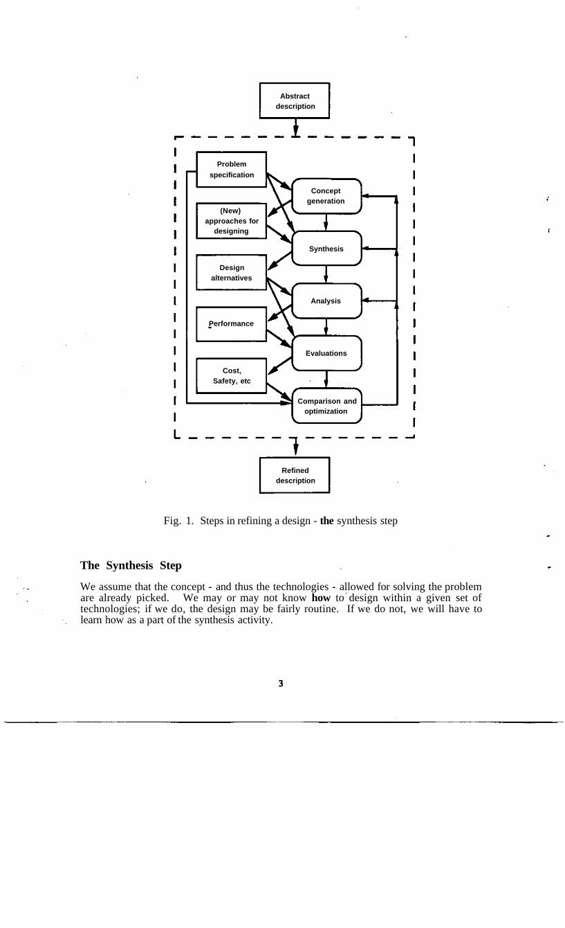
Fig. 1. Steps in refining a design - the synthesis step
The Synthesis Step
We assume that the concept - and thus the technologies - allowed for solving the problemare already picked. We may or may not know how to design within a given set oftechnologies; if we do, the design may be fairly routine. If we do not, we will have tolearn how as a part of the synthesis activity.
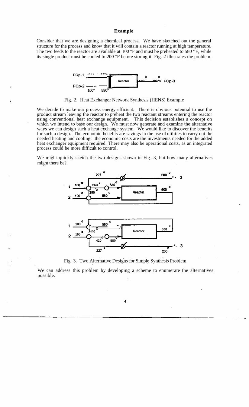
Example
Consider that we are designing a chemical process. We have sketched out the generalstructure for the process and know that it will contain a reactor running at high temperature.The two feeds to the reactor are available at 100 °F and must be preheated to 580 °F, whileits single product must be cooled to 200 °F before storing it Fig. 2 illustrates the problem.
FCp-1 1 0 0 ° 5 8 0 °
FCp-2100° 580°
I Reactoro o
600 200*> FCp-3
Fig. 2. Heat Exchanger Network Synthesis (HENS) Example
We decide to make our process energy efficient. There is obvious potential to use theproduct stream leaving the reactor to preheat the two reactant streams entering the reactorusing conventional heat exchange equipment. This decision establishes a concept onwhich we intend to base our design. We must now generate and examine the alternativeways we can design such a heat exchange system. We would like to discover the benefitsfor such a design. The economic benefits are savings in the use of utilities to carry out theneeded heating and cooling; the economic costs are the investments needed for the addedheat exchanger equipment required. There may also be operational costs, as an integratedprocess could be more difficult to control.
We might quickly sketch the two designs shown in Fig. 3, but how many alternativesmight there be?
* • 3
100
100
I o
J o ^J440
I 420 580
Reactor
0600
227-*- 3
200
Fig. 3. Two Alternative Designs for Simple Synthesis Problem
We can address this problem by developing a scheme to enumerate the alternativespossible.

An enumeration scheme
The streams involved are three cold streams (Cl, C2 and cooling water) and three hotstreams (hot water, HI, and steam). The allowable matches between these streams are asfollows.
ClC2
cooling water
hot water HI steam
Thus there are three kinds of streams: (1) Cl, C2 and HI which meet up to three otherstreams; (2) hot water and steam which meet up to two other streams and (3) cooling waterwhich meets with up to one other stream.
Fig. 4 is a sketch of all the ways that one stream could meet with three other streamsexactly one time.
rCh rCh
1 6 6
Fig. 4. All Alternative Ways for One Stream to Meet Three Others Once Each
The stream could split into three parts and meet the other three in parallel. There is onlyone configuration for this option.
It could split into two parts for meeting two of the streams. The third would be metwithout splitting and could be either the first or last stream to exchange with our stream.Therefore, any one of the three streams could be the one met without splitting (3alternatives) and the splitting could come first or last (2 alternatives) giving 2 x 3 = 6possible configurations, as indicated in the middle option above.
Finally our stream could meet the other three streams in series, but there are 3! = 6 possibleorderings for it to meet the other streams: 123,132,213,231,312 or 321.
We therefore find that, if it meets all three of the other streams, there are 13 alternativespatterns possible.
Similarly for a stream which can exchange with two other streams, there are 3 alternativeconfigurations, one where they meet in parallel and two where they meet in series.
With just these possibilities, we discover we can already enumerate 133 x 3 2 = 19773alternatives. There are many, many more than these possible if we allow any two streamsto exchange heat more than one time or not al all. Of course almost all of these alternativeswould not make sense for any number of reasons. The above enumeration has examinedonly the structural possibilities.
We can see that even when the technology is apparent - i.e., we shall use simple heatexchangers - the synthesis problem can be formidable. A designer cannot look only at oneor two alternatives as she or he will almost certainly miss the better solutions.
Really hard synthesis problems
For many types of design problems, it is relatively easy to generate alternatives. For theheat exchanger network synthesis problem described above, the real problem is toguarantee that no alternative is overlooked. For distillation-based separation problemswhere the species are relatively well behaved, one can also quickly develop alternatives.For example, to separate a mixture four components, ABCD, into four relatively puresingle component products, one alternative is to split A from BCD, then split BC from Dand finally split B from C. Four other simple schemes exist, along with an abundance ofmany others if parallel and/or multieffect columns are permitted. It is interesting to notethat these two problems are the ones most often considered in the process synthesisliterature.
There are problems where generation of even a single feasible alternative, much less allpossible alternatives, is extremely difficult, given today's understanding of the problem.One such problem is the synthesis of a separation scheme for liquid mixtures where thespecies display complex homogeneous and heterogeneous azeotropic behavior. A verycomplex problem in this class is to separate a mixture of water, methanol, acetone and n-pentane, a problem which wje offered as a challenge problem to a recent conference onseparation - no one solved it during the time available. Five of the six binary pairs in thismixture display azeotropic behavior, the exception being the methanol/water pair. If oneproposes to distill this mixture, then what are the possible products that can be produced?Of these products, which are actually interesting in that they have a high probability ofappearing in a final design alternative? Distilling an azeotropic mixture leads to productswhich are only partially separated. It will always be necessary to recycle partially separatedmixtures produced later in a flowsheet back to an earlier separator. Using a problemdecomposition that develops a tree of only a few quite distinct alternatives, Wahnschafft etal [1991] propose a methodology that requires a combination of both qualitative reasoning(to keep the search space small enough) and quantitative reasoning (many columnsimulations are needed to discover product distributions).
Two other problems we might currently classify as extremely hard are the synthesis ofreactor networks and separation systems using reactive distillation.
General Approaches to Synthesis
We can look at the general approaches possible to carry out the synthesis task. In severalof these cases, we shall also give an example which illustrates the approach.
Total enumeration - generate and test
Enumerate all possible structures. Then among these structures rule out those which failfeasibility checks or which are poor at meeting one of the evaluation criteria such as beingtoo expensive to purchase or operate, unsafe, expensive to manufacture or too inflexible.This approach is usually not possible as the number of alternatives is too large.

One has to take care that all alternatives are discovered, often a formidable task. Also thegeneration algorithm may develop the same solution many, many times, which can wasteconsiderable time on what is already a very large problem.
Evolutionary search - test and generate
Generate a good first solution (use heuristics), then make small changes until noimprovement is possible. This approach is frequently used by designers, but it should beevident that the method will stop at "local" optima, what are called a "topology traps" in theheat exchanger network synthesis literature. It will stop when no adjacent new solution isan improvement over the last. There could be a good solution two or three steps away, butit will not be found.
There are two alternative approaches to the making of small changes. A first approach is tohave a list of possible changes and make them one at a time, testing each to see if it leads toan improvement. An alternate approach is to examine the solution and from it decide wherethe next changes ought to be made. For example, there could be a part of the design that israther expensive, unsafe and/or difficult to manufacture. Changes in this part of the designwould be the first to be proposed. The latter is a variant of the former where one is able torank order the changes by some heuristic criteria.
Means/ends
Mean/ends is an approach which can be used to add structure to a partially completeddesign. For this approach one has to define a state vector of attributes for the design.These states are initialized to reflect the start of the design. The designer must also identifythe final goal state at the start. A difference metric measures how far the current state isfrom the final goal state. The design system must have operators which can reduce theobserved differences. Observing a difference in the current state and the goal state, thesystem picks among the operators to change the current state to a new state which is closer- it is hoped - to the goal state. This approach is basically useful to find a feasible solution,but it offers little to one in finding the better solutions unless it is combined with otherideas.
Example
In a heat exchanger problem, start with all the process streams at their input temperatures.These temperatures will be the current state of the design. The goal state is the set of targetoutput temperatures for all the process streams. The difference metric will be the differencein the current and goal temperatures for each of the streams. Propose a heat exchanger{operator to remove the differences between the current state and the goal state) be placedbetween a hot stream which is to be cooled and one of the cold streams which is still colderthan it and is not at its target either. Exchange all the heat which can be before (1) one ofthe streams reaches its target temperature or (2) the stream temperatures approach eachother and preclude further exchange. This approach formed the basis of an early heatexchanger network synthesis algorithm by Ponton and Donaldson [1973].
Embedded optimization
Set up a superstructure in which all alternatives of interest are embedded and useoptimization to find the best substructure. This approach was proposed very early in thesynthesis literature [Ichikawa et al, 1969]. In the earliest of these approaches, every unit ina superstructure received input from the output of every other unit. Split factors, aij, were

used to determine what fraction of output from unit i would be directed to the input of unitj; these split factors are continuous variables. The problem with this formulation is that asolution tends to have a little bit of every unit in it as there was no way to add a cost for theexistence of a unit. More recent approaches, especially the work by Grossmann and hisstudents and coworkers, add binary variables to the formulation which have the value oneif a unit is present and zero otherwise. A cost related to the existence of a unit, no matterhow large it is, can then be added to the objective function. The solution will usually havemany fewer units in it as a result Also one can write constraints which will exclude certaincombinations of units; for example, if unit A is present, then unit B cannot be.
Example
Part faf in Fig. 5 represents a superstructure for one stream meeting three other streams toexchange heat. Part V shows a substructure in which it meets streams 1 and 2 in paralleland then meets stream 3. fc* shows the substructure in which it exchanges in series withstreams 2, 1 and 3.
i I•O-i -
- t 2
(a) (b) (c)
Fig. 5. A Superstructure Representation for Heat Exchanger Networks
Branch and bound searching
Some problems can be "constructed" and evaluated one part at a time. At each step therewill be many next parts to add. The next more complete partial solutions each branch fromthe current partial solution. These partial evaluations may offer a lower bound on the costinvolved for including them within the solution. One can then select the branch with thelowest partial cost and add another part to that solution. If one can get a complete solutionwith a cost below that of the lower bounds for all the other branches in the search space,then it is guaranteed to be the best solution.
Constraint directed search
Many of the searches described already or following typically involve a form of constraintdirected search. They create part of the solution and for it establish a number of constraintson the rest of the design. The generation algorithm is designed to avoid the generation ofdesigns which will violate these constraints.
Example
In the synthesis of heat exchanger networks, one might wish to generate solutions in anevolutionary fashion, adding one exchanger at a time. There could be a constraint that two
streams can meet at most two times in a solution. Once a solution contains two matchesbetween a pair of streams, the system will not generate any further solutions with those twostreams matching yet one more time.
Heuristic searching
Rather than developing a rigorous cost function, one might simply use rules of thumbbased on experience or intuition to decide which part to add next. This approach is rapidbut of course has no guarantee of picking the best solution.
Heuristic pruning
A branch and bound type of search can also be pruned using heuristics. Some branches areeliminated by using heuristics which suggest they cannot lead to a good solution. The sizeof the search space can be dramatically reduced with such an approach.
Hierarchical decompositions/abstraction
In some problems - indeed, in most - one might use a more abstract form for the problemand make decisions using that less detailed view. Decisions made will greatly reducenumber of decisions to be made in a more detailed form for problem. When one first setstargets which become constraints for the design for heat exchanger networks, one is usingthis type of approach.
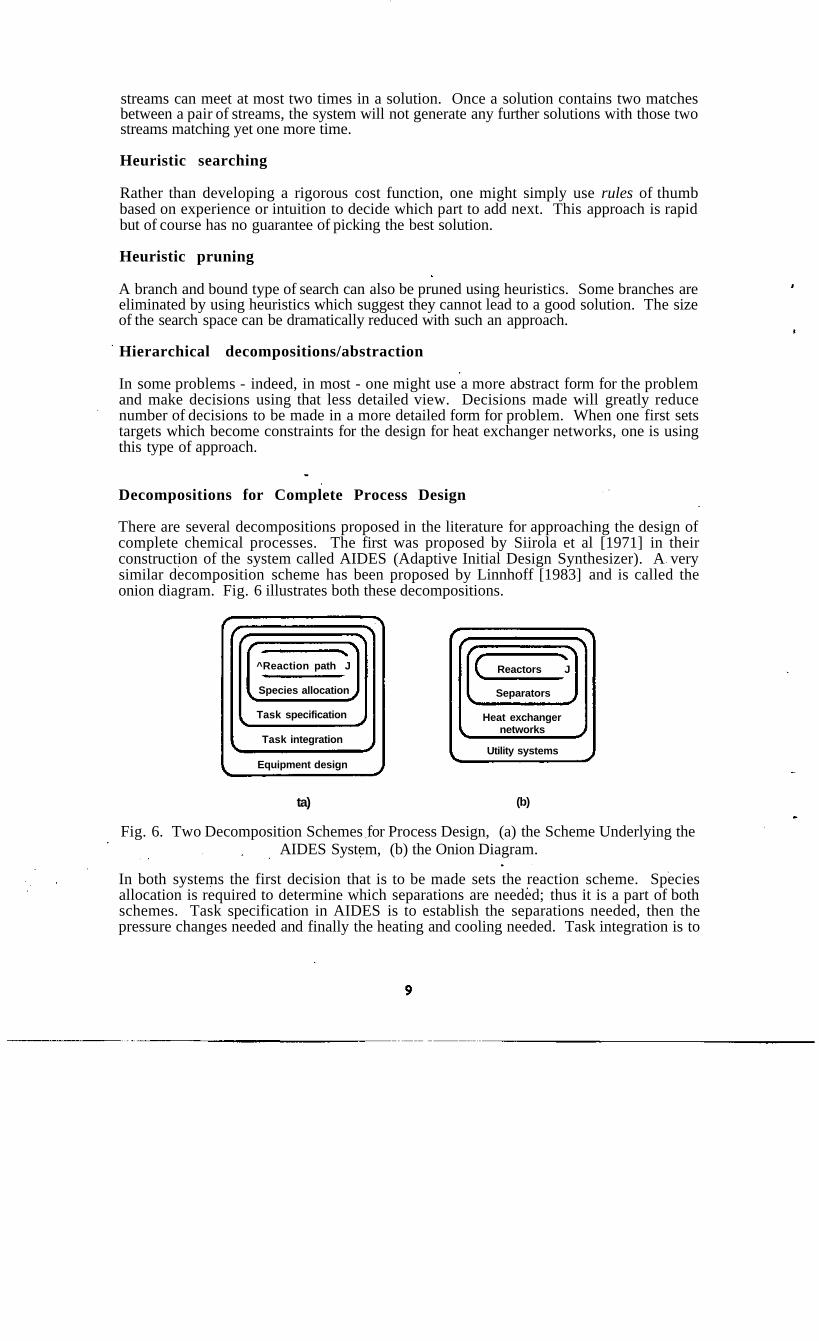
Decompositions for Complete Process Design
There are several decompositions proposed in the literature for approaching the design ofcomplete chemical processes. The first was proposed by Siirola et al [1971] in theirconstruction of the system called AIDES (Adaptive Initial Design Synthesizer). A verysimilar decomposition scheme has been proposed by Linnhoff [1983] and is called theonion diagram. Fig. 6 illustrates both these decompositions.
^Reaction path J
Species allocation
Task specification
Task integration
Equipment design
Reactors J
Separators
Heat exchangernetworks
Utility systems
ta) (b)
Fig. 6. Two Decomposition Schemes for Process Design, (a) the Scheme Underlying theAIDES System, (b) the Onion Diagram.
In both systems the first decision that is to be made sets the reaction scheme. Speciesallocation is required to determine which separations are needed; thus it is a part of bothschemes. Task specification in AIDES is to establish the separations needed, then thepressure changes needed and finally the heating and cooling needed. Task integration is to
establish the heat exchange network structure. Linnhoff adds the need to establish thedesign of the utility system.
Mahalec and Motard [1977a,b], in the design of the Baltazar system, propose adecomposition that treats streams one at a time. Reaction, separation, heating and pressurechanging tasks arc added as needed to convert input streams into the desired outputstreams. The final step is to integrate the heating and cooling tasks.
Douglas [1988] presents a decomposition scheme based on the decisions to be made. Heargues that fewer than 1% of die ideas proposed for new designs will ever be built, and,therefore, his goal is to eliminate uneconomic designs as with as little work as possible.His approach is to keep alternatives "alive" until they can be shown to be uneconomic orless economic than another option. Implicit in his approach is that designers should makeoptimistic decisions when there is insufficient information available because it is expectedthat, even when being optimistic, the design will readily be shown to fail. Also implicit isthat designers should always be trying to discover why their designs will fail, not why theywill succeed. Anyone who has had a design fail after being constructed will sympathizewith this attitude.
His scheme first decides if the process should be a batch or continuous one. For acontinuous process, he establishes what are the feeds entering and the products, biproductsand waste streams leaving based only on selectivity information for the reactions involved.An economic potential (the value of the products less the costs for the feeds to the process)is readily established by assuming that all of the reactants entering will be recycled untilthey react, except those that ftiight be lost when using a gas purge stream. The potentialgross profit based on the value of the products less the cost of the reactants is plottedversus the size or composition of the purge stream(s). His next level of decisions requirethat one know the conversions that can be attained in each reaction step, allowing him toestablish the recycles flows in the process. Given the recycles flows, one can size andestimate the cost for the reactor (vessel and catalyst) and the recycle compressors. Nextone designs the separation system and finally the heat exchange network.
In all these decompositions, heat integration is left as a last step. At the time it is to occur,all pressures, temperatures and stream flowrates are established. Thus the heat integrationis for the "classic" heat integration problem, a problem in which each of the processstreams to be heated or cooled is characterized by its flow rate, its inlet and outlettemperatures and its heat capacity versus temperature.
As indicated in the introduction and as is well known, heat integration does affect the earlierdecisions. Thus, if one uses these decompositions, there is a need for a step to follow theiruse that allows for the earlier decisions to be altered based on the results developed by laterones. We save such a discussion for later.
We shall now look at the key results that are available for the "classic" heat exchangernetwork synthesis problem.
Fundamental Insights for the "Classic" Heat Exchanger Network SynthesisProblem .
In this problem, we have developed a design and set all the flows, temperatures andpressures throughout it. From this design we extract a set of hot streams to be cooled and aset of cold streams to be heated. For each one is given its flow rate, its inlet temperature, itsoutlet temperature and its heat capacity as a function of its temperature. We may also be
10

given a set of available hot and cold utilities. The problem is to determine the heatexchanger network which minimizes the total annualized cost for the network - i.e., theannual cost of the utilities needed plus the annualized cost for the heat exchangerequipment
Characterizing the heat capacity of a stream versus its temperature sometimes requires oneto make decisions that may not yet have been made for the flowsheet. The simple structureshown in Fig. 2 of a reactor is a case in point. Suppose the streams entering are at ambientconditions and one is a liquid Further suppose the reactor is operating at high temperatureand pressure in the vapor phase. One must decide on the temperature at which to vaporizethe liquid stream. To add the heat of vaporization at the lowest temperature suggestsvaporizing first and then adding pressure. However, that decision would force one to use acompressor rather than a pump for adding the pressure, a decision one is unlikely to makebecause compressors are so expensive to purchase and operate. One is most likely to pumpthe liquid to the reactor pressure and then add heat, which, of course, is the worst decisionone could make from the point of view of heat integration as the heat of vaporization willnow have to be added at the highest temperature possible.
Any of the methodologies mentioned above could be used to develop a network for thisproblem. Total enumeration, for example, could be implemented by explicitly creatingevery possible network topology. Each can then be evaluated for feasibility againstthermodynamic constraints. For each one that passes, one could carry out an optimizationto establish its best economic value. Clearly such a search is too large to be carried out inthis manner.
Representations and insights for heat flows in a process
To present this discussion we shall illustrate the ideas with a problem 4SP1 (4 streamproblem number 1), a test problem proposed years ago by Rudd to test out his and futurealgorithms for heat exchanger network synthesis.
Example
Table 1 presents the stream data for problem 4SP1. The problem has two cold streams andtwo hot streams. Shown for each are its flowrate times its heat capacity and its inlet andoutlet temperatures.
Table 1. Stream data for 4SP1.
stream FCp(kW/°C) Tin(°C) Tout(°C)
Cl 7.62 60 160C2 6.08 116 260
HI 8.79 160 93H2 10.55 249 138
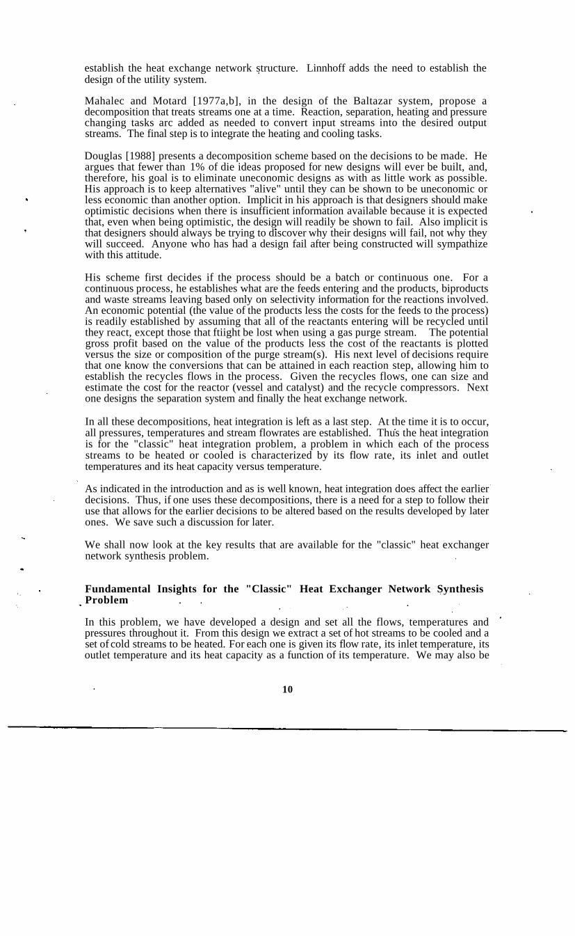
Hohmann/Lockhart composite curves
Hohmann [1971], working with Lockhart, published the classic PhD thesis on networkdesign. In one of his main results, he extended a representation by Whistler [1948] whichdisplayed the temperature of each stream to be integrated versus the enthalpy content of that
11
T.K
200
100
2000 1000
Cascaded Heat, kW
Fig. 7. Hohmann/Lockhart Composite Curves for Determining Minimum Utility Use
Table 2. "Extended" Problem Table for 4SP1 for A T ^ fixed at 10 K
CompositeHot Streams
Avail CascadedHeat
—
833.5
105.5
425.5
105.5
290.1
...
Heat
0.0
833.5
939.0
1364.5
1470.0
1760.1
1760.1
Temperatures
Hot
(270)
H?
H1
• •
- 249
(170)
160
- 138
(126)
93
(70)
7
6
5
4
3
2
1
Cold
260
(239)
160
(150)
(128)
116
83
60
CompositeCold Streams i
Req'd CascadedHeat
C2
C1• •
• •
wm
127.7
480.3
137.0
301.4
164.4
251.5
175.3
Heat |
0.0 I
127.7
608.0
745.0
1046.4
121O.8f
1462.3
1637.6
Grand CompositeHot and Cold Streams
NetHeat
-127.7
353.1
-31.5
124.1
-58.9
E 38.6
| -175.3
Casc'd AdjCascHeat
0.0
-127.7
225.4
193.9
318.0
259.1
297.7
122.4
Heat
127.7
0.0
353.1
321.6
445.7
386.8
425.4
250.1
12
stream. Hohmann merged all the hot streams into a single hot stream and all the cold into asingle cold stream on such a plot, producing what is now call the composite curve diagram.Plotting one of these on a transparency allows one to move one relative to the other toestablish the integration possible versus the minimum approach temperature selected. Fig.7 shows this plot with the curves moved to within 10 K of each other.
Problem table
The problem table representation of Linnhoff and Flower [1978] requires one to assume afixed minimum temperature difference for the problem. The problem is then partitionedinto temperature intervals whose demarcations are the inlet and exit temperatures for all thestreams. Table 2 illustrates. A different set of streams exists in each interval.
The Hohmann/Lockhart composite curves shown above in Fig. 7 are a plot of the cascadedhot and cascaded cold columns in this table
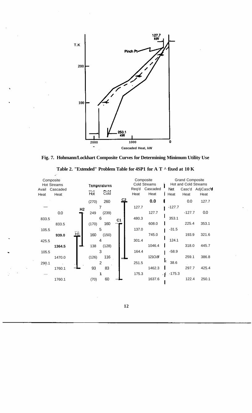
Heat path diagram
Fig. 8 is a network illustrating these heats flows. It has been called a heat path diagram[Westerberg, 1983] which shows only legal paths for heat flow - i.e., from hotter sourcesto colder sinks. The figure shows a linear programming model for this problem thatcorresponds to writing the heat balances around each of these nodes. The objective function
cold streams
MIN Q01 + R02s.t.
Q01 »127.7R02 + 833.5 * Q22 + R23Q22 = 480.3
Q33 = 137.0R34 + 425.5 « Q44 + R45044*301.4R45 + 105.5-Q55 + R56Q55 = 164.4R56 + 290.1 = Q66 + Q67 + Q68Q66 = 251.5067 = 175.3
ailQij, Rkl^O
Fig. 8. Heat Path Diagram and Its Associated Linear Programming Model for ComputingMinimum Utilities Required
13

is to minimize the amount of heat required from the hot utility.
One can extend these ideas to restricted problems where, for example, we might not permitheat to transfer from hot stream H2 to cold stream Ci. Fig. 9 illustrates.
Fig. 9. "Heat path diagram" for Restricted Heat Flow Problem for 4SP1
Grand composite curve
The third column from the right in the problem table, Table 2, is the result of computing thenet heat produced in an interval. It is the difference in the heat produced and the heatrequired. One can readily show that the streams in an interval can always exchange thelesser of the heat available and the heat needed in a countercurrent heat exchange withoutviolating the minimum temperature driving force. A plot of this last column produces whatis termed the grand composite curve [Itoh et al, 1982; Linnhoff 1983] - see Fig. 10.
The grand composite curve is a breakthrough in representation as it characterizes the netheat flow characteristics of a process versus temperature. Where the curve has a positiveslope, the process is acting as a net heat sink over that temperature range; where is has anegative slope, it is acting as a net heat source. The portions on this diagram labeled asnoses correspond to streams which are heat sources that are hotter than streams acting asheat sinks; the streams involved within these noses have the same amount of heat involvedand can always be heat integrated with each other. What is left over after cancelling the
14

noses is shown as darkened curves which are the coldest temperatures at which heat can beput into the process and the hottest temperatures at which it can be removed.
T.K
210/200
110/100
This heat can beadded using hot
utilities
This heatcan be
removedusing cold
utilities
These "noses-can be self-integrated
250.1kW
1000
Net heat, kW
Fig. 10. Use of Grand Composite Curve to Find Temperatures at Which Utilities AreReally Needed for a Process
The pinch point
The point in the grand composite curve where the curve touches zero net heat is a pinchpoint for the process. Above this point the process acts high temperature heat sink whilebelow it the process acts as a low temperature heat source. No heat can pass across thepinch point if the process is to consume minimum utilities.
Minimum number of exchanges
Based strictly on topological arguments, it will generally take a minimum of N-l exchangesto integrate N total hot and cold process and utility streams where the total heat availableexactly matches that needed.
Area estimates
The Hohmann/Lockhart composite curves offer a way to estimate the area needed by anetwork. Assume that one integrates the streams so the temperature profile in eachexchanger exactly follows these composite curves. We note that the incrementalcontribution to the area for two streams, i and j, exchanging heat is given by:
15

UyAT hi hj AT
Then an area estimate for all the streams in the process being integrated can be estimated as[TownsendandLinnhoff, 1984]:
Area^ _AT(T)
which is summed over all hot and cold streams. Each term contributes part of the areawithin any exchanger in which the stream exists. AT(T) is approximated as the temperaturedifference between the composite curves as a function of T.
Capital cost estimation
One can estimate the investment cost for a network as that required to purchase thatestimated area in N-l exchangers. This estimate is done without creating a network tocarry out the integration.
Optimal minimum temperature driving force
One can shift the Hohmann/Lockhart Composite Curves relative to each other. For eachposition, the plot indicates the utilities required as well as the minimum temperature drivingforce. Using these curves one can estimate the capital investment as just described. If thecurves are too close, the investment will tend to infinity, while, as they move apart, one hasto purchase more utilities. A simple plot of the annualized cost of utilities and equipmentversus the minimum driving force can be used to establish the driving force which willminimize the estimated annualized cost for the equipment and the utilities.
Refinements of these results
Gundersen and Naess [1988] and Gundersen {1991] review several refinements to theseinsights which have appeared in the literature over the past few years. Work has been doneto allow multi-pass exchangers, to allow much better area estimates, etc.
Design methodologies for the classic problem
There are two basic approaches to the synthesis of heat exchanger networks: one based ontarget setting using the above insights and one based on superstructure optimization, aswell as methods which are hybrids of these two approaches.
Interestingly the first paper usually quoted for heat exchanger network synthesis [Hwa,1965] used a math programming model. Each stream was partitioned into a number ofequal packets of heat. The math programming model was to assign each hot packet to acold packet so as to minimize annualized cost. If the cost is strictly that of purchasingutilities, this model predicts the minimum utility use. It suffers from the fact that themarginal cost of area for each packet is a relatively strong function of how many packetswill end up being in each of the exchangers. Only a few packets will give a small
16

exchanger with a large marginal cost for area, while large collections of packets thatbecome a single large exchanger will have a quite small marginal cost.
Once the idea of predicting targets became well understood, the methodology for designfollowed roughly the following sequence of steps.
1) Develop the composite curves.
2) Predict the best value for the approach temperature using the approach describedabove.
3) Partition the process at the pinch point into two independent design problems.
4) Estimate the fewest exchangers needed above the pinch and below the pinch
5) Design a heat exchanger network for the process above the pinch point. Do notallow any cold utility to be used.
6) Design a network for the process below the pinch point. Do not allow any hotutility to be used.
7) If there are more than the minimum number of exchangers involved in these twoindependent designs, look for heat cycles in the design. Attempt to remove these.
8) Treat the two problems as one and attempt to remove cycles. To do so will requirethat the use of utilities increase and heat will be passed across the pinch point.
The invention of the network in step 5 has been done by hand using insights - the pinchdesign method. It has. also been done by setting up superstructures as described above andoptimizing these to find the best of them. All the insights were first used to reduce theproblem size.
Experience showed that the none of these methods guaranteed finding the best networks.Of late however, Gundersen [1991] reports that there are now superstructure basedmethods that do find the better solutions [Yee and Grossmann, 1990]. Since theseproblems are often nonconvex, finding such solutions is still not guaranteed.
If we were to summarize the above, we might state that the classical heat exchangernetwork synthesis problem is in pretty good shape. We shall now look beyond it.
Coupling Heat Integrations with Earlier Design Decisions
Heat integration has to influence earlier design decisions as it effectively reduces the cost ofutilities for the process. We now look at problems where the flows and temperatures arenot fixed in deciding the design.
The heat cascade diagram to aid proper placement
The first such process that we worked on in our research was to design multieffectevaporation systems [Hillenbrand, 1984; Hillenbrand and Westerberg, 1988a,b]. Thedesign problems is to select the number of effects, the temperature levels for them as wellas the heat integration. This work also included integrating the effects with a backgroundprocess characterized by its grand composite curve.
17
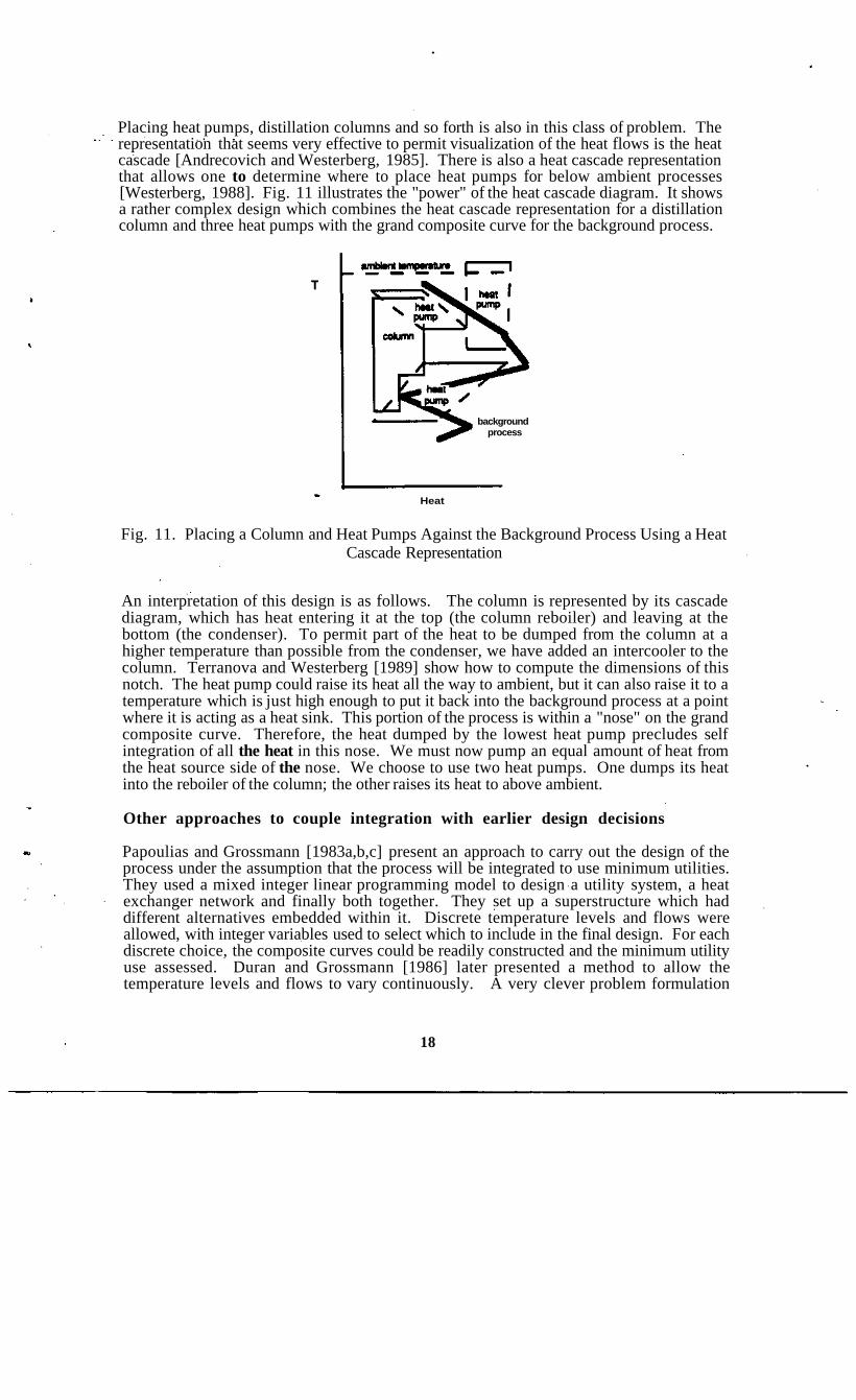
Placing heat pumps, distillation columns and so forth is also in this class of problem. Therepresentation that seems very effective to permit visualization of the heat flows is the heatcascade [Andrecovich and Westerberg, 1985]. There is also a heat cascade representationthat allows one to determine where to place heat pumps for below ambient processes[Westerberg, 1988]. Fig. 11 illustrates the "power" of the heat cascade diagram. It showsa rather complex design which combines the heat cascade representation for a distillationcolumn and three heat pumps with the grand composite curve for the background process.
backgroundprocess
Heat
Fig. 11. Placing a Column and Heat Pumps Against the Background Process Using a HeatCascade Representation
An interpretation of this design is as follows. The column is represented by its cascadediagram, which has heat entering it at the top (the column reboiler) and leaving at thebottom (the condenser). To permit part of the heat to be dumped from the column at ahigher temperature than possible from the condenser, we have added an intercooler to thecolumn. Terranova and Westerberg [1989] show how to compute the dimensions of thisnotch. The heat pump could raise its heat all the way to ambient, but it can also raise it to atemperature which is just high enough to put it back into the background process at a pointwhere it is acting as a heat sink. This portion of the process is within a "nose" on the grandcomposite curve. Therefore, the heat dumped by the lowest heat pump precludes selfintegration of all the heat in this nose. We must now pump an equal amount of heat fromthe heat source side of the nose. We choose to use two heat pumps. One dumps its heatinto the reboiler of the column; the other raises its heat to above ambient.
Other approaches to couple integration with earlier design decisions
Papoulias and Grossmann [1983a,b,c] present an approach to carry out the design of theprocess under the assumption that the process will be integrated to use minimum utilities.They used a mixed integer linear programming model to design a utility system, a heatexchanger network and finally both together. They set up a superstructure which haddifferent alternatives embedded within it. Discrete temperature levels and flows wereallowed, with integer variables used to select which to include in the final design. For eachdiscrete choice, the composite curves could be readily constructed and the minimum utilityuse assessed. Duran and Grossmann [1986] later presented a method to allow thetemperature levels and flows to vary continuously. A very clever problem formulation
18

permitted the composite curves to shift continuously and the pinch point location to moveas needed.
Lien et al [1987] suggest using approximate T-Q diagrams to give guidance as to thetemperature levels at which to operate distillation columns so they will heat integrate.Hows were characterized as large, medium and small in constructing these diagrams. Itbecame rather easy to see many of the potential heat integrations without carrying out ananalysis. This paper discusses the potential of using expert systems for design.
Mizsey and Fonyo [1990] presented a three step procedure for designing processes andillustrated it with three different process designs. They use Douglas1 hierarchicaldecomposition to discover a number of good process alternatives. The user then interactswith these proposed designs to allow biro/her to apply knowledge the system does not havein selecting among them and to add in alternatives which the system is not programmed tocreate.
As pointed out before, integration reduces the apparent cost of energy for a process.Mizsey and Fonyo noted that reactor conversions for the optimal integrated processes theystudied were always less than for the optimal unintegrated processes. Selectivity istypically improved at lower conversions, so more of the raw material is converted toproduct at lower conversions. Lower conversions, however, require more recycling ofmaterials and thus more energy use. Cheaper apparent energy favors more energy use.They developed a bounding procedure based on this observation that allows them toeliminate designs.
Rigorous simulation is used to determine the actual costs for the different alternatives withthe alternative having the highest real profits being selected. From the insights givenearlier, one can readily understand the basis of their approach.
Manousiouthakis and Bagajewicz [1990] presented an interesting representation that allowsone to set up complex superstructures for entire processes (where temperatures and flowsare allowed to vary) in a rather straight forward manner. Parts in the superstructure cansimply be mass and/or heat exchanger networks that use minimum utilities - i.e., thenetwork can be represented only by its performance and not by the structure of theequipment
It would appear these studies have moved energy integration to the outer loop of decisionmaking. It can be pushed out one step further, to the level of generating the original designconcept itself by examining the ideas in Lien et al [1987] a bit more. In this paper theyexamined the manufacture of ethylbenzene using ethylene and benzene feed. The literaturehas two processes, a vapor phase one run at quite high temperatures and having a quitehigh benzene recycle and a liquid phase process at low temperatures and a moderatebenzene recycle. It would seem the vapor phase process could not win against the liquidphase process, yet both are commercialized. An interesting guess is that the reaction isexothermic so that running it at high temperatures provides heat for running the distillationcolumns, whereas the heat of reaction from the liquid process may not be hot enough. Ifso one can explain why the vapor phase reaction is economically possible. The reaction isin fact exothermic and provides considerable heat A design concept which this reasoningsuggests is as follows. If the heat is large enough, why not design a combined processwith both the liquid phase reaction and the vapor phase reaction present. The latter canprovide heat to run itself and extra heat to run the liquid phase reaction.
19

References
Andrecovich, M.J., and A.W. Westerberg, "A Simple Synthesis Methcxi Based on Utilitybounding for Heat Integrated Distillation Sequences," AIChE J, Vol. 31, No. 3, 363-375(1985).
Douglas, J.M., Conceptual Design of Processes. McGraw-Hill, Inc., New York (1988).
Duran, M.A., and I.E. Grossmann, "Simultaneous Optimization and Heat Integration ofChemical Processes, "AIChE J, Vol. 32,123-138 (1986).
Gundersen, T, "Achievements and Future Challenges in Industrial Design Applications ofProcess System Engineering," Proc. 4th Intern! Symp. on Process Systems Engineering,Montibello, Quebec, Canada, August 5-9 (1991).
Gundersen, T., and L. Naess, "The Synthesis of Cost Optimal Heat Exchanger Networks.An Industrial Review of the State of the Art," Computers chem. Engng, Vol. 12, No. 6,503-530 (1988).
Hillenbrand, J.B., Studies in the Synthesis of Energy-efficient Evaporation Systems. PhDThesis, Carnegie Mellon Univ., Pittsburgh, PA (1984).
Hillenbrand, J.B., and A.W. Westerberg, "The Synthesis of Multiple-effect EvaporatorSystems Using Minimum Utility Insights -1 . A Cascaded Heat Representation. -EL LiquidFlowpattern Selection," Computers chem Engng, Vol. 12, No. 7, 611-624, 625-636(1988a,b).
Hohmann, E.C., Optimum Networks for Heat Exchange. PhD Thesis, Univ. So. Calif.(1971).
Hwa, C.S., "Mathematical Formulation and Optimization of Heat Exchange NetworksUsing Separable Programming," AIChE-Intern. Chem. Eng. Symp. Series, No. 4, 101(1965).
Ichikawa, A., N. Nashida, and T. Umeda, "An Approach to the Optimal SynthesisProblem," 34th Annual Mtg, Soc. Chem. Engineers, Japan (1969).
Itoh, J., K. Shiroko, and T. Umeda, "Extensive Applications of the T-Q Diagram to HeatIntegrated System Synthesis," Proc. Internl Symp. Proc. Systems Engng (PSE-82),Kyoto, Japan, 92-99, August 23-27 (1982).
Lien, K., G. Suzuki, and A.W. Westerberg, "The Role of Expert Systems Technology inDesign," Chcm, Eng. Sci., Vol. 42, No. 5,1049-1071 (1987).
Linnhoff, B.f "New Concepts in Thermodynamics for Better Chemical Process Design,"Chem. Eng. Res. Design, Vol. 61, 207-223, July (1983).
Linnhoff, B., and J.R. Flower, "Synthesis of Heat Exchanger Networks, Part I., Systematic Generation of Energy Optimal Networks," AICHE J., Vol. 24,633 (1978).
Mahalec, V., and R.L. Motard, "Procedures for the Initial Design of Chemical ProcessSystems," Computers chem Engng, Vol. 1, 57 (1977a).
20
Mahalec, V., and R.L. Motard, "Evolutionary Search for Optimal Limiting ProcessFlowsheet," Computers chem Engng, Vol. 1,149 (1977b).
Manousiouthakis, V., M. Bagajewicz, "Synthesis of Distillation Networks FeaturingMinimum Utility Consumption," paper 215h, AIChE Annual Mtg, Chicago, EL, Nov. 11-16 (1990).
Mizsey, P., and Z. Fonyo, "Toward a More Realistic Overall Process Synthesis - theCombined approach," Computers chem. Engng., Vol. 14, No. 11, 1213-1236 (1990).
Papoulias, S.A., and I.E. Grossmann, "A Structural Optimization Approach to ProcessSynthesis - I. Utility Systems. -II Heat Recovery Networks. -III. Total ProcessingSystems" Computers chem. Engng., Vol. 7, 695-706, 707-721, 723-734 (1983a,b,c).
Ponton, J.M., and R.A.B. Donaldson, "A Fast Method for the Synthesis of Optimal HeatExchanger Networks by Tree Search Algorithms," AIChE J, Vol. 19,1182 (1973).
Siirola, J.J., G. J. Powers, and D.F. Rudd, "Synthesis of System Designs, III: Toward aProcess Concept Generator," AIChE J, Vol. 17, 677 (1971).
Terranova, B.E., and A.W. Westerberg, "Temperature-Heat Diagram for ComplexColumns. I. Intercooled/Interheated Distillation Columns," I&EC Res., Vol. 28, 1374-1379 (1989).
Townsend, D.W., and B. -Linnhoff, "Surface Area Targets for Heat ExchangerNetworks," IChemE Annual Research Mtg, Bath (1984).
Wahnschafft, O.M., P. Blania, J.P. LeRudulier, M. Thomas and A.W. Westerberg,"SPLIT: II. Automated Synthesis of Hybrid Liquid Separation Systems," submitted forpublication (1991).
Westerberg, A.W., "The Heat Path Diagram for Energy Management," paper 22f, AIChEDiamond Jubilee Mtg, Washington, DC, Oct-Nov (1983).
Westerberg, A.W., "Synthesis of Heat Pumps," in Biegler, L.T., I.E. Grossmann andA.W. Westerberg, Shortcourse Notes for Computer Methods for Process Design andOptimization, Carnegie Mellon Univ. (1988).
Westerberg, A.W., "Synthesis in Engineering Design," Computers chem Engng, Vol. 13,No. 4/5, 365-376 (1989).
Whistler, A.M., "Heat Exchangers as Money Makers," Petroleum Refiner, Vol. 27, No. 1,83-86 (1948).
Yee, T.F., and I.E. Grossmann, "Simultaneous Optimization Models for Heat Integration -II. Heat Exchanger Network Synthesis," Computers chem Engng, Vol. 14, No. 10, 1165-1184(1990).
21


![IS 788 8.11 IS 788 [Process] Change Management Lecture: Process Redesign Methodologies.](https://static.fdocuments.us/doc/165x107/56649d375503460f94a0f429/is-788-811-is-788-process-change-management-lecture-process-redesign.jpg)