An Overview of Peak-to-Average Power Ratio Reduction...
11
JOURNAL OF COMMUNICATIONS AND NETWORKS, VOL. 11, NO. 3, JUNE 2009 229 An Overview of Peak-to-Average Power Ratio Reduction Schemes for OFDM Signals Dae-Woon Lim, Seok-Joong Heo, and Jong-Seon No (Invited Paper) Abstract: Orthogonal frequency division multiplexing (OFDM) has been adopted as a standard for various high data rate wire- less communication systems due to the spectral bandwidth effi- ciency, robustness to frequency selective fading channels, etc. How- ever, implementation of the OFDM system entails several diffi- culties. One of the major drawbacks is the high peak-to-average power ratio (PAPR), which results in intercarrier interference, high out-of-band radiation, and bit error rate performance degrada- tion, mainly due to the nonlinearity of the high power amplifier. This paper reviews the conventional PAPR reduction schemes and their modifications for achieving the low computational complexity required for practical implementation in wireless communication systems. Index Terms: Orthogonal frequency division multiplexing (OFDM), partial transmit sequences (PTS), peak-to-average power ratio (PAPR), selected mapping (SLM), tone reservation (TR). I. INTRODUCTION Recently, orthogonal frequency division multiplexing (OFDM) has been regarded as one of the core technologies for various communication systems. Especially, OFDM has been adopted as a standard for various wireless communication systems such as wireless local area networks [1], wireless metropolitan area networks, digital audio broadcasting, and digital video broad- casting. It is widely known that OFDM is an attractive technique for achieving high data transmission rate in wireless communi- cation systems and it is robust to the frequency selective fad- ing channels [2]. However, an OFDM signal can have a high peak-to-average power ratio (PAPR) at the transmitter, which causes signal distortion such as in-band distortion and out-of- band radiation due to the nonlinearity of the high power am- plifier (HPA) and a worse bit error rate (BER) [3]. In general, HPA requires a large backoff from the peak power to reduce the distortion caused by the nonlinearity of HPA and this gives rise to a low power efficiency, which is a significant burden, espe- cially in mobile terminals. The large PAPR also results in the increased complexity of analog-to-digital converter (ADC) and Manuscript received November 11, 2008. This work was partly supported by the IT R&D program of MKE/IITA [2008- F-007-02, Intelligent Wireless Communication Systems in 3 Dimensional En- vironment] and the Korea Science and Engineering Foundation (KOSEF) grant funded by the Korea government (MEST) (No. 2009-0081441). D.-W. Lim is with the Department of the Information and Communication Engineering, Dongguk University, Seoul 100-715, Korea, email: daewoon- [email protected]. S.-J. Heo and J.-S. No are with the Department of Electrical Engineering and Computer Science, Seoul National University, INMC, Seoul 151-744, Korea, email: [email protected], [email protected]. digital-to-analog converter (DAC). Thus, PAPR reduction is one of the most important research areas in OFDM systems. PAPR reduction schemes can be classified according to sev- eral criteria. First, the PAPR schemes can be categorized as mul- tiplicative and additive schemes with respect to the computa- tional operation in the frequency domain. Selected mapping (SLM) and partial transmit sequences (PTS) are examples of the multiplicative scheme because the phase sequences are mul- tiplied by the input symbol vectors in the frequency domain [4]. On the other hand, tone reservation (TR) [5], peak canceling, and clipping [6] are additive schemes, because peak reduction vectors are added to the input symbol vector. Second, the PAPR reduction schemes can be also catego- rized according to whether they are deterministic or probabilis- tic. Deterministic schemes, such as clipping and peak cancel- ing, strictly limit the PAPR of the OFDM signals below a given threshold level. Probabilistic schemes, however, statistically im- prove the characteristics of the PAPR distribution of the OFDM signals avoiding signal distortion. SLM and PTS are examples of the probabilistic scheme because several candidate signals are generated and that which has the minimum PAPR is selected for transmission. Besides the PAPR reduction schemes, the single carrier fre- quency division multiple access (SC-FDMA) scheme has been proposed for alleviating the PAPR problem in uplink transmis- sion. The SC-FDMA is a adopted multiple access scheme for uplink transmission in the long term evolution (LTE) of cellular systems by the third generation partnership project (3GPP). It is clear that the PAPR of SC-FDMA is lower than that of OFDMA, because SC-FDMA transmits the input symbols sequentially us- ing a single carrier, while OFDMA transmits the input symbols in parallel. There have been several papers summarizing the PAPR reduc- tion schemes [7]–[9]. In these papers, PAPR reduction schemes are compared according to various criteria, which include the PAPR reduction capability, average power increase, BER degra- dation, data rate loss, computational complexity, and out-of- band radiation. Jiang and Han briefly deal with the issues of PAPR in the multiuser OFDM systems [7], [8]. In [9], it is men- tioned that the low complexity PAPR reduction schemes may be applicable to mobile communication systems. Although numerous schemes have been proposed to solve the PAPR problem, no specific PAPR reduction scheme can be con- sidered as the best solution. Since the criteria involve trade-offs, it is needed to compromise the criteria to meet the system re- quirements. The aim of this paper is to review the conventional PAPR reduction schemes and the various modifications of the 1229-2370/09/$10.00 c 2009 KICS
Transcript of An Overview of Peak-to-Average Power Ratio Reduction...

JOURNAL OF COMMUNICATIONS AND NETWORKS, VOL. 11, NO. 3, JUNE 2009 229
An Overview of Peak-to-Average Power Ratio ReductionSchemes for OFDM Signals
Dae-Woon Lim, Seok-Joong Heo, and Jong-Seon No
(Invited Paper)
Abstract: Orthogonal frequency division multiplexing (OFDM)has been adopted as a standard for various high data rate wire-less communication systems due to the spectral bandwidth effi-ciency, robustness to frequency selective fading channels, etc. How-ever, implementation of the OFDM system entails several diffi-culties. One of the major drawbacks is the high peak-to-averagepower ratio (PAPR), which results in intercarrier interference, highout-of-band radiation, and bit error rate performance degrada-tion, mainly due to the nonlinearity of the high power amplifier.This paper reviews the conventional PAPR reduction schemes andtheir modifications for achieving the low computational complexityrequired for practical implementation in wireless communicationsystems.
Index Terms: Orthogonal frequency division multiplexing (OFDM),partial transmit sequences (PTS), peak-to-average power ratio(PAPR), selected mapping (SLM), tone reservation (TR).
I. INTRODUCTION
Recently, orthogonal frequency division multiplexing (OFDM)has been regarded as one of the core technologies for variouscommunication systems. Especially, OFDM has been adoptedas a standard for various wireless communication systems suchas wireless local area networks [1], wireless metropolitan areanetworks, digital audio broadcasting, and digital video broad-casting. It is widely known that OFDM is an attractive techniquefor achieving high data transmission rate in wireless communi-cation systems and it is robust to the frequency selective fad-ing channels [2]. However, an OFDM signal can have a highpeak-to-average power ratio (PAPR) at the transmitter, whichcauses signal distortion such as in-band distortion and out-of-band radiation due to the nonlinearity of the high power am-plifier (HPA) and a worse bit error rate (BER) [3]. In general,HPA requires a large backoff from the peak power to reduce thedistortion caused by the nonlinearity of HPA and this gives riseto a low power efficiency, which is a significant burden, espe-cially in mobile terminals. The large PAPR also results in theincreased complexity of analog-to-digital converter (ADC) and
Manuscript received November 11, 2008.This work was partly supported by the IT R&D program of MKE/IITA [2008-
F-007-02, Intelligent Wireless Communication Systems in 3 Dimensional En-vironment] and the Korea Science and Engineering Foundation (KOSEF) grantfunded by the Korea government (MEST) (No. 2009-0081441).
D.-W. Lim is with the Department of the Information and CommunicationEngineering, Dongguk University, Seoul 100-715, Korea, email: [email protected].
S.-J. Heo and J.-S. No are with the Department of Electrical Engineering andComputer Science, Seoul National University, INMC, Seoul 151-744, Korea,email: [email protected], [email protected].
digital-to-analog converter (DAC). Thus, PAPR reduction is oneof the most important research areas in OFDM systems.
PAPR reduction schemes can be classified according to sev-eral criteria. First, the PAPR schemes can be categorized as mul-tiplicative and additive schemes with respect to the computa-tional operation in the frequency domain. Selected mapping(SLM) and partial transmit sequences (PTS) are examples ofthe multiplicative scheme because the phase sequences are mul-tiplied by the input symbol vectors in the frequency domain [4].On the other hand, tone reservation (TR) [5], peak canceling,and clipping [6] are additive schemes, because peak reductionvectors are added to the input symbol vector.
Second, the PAPR reduction schemes can be also catego-rized according to whether they are deterministic or probabilis-tic. Deterministic schemes, such as clipping and peak cancel-ing, strictly limit the PAPR of the OFDM signals below a giventhreshold level. Probabilistic schemes, however, statistically im-prove the characteristics of the PAPR distribution of the OFDMsignals avoiding signal distortion. SLM and PTS are examplesof the probabilistic scheme because several candidate signals aregenerated and that which has the minimum PAPR is selected fortransmission.
Besides the PAPR reduction schemes, the single carrier fre-quency division multiple access (SC-FDMA) scheme has beenproposed for alleviating the PAPR problem in uplink transmis-sion. The SC-FDMA is a adopted multiple access scheme foruplink transmission in the long term evolution (LTE) of cellularsystems by the third generation partnership project (3GPP). It isclear that the PAPR of SC-FDMA is lower than that of OFDMA,because SC-FDMA transmits the input symbols sequentially us-ing a single carrier, while OFDMA transmits the input symbolsin parallel.
There have been several papers summarizing the PAPR reduc-tion schemes [7]–[9]. In these papers, PAPR reduction schemesare compared according to various criteria, which include thePAPR reduction capability, average power increase, BER degra-dation, data rate loss, computational complexity, and out-of-band radiation. Jiang and Han briefly deal with the issues ofPAPR in the multiuser OFDM systems [7], [8]. In [9], it is men-tioned that the low complexity PAPR reduction schemes may beapplicable to mobile communication systems.
Although numerous schemes have been proposed to solve thePAPR problem, no specific PAPR reduction scheme can be con-sidered as the best solution. Since the criteria involve trade-offs,it is needed to compromise the criteria to meet the system re-quirements. The aim of this paper is to review the conventionalPAPR reduction schemes and the various modifications of the
1229-2370/09/$10.00 c© 2009 KICS

230 JOURNAL OF COMMUNICATIONS AND NETWORKS, VOL. 11, NO. 3, JUNE 2009
Fig. 1. OFDM transmitter.
conventional PAPR reduction schemes for achieving a low com-putational complexity
This paper is organized as follows: Section II defines PAPRand analyzes the characteristics of PAPR. Then, we investigatethe conventional PAPR reduction schemes in Section III. Mod-ifications of the conventional PAPR reduction schemes with alow computational complexity are presented and the numericalresults are discussed in Section IV. Finally, the concluding re-marks are given in Section V.
II. OFDM SYSTEM MODEL AND PAPR
A. OFDM System Model
Let A = [A0 A1 · · · AN−1]T denote an input symbol vectorin the frequency domain, where Ak represents the complex dataof the kth subcarrier and N is the number of subcarriers. Theinput symbol vector is also called the input symbol sequence.The OFDM signal is generated by summing all the N modu-lated subcarriers each of which is separated by 1/Nts in thefrequency domain, where ts is the sampling period. Then, a con-tinuous time baseband OFDM signal is defined as
at =1√N
N−1∑
k=0
Akej2π kNts
t, 0 ≤ t < Nts.
The discrete time baseband OFDM signal an sampled at theNyquist rate t = nts can be given as
an =1√N
N−1∑
k=0
Akej2π kN n, n = 0, 1, · · ·, N − 1.
Let a = [a0 a1 · · · aN−1]T denote a discrete time OFDMsignal vector. Then, a corresponds to the inverse fast Fouriertransform (IFFT) of A, that is, a = QA, where Q is the IFFTmatrix. The block diagram of OFDM transmitter is described inFig. 1.
Let aL = [a0,L a1,L · · · aLN−1,L]T be an oversampled dis-crete time OFDM signal vector where an,L is the oversampleddiscrete time OFDM signal sampled at t = nts/L written as
an,L =1√N
LN−1∑
k=0
A′kej2π k
LN n, n = 0, 1, · · ·, LN − 1
where A′k is
A′k =
{Ak, 0 ≤ k ≤ N − 1,
0, N ≤ k ≤ LN − 1.
Continuous time baseband OFDM signals can be approxi-mately represented by L times oversampled discrete time base-band OFDM signals. It is shown in [10] that choosing L = 4 issufficient to approximate the peak value of the continuous timeOFDM signals.
B. Peak-to-Average Power Ratio
The PAPR of the discrete time baseband OFDM signal is de-fined as the ratio of the maximum peak power divided by theaverage power of the OFDM signal [4], that is,
PAPR(an) �max
0≤n≤N−1|an|2
Pav(an)(1)
with
Pav(an) =1N
N−1∑
n=0
E{|an|2} (2)
where E{·} denotes the expected value. For the uncoded OFDMsystem, we can assume that the input symbols are identically andindependently distributed, that is,
E{AiA∗j} =
{σ2, i = j,
0, i �= j.
From Parseval’s theorem, the average power Pav(a) in (2) is σ2.An alternative measure of the envelope variation of the
OFDM signals is the crest factor ζ which is the ratio of the max-imum to the root mean square of the signal envelope, definedas
ζ(an) �max
0≤n≤N−1|an|
√Pav(an)
.
The PAPR of the continuous time baseband OFDM signal at
defined as the ratio of the maximum instantaneous power di-vided by the average power of the OFDM signal, can be ex-pressed as
PAPR(at) �max
0≤t<Nts
|at|2
Pav(at)
where
Pav(at) =1
Nts
∫ Nts
0
E{|at|2}dt.
And the PAPR of the continuous time passband OFDM signalgt is also defined as
LIM et al.: AN OVERVIEW OF PEAK-TO-AVERAGE POWER RATIO REDUCTION... 231
PAPR(gt) �max
0≤t<Nts
|gt|2
Pav(gt).
The discrete time baseband OFDM signals, which constitutethe output of the IFFT block, are transformed to continuous timebaseband OFDM signals by a low-pass filter called DAC, wherethe peak power can be increased while maintaining a constantaverage power. Usually, the PAPR of the continuous time base-band OFDM signals is larger than that of the discrete time base-band OFDM signals by 0.5∼1.0 dB [10], [11].
Mixing the continuous time baseband OFDM signal with theradio frequency generates the continuous time passband OFDMsignal. It does not change the peak power but the average powerof the passeband OFDM signal is half the average power of thecontinuous time baseband OFDM signal. Thus, the PAPR of thecontinuous time passband signal is generally larger than that ofthe continuous time baseband OFDM signal by 3 dB. Then, therelationship between PAPRs is given as
PAPR(an) ≤ PAPR(at) < PAPR(gt).
In some literature on coding schemes, the peak-to-mean en-velope power ratio (PMEPR) also denotes the PAPR of the con-tinuous time baseband OFDM signals [12]. For a code Ω andany codeword A ∈ Ω with the probability p(A), the mean en-velope power of the continuous time baseband OFDM signals isexpressed as
Pav(at) � Pav(A) =E(||A||2)
N=
1N
∑
A∈Ω
||A||2p(A)
where at is the continuous time baseband OFDM signal corre-sponding to the codeword A and ||A|| denotes the vector normof A. Then, based on the above definition, the PMEPR of thecodeword A can be defined as
PMEPR(A) �max
0≤t<Nts
|at|2
Pav(A).
The PMEPR of a code Ω is also defined as
PMEPR(Ω) � maxA∈Ω
max0≤t<Nts
|at|2
Pav(A).
C. Distribution of PAPR
In this subsection, we explain the distribution of PAPR of dis-crete time baseband OFDM signals. Here, OFDM signal meansa discrete time baseband OFDM signal. For a large number of Nsubcarriers, an OFDM signal an can be modeled as a zero-meanasymptotically complex Gaussian distributed random variable,because it is a superposition of a large number of modulatedsignals. Then, |an| has a Rayleigh distribution. If we assumethat |an|’s are statistically independent, the probability that thePAPR of the Nyquist-rate sampled OFDM signals exceeds agiven threshold ξ0 can be calculated as
Pr(ξ > ξ0) = 1 −(
1 − exp(−ξ0))N
(3)
where ξ = PAPR(an). Even though we assume that an’s arestatistically independent, |an|’s are not statistically independent.But, the numerical analysis for N ≥ 128 shows that the approx-imation of the statistical independence of |at|’s is quite accurate.
Based on the level crossing rate analysis [13], Ochiai and Imaiderived a simple closed-form approximation for the distributionof PAPR for the band-limited baseband OFDM system, definedas
Pr(ξ > ξ0) ≈ 1 − exp[−
√π
3Nξ0 exp(−ξ2
0)]. (4)
The distribution obtained from (4) is quite accurate for N ≥ 100and for the relatively large value ξ0.
D. High Power Amplifier Models
In the complex baseband representation of the modulated sig-nals [14], the input-output relationship of HPA can be expressedin the form of complex envelopes as
ut =atg(r)ejΦ(r)
r
where at is a complex baseband OFDM signal and r = |at|.The AM/AM and AM/PM conversion functions of the travelingwave tube amplifier (TWTA) model are obtained via an approx-imation using the amplitude and phase functions given as
g(r) =αgr
1 + βgr2
andΦ(r) =
αΦr
1 + βΦr2
where αg , βg , αΦ, and βΦ determine the characteristics ofTWTA.
In general, the solid state power amplifier (SSPA) (which ismostly realized using GaAs-FET’s) has a linear region largerthan that of TWTA. For large inputs, the AM/AM conversionfunction g(r) approaches the saturation (maximum) value pro-duced by current and voltage clipping. The AM/PM conversionof SSPA is assumed to be so small that it can be neglected andthe AM/AM conversion function g(r) of SSPA is expressed as
g(r) =vr
(1 +
(vr0
r
)2p) 1
2p
, p > 0, r0 > 0, and v > 0 (5)
where r0 is the limiting output amplitude, v is the small signalgain, and p determines the smoothness of the transition from thelinear region to the limiting region.
The third HPA model can be represented as an idealized am-plifier, which could be obtained when a real amplifier is ideallylinearized by a predistortion unit [15], [16]. That is, the AM/AMconversion function is ideally linear up to the limiting outputamplitude, where it remains constant and the AM/PM conver-sion function is zero. This AM/AM conversion function is thelimiting case of (5) as p → ∞, that is,
limp→∞
g(r) =
{vr0, r > r0
vr, r ≤ r0.
232 JOURNAL OF COMMUNICATIONS AND NETWORKS, VOL. 11, NO. 3, JUNE 2009
III. PAPR REDUCTION SCHEMES
Numerous schemes have been developed to reduce the PAPRof OFDM signals, which is one of the major drawbacks in multi-carrier systems. In this section, we investigate the conventionalPAPR reduction schemes using some examples and discuss re-lated optimization problems as well as the advantages and dis-advantages in terms of the PAPR reduction capability, computa-tional complexity, BER degradation, power increase, etc.
A. Clipping
Clipping is the simplest way to reduce the peak signal to adesired level [17], [18]. The output signal of a soft limiter canbe written as
an =
{an, |an| < Ath
Athejφ(an), |an| ≥ Ath
(6)
where Ath is the clipping level and φ(an) represents the phaseof an. Although this scheme ensures peak reduction, it has twomain drawbacks. First, clipping generates self interference bydistorting the signal amplitude which increases BER. It alsogives rise to regrowth of the high frequency components andthus the spectral efficiency is reduced.
Several schemes have been developed to overcome theseproblems in the clipping method. Although filtering can re-duce or remove out-of-band radiation, it can also cause peakregrowth. Therefore, iterative clipping and filtering scheme isneeded to obtain the desired PAPR reduction, but this requiresadditional computational complexity [19]–[21].
Peak windowing is a method to reduce the peak value bymultiplying the correcting function by the original OFDM sig-nal [11], [22]. The correcting function is the shaped window thatmust have a narrow impulse response in the time domain and itsfrequency spectrum must be close to rectangular in the in-bandfrequency. Gaussian, Kaiser, and cosine filters are examples ofcorrecting functions. This scheme suppresses out-of-band radia-tion while reducing the peak signal, but the peak reduction wors-ens as the number of peak signals that need to be windowedincreases.
There are several schemes for reducing these problems at thereceiver, which are inherently generated by clipping. In [23], itis shown that signals affected by clipping can be reconstructedby estimation and cancelation of clipping noise at the receiver.
B. Nonlinear Processing
Nonlinear characteristics generated by passing through DACand HPA can be mitigated by nonlinear processing beforeOFDM signals are converted to analog signals. The nonlinearcompanding and decompanding transform is the scheme wherethe input signal to DAC is nonlinearly scaled by suppressingsignals with large amplitudes and expanding signals with smallamplitudes [24]. At the receiver, the original signal is recov-ered from the companded signal via the decompanding process,which is the inverse operation of the companding process afterADC. It has been suggested that non-symmetric decompandingcan improve BER performance for band-limited OFDM systems[25].
The predistortion technique estimates nonlinear characteris-tics of DAC and HPA and inserts its inverse process before DAC.It aims to transform nonlinear output to linear output at HPA.Unlike the companding scheme, it does not need any additionalblocks at the receiver. There are several schemes for implement-ing the predistortion scheme. Look-up-table [15], [26], stochas-tic gradient [27], [28], and recursive least square based methods[29], [30] are adaptive predistorters which process the time do-main signals. But, it is very important to compensate for thetime delay from the feedback loop to the analog filter. Thus, ithas been suggested that a predistorter in the frequency domaincan overcome this drawback [31].
C. Coding
Block coding, which encodes an input data to a codewordwith low PAPR, is one of the well-known techniques for reduc-ing PAPR. For example, we can reduce the PAPR of OFDMsignals with four subcarriers, simply by mapping three-bit inputdata to four-bit codeword, where a parity is added to the last bitin the frequency domain.
Another well known example is the Golay complementary se-quence. The use of Golay complementary sequences as code-words ensures that the OFDM signals have PAPR of at most3 dB [32]. Ordinary Golay complementary sequences can beused for OFDM signals with phase shift keying (PSK) modu-lation. Recently, a method of constructing Golay complemen-tary sequences for OFDM signals with 64-quadrature amplitudemodulation (QAM) constellation has been proposed [33]. Al-though Golay complementary sequences have good error cor-rection as well as relatively small PAPR, they incur a significantrate loss.
D. Partial Transmit Sequences
The main principle of the PTS scheme is that an input symbolvector A is partitioned into V disjoint symbol subvectors Av =[Av,0 Av,1 · · · Av,N−1]T , v = 1, 2, · · ·, V as follows [4]
A =V∑
v=1
Av. (7)
Here, ‘disjoint’ implies that for each k, 0 ≤k≤ N−1, Av,k =0 except for a single v. In other words, the support sets of Av’sare disjoint. The signal subvector av = [av,0 av,1 · · · av,N−1]T
is generated by applying IFFT to each symbol subvector Av ,also known as a subblock. Each signal subvector av is then mul-tiplied by a unit magnitude constant rw
v chosen from a givenalphabet Z , which is usually Z = {±1} or Z = {±1,±j}.Then, they are summed, which results in a PTS OFDM signalvector aw = [aw
0 aw1 · · · aw
N−1]T given as
aw =V∑
v=1
rwv av
where rw = [rw1 rw
2 · · · rwV ], 1≤w≤W, W = |Z|V −1, is called
a rotating vector. The PAPR of aw is computed for W rotatingvectors and compared. That which has the minimum PAPR is

LIM et al.: AN OVERVIEW OF PEAK-TO-AVERAGE POWER RATIO REDUCTION... 233
selected for transmission. The index w of the corresponding ro-tating vector rw is selected according to
w = argmin1≤w≤W
max0≤n≤N−1
∣∣∣∣V∑
v=1
rwv av,n
∣∣∣∣.
The receiver must know the index information to recover theoriginal input symbol vector.
The PAPR reduction performance and the computationalcomplexity of the PTS scheme depend on the method of sub-block partitioning. In other words, there is a trade-off betweenthe PAPR reduction performance and the computational com-plexity in the PTS scheme [35].
The random partitioning method is known to have the bestperformance among PAPR reduction schemes for PTS. Al-though the interleaving method can reduce the computationalcomplexity of the PTS scheme using the Cooley-Tukey FFT al-gorithm, it has the worst performance in terms of the PAPR re-duction.
E. Selected Mapping
The SLM scheme statistically reduces PAPR but it has a slightincrease in redundancy and completely avoids signal distortion[4], [34]. In this scheme, U alternative input symbol vectorsAu = [Au
0 Au1 · · · Au
N−1]T , 1 ≤ u ≤ U are generated via
componentwise vector multiplication of the input symbol vec-tor A and U phase sequences Pu = [Pu
0 Pu1 · · · Pu
N−1]T . We
use the notation Au = A ⊗ Pu to represent componentwisemultiplication, i.e., Au
k = AkPuk , 0 ≤ k ≤ N − 1.
The phase sequence Pu is generated by using the unit-magnitude complex number, that is, Pu
k = ejφuk , where φu
k ∈[0, 2π). In general, binary or quaternary elements are used forPu
k , that is, {±1} or {±1,±j}.IFFT is performed for each of U alternative input symbol vec-
tors to generate U alternative OFDM signal vectors as
au = QAu = Q(A ⊗ Pu), 1 ≤ u ≤ U (8)
where Q is the IFFT matrix. Then, the OFDM signal vector au
with the minimum PAPR among U alternative OFDM signalvectors au is selected and transmitted, where the index u of thetransmitted vector is obtained by
u = argmin1≤u≤U
( max0≤n≤N−1
|au,n|). (9)
In order to recover the original input symbol vector in the re-ceiver, the transmitter must send the index information, whichis known as side information and this causes a slight increase inredundancy.
Clearly, as U increases, PAPR reduction become large whilethe computational complexity becomes too high, mainly due toU IFFTs. It should be noted that there is a saturation effect, thatis, the additional PAPR reduction gain decreases as U increases.
F. Tone Reservation
The TR scheme is developed for digital subscriber line (DSL)system to reduce the PAPR. In the DSL system, subcarrier is
also called as a tone. The TR scheme reserves some tones forgenerating a PAPR reduction signal instead of data transmission[36]. Let R = {i1, i2, · · ·, iW } denote the ordered set of the po-sitions of the reserved tones and Rc denote the complement setof R in N = {0, 1, · · ·, N −1}, where N and W are numbers ofsubcarriers and reserved tones, respectively. The input symbolAk is expressed as
Ak = Xk + Ck =
{Ck, k ∈ RXk, k ∈ Rc
where Xk is the data symbol with 0 in the set R and Ck is thePAPR reduction symbol with 0 in the set Rc. Let an, xn, andcn be the IFFT signals of Ak, Xk, and Ck, respectively. Sincethe inverse Fourier transform is a linear operation, the OFDMsignal an corresponds to the summation of the data signal xn
and the PAPR reduction signal cn, i.e., an = xn + cn. In the TRscheme, PAPR is defined as
PAPR(a) =max
0≤n≤N−1|xn + cn|2
1N
∑N−1n=0 E[|xn|2]
. (10)
It should be noted that the denominator is not 1N
∑N−1n=0 E[|xn
+cn|2] rather it is 1N
∑N−1n=0 E[|xn|2]. Otherwise, PAPR can be
reduced simply by increasing the average power of cn.Next, we consider the method of generation of peak reduc-
tion signals. Peak reduction signals are iteratively generated asfollows. Let p = [p0 p1 · · · pN−1]T be the time domain kerneldefined by
pn =1√N
∑
k∈RPkej2π k
N t
where P = [P0 P1 · · · PN−1]T is called a frequency domainkernel for the PAPR reduction with Pk = 0 for k ∈ Rc. Thetime domain kernel p is used to compute the PAPR reductionsignal sequence c iteratively [5]. That is, the PAPR reductionsignal sequence cl at the lth iteration is obtained as
cl =l∑
i=1
αip((τi)) (11)
where p((τi)) denotes a circular shift of p by τi and αi is a com-plex scaling factor computed according to the threshold leveland the maximum peak value at the ith iteration. The circularshift τi is determined as
τi = argmax0≤n≤N−1
|xn + ci−1n |.
Then, the OFDM signal in the TR scheme can be represented as
a = x + cl. (12)
Because of the shift property of the Fourier transform, it is al-ways the case that element of Q−1p((τi)) and Cl = Q−1cl arezero in Rc, where Q−1 is the FFT matrix. Thus, the iterativelygenerated PAPR reduction signal sequence does not affect thedata symbols. If the maximum number of iterations is reached
234 JOURNAL OF COMMUNICATIONS AND NETWORKS, VOL. 11, NO. 3, JUNE 2009
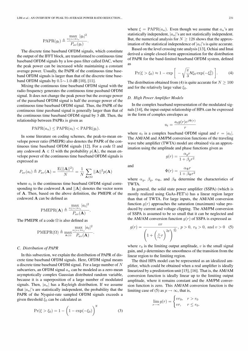
Fig. 2. Block diagram of the proposed PTS scheme with low computational complexity.
or the desired peak power is obtained, iteration stops. For sim-plicity, we assume that only one maximum peak of the OFDMsignal is reduced per iteration in (12).
The PAPR reduction performance of the TR scheme dependson the selection of the PRT set R. But, this problem is knownas NP-hard, because the kernel p must be optimized over allpossible discrete sets R. Thus, it cannot be solved for practicalvalues of N . In [37], an efficient method is proposed for select-ing a near optimal PRT set.
G. Tone Injection and Active Constellation Extension
The tone injection (TI) scheme maps each point of the origi-nal constellation into one of several equivalent points in the ex-panded constellation, which results in extra degrees of freedomand can be exploited for PAPR reduction [36].
The active constellation extension (ACE) method is anothertechnique which changes the constellation to reduce the peakpower. TI maps the data onto alternative constellations whichare cyclically extended from the original constellation points.On the other hand, the ACE method maps the data located at theouter constellations onto arbitrary positions that do not decreasethe minimum distance from the other constellation points. Thiscan reduce PAPR and requires a slight increase of average trans-mit power, and it does not require changing or adding any blocksat the receiver.
The ACE algorithm is based on two convex problems of thepeak level constrained signal set and ACE constrained signalset. It can be solved using two main algorithms. One is the pro-jection onto convex set (POCS) method [38] and the other is thesmart gradient project (SGP) method [39]. The POCS algorithmis the optimal solution, but it converges to the desired peak valuetoo slowly. The SGP algorithm is suboptimal, but it efficientlyreduces the peak value and has a small number of iterations. TheSGP algorithm is based on the gradient project method, clippedsignals are multiplied by the gradient step size determined by theapproximate balancing of peak values per iteration. This algo-rithm is more suitable for smaller constellation sizes and largerOFDM block sizes because it has more degrees of freedom forconstellation extension in these conditions.
ACE constraints to maintain the minimum distance may cause
peak regrowth, which increases the average power and theamount of iterations. Allowing reverse extension can reducepeak regrowth to some extent, but it increases BER [40].
IV. MODIFIED PAPR REDUCTION SCHEMES WITHLOW COMPLEXITY
This section investigates the various modifications of the con-ventional PAPR reduction schemes for achieving low computa-tional complexity.
A. PTS Scheme with Low Computational Complexity
The PAPR reduction performance of PTS schemes is betterthan that of the SLM schemes for a given computational com-plexity, but the redundancy of the PTS scheme is larger than thatof the SLM scheme. As the number of subcarriers and the orderof modulation increase, reducing the computational complexitybecomes more important.
The conventional PTS scheme performs as many IFFT oper-ations as the number of subblocks and requires an exhaustivesearch for the OFDM signal with the minimum PAPR over allcombinations of rotating factors. This results in an exponentialincrease in the computational complexity, which is proportionalto the number of subblocks. Many algorithms have been pro-posed for finding suboptimal rotating vectors [41], [42], whichdo not have an exponential increase in the complexity that de-pends on the number of subblocks.
In [43], a new PTS scheme was proposed for reducing thecomputational complexity of IFFTs. Unlike the conventionalPTS scheme, where input symbol vectors are partitioned at theinitial stage, the proposed PTS scheme performs block partition-ing after the first l stages of IFFT. In this scheme, the 2n-pointIFFT based on the decimation-in-time algorithm is divided intotwo parts. The first part is the first l stages of IFFT. The sec-ond part is the remaining n − l stages. In the first l stages ofIFFT, the input symbol vector A is partially IFFT-ed to form anintermediate signal vector a. This intermediate signal vector ispartitioned into V intermediate signal subvectors and then, theremaining n − l stages of IFFT are applied to each of the inter-mediate signal subvectors.

LIM et al.: AN OVERVIEW OF PEAK-TO-AVERAGE POWER RATIO REDUCTION... 235
Let Ti be an N × N symmetric matrix representing the ithstage of IFFT and Qj
i = TjTj−1 · · ·Ti+1Ti, j ≥ i. Then, theN = 2n point IFFT matrix Q can be expressed as Q = Qn−1
0 .Compared to the conventional PTS scheme, the computa-
tional complexity of the proposed PTS scheme is lower, becausethere is a common intermediate signal vector a = Ql−1
0 A forIFFT of V symbol subvectors. When the number of subcarri-ers is N = 2n, the numbers of complex multiplications nmul
and complex additions nadd of the conventional PTS schemeare given by nmul = 2n−1nV and nadd = 2nnV , respec-tively, where V is the number of subblocks. If the intermedi-ate signal is partitioned after the lth stage of IFFT, it is clearthat the numbers of complex computations of the proposed PTSscheme are given as nmul = 2n−1n + 2n−1(n − l)(V − 1)and nadd = 2nn + 2n(n − l)(V − 1). Thus, the computationalcomplexity reduction ratio (CCRR) of the proposed PTS schemeover the conventional PTS scheme is defined as
CCRR=(
1 − complexity of new PTScomplexity of conventional PTS
)× 100
=(
1 − 1V
)l
n× 100 (%).
It is shown that the optimal value for n− l does not depend onthe number of subcarriers and it is around five when the numberof subcarriers is between 256 and 8192. In the case of N =2048, V = 8, and n − l = 5, the proposed PTS scheme reducesthe computational complexity by 48% while the proposed PTSscheme has almost the same PAPR reduction performance asthat of the conventional one.
B. SLM Scheme with Low Computational Complexity
In this subsection, we investigate three modified SLMschemes with low computational complexity.
B.1 FFT Partitioning Scheme
A new SLM scheme with low computational complexity isproposed in [44]. This is a method for applying the SLM schemeto the intermediate stage of IFFT rather than the first stage as inthe previous subsection. In this scheme, the N point IFFT basedon decimation-in-time algorithm is partitioned into two parts,i.e., the first l stages and the remaining n − l stages. To makealternative OFDM signals, we multiply the different U phasesequences, Pu, 1 ≤ u ≤ U , using the signal in the interme-diate lth stage of IFFT. Based on the proposed SLM scheme,the computational complexity is reduced compared to the con-ventional SLM scheme, because it uses a common IFFT upto lstages and then the SLM scheme is applied to the intermediatestage IFFTed signals.
Since the proposed SLM scheme is performed using a stage-by-stage IFFT approach, we denote ith stage of IFFT as Ti. Thecomputational complexity can be reduced by the common IFFToperation Ql−1
0 = Tl−1Tl−1· · ·T0. The output signal corre-sponding to the phase sequence in the proposed SLM scheme acan be expressed as
a = Tn· · ·Tk+1PTk· · ·T1A (13)
where P is a 2n−l×2n−l diagonal block matrix, i.e., each 2l×2l
subblock of P is either ±I2l . Here, I2l is the 2l × 2l identitymatrix.
When the number of subcarriers is N = 2n, the numbersof complex multiplications nmul and complex additions nadd ofthe conventional SLM scheme are given by nmul = 2n−1nUand nadd = 2nnU , respectively, where U is the total number ofphase sequences. If the phase sequences are multiplied after thelth stage of IFFT, the numbers of complex computations of theproposed SLM scheme are given by nmul = 2n−1n+2n−1(n−l)(U − 1) and nadd = 2nn + 2n(n − l)(U − 1).
The proposed SLM scheme has almost the same PAPR reduc-tion performance as that of the conventional SLM scheme forn−l = 5 and 16-QAM constellation. In the case of n−l = 5, theproposed SLM OFDM system reduces the computational com-plexity by 41∼51% as U increases from 4 to 16.
B.2 Alternative OFDM Signal Combining Scheme
In order to achieve a large PAPR reduction in the conventionalSLM scheme, we have to generate a sufficiently large number ofalternative OFDM signal vectors, which cause a high computa-tional complexity because IFFT must be performed to gener-ate each alternative OFDM signal vector. Therefore, it is desir-able to reduce the number of IFFTs and avoid degradation of thePAPR reduction performance [45].
Let ai and ak be the alternative OFDM signal vectors, gen-erated by the conventional SLM scheme as in (8). Based on lin-ear property of the Fourier transform, the linear combination ofthese two vectors can be given as
ai,k = ciai + ckak
= ciQ(A ⊗ Pi) + ckQ(A ⊗ Pk)= Q(A ⊗ (ciPi + ckPk)) (14)
where ci and ck are complex numbers. If each element of thevector ciPi + ckPk in (14) has a unit magnitude, ciPi + ckPk
can be also used as a phase sequence for the SLM scheme andai,k can be considered as the corresponding alternative OFDMsignal vector. Therefore, if we have alternative OFDM signalvectors ai and ak, another alternative OFDM signal vector ai,k
can be obtained, which avoids the need for IFFT. Note that thephase sequence ciPi + ckPk is not statistically independent ofPi and Pk. Here, we investigate how to make each element ofciPi+ckPk a unit magnitude, in the condition that each elementof the phase sequences Pi and Pk has a unit magnitude. Clearly,the elements of the vector ciPi + ckPk have a unit magnitudeif the following conditions are satisfied:
i) Each element of Pi and Pk has a value in {+1,−1};ii) ci = ±1/
√2 and ck = ±j/
√2.
Since the two alternative OFDM signal vectors generatedfrom the phase sequences ±(ciPi+ckPk) have the same PAPR,we only consider the case of ci = 1/
√2 and ck = ±j/
√2.
Since |ci|2 = |ck|2 = 1/2, the average power of ai,k is equal tohalf the sum of the average power of ai and ak. Using U binaryphase sequences, 2
(U2
)additional phase sequences are obtained,
where(U2
)= U(U − 1)/2. Thus, the total U2 phase sequences
236 JOURNAL OF COMMUNICATIONS AND NETWORKS, VOL. 11, NO. 3, JUNE 2009
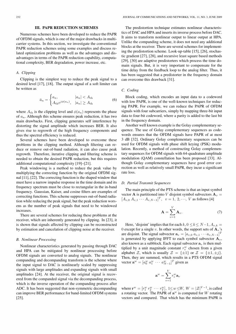
Fig. 3. Block diagram of the proposed SLM scheme with low computational complexity.
are obtained as
{P1,P2, · · · ,PU ,1√2(P1 ± jP2),
1√2(P1 ± jP3), · · ·, 1√
2(PU−1 ± jPU )}.
By combining each pair among U alternative OFDM sig-nal vectors au obtained by using U binary phase sequences asabove, a set S of U2 alternative OFDM signal vectors is gener-ated as
S={au| 1 ≤ u ≤ U2}={au| 1 ≤ u ≤ U}
∪{
1√2(ai + jak),
1√2(ai − jak) | 1 ≤ i < k ≤ U
}(15)
where only U IFFTs and the additional summations of U2 − Upairs of OFDM signal vectors are needed. However, the compu-tational complexity for the summations of OFDM signal vectorsis negligible compared with that of IFFT.
The modified SLM scheme with U binary phase sequencescan be compared with the conventional SLM scheme withU2 binary phase sequences. These two schemes show a sim-ilar PAPR reduction performance for a small U . However, asU increases, the PAPR reduction performance of the modi-fied scheme becomes worse than that of the conventional SLMscheme with U2 binary phase sequences, because U2 phase se-quences of the modified scheme are statistically correlated.
B.3 SLM Scheme with Conversion Matrix
Let Pu = diag(Pu1 , Pu
2 , · · ·, PuN−1) be an N × N diagonal
matrix. Then, alternative OFDM signal vectors are written as
au = QPuA = QPuQ−1a = Kua (16)
where Ku = QPuQ−1 is called a conversion matrix.In [46], Wang proposed a new SLM scheme which reduces
the computational complexity by substituting the conversion
matrix for IFFT. The proposed scheme generates the alterna-tive OFDM signal vectors by multiplying the original OFDMsignal vector by the conversion matrices where the number ofnonzero elements is 4N and the nonzero elements belong to theset {±1,±j}. Thus, the conversion with Ku requires only 3Ncomplex additions.
For example for N = 16 and Pu = [1 j 1 −j 1 j 1 −j 1 j 1−j 1 j 1−j]T , the ith column vector Ωu
i of the conversion matrixKu is expressed as
Ωui = [1 0 0 0 −1 0 0 0 1 0 0 0 1 0 0 0]T((i)), 0 ≤ i ≤ 15
where [·]((i)) is a circularly down-shifted version of column vec-tor [·] by i. Since all the column vectors only have four nonzeroelements, the number of nonzero elements of the conversion ma-trix is 64 (= 4 × 16).
It is worth mentioning that the phase sequence must have pe-riodicity in order to maintain 4N nonzero elements of the con-version matrix and this leads to the degradation of the PAPRreduction performance.
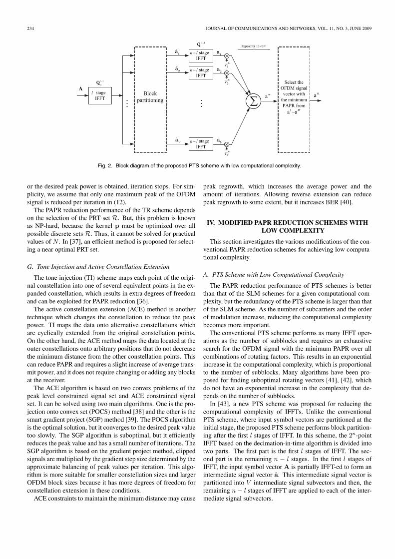
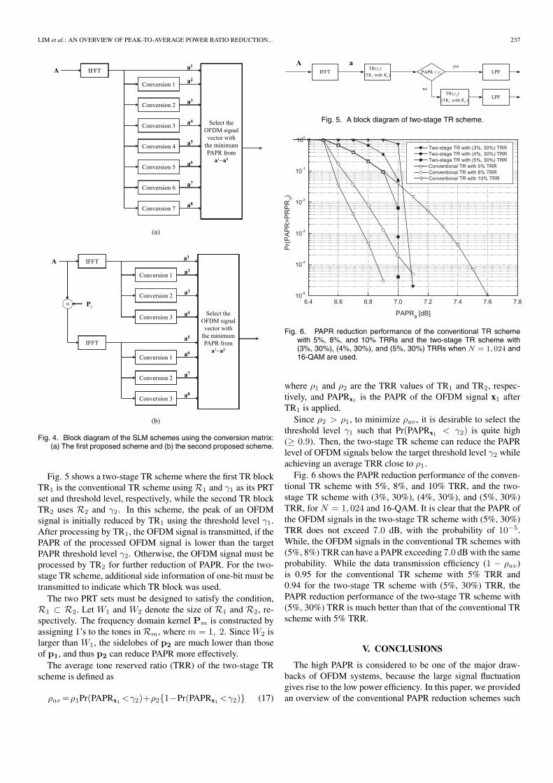
Figs. 4(a) and 4(b) show examples of the proposed SLMschemes in [46]. The first scheme generates eight alternativeOFDM signal vectors from only one IFFT and seven conver-sions while the second scheme uses two IFFTs and six con-versions. In the second scheme, an input symbol vector of thesecond IFFT is transformed via multiplication by the randomlygenerated phase sequence Pz .
Based on the simulation result, the first SLM scheme hasslightly worse PAPR reduction performance and the secondSLM one shows almost the same PAPR reduction performanceas the conventional SLM scheme.
C. Multi-Stage TR Scheme
A multi-stage TR scheme was proposed in order to achieve alow PAPR that has a reduced data rate loss [47]. The multi-stageTR scheme adaptively selects one of several PRT sets accordingto the PAPR of the OFDM signal while the PRT set is fixed forthe conventional TR scheme. In fact, the multi-stage TR schemeutilizes the conventional TR schemes in a sequential manner.
LIM et al.: AN OVERVIEW OF PEAK-TO-AVERAGE POWER RATIO REDUCTION... 237
(a)
(b)
Fig. 4. Block diagram of the SLM schemes using the conversion matrix:(a) The first proposed scheme and (b) the second proposed scheme.
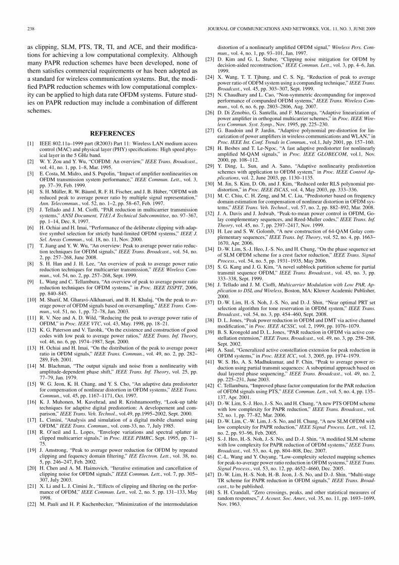
Fig. 5 shows a two-stage TR scheme where the first TR blockTR1 is the conventional TR scheme using R1 and γ1 as its PRTset and threshold level, respectively, while the second TR blockTR2 uses R2 and γ2. In this scheme, the peak of an OFDMsignal is initially reduced by TR1 using the threshold level γ1.After processing by TR1, the OFDM signal is transmitted, if thePAPR of the processed OFDM signal is lower than the targetPAPR threshold level γ2. Otherwise, the OFDM signal must beprocessed by TR2 for further reduction of PAPR. For the two-stage TR scheme, additional side information of one-bit must betransmitted to indicate which TR block was used.
The two PRT sets must be designed to satisfy the condition,R1 ⊂ R2. Let W1 and W2 denote the size of R1 and R2, re-spectively. The frequency domain kernel Pm is constructed byassigning 1’s to the tones in Rm, where m = 1, 2. Since W2 islarger than W1, the sidelobes of p2 are much lower than thoseof p1, and thus p2 can reduce PAPR more effectively.
The average tone reserved ratio (TRR) of the two-stage TRscheme is defined as
ρav =ρ1Pr(PAPRx1 <γ2)+ρ2{1−Pr(PAPRx1 <γ2)} (17)
Fig. 5. A block diagram of two-stage TR scheme.
Fig. 6. PAPR reduction performance of the conventional TR schemewith 5%, 8%, and 10% TRRs and the two-stage TR scheme with(3%, 30%), (4%, 30%), and (5%, 30%) TRRs when N = 1, 024 and16-QAM are used.
where ρ1 and ρ2 are the TRR values of TR1 and TR2, respec-tively, and PAPRx1 is the PAPR of the OFDM signal x1 afterTR1 is applied.
Since ρ2 > ρ1, to minimize ρav , it is desirable to select thethreshold level γ1 such that Pr(PAPRx1 < γ2) is quite high(≥ 0.9). Then, the two-stage TR scheme can reduce the PAPRlevel of OFDM signals below the target threshold level γ2 whileachieving an average TRR close to ρ1.
Fig. 6 shows the PAPR reduction performance of the conven-tional TR scheme with 5%, 8%, and 10% TRR, and the two-stage TR scheme with (3%, 30%), (4%, 30%), and (5%, 30%)TRR, for N = 1, 024 and 16-QAM. It is clear that the PAPR ofthe OFDM signals in the two-stage TR scheme with (5%, 30%)TRR does not exceed 7.0 dB, with the probability of 10−5.While, the OFDM signals in the conventional TR schemes with(5%, 8%) TRR can have a PAPR exceeding 7.0 dB with the sameprobability. While the data transmission efficiency (1 − ρav)is 0.95 for the conventional TR scheme with 5% TRR and0.94 for the two-stage TR scheme with (5%, 30%) TRR, thePAPR reduction performance of the two-stage TR scheme with(5%, 30%) TRR is much better than that of the conventional TRscheme with 5% TRR.
V. CONCLUSIONS
The high PAPR is considered to be one of the major draw-backs of OFDM systems, because the large signal fluctuationgives rise to the low power efficiency. In this paper, we providedan overview of the conventional PAPR reduction schemes such
238 JOURNAL OF COMMUNICATIONS AND NETWORKS, VOL. 11, NO. 3, JUNE 2009
as clipping, SLM, PTS, TR, TI, and ACE, and their modifica-tions for achieving a low computational complexity. Althoughmany PAPR reduction schemes have been developed, none ofthem satisfies commercial requirements or has been adopted asa standard for wireless communication systems. But, the modi-fied PAPR reduction schemes with low computational complex-ity can be applied to high data rate OFDM systems. Future stud-ies on PAPR reduction may include a combination of differentschemes.
REFERENCES[1] IEEE 802.11a–1999 part (R2003) Part 11: Wireless LAN medium access
control (MAC) and physical layer (PHY) specifications: High speed phys-ical layer in the 5 GHz band.
[2] W. Y. Zou and Y. Wu, “COFDM: An overview,” IEEE Trans. Broadcast.,vol. 41, no. 1, pp. 1–8, Mar. 1995.
[3] E. Costa, M. Midro, and S. Pupolin, “Impact of amplifier nonlinearities onOFDM transmission system performance,” IEEE Commun. Lett., vol. 3,pp. 37–39, Feb. 1999.
[4] S. H. Muller, R. W. Bauml, R. F. H. Fischer, and J. B. Huber, “OFDM withreduced peak to average power ratio by multiple signal representation,”Ann. Telecommun., vol. 52, no. 1–2, pp. 58–67, Feb. 1997.
[5] J. Tellado and J. M. Cioffi, “PAR reduction in multicarrier transmissionsystems,” ANSI Document, T1E1.4 Technical Subcommittee, no. 97–367,pp. 1–14, Dec. 8, 1997.
[6] H. Ochiai and H. Imai, “Performance of the deliberate clipping with adap-tive symbol selection for strictly band-limited OFDM systems,” IEEE J.Sel. Areas Commun., vol. 18, no. 11, Nov. 2000.
[7] T. Jiang and Y. W. Wu, “An overview: Peak to average power ratio reduc-tion techniques for OFDM signals,” IEEE Trans. Broadcast., vol. 54, no.2, pp. 257–268, June 2008.
[8] S. H. Han and J. H. Lee, “An overview of peak to average power ratioreduction techniques for multicarrier transmission,” IEEE Wireless Com-mun., vol. 54, no. 2, pp. 257–268, Sept. 1999.
[9] L. Wang and C. Tellambura, “An overview of peak to average power ratioreduction techniques for OFDM systems,” in Proc. IEEE ISSPIT, 2006,pp. 840–845.
[10] M. Sharif, M. Gharavi-Alkhansari, and B. H. Khalaj, “On the peak to av-erage power of OFDM signals based on oversampling,” IEEE Trans. Com-mun., vol. 51, no. 1, pp. 72–78, Jan. 2003.
[11] R. V. Nee and A. D. Wild, “Reducing the peak to average power ratio ofOFDM,” in Proc. IEEE VTC, vol. 43, May. 1998, pp. 18–21.
[12] K. G. Paterson and V. Tarohk, “On the existence and construction of goodcodes with low peak to average power ratios,” IEEE Trans. Inf. Theory,vol. 46, no. 6, pp. 1974–1987, Sept. 2000.
[13] H. Ochiai and H. Imai, “On the distribution of the peak to average powerratio in OFDM signals,” IEEE Trans. Commun., vol. 49, no. 2, pp. 282–289, Feb. 2001.
[14] M. Blachman, “The output signals and noise from a nonlinearity withamplitude-dependent phase shift,” IEEE Trans. Inf. Theory, vol. 25, pp.77–79, Jan. 1979.
[15] W. G. Jeon, K. H. Chang, and Y. S. Cho, “An adaptive data predistorterfor compensation of nonlinear distortion in OFDM systems,” IEEE Trans.Commun., vol. 45, pp. 1167–1171, Oct. 1997.
[16] K. J. Muhonen, M. Kavehrad, and R. Krishnamoorthy, “Look-up tabletechniques for adaptive digital predistortion: A developement and com-parison,” IEEE Trans. Veh. Technol., vol.49, pp.1995–2002, Sept. 2000.
[17] L. Cimini, “Analysis and simulation of a digital mobile channel usingOFDM,” IEEE Trans. Commun., vol. com-33, no. 7, July 1985.
[18] R. O’neil and L. Lopes, “Envelope variations and spectral splatter inclipped multicarrier signals,” in Proc. IEEE PIMRC, Sept. 1995, pp. 71–75.
[19] J. Amstrong, “Peak to average power reduction for OFDM by repeatedclipping and fequency domain filtering,” IEE Electron. Lett., vol. 38, no.5, pp. 246–247, Feb. 2002.
[20] H. Chen and A. M. Haimovich, “Iterative estimation and cancellation ofclipping noise for OFDM signals,” IEEE Commun. Lett., vol. 7, pp. 305–307, July 2003.
[21] X. Li and L. J. Cimini Jr., “Effects of clipping and filtering on the perfor-mance of OFDM,” IEEE Commun. Lett., vol. 2, no. 5. pp. 131–133, May1998.
[22] M. Pauli and H. P. Kuchenbecker, “Minimization of the intermodulation
distortion of a nonlinearly amplified OFDM signal,” Wireless Pers. Com-mun., vol. 4, no. 1, pp. 93–101, Jan. 1997.
[23] D. Kim and G. L. Stuber, “Clipping noise mitigation for OFDM bydecision-aided reconstruction,” IEEE Commun. Lett., vol. 3, pp. 4–6, Jan.1999.
[24] X. Wang, T. T. Tjhung, and C. S. Ng, “Reduction of peak to averagepower ratio of ODFM system using a companding technique,” IEEE Trans.Broadcast., vol. 45, pp. 303–307, Sept. 1999.
[25] N. Chaudhary and L. Cao, “Non-symmetric decompanding for improvedperformance of companded OFDM systems,” IEEE Trans. Wireless Com-mun., vol. 6, no. 6, pp. 2803–2806, Aug. 2007.
[26] D. Di Zenobio, G. Santella, and F. Mazzenga, “Adaptive linearization ofpower amplifier in orthogonal multicarrier schemes,” in Proc. IEEE Wire-less Commun. Syst. Symp., Nov. 1995, pp. 225–230.
[27] G. Baudoin and P. Jardin, “Adaptive polynomial pre-distortion for lin-earization of power amplifiers in wireless communications and WLAN,” inProc. IEEE Int. Conf. Trends in Commun., vol.1, July 2001, pp. 157–160.
[28] H. Besbes and T. Le-Ngoc, “A fast adaptive predistorter for nonlinearlyamplified M-QAM signals,” in Proc. IEEE GLOBECOM, vol.1, Nov.2000, pp. 108–112.
[29] Y. Ding, L. Sun, and A. Sano, “Adaptive nonlinearity predistortionschemes with application to OFDM system,” in Proc. IEEE Control Ap-plications, vol. 2, June 2003, pp. 1130–1135.
[30] M. Jin, S. Kim, D. Oh, and J. Kim, “Reduced order RLS polynomial pre-distortion,” in Proc. IEEE ISCAS, vol. 4, May 2003, pp. 333–336.
[31] M. C. Chiu, C. H. Zeng, and M. C. Liu, “Predistorter based on frequencydomain estimation for compensation of nonlinear distortion in OFDM sys-tems,” IEEE Trans. Veh. Technol., vol. 57, no. 2, pp. 882–892, Mar. 2008.
[32] J. A. Davis and J. Jedwab, “Peak-to-mean power control in OFDM, Go-lay complementary sequences, and Reed-Muller codes,” IEEE Trans. Inf.Theory, vol. 45, no. 7, pp. 2397–2417, Nov. 1999.
[33] H. Lee and S. W. Golomb, “A new construction of 64-QAM Golay com-plementary sequences,” IEEE Trans. Inf. Theory, vol. 52, no. 4, pp. 1663–1670, Apr. 2006.
[34] D.-W. Lim, S.-J. Heo, J.-S. No, and H. Chung, “On the phase sequence setof SLM OFDM scheme for a crest factor reduction,” IEEE Trans. SignalProcess., vol. 54, no. 5, pp. 1931–1935, May 2006.
[35] S. G. Kang and J. G. Kim, “A novel subblock partition scheme for partialtransmit sequence OFDM,” IEEE Trans. Broadcast., vol. 45, no. 3, pp.333–338, Sept. 1999.
[36] J. Tellado and J. M. Cioffi, Multicarrier Modulation with Low PAR, Ap-plication to DSL and Wireless, Boston, MA: Kluwer Academic Publisher,2000.
[37] D.-W. Lim, H.-S. Noh, J.-S. No, and D.-J. Shin, “Near optimal PRT setselection algorithm for tone reservation in OFDM system,” IEEE Trans.Broadcast., vol. 54, no. 3, pp. 454–460, Sept. 2008.
[38] D. L. Jones, “Peak power reduction in OFDM and DMT via active channelmodification,” in Proc. IEEE ACSSC, vol. 2, 1999, pp. 1076–1079.
[39] B. S. Krongold and D. L. Jones, “PAR reduction in OFDM via active con-stellation extension,” IEEE Trans. Broadcast., vol. 49, no. 3, pp. 258–268,Sept. 2002.
[40] A. Saul, “Generalized active constellation extension for peak reduction inOFDM systems,” in Proc. IEEE ICC, vol. 3, 2005, pp. 1974–1979.
[41] W. S. Ho, A. S. Madhukumar, and F. Chin, “Peak to average power re-duction using partial transmit sequences: A suboptimal approach based ondual layered phase sequencing,” IEEE Trans. Broadcast., vol. 49, no. 2,pp. 225–231, June 2003.
[42] C. Tellambura, “Improved phase factor computation for the PAR reductionof OFDM signals using PTS,” IEEE Commun. Lett., vol. 5, no. 4, pp. 135–137, Apr. 2001.
[43] D.-W. Lim, S.-J. Heo, J.-S. No, and H. Chung, “A new PTS OFDM schemewith low complexity for PAPR reduction,” IEEE Trans. Broadcast., vol.52, no. 1, pp. 77–82, Mar. 2006.
[44] D.-W. Lim, C.-W. Lim, J.-S. No, and H. Chung, “A new SLM OFDM withlow complexity for PAPR reduction,” IEEE Signal Process. Lett., vol. 12,no. 2, pp. 93–96, Feb. 2005.
[45] S.-J. Heo, H.-S. Noh, J.-S. No, and D.-J. Shin, “A modified SLM schemewith low complexity for PAPR reduction of OFDM systems,” IEEE Trans.Broadcast., vol. 53, no. 4, pp. 804–808, Dec. 2007.
[46] C.-L. Wang and Y. Ouyang, “Low-complexity selected mapping schemesfor peak-to-average power ratio reduction in OFDM systems,” IEEE Trans.Signal Process., vol. 53, no. 12, pp. 4652–4660, Dec. 2005.
[47] D.-W. Lim, H.-S. Noh, H.-B. Jeon, J.-S. No, and D.-J. Shin, “Multi-stageTR scheme for PAPR reduction in OFDM signals,” IEEE Trans. Broad-cast., to be published.
[48] S. H. Crandall, “Zero crossings, peaks, and other statistical measures ofrandom responses,” J. Acoust. Soc. Amer., vol. 35, no. 11, pp. 1693–1699,Nov. 1963.

LIM et al.: AN OVERVIEW OF PEAK-TO-AVERAGE POWER RATIO REDUCTION... 239
[49] T. Jiang and G. Zhu, “Nonlinear companding transform for reducing peakto average power ratio of OFDM signals,” IEEE Trans. Broadcast., vol.50, pp. 342–346, Sept. 2004.
[50] T. Jiang, Y. Yang, and Y.-H. Song, “Exponential companding techniquesfor PAPR reduction in OFDM systems,” IEEE Trans. Broadcast., vol. 51,no. 2, pp. 244–248, June 2005.
[51] T. Jiang, W. Yao, P. Guo, Y. Song, and D. Qu, “Two novel nonlinear com-panding schemes with iterative receiver to reduce PAPR in multi-carriermodulation systems,” IEEE Trans. Broadcast., vol. 52, no. 2, pp. 268–273,June 2006.
[52] O. Kwon and Y. Ha, “Multi-carrier PAP reduction method using sub-optimal PTS with threshold,” IEEE Trans. Broadcast., vol. 49, no. 2, pp.232–236, June 2003.
[53] T. May and H. Rohling, “Reducing the peak to average power ratio inOFDM radio transmission systems,” in Proc. IEEE VTC, May 1998, pp.2774–2778.
[54] H. Nikookar and K. S. Lidsheim, “Random phase updating algorithm forOFDM transmission with low PAPR,” IEEE Trans. Broadcast., vol. 48,no. 2, pp. 123–128, June 2002.
[55] S. O. Rice, “Mathematical analysis of random noise,” Bell Syst. J., vol. 23,no. 3, pp. 282–332, July 1944.
[56] H. Saedi, M. Sharif, and F. Marvasti, “Clipping noise cancellation inOFDM systems using oversampled signal reconstruction,” IEEE Commun.Lett., vol. 6, pp. 73–75, Feb. 2002.
Dae-Woon Lim received the B.S. and M.S. degreesin Department of Electrical Engineering from KAIST,Daejeon, Korea, in 1994 and 1997, respectively. In2006, he received the Ph.D. degree in Electrical En-gineering and Computer Science from Seoul NationalUniversity. From 1997 to 2002 he was with LG Indus-trial Systems as a Senior Research Engineer, where hedeveloped recognition algorithm, real-time trackingalgorithm, and electric toll collection system. He iscurrently an Assistant Professor in Department of In-formation and Communication Engineering at Dong-
guk University, Seoul, Korea. His research interests are in the area of signalprocessing, wireless communications, and channel coding.
Seok-Joong Heo received the B.S. degree in Electri-cal Engineering from Yonsei University, Seoul, Ko-rea, in 2003 and M.S. degree in Electrical Engineer-ing from Seoul National University, Seoul, Korea, in2005. He is currently a Ph.D. candidate in GraduateSchool of Seoul National University, Seoul, Korea.His research area is OFDM, space-time codes, and er-ror correcting codes.
Jong-Seon No received the B.S. and M.S.E.E. degreesin Electronics Engineering from Seoul National Uni-versity, Seoul, Korea, in 1981 and 1984, respectively,and the Ph.D. degree in Electrical Engineering fromthe University of Southern California, Los Angeles,in 1988. He was a Senior MTS at Hughes NetworkSystems from February 1988 to July 1990. He wasalso an Associate Professor in the Department of Elec-tronic Engineering, Konkuk University, Seoul, Korea,from September 1990 to July 1999. He joined the fac-ulty of the Department of Electrical Engineering and
Computer Science, Seoul National University, in August 1999, where he is cur-rently a Professor. His area of research interests includes error-correcting codes,sequences, cryptography, space-time codes, LDPC codes, and wireless commu-nication systems.