AN OVERVIEW OF MEASURES FOR SHIP’S ENERGY...
12
1. Dunja LEGOVIĆ, Faculty of Engineering, University of Rijeka, Vukovarska 58, 51000 Rijeka, [email protected] (corresponding author) 2. Roko DEJHALLA, Faculty of Engineering, University of Rijeka, Vukovarska 58, 51000 Rijeka, [email protected] AN OVERVIEW OF MEASURES FOR SHIP’S ENERGY EFFICIENCY IMPROVEMENT Abstract The current state of ship energy efficiency measures which are being taken to improve ship efficiency, reduce fuel consumption and lower emissions is presented. Regarding design and construction of a new vessel, the optimization of the hull, appendages, and propulsion systems is discussed. Furthermore, devices that are used to improve the efficiency of propellers are introduced, together with a survey of developing technologies aimed at reducing the hull frictional resistance or using renewable energy sources. Finally, regarding fuel efficiency in service, some operational and maintenance measures that can reduce fuel consumption are addressed. Some of the named approaches can be successfully applied to already existing vessels to improve the current performances. Keywords in English: ship energy efficiency, overview PREGLED MJERA ZA POBOLJŠANJE ENERGETSKE UČINKOVITOSTI BRODA Sažetak U radu je prikazano trenutno stanje mjera koje se poduzimaju za poboljšanje učinkovitosti broda s energetskog stajališta, te u vidu smanjenja potrošnje goriva i emisije stakleničkih plinova. Razmatraju se mogućnosti optimizacije trupa, privjesaka i propulzijskih sustava u okviru projektiranja i gradnje broda. Nadalje, navedeni su uređaji koji se koriste za poboljšanje stupnja djelovanja brodskog vijka, zajedno s pregledom tehnologija koje se razvijaju u svrhu smanjenja otpora trenja ili koje primjenjuju obnovljive izvore energije. Naposlijetku, razmatraju se mjere koje se odnose na operativnost i održavanje, a izravno utječu na smanjenje potrošnje goriva u službi. Neki od navedenih pristupa mogu se uspješno primijeniti na već postojeće brodove radi poboljšanja trenutnih značajki. Ključne riječi na hrvatskom: energetska učinkovitost broda, pregled
Transcript of AN OVERVIEW OF MEASURES FOR SHIP’S ENERGY...

1. Dunja LEGOVIĆ, Faculty of Engineering, University of Rijeka, Vukovarska 58, 51000
Rijeka, [email protected] (corresponding author)
2. Roko DEJHALLA, Faculty of Engineering, University of Rijeka, Vukovarska 58, 51000
Rijeka, [email protected]
AN OVERVIEW OF MEASURES FOR SHIP’S ENERGY EFFICIENCY
IMPROVEMENT
Abstract
The current state of ship energy efficiency measures which are being taken to improve ship
efficiency, reduce fuel consumption and lower emissions is presented. Regarding design and
construction of a new vessel, the optimization of the hull, appendages, and propulsion systems
is discussed. Furthermore, devices that are used to improve the efficiency of propellers are
introduced, together with a survey of developing technologies aimed at reducing the hull
frictional resistance or using renewable energy sources. Finally, regarding fuel efficiency in
service, some operational and maintenance measures that can reduce fuel consumption are
addressed. Some of the named approaches can be successfully applied to already existing
vessels to improve the current performances.
Keywords in English: ship energy efficiency, overview
PREGLED MJERA ZA POBOLJŠANJE ENERGETSKE
UČINKOVITOSTI BRODA
Sažetak
U radu je prikazano trenutno stanje mjera koje se poduzimaju za poboljšanje učinkovitosti
broda s energetskog stajališta, te u vidu smanjenja potrošnje goriva i emisije stakleničkih
plinova. Razmatraju se mogućnosti optimizacije trupa, privjesaka i propulzijskih sustava u
okviru projektiranja i gradnje broda. Nadalje, navedeni su uređaji koji se koriste za poboljšanje
stupnja djelovanja brodskog vijka, zajedno s pregledom tehnologija koje se razvijaju u svrhu
smanjenja otpora trenja ili koje primjenjuju obnovljive izvore energije. Naposlijetku,
razmatraju se mjere koje se odnose na operativnost i održavanje, a izravno utječu na smanjenje
potrošnje goriva u službi. Neki od navedenih pristupa mogu se uspješno primijeniti na već
postojeće brodove radi poboljšanja trenutnih značajki.
Ključne riječi na hrvatskom: energetska učinkovitost broda, pregled

XXII. Simpozij Sorta 2016 Pregled mjera za poboljšanje energetske
učinkovitosti broda
2
1. Introduction
In recent years, the world has turned its focus towards cleaner energy sources and the
Fukushima Nuclear Plant disaster in Japan demonstrated the importance of this shift. For
instance, the European Union has set as target to obtain at least 20 percent of its energy from
renewable sources [1]. However, the production of energy is only a part of the equation. It is
equally important that the available resources are used effectively. A part of this consumption
that cannot be neglected is maritime transport. In 2015, United Nations Conference on Trade
and Development Maritime Transport Review estimates an increase of maritime cargo volume
by 300 million tons, taking the total to 9.84 billion tons [2].
Given the sheer volume, it is as expected that there is currently a significant effort in
creating “greener” ships. This concept is mainly based on reducing the fuel consumption of the
vessels. In 2011, IMO introduced regulations that focus on the limits of the CO2 production of
the new built ships, and the regulations keep evolving depending on the deadweight tonnage of
the ships [3]. Matching these limitations is possible by going through optimization processes
for new vessels. In this case, both the vessel’s hull and its appendages should be paid attention
to. In addition to optimization of design, a number of devices are currently in consideration.
These approaches cover basics such as methods of reducing the friction resistance to more novel
approaches such as the integrating renewable energy sources into vessels.
Regardless of the design decisions, the efficiency is subject to alterations based on the
conditions that are encountered during a particular voyage. Captains take decisions regarding
the routing of the vessel, that combine with weather conditions and factor on fuel consumption.
The loaded and ballast conditions change the draft and trim of the ship from the design draft
and affect the performance. Similarly, even under design conditions, calm sea and extreme
weather behaviour of the vessel will not be equal. It is, therefore, important to consider the
efficiency as a variable value as opposed to a constant. The level of maintenance performed on
the vessel then becomes a part of this variable. Both the propeller and the hull conditions reflect
on the outcome.
This work provides an overview of the factors that increase and reduce the efficiency of
the ship under seaway. It starts by briefly detailing the Energy Efficiency Design Index (EEDI),
and discusses how the hull and the propeller may be optimized to match the targets. Next, the
devices that can be included for new ships and existing ships are described. The final two
sections describe what applies to both new-built and existing ships, as they concern
maintenance and decision making.
2. Energy Efficiency Design Index (EEDI)
Ships commissioned after January 1, 2013, and weighing 400 GT or more, need to meet
the new requirements concerning Energy Efficiency Design Index [4]. The EEDI is based on a
formula to calculate vessel’s energy efficiency, taking into account the ship’s emissions,
capacity and speed. The lower the value, the more energy efficient the ship is and the lower its
negative impact on the environment. The requirements will gradually be tightened: ships built
in 2015 need to meet higher standards than those built in 2013, and in 2020 and 2025 the
standards will increase further. Figure 1 details the limits introduced in years, as a function of
gross tonnage [5].
To satisfy a minimum energy efficiency requirement, ships must not exceed a given
threshold, which depends on its type and size, according to [6]. The method assesses the energy
consumption of a vessel under normal seafaring conditions, taking into account the energy
required for propulsion and the hotel load for the crew. Energy consumed to maintain the cargo
and for manoeuvring or ballasting is not considered:

An overview of measures for ship's energy XXII. Symposium Sorta 2016
efficiency improvement
3
speedcapacity
)(
cargobenefit
emissions COEEDI 2
SFCCP F
(1)
In Equation (1), P represents the individual engine power (main engine, auxiliary engine,
shaft motor) taken at 75% Maximum Continuous Rating. CF is the CO2 emission factor based
on type of fuel used by given engine (main and auxiliary) and SFC is the specific fuel
consumption (main and auxiliary engine). The capacity is given in deadweight tonnage, while
the speed refers to the ship speed at maximum design load conditions.
At present, the EEDI only applies to vessels responsible for the highest emissions when
it comes to maritime pollution. Older vessels are only affected by the standards if they have
undergone a major conversion in recent years. Vessels featuring diesel-electric, gas turbine or
hybrid propulsion are currently not required to meet EEDI standards. RoRo, RoPax, cruise,
offshore and other vessels not explicitly mentioned in the regulations are also exempt. However,
based on the results observed in the first phase of the initiative, the IMO intends to expand the
EEDI to include additional types of ships in the future.
3. Optimization of the hull, appendages, and propulsion system
The shipbuilding industry continually develops new approaches to hull form
optimization. Depending on the capital costs and expected gains in vessel fuel efficiency, two
methods are possible in terms of hull optimization. The first approach is to modify the existing
and partially optimized hull form. This alteration mostly involves modifications to the fore-
body design and stern shape. The second approach is the development of a new design, where
hull particulars, propulsion system, and power plant will be adjusted to reach the maximum
efficiency. This option is suited when a large series of ships is being ordered, due to the high
capital cost of the vessel. In the following sections, both approaches are addressed, and their
feasibility is discussed. A brief summary is provided in Table 1.
3.1. Optimizing Ship Particulars
The transport efficiency can be considered in terms of fuel consumption per tonne-mile of cargo
moved (g/tonne-NM). If larger capacity vessels are employed, the relative fuel consumption
results to be lower due to a higher amount of transported cargo. For example, if the size of a
container ship can be increased from 4500 TEU to 8000 TEU, the fuel consumption for
propulsion per tonne-mile of cargo transported decreases by about 25% [7].
Fig.1. Required EEDI depending on the year of construction [5]
Slika 1. Dozvoljeni EEDI s obzirom na godinu izgradnje [5]
XXII. Simpozij Sorta 2016 Pregled mjera za poboljšanje energetske
učinkovitosti broda
4
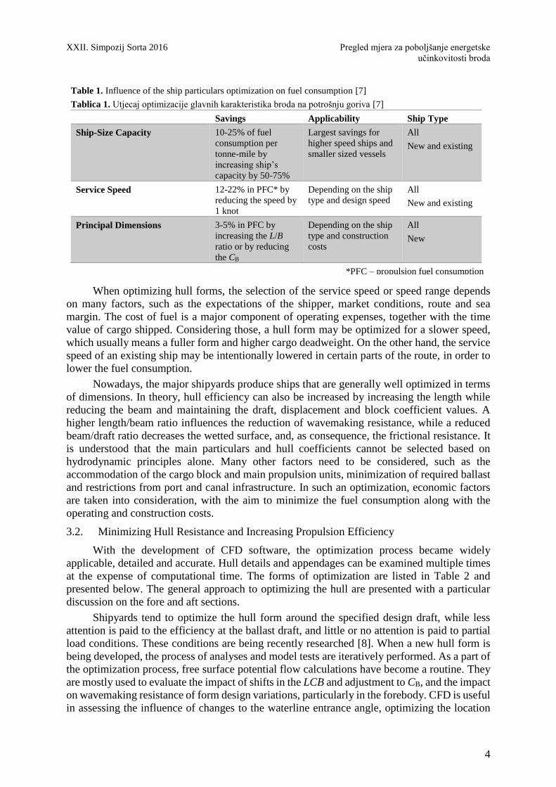
When optimizing hull forms, the selection of the service speed or speed range depends
on many factors, such as the expectations of the shipper, market conditions, route and sea
margin. The cost of fuel is a major component of operating expenses, together with the time
value of cargo shipped. Considering those, a hull form may be optimized for a slower speed,
which usually means a fuller form and higher cargo deadweight. On the other hand, the service
speed of an existing ship may be intentionally lowered in certain parts of the route, in order to
lower the fuel consumption.
Nowadays, the major shipyards produce ships that are generally well optimized in terms
of dimensions. In theory, hull efficiency can also be increased by increasing the length while
reducing the beam and maintaining the draft, displacement and block coefficient values. A
higher length/beam ratio influences the reduction of wavemaking resistance, while a reduced
beam/draft ratio decreases the wetted surface, and, as consequence, the frictional resistance. It
is understood that the main particulars and hull coefficients cannot be selected based on
hydrodynamic principles alone. Many other factors need to be considered, such as the
accommodation of the cargo block and main propulsion units, minimization of required ballast
and restrictions from port and canal infrastructure. In such an optimization, economic factors
are taken into consideration, with the aim to minimize the fuel consumption along with the
operating and construction costs.
3.2. Minimizing Hull Resistance and Increasing Propulsion Efficiency
With the development of CFD software, the optimization process became widely
applicable, detailed and accurate. Hull details and appendages can be examined multiple times
at the expense of computational time. The forms of optimization are listed in Table 2 and
presented below. The general approach to optimizing the hull are presented with a particular
discussion on the fore and aft sections.
Shipyards tend to optimize the hull form around the specified design draft, while less
attention is paid to the efficiency at the ballast draft, and little or no attention is paid to partial
load conditions. These conditions are being recently researched [8]. When a new hull form is
being developed, the process of analyses and model tests are iteratively performed. As a part of
the optimization process, free surface potential flow calculations have become a routine. They
are mostly used to evaluate the impact of shifts in the LCB and adjustment to CB, and the impact
on wavemaking resistance of form design variations, particularly in the forebody. CFD is useful
in assessing the influence of changes to the waterline entrance angle, optimizing the location
Table 1. Influence of the ship particulars optimization on fuel consumption [7]
Tablica 1. Utjecaj optimizacije glavnih karakteristika broda na potrošnju goriva [7]
Savings Applicability Ship Type
Ship-Size Capacity 10-25% of fuel
consumption per
tonne-mile by
increasing ship’s
capacity by 50-75%
Largest savings for
higher speed ships and
smaller sized vessels
All
New and existing
Service Speed 12-22% in PFC* by
reducing the speed by
1 knot
Depending on the ship
type and design speed
All
New and existing
Principal Dimensions 3-5% in PFC by
increasing the L/B
ratio or by reducing
the CB
Depending on the ship
type and construction
costs
All
New
*PFC – propulsion fuel consumption
Fig.1. Required EEDI depending on the year of construction [2]
An overview of measures for ship's energy XXII. Symposium Sorta 2016
efficiency improvement
5
and shape of the fore and aft shoulders, and optimizing the bulbous bow. CFD is to be employed
sequentially, for refinement of shape and elimination of less favourable variations.
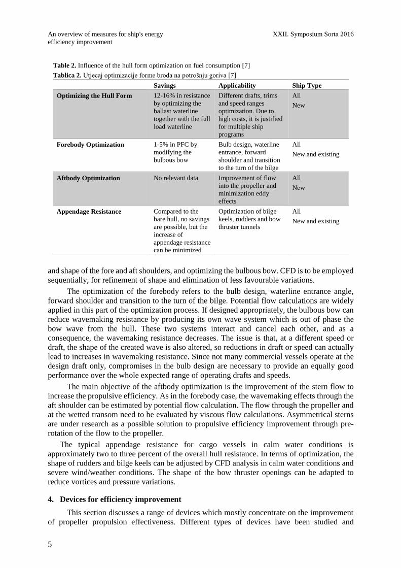
The optimization of the forebody refers to the bulb design, waterline entrance angle,
forward shoulder and transition to the turn of the bilge. Potential flow calculations are widely
applied in this part of the optimization process. If designed appropriately, the bulbous bow can
reduce wavemaking resistance by producing its own wave system which is out of phase the
bow wave from the hull. These two systems interact and cancel each other, and as a
consequence, the wavemaking resistance decreases. The issue is that, at a different speed or
draft, the shape of the created wave is also altered, so reductions in draft or speed can actually
lead to increases in wavemaking resistance. Since not many commercial vessels operate at the
design draft only, compromises in the bulb design are necessary to provide an equally good
performance over the whole expected range of operating drafts and speeds.
The main objective of the aftbody optimization is the improvement of the stern flow to
increase the propulsive efficiency. As in the forebody case, the wavemaking effects through the
aft shoulder can be estimated by potential flow calculation. The flow through the propeller and
at the wetted transom need to be evaluated by viscous flow calculations. Asymmetrical sterns
are under research as a possible solution to propulsive efficiency improvement through pre-
rotation of the flow to the propeller.
The typical appendage resistance for cargo vessels in calm water conditions is
approximately two to three percent of the overall hull resistance. In terms of optimization, the
shape of rudders and bilge keels can be adjusted by CFD analysis in calm water conditions and
severe wind/weather conditions. The shape of the bow thruster openings can be adapted to
reduce vortices and pressure variations.
4. Devices for efficiency improvement
This section discusses a range of devices which mostly concentrate on the improvement
of propeller propulsion effectiveness. Different types of devices have been studied and
Table 2. Influence of the hull form optimization on fuel consumption [7]
Tablica 2. Utjecaj optimizacije forme broda na potrošnju goriva [7]
Savings Applicability Ship Type
Optimizing the Hull Form 12-16% in resistance
by optimizing the
ballast waterline
together with the full
load waterline
Different drafts, trims
and speed ranges
optimization. Due to
high costs, it is justified
for multiple ship
programs
All
New
Forebody Optimization 1-5% in PFC by
modifying the
bulbous bow
Bulb design, waterline
entrance, forward
shoulder and transition
to the turn of the bilge
All
New and existing
Aftbody Optimization No relevant data Improvement of flow
into the propeller and
minimization eddy
effects
All
New
Appendage Resistance Compared to the
bare hull, no savings
are possible, but the
increase of
appendage resistance
can be minimized
Optimization of bilge
keels, rudders and bow
thruster tunnels
All
New and existing
XXII. Simpozij Sorta 2016 Pregled mjera za poboljšanje energetske
učinkovitosti broda
6
developed to either improve the energy performance of a suboptimal ship design and to develop
further a nearly-optimal standard design. What is mostly applied in the list of cases in Tables 3
and 4, are some of the physical phenomena, which would be treated as secondary in the normal
design process, or which are not yet completely understood. Recent developments are mostly
focused on reducing the hull frictional resistance or exploiting readily available natural
resources, such as solar and wind energy. Not all of those devices are currently ready for
implementation. The most prominent reasons can be the high implementation cost of these
technologies, and their difficult integration in the current ship’s design and operation setting.
As it happens, for most new technologies, the economic risk of their adoption cannot always be
readily quantified. For this reason, the utilization of renewable energy is making a rather slow
progress.
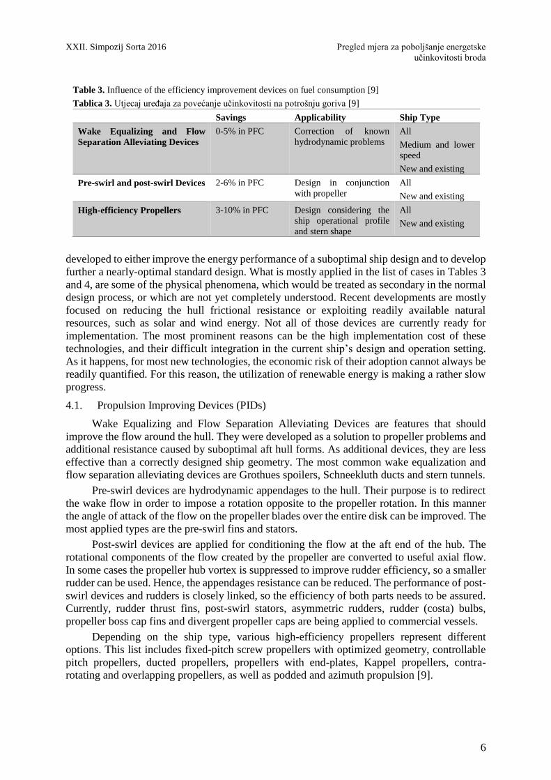
4.1. Propulsion Improving Devices (PIDs)
Wake Equalizing and Flow Separation Alleviating Devices are features that should
improve the flow around the hull. They were developed as a solution to propeller problems and
additional resistance caused by suboptimal aft hull forms. As additional devices, they are less
effective than a correctly designed ship geometry. The most common wake equalization and
flow separation alleviating devices are Grothues spoilers, Schneekluth ducts and stern tunnels.
Pre-swirl devices are hydrodynamic appendages to the hull. Their purpose is to redirect
the wake flow in order to impose a rotation opposite to the propeller rotation. In this manner
the angle of attack of the flow on the propeller blades over the entire disk can be improved. The
most applied types are the pre-swirl fins and stators.
Post-swirl devices are applied for conditioning the flow at the aft end of the hub. The
rotational components of the flow created by the propeller are converted to useful axial flow.
In some cases the propeller hub vortex is suppressed to improve rudder efficiency, so a smaller
rudder can be used. Hence, the appendages resistance can be reduced. The performance of post-
swirl devices and rudders is closely linked, so the efficiency of both parts needs to be assured.
Currently, rudder thrust fins, post-swirl stators, asymmetric rudders, rudder (costa) bulbs,
propeller boss cap fins and divergent propeller caps are being applied to commercial vessels.
Depending on the ship type, various high-efficiency propellers represent different
options. This list includes fixed-pitch screw propellers with optimized geometry, controllable
pitch propellers, ducted propellers, propellers with end-plates, Kappel propellers, contra-
rotating and overlapping propellers, as well as podded and azimuth propulsion [9].
Table 3. Influence of the efficiency improvement devices on fuel consumption [9]
Tablica 3. Utjecaj uređaja za povećanje učinkovitosti na potrošnju goriva [9]
Savings Applicability Ship Type
Wake Equalizing and Flow
Separation Alleviating Devices
0-5% in PFC Correction of known
hydrodynamic problems
All
Medium and lower
speed
New and existing
Pre-swirl and post-swirl Devices 2-6% in PFC Design in conjunction
with propeller
All
New and existing
High-efficiency Propellers 3-10% in PFC Design considering the
ship operational profile
and stern shape
All
New and existing

An overview of measures for ship's energy XXII. Symposium Sorta 2016
efficiency improvement
7
4.2. Skin Friction Reduction
Skin friction is the largest component of viscous resistance. In order to reduce it to some
extent, three methods can be applied: reducing the wetted surface (linear reduction), reducing
speed (quadratic reduction) or improving the interaction between the wetted surface and the
surrounding fluid. The latter approach has been researched through the years, and two types of
systems have been developed: systems that change the behaviour of the fluid - through its
density, viscosity and boundary layer growth, and systems that improve the wetted surface
texture to achieve the best interaction with the fluid. With this aim, air lubrication and hull
surface texturing are currently researched.
The idea behind air lubrication is to force air to stay in touch with those parts of the hull
that would normally be in contact with water. There are two main types of air lubrication: air
cavity systems and micro-bubbles. In air cavity systems, a thin sheet of air is maintained over
the flat portions of a ship’s bottom with the aid of pumps and hull appendages. The goal would
be to obtain a reduction in the wetted surface at the expense of the power needed to supply the
pumps. In the case of micro-bubbles, the density of water in contact with the hull is reduced,
and its viscous behaviour is improved by mixing it with air in the form of micro-bubbles.
Hull surface texturing, on the other hand, advocates an alternative form of coating. In
general, a smooth hull surface is considered as optimal in terms of performance, especially
compared to a fouled hull as a consequence of marine growth. However, it has been
demonstrated that some further benefits can be achieved by adopting particular types of surface
texturing instead of an entirely smooth hull. Certain shapes and sizes of riblets and semi-
spherical microcavities can distort the flow through the boundary layer and thus reduce skin
friction. This type of technology is still in its infancy, and it is not known yet how the correct
shape and size of texture can be achieved and maintained on a ship’s hull. However, some paints
are being developed that might be able to achieve this in the future.
4.3. Renewable Energy
Table 5 provides the wind and solar energies to increase efficiency. The wind has been
used to propel ships for thousands of years. Modern propulsion systems have replaced it only
in the last 150 years, but the benefits that wind power can provide in terms of fuel savings are
seriously considered nowadays. The most researched approaches are towing kites, rotor sails,
Flettner rotors, windmills, and turbosails.
There have also been several attempts of powering vessels by solar energy. The issue is
that, due to the low electrical output per unit surface, they need to extend on a big surface to be
efficient. Therefore, photovoltaic (PV) solar panels are better suited as an additional source of
auxiliary power. Another drawback of PV solar power is the high capital cost of these plants
that have not yet benefited from large scale economies.
Table 4. Influence of the skin friction reduction on fuel consumption [4]
Tablica 4. Utjecaj smanjenja otpora trenja na potrošnju goriva [4]
Savings Applicability Ship Type
Air Lubrication 0-10% in PFC Under research
Unknown maintenance
costs
All
New
Hull Surface Texturing 5-10% in PFC Under research
Unknown maintenance
costs
All
New and existing

XXII. Simpozij Sorta 2016 Pregled mjera za poboljšanje energetske
učinkovitosti broda
8
5. Fuel efficiency in Ship Operation: Voyage Performance Management
The ship’s performance depends on the decisions taken while the ship is on the voyage
as much as it depends on the decisions made in design. Speed, weather, routing and loading
related choices reflect on the environmental impact. The cases are summarized in Table 6.
5.1. Voyage Speed Optimization
The speed of a vessel affects the fuel consumption directly because it is related to the
propulsive power by approximately a third or fourth power relationship. In practice, savings
can be achieved by designing the ship for an economically feasible lower speed [10]. Another
approach is slow steaming, or sailing slower than the design speed on certain sections of the
voyage. The shortcoming of this method is that the main engine and auxiliary systems operate
at low loads, sometimes below standard manufacturer recommendations. This low load
operation can cause accelerated wear of the engine and auxiliary components if not properly
planned and executed. The opportunities for slow steaming can be gained by minimizing the
time spent in port, but that time depends on the organization of the terminal and can hardly be
counted on.
5.2. Weather Routing
The weather routing is a service whose fundamental goal is to select a course from the
departure port to the destination port, providing the safest passage and reliable on-time arrival
while taking into account the actual wind, wave and current conditions expected during the
voyage. The climate data is updated at regular intervals for the vessel’s predicted position and
time, while all the safety limits are checked. Recently the focus shifted from a fast and safe
route to a safe and energy efficient route. In the process, the most critical vessel performance
prediction is the amount of speed reduction in a seaway. The speed reduction depends on the
captain’s decision, so it cannot be easily predicted within a simulation. Weather routing is most
beneficial on longer voyages (over about 1500 NM) where the route is navigationally
unrestricted so that there is a choice of routes, and where weather is a factor on vessel
performance.
5.3. Trim/Draft Optimization
Hull forms are traditionally designed and optimized around one or two primary drafts
assuming zero trim. The distribution of cargo, ballast and consumables often leads to trims
different than that assumed during the design of the hull. For this reason, a vessel in service
may sail a significant portion of its voyages at drafts other than the design draft. The traditional
approach for determining optimum trim is to rely on model tests in calm water to evaluate the
resistance over a full matrix of drafts and trims. In recent years a large number of trim
optimization tools have appeared on the market. They are mostly based on CFD methods to
evaluate the same matrix of drafts and trim with computation rather than physical tests.
Table 5. Influence of the renewable energy devices on fuel consumption [1]
Tablica 5. Utjecaj uređaja za korištenje obnovljivih izvora energije na potrošnju goriva [1]
Savings Applicability Ship Type
Wind Up to 30% in PFC
Limited by superstructure and ship’s
operational profiles
All low-speed
New and existing
Solar Marginal Limited due to low electrical output per
unit surface
All
New and existing

An overview of measures for ship's energy XXII. Symposium Sorta 2016
efficiency improvement
9
5.4. Autopilot Improvements
Rudder movements add drag to the hull and increase resistance. This effect can be reduced
by minimizing the number of rudder movements and the amount of rudder angle that is applied
to maintain course or to perform a change of course. This is true under manual steering as well
as when an autopilot is engaged. Conventional autopilots usually rely on linear relationships
between rudder angle and rate of change of heading. An adaptive system takes feedback on the
rate of response of the ship to a given rudder angle and automatically adjusts the steering control
model. A steering model adapted to actual conditions helps prevent excessively frequent or
large rudder motions (so called hunting) in course-keeping and course-changing modes. The
highest efficiency of the adaptive steering system is obtained if it can be auto-tuned to the
weather and load conditions. A voyage routing or performance tool can integrate these options
into the overall course prediction.
6. Effect of Hull and Propeller Condition in Energy Efficiency
The frictional resistance is significantly affected by the roughness of the surface exposed
to the flow. It is estimated that each 10 μm to 20 μm of additional roughness can increase the
total hull resistance by about 1 percent for full form ships and about 0.5 percent for fine-form
ships at high speeds. In order to minimize a ship’s frictional resistance, the owner must address
both physical and biological roughness of the hull and the propeller. The cases regarding the
effect of maintenance and overall management of the vessel are summarized in Table 7 and
elaborated below.
6.1. Effects of Hull and Propeller Maintenance
The purpose of in-service, underwater hull cleaning is to remove biological roughness or
fouling. Underwater cleaning is accomplished by a diver or a squad with a manually operated
scrubber incorporating some type of rotating brushes or pads. This operation is considered cost
effective if the proper cleaning technique is used so that the surface roughness is not degraded
and the coating material is not removed. For best results, the scheduling of cleaning should be
based either on monitoring of performance indicators (such as fuel consumption) or on regular
pre-cleaning inspections. In both cases, an economically justified threshold is established. In
the planning process some regulatory instruments need to be considered, such as IMO’s MEPC
62/24 [11] that govern the times and locations allowed for the cleaning. These guidelines would
greatly diminish the risk of the spread of aquatic species into new areas, especially the so-called
niche areas (sea chests, thrust tunnels, etc.).
Table 6. Influence of the voyage performance management on fuel consumption [4]
Tablica 6. Utjecaj praćenja plovidbe na potrošnju goriva [4]
Savings Applicability Ship Type
Voyage Speed Optimization 20% in PFC
obtained by speed
reduction of 10%
Biggest improvement for
higher speed ships
All
New and existing
Weather Routing Depending on
weather and voyage
length
Biggest improvement for
long routes in harsh
climates
All
New and existing
Trim/Draft Optimization 1-2% in PFC Biggest improvement for
long routes
All
New and existing
Autopilot Improvements 0-1% in PFC Biggest improvement for
long routes in harsh
climates
All
New and existing
XXII. Simpozij Sorta 2016 Pregled mjera za poboljšanje energetske
učinkovitosti broda
10
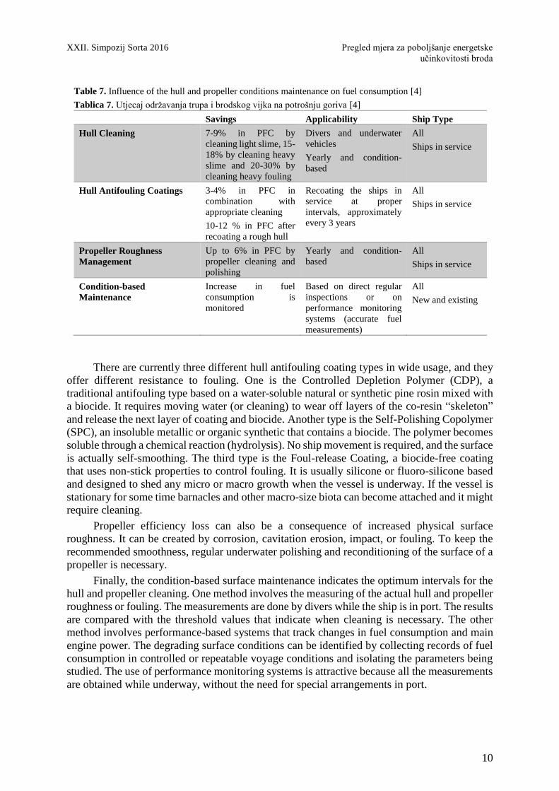
There are currently three different hull antifouling coating types in wide usage, and they
offer different resistance to fouling. One is the Controlled Depletion Polymer (CDP), a
traditional antifouling type based on a water-soluble natural or synthetic pine rosin mixed with
a biocide. It requires moving water (or cleaning) to wear off layers of the co-resin “skeleton”
and release the next layer of coating and biocide. Another type is the Self-Polishing Copolymer
(SPC), an insoluble metallic or organic synthetic that contains a biocide. The polymer becomes
soluble through a chemical reaction (hydrolysis). No ship movement is required, and the surface
is actually self-smoothing. The third type is the Foul-release Coating, a biocide-free coating
that uses non-stick properties to control fouling. It is usually silicone or fluoro-silicone based
and designed to shed any micro or macro growth when the vessel is underway. If the vessel is
stationary for some time barnacles and other macro-size biota can become attached and it might
require cleaning.
Propeller efficiency loss can also be a consequence of increased physical surface
roughness. It can be created by corrosion, cavitation erosion, impact, or fouling. To keep the
recommended smoothness, regular underwater polishing and reconditioning of the surface of a
propeller is necessary.
Finally, the condition-based surface maintenance indicates the optimum intervals for the
hull and propeller cleaning. One method involves the measuring of the actual hull and propeller
roughness or fouling. The measurements are done by divers while the ship is in port. The results
are compared with the threshold values that indicate when cleaning is necessary. The other
method involves performance-based systems that track changes in fuel consumption and main
engine power. The degrading surface conditions can be identified by collecting records of fuel
consumption in controlled or repeatable voyage conditions and isolating the parameters being
studied. The use of performance monitoring systems is attractive because all the measurements
are obtained while underway, without the need for special arrangements in port.
Table 7. Influence of the hull and propeller conditions maintenance on fuel consumption [4]
Tablica 7. Utjecaj održavanja trupa i brodskog vijka na potrošnju goriva [4]
Savings Applicability Ship Type
Hull Cleaning 7-9% in PFC by
cleaning light slime, 15-
18% by cleaning heavy
slime and 20-30% by
cleaning heavy fouling
Divers and underwater
vehicles
Yearly and condition-
based
All
Ships in service
Hull Antifouling Coatings 3-4% in PFC in
combination with
appropriate cleaning
10-12 % in PFC after
recoating a rough hull
Recoating the ships in
service at proper
intervals, approximately
every 3 years
All
Ships in service
Propeller Roughness
Management
Up to 6% in PFC by
propeller cleaning and
polishing
Yearly and condition-
based
All
Ships in service
Condition-based
Maintenance
Increase in fuel
consumption is
monitored
Based on direct regular
inspections or on
performance monitoring
systems (accurate fuel
measurements)
All
New and existing
An overview of measures for ship's energy XXII. Symposium Sorta 2016
efficiency improvement
11
6.2. Overall Energy Efficiency Management
There are a significant number of energy efficiency measures that can and should be
considered by the ship owner or operator in order to minimize fuel consumption, fuel cost and
emissions. To effectively coordinate these measures, a ship’s performance monitoring system
needs to be adequately designed and well-managed. It should include data collection, analysis,
reporting and dissemination to the relevant stakeholders.
The performances of all onboard power consumers should be considered, starting with
the engine systems, down to the pumps and lights. Each component can be tuned to perform at
the optimum efficiency based on manufacturer’s guidelines. Alternatively, components can be
replaced with higher efficiency models or ones that are a better match for the load or service
condition.
For proper energy efficiency management, it is necessary to develop an accurate fuel
consumption measuring system and reliable reporting process. The data should address both
bunker management and energy efficiency measures in a coordinated manner and with
acceptable accuracy.
In order to carefully coordinate the efforts made to improve efficiency, it is suggested that
a well-managed process is undertaken, such as that defined in the Ship Energy Efficiency
Management Plan (SEEMP) regulations. The SEEMP is an amendment to MARPOL Annex
VI that makes a SEEMP mandatory for all new and existing ships as of 1 January 2013, adopted
in July 2011 by IMO. According to [12], each ship shall keep on board a ship specific SEEMP.
The SEEMP implementation consists in four main iterative steps:
1. Planning, which includes the setting of ship-specific, company-specific and human
resources goals and procedures
2. Implementation, consisting in the execution of plans and procedures, together with
recordkeeping
3. Monitoring requires the appropriate tools and systems without burdening the ships’
crew
4. Self-evaluation and improvement, where effectiveness should be evaluated and
feedback should be produced
The scope and detail of the SEEMP can vary, and there are several guidelines already
published for owners and operators to reference.
7. Conclusion
Shipping industry currently aims to advance the world trend in greener energy, by
producing “green” ships and increasing the efficiency of the modern vessels. Considering the
amount of trade on the seaway, the importance of the contribution is apparent. In this regard,
an overview of the current practices was presented in this paper.
Initially, the standards that are developed by the IMO were presented. These rules apply
to new vessels and to ships that have undergone major conversions after 2011. Optimization of
the hull form and the appendages are necessary to match these targets, which were both
elaborated. On the other hand, certain devices may apply to new and older vessels. These
approaches include propulsion improving devices, skin friction reduction and renewable energy
sources, which were described.
It was discussed that the efficiency of a vessel under seaway is not a constant value but a
variable. Decisions taken by the captain, the weather, and the loading conditions affect the
outcome. They were listed with their expected overall contribution. The state of the ship
regarding maintenance was described as the final factor.
XXII. Simpozij Sorta 2016 Pregled mjera za poboljšanje energetske
učinkovitosti broda
12
ACKNOWLEDGEMENT
This work was supported by the University of Rijeka (Contract no.13.09.1.1.05) and by
the Croatian Science Foundation - project 8722.
REFERENCES
[1] European Commission, Renewable Energy Progress Report, Report from the
Commission to the European parliament, the Council, the European economic and social
committee and the Committee of the regions. European Commission Publications Office,
2015.
[2] United Nations Conference on Trade and Development (UNCTAD), Review of Maritime
Transport. United Nations Publication, UNCTAD/RMT/2015, 2015.
[3] Marine Environment Protection Committee (MEPC), 63rd Session. MEPC 63/1, 2011.
[4] The International Council on Clean Transport (ICCT), The Energy Efficiency Design
Index (EEDI) for New Ships. ICCT Policy Update 15, 2011.
[5] MAN Diesel & Turbo, EEDI Energy Efficiency Design Index. MAN Diesel &Turbo
D2366498EN-N2, Germany.
[6] ISO/IEC 15016:2015, Ships and Marine Technology –Guidelines for the Assessment of
Speed and Power Performance by Analysis of Speed Trial Data, First Ed. International
Organization for Standardization (ISO), Geneva, Switzerland, 2015.
[7] ABS, Ship Energy Efficiency Measures Status and Guidance. American Bureau of
Shipping (ABS), 2013.
[8] D. Legovic and R. Dejhalla, “Numerical hydrodynamic optimization of a tanker hull
form,” in Towards Green Marine Energy and Transport, C. Guedes Soares, Dejhalla,
and Pavletic, Eds. London: Taylor & Francis Group, 2015, pp. 75 – 82.
[9] J. S. Carlton, Marine propellers and propulsion, Second ed. Butterworth-Heinemann,
London, 1984.
[10] International Maritime Organization (IMO), Marginal Abatement Costs and Cost-
Effectiveness of Energy-Efficiency Measures. International Maritime Organization
(IMO), MEPC 61/INF.18, 2010.
[11] International Maritime Organization (IMO), Guidelines for the Control and
Management of Ship’s Biofouling to Minimize the Transfer of Invasive Aquatic Species.
IMO Report MEPC 62/24/Add.1, 2011.
[12] International Maritime Organization (IMO), MEPC 62/64/Add.1 Annex 19, Resolution
MEPC.203(2). 2011.


![Untitled-1 [bib.irb.hr]bib.irb.hr/datoteka/966211.Untitled-1.pdf · Title: Untitled-1 Author: KlingonJim Created Date: 10/31/2018 10:54:59 AM](https://static.fdocuments.us/doc/165x107/5f5f17538d2ffd7a217e419d/untitled-1-bibirbhrbibirbhrdatoteka-title-untitled-1-author-klingonjim.jpg)