National Center for Hypersonic Combined Cycle Propulsion June 16, 2011
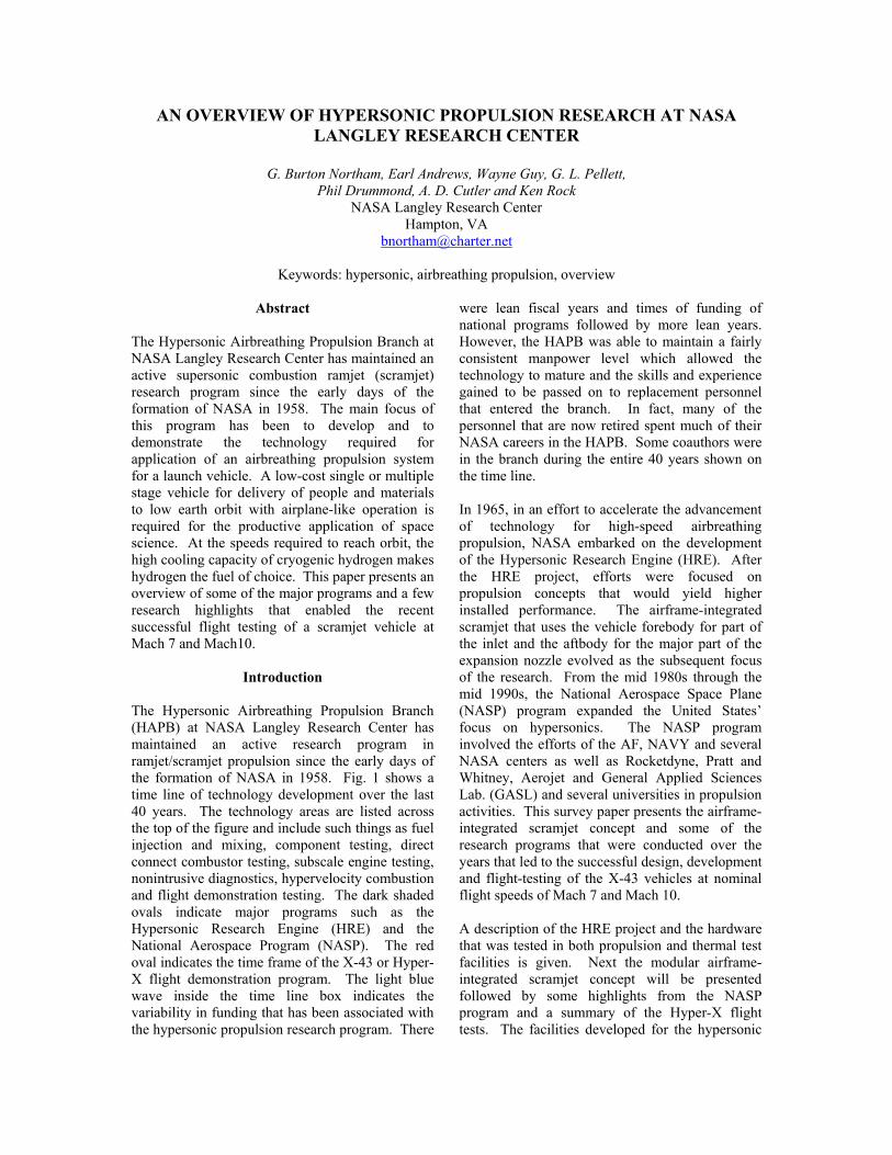
AN OVERVIEW OF HYPERSONIC PROPULSION RESEARCH AT NASA LANGLEY RESEARCH CENTER
G. Burton Northam, Earl Andrews, Wayne Guy, G. L. Pellett,
Phil Drummond, A. D. Cutler and Ken Rock NASA Langley Research Center
Hampton, VA [email protected]
Keywords: hypersonic, airbreathing propulsion, overview
Abstract
The Hypersonic Airbreathing Propulsion Branch at NASA Langley Research Center has maintained an active supersonic combustion ramjet (scramjet) research program since the early days of the formation of NASA in 1958. The main focus of this program has been to develop and to demonstrate the technology required for application of an airbreathing propulsion system for a launch vehicle. A low-cost single or multiple stage vehicle for delivery of people and materials to low earth orbit with airplane-like operation is required for the productive application of space science. At the speeds required to reach orbit, the high cooling capacity of cryogenic hydrogen makes hydrogen the fuel of choice. This paper presents an overview of some of the major programs and a few research highlights that enabled the recent successful flight testing of a scramjet vehicle at Mach 7 and Mach10.
Introduction The Hypersonic Airbreathing Propulsion Branch (HAPB) at NASA Langley Research Center has maintained an active research program in ramjet/scramjet propulsion since the early days of the formation of NASA in 1958. Fig. 1 shows a time line of technology development over the last 40 years. The technology areas are listed across the top of the figure and include such things as fuel injection and mixing, component testing, direct connect combustor testing, subscale engine testing, nonintrusive diagnostics, hypervelocity combustion and flight demonstration testing. The dark shaded ovals indicate major programs such as the Hypersonic Research Engine (HRE) and the National Aerospace Program (NASP). The red oval indicates the time frame of the X-43 or Hyper-X flight demonstration program. The light blue wave inside the time line box indicates the variability in funding that has been associated with the hypersonic propulsion research program. There
were lean fiscal years and times of funding of national programs followed by more lean years. However, the HAPB was able to maintain a fairly consistent manpower level which allowed the technology to mature and the skills and experience gained to be passed on to replacement personnel that entered the branch. In fact, many of the personnel that are now retired spent much of their NASA careers in the HAPB. Some coauthors were in the branch during the entire 40 years shown on the time line.
In 1965, in an effort to accelerate the advancement of technology for high-speed airbreathing propulsion, NASA embarked on the development of the Hypersonic Research Engine (HRE). After the HRE project, efforts were focused on propulsion concepts that would yield higher installed performance. The airframe-integrated scramjet that uses the vehicle forebody for part of the inlet and the aftbody for the major part of the expansion nozzle evolved as the subsequent focus of the research. From the mid 1980s through the mid 1990s, the National Aerospace Space Plane (NASP) program expanded the United States’ focus on hypersonics. The NASP program involved the efforts of the AF, NAVY and several NASA centers as well as Rocketdyne, Pratt and Whitney, Aerojet and General Applied Sciences Lab. (GASL) and several universities in propulsion activities. This survey paper presents the airframe-integrated scramjet concept and some of the research programs that were conducted over the years that led to the successful design, development and flight-testing of the X-43 vehicles at nominal flight speeds of Mach 7 and Mach 10. A description of the HRE project and the hardware that was tested in both propulsion and thermal test facilities is given. Next the modular airframe-integrated scramjet concept will be presented followed by some highlights from the NASP program and a summary of the Hyper-X flight tests. The facilities developed for the hypersonic

propulsion program will be presented followed by an example of combustion diagnostics and computational fluid dynamics research. This paper gives the reader a non-technical, updated overview of the NASA Langley Hypersonic Airbreathing Propulsion Branch program. A similar paper1) was prepared for AIAA in 1986 and contains an extensive list of earlier references by Langley staff and other work supported by NASA related to scramjet technology. The 238 references of the earlier paper also contain a limited number, but by no means all, of the early supersonic combustion work that was supported by the Navy and Air Force. Early U. S. scramjet research in the 1960s and 1970s is covered in a summary report by Walthrup, Anderson and Stull.2) A more recent paper by Andrews 3) gives an excellent summary of the various ramjet and scramjet engines that were developed and tested in the United States. The paper contains 57 references and many detailed figures and drawings of engine configurations as well as a summary of test facilities used.
Hypersonic Research Engine (HRE) In 1964, NASA Dryden and Langley Research Centers undertook the development of the Hypersonic Research Engine (HRE) Project. The goal of the program was to flight test a supersonic research engine on the X-15 research aircraft. Of the four proposed concepts considered for contract support, the Garrett-AiResearch Corp. axis-symmetric, variable-geometry inlet concept was selected. The goal of flight-tests was not realized due to cancellation of the X-15 program prior to the flight test phase of the HRE program. However, the HRE Project continued through 1975 with a research program conducted using ground based research test facilities. Two research engines were constructed and tested. A flight weight, full-scale Structural Assembly Model (SAM) constructed of Hasteloy-X with hydrogen cooling was tested in the NASA Langley 8-Foot High Temperature Tunnel (8-ft. HTT) in 1969-1970. The SAM model is shown in Fig. 2. A full-scale Aerothermodynamic Integration Model (AIM), a boiler-plate model constructed of Nickel-200 using water cooling and hydrogen fuel, was tested in the NASA Lewis Plumbrook Hypersonic Test Facility (HTF) in 1971-1973. The AIM engine is shown in Fig. 3. The success of these tests verified the performance, operability, structural design and control concepts for a complete scramjet engine system.
Airframe-Integrated Scramjet
Several studies of scramjets for airbreathing launch vehicles were conducted in the 1960s. It was determined that, for faster aircraft flight speeds (up to more than ten times the speed of sound), an air breathing propulsion system would be too large to mount under the wings of the vehicle. Therefore, the engine had to be highly integrated with the vehicle; that is, the propulsion system would become the entire undersurface of the vehicle with the forebody providing initial compression of the engine inlet flow and the aftbody acting as the nozzle and expanding the engine exhaust flow. Turbojets were envisioned to be internally imbedded in the vehicle where open-closed flap doors on the forebody would introduce ducted flow to the turbojet engine core. The turbojet would exhaust from the vehicle aftbody. The turbojets would be used for the horizontal take-off to Mach 2.5-3.0 flight speed where ramjet operation would begin. The turbojets would again be used on return flights for low speed horizontal landings. Rocket motors imbedded in the vehicle base or integrated with the ram/scramjets were envisioned for final space insertion (Mach >14). Thus, the mid-speed portion of the flight would be a ram/scramjet engine integrated with the vehicle underside. The propellant weight savings would come by using atmospheric oxygen as the oxidant for as much of the flight regime as possible. For these reasons, after the HRE project, NASA’s efforts were focused on propulsion concepts that would yield higher installed performance: an Airframe-Integrated Scramjet. When constructed using a modular design, this engine concept allows testing of representative single engine modules or flow paths in facilities of reasonable size without having to develop and construct flight vehicle-size test facilities. The first of these engine concepts tested at Langley in the 1978 to 1988 era was the 3-strut rectangular engine. The use of side wall compression and wedge shaped struts to complete the inlet process shortens the inlet and provides additional locations from which to distribute fuel into the compressed air stream. This engine concept was extensively tested in the Langley CHSTF and AHSTF. Guy and coworkers describe these facilities in detail in a 1996 AIAA paper. 4) Due to the short test duration, heat sink models made from nickel-200 or oxygen-free copper were used for these tests. Tunnels were constructed with nozzle exit conditions to simulate engine inlet inflow conditions of flight vehicles operating at

Mach 4.0 and 7.0 flight conditions. The nickel engine that was tested at Mach 4 is shown in Fig. 4, and the copper engine that was tested in the arc heated facility at Mach 7 is shown in Fig. 5. These models were 6 inches wide, 8 inches high and from 60 to 70 inches in length. Tunnel conditions were controlled (within supply limitations) to provide simulation of velocity, temperature and pressure. The fuel distribution, injection location and equivalence ratio in these engines were tailored for the test conditions to produce thrust without combustor-inlet interaction. Guy and Mackley summarize these subscale modular engine test results in a paper at the 4th ISABE meeting. 5) Due to the small scale, lower than desired static pressure resulting from facility limitations and high velocities leading to low residence times, a Silane/Hydrogen mixture was often used as an ignition aid. Silane (SiH4) is a pyrophoric gas that was mixed with hydrogen (20/80 percent by volume) to aid in ignition and, in some cases, flame holding. Some research on Silane as an engine igniter and flame modifier is documented in papers by Beach, et. al., 6) and research studies of silane combustion are presented by Pellett, et. al. 7) The follow-on to the Langley 3-strut model was a strutless sidewall-compression inlet configuration. This configuration, a copper heat-sink model, was 6-in. wide, 7-in. high and 6-ft. long. The sidewalls could be moved in and- out to vary the inlet contraction ratio and/or create rearward facing steps in the isolator/combustor. Some sections were inter-changeable (e.g., various swept leading edges). This variability permitted a wide range of parametric tests; thus, the model was called the Strutless Parametric Engine (SLPE). This engine was tested extensively at flight-simulated conditions at Mach 4.0 and 5.5 in the CHSTF and at Mach 5.5 and 7.0 in the AHSTF. 8) The focus provided by this engine program supported the development of empirical models, cycle analysis tools, and engineering CFD applications.9) A variation of the Strutless Parametric Engine was the Step-Strut Parametric Engine (SSPE). The aft swept inlet sidewalls of the original SLPE were replaced with unswept-leading-edge sidewalls, and a center strut with a stepped leading edge was added. The strut leading edge with the unswept steps produced effects similar to those of a swept leading edge strut; that is, the flow turned down toward the cowl. The steps, however, produced individual shocks that impinged upon the sidewalls without the typical continuous single shock wave
that may cause boundary-layer separation. This step-strut inlet design improved inlet mass capture and flow uniformity while still allowing for acceptable inlet self-starting characteristics. The center strut also allowed fuel to be injected into smaller combustor passage widths to improve mixing/combustion efficiencies.
National AeroSpace Plane Program A large data base of scramjet engine technology was obtained from tests of the Langley 3-Strut and the Parametric Engines. 10) This database was extensively used during the National AeroSpace Plane (NASP) Project. NASP was initiated in 1985 with the goal of developing an experimental X-30 single-stage-to-orbit (SSTO) vehicle. The NASP engines, test facilities and the number of successful tests performed are well summarized.11) The NASP program provided funding for an expansion of the hypersonic propulsion program at Langley. Some of the areas addressed through this funding included the development and improvement of test facilities, dual mode scaramjet flow path analysis techniques, validation of prediction tools, propulsion-airframe integration technology, improved computational methods and validation of predictive techniques through engine testing and diagnostic measurements. A number of model engines were designed and tested under a variety of conditions during this program.3) The first NASP engine, the Government Baseline Engine (GBL), was fabricated in 1985 and tested at GASL. A second GBL model was fabricated in 1986 and tested in the Langley CHSTF at Mach 4.0. The model is shown in Fig. 6 in the low Mach test configuration. The NASP engine contractors were “teamed” in 1990 to develop an engine for demonstration testing. After testing several small scale models, a large-scale model (10 in. x 16 in. x 142 in.), designated the Contractor Demonstration Engine (CDE), was fabricated and tested in the Langley 8-Foot High Temperature Tunnel (8-ft. HTT) at Mach 6.8 simulated flight conditions. The engine being prepared for testing is shown in Fig. 7. The test objectives of the CDE were to demonstrate performance and operability limits of the large-scale integrated scramjet in order to verify flowpath design methods for application to flight. The NASP Program ended in 1994, because of funding and scheduling problems. Although the NASP program did not result in a flight demonstration as initially envisioned, the science and technology developed under the program

provided an explosion of knowledge concerning the issues associated with supersonic mixing/combustion, flow path analysis, CFD and code validation, structures/materials and an enormous upgrade in facilities available for future testing. 12, 13)
Hyper-X Flight Program After more than 40 years of ground-based scramjet research, there was a strong consensus in the hypersonic propulsion community that it was highly desirable to move hypersonic air-breathing technology from the ground laboratory to the flight environment. In response to this desire, the Hyper-X Project was initiated in late 1995 as a joint effort of NASA Langley and Dryden Research Centers .14, 15) The program was designed with a hypersonic vehicle that could be launched from a B-52B airplane and accelerated to hypersonic speeds by a small solid rocket. The Hyper-X vehicle stack is shown in Fig. 8. The Pegasus solid propellant rocket booster was mounted under the wing of the B-52B with the Hyper-X vehicle mounted to the booster through a load carrying adaptor. The mission events are shown in Fig. 9. The vehicle was prepared for launch and installed on the B-52B and carried to an altitude of about 30 thousand feet. The booster was fired to take the vehicle to an altitude close to 95 thousand feet. The booster and the vehicle were then separated, and the scramjet engines ignited. A typical flight path is shown in Fig. 10. The first scramjet flight test was designed for a more conservative Mach 7, and the second test was designed for operation at Mach 10 flight conditions at approximately 95,000 feet altitude. As shown in the figure, the test time was about 10 seconds. This program was based on a vehicle design scaled from the McDonnell-Douglas/Pratt and Whitney Dual-Fuel, Global Reach vehicle study. 16) After several smaller scale tests and a review of the data base generated during the NASP program, an extensive ground test research plan which included sub-scale and full-scale engine tests was developed.17-21) The test plan included both subscale and flight scale testing as shown in Fig. 11. The first test was of a sub-scale partial-width engine installed on a propulsion full-flowpath-simulator (FFS) of the Hyper-X vehicle design. The model (HXEM/FFS), 10 in. wide x 10 in. high x 125 in. long, incorporated an inlet cowl with a hinged moveable door for engine close off and inlet starting. The HXEM/FFS was tested in the 8-Ft. HTT at Mach 6.9 simulated flight conditions. This HXEM/FFS
model provided a Hyper-X concept engine that could be tested while a complete engine/flow-path model of the Hyper-X was being fabricated. The model was removed from the FFS and installed, as planned, in the Langley HXEM in LaRC AHSTF for sub-scale tests at Mach 5.5 and 7.0. These tests were designed to demonstrate that scramjet tests of partial width or modular models were rep-resentative of full-length flowpath tests. Following the HXEM/FFS tests in the 8-ft. HTT, the tunnel was utilized to test a full scale Hyper-X engine and flowpath. The complete Hyper-X engine/flowpath model (an actual flight engine) was mounted on a full flowpath duplication of the vehicle undersurface. The Hyper-X Flight Engine/Vehicle Flowpath Simulator (HXFE/VFS) was 144 in. long and was the first propulsion test of a full-scale, flight scramjet engine with the actual undersurface flow-path of a hypersonic flight vehicle. Although it limited the size of the vehicle, testing the actual size flight vehicle was a risk reduction decision. In conjunction with the 8-ft. HTT and AHSTF tests, many high-speed tests have been performed in the NASA HYPULSE facility at GASL using the Hyper-X Hypulse Scramjet Model (HSM) as shown. The first series of tests was conducted at Mach 7 conditions with the HSM internal flow lines the same as the HXEM. Such tests allowed data comparisons of the models tested in different types of facilities (arc-heated vs. shock-heated pulse tunnel). Mach 10 tests were then performed on the same HSM for data comparison of the two different Mach number tests. Then, the internal flow lines were revised to the Hyper-X Mach 10 design and the model tested at Mach 10 flight conditions. Mach 10 testing of a Hyper-X full-scale model with hydrogen fuel was also done using the Calspan LENS I Tunnel. Successful fight tests of the Hyper-X vehicle were conducted in March and November of 2004. Fig. 12 shows the pressure distributions at Mach 7 as a function of axial station under 4 conditions. The traces tagged with the open symbols compare the “no-fuel” flight and wind tunnel data. The filled symbols are the flight data with fuel injection and combustion. The data are within the expected scatter. Fig. 13 lists some of the technical challenges addressed during the Hper-X flight program. Fig. 14 shows a schematic of the theoretical Isp for a number of propulsion systems as a function of flight Mach number. The X-43 vehicle performance is shown by the blue stars. During the flight program, all of the program objectives were met. From a propulsion perspective, the tests proved that an airframe-
integrated scramjet works well. The engine performance was close to flight predictions. The first vehicle accelerated to Mach 6.83, and the second vehicle demonstrated cruise at Mach 9.68, the design condition. The scramjet engine performance was within 3 percent of the preflight predictions and was sufficient to overcome increased airframe drag and to produce net thrust.
HAPB Test Facilities
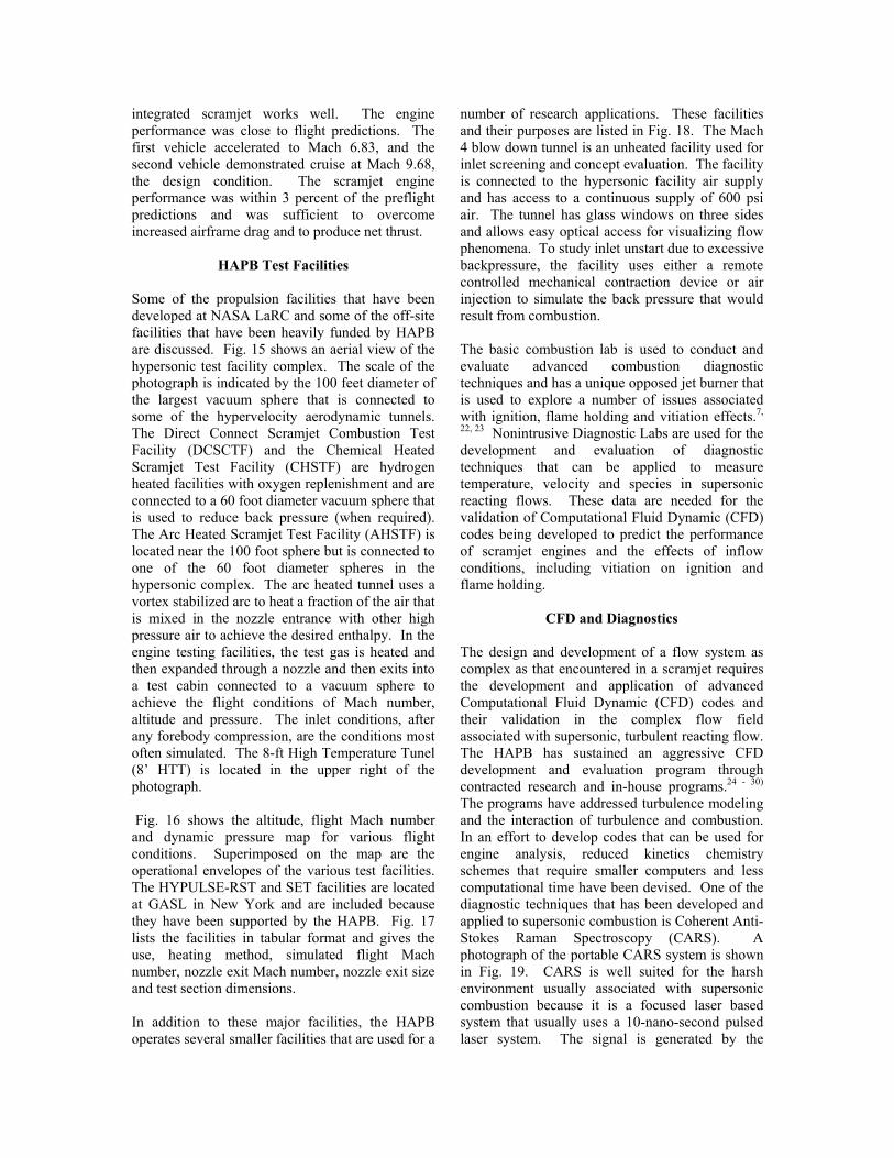
Some of the propulsion facilities that have been developed at NASA LaRC and some of the off-site facilities that have been heavily funded by HAPB are discussed. Fig. 15 shows an aerial view of the hypersonic test facility complex. The scale of the photograph is indicated by the 100 feet diameter of the largest vacuum sphere that is connected to some of the hypervelocity aerodynamic tunnels. The Direct Connect Scramjet Combustion Test Facility (DCSCTF) and the Chemical Heated Scramjet Test Facility (CHSTF) are hydrogen heated facilities with oxygen replenishment and are connected to a 60 foot diameter vacuum sphere that is used to reduce back pressure (when required). The Arc Heated Scramjet Test Facility (AHSTF) is located near the 100 foot sphere but is connected to one of the 60 foot diameter spheres in the hypersonic complex. The arc heated tunnel uses a vortex stabilized arc to heat a fraction of the air that is mixed in the nozzle entrance with other high pressure air to achieve the desired enthalpy. In the engine testing facilities, the test gas is heated and then expanded through a nozzle and then exits into a test cabin connected to a vacuum sphere to achieve the flight conditions of Mach number, altitude and pressure. The inlet conditions, after any forebody compression, are the conditions most often simulated. The 8-ft High Temperature Tunel (8’ HTT) is located in the upper right of the photograph. Fig. 16 shows the altitude, flight Mach number and dynamic pressure map for various flight conditions. Superimposed on the map are the operational envelopes of the various test facilities. The HYPULSE-RST and SET facilities are located at GASL in New York and are included because they have been supported by the HAPB. Fig. 17 lists the facilities in tabular format and gives the use, heating method, simulated flight Mach number, nozzle exit Mach number, nozzle exit size and test section dimensions. In addition to these major facilities, the HAPB operates several smaller facilities that are used for a
number of research applications. These facilities and their purposes are listed in Fig. 18. The Mach 4 blow down tunnel is an unheated facility used for inlet screening and concept evaluation. The facility is connected to the hypersonic facility air supply and has access to a continuous supply of 600 psi air. The tunnel has glass windows on three sides and allows easy optical access for visualizing flow phenomena. To study inlet unstart due to excessive backpressure, the facility uses either a remote controlled mechanical contraction device or air injection to simulate the back pressure that would result from combustion. The basic combustion lab is used to conduct and evaluate advanced combustion diagnostic techniques and has a unique opposed jet burner that is used to explore a number of issues associated with ignition, flame holding and vitiation effects.7,
22, 23 Nonintrusive Diagnostic Labs are used for the development and evaluation of diagnostic techniques that can be applied to measure temperature, velocity and species in supersonic reacting flows. These data are needed for the validation of Computational Fluid Dynamic (CFD) codes being developed to predict the performance of scramjet engines and the effects of inflow conditions, including vitiation on ignition and flame holding.
CFD and Diagnostics
The design and development of a flow system as complex as that encountered in a scramjet requires the development and application of advanced Computational Fluid Dynamic (CFD) codes and their validation in the complex flow field associated with supersonic, turbulent reacting flow. The HAPB has sustained an aggressive CFD development and evaluation program through contracted research and in-house programs.24 - 30) The programs have addressed turbulence modeling and the interaction of turbulence and combustion. In an effort to develop codes that can be used for engine analysis, reduced kinetics chemistry schemes that require smaller computers and less computational time have been devised. One of the diagnostic techniques that has been developed and applied to supersonic combustion is Coherent Anti-Stokes Raman Spectroscopy (CARS). A photograph of the portable CARS system is shown in Fig. 19. CARS is well suited for the harsh environment usually associated with supersonic combustion because it is a focused laser based system that usually uses a 10-nano-second pulsed laser system. The signal is generated by the

interaction of two pump laser beams of different colors interacting in the focal volume to produce a third laser beam that contains the spectral data from which the temperature and species concentration and, in some configurations the velocity vectors, can be derived. The fact that the output signal is also a laser beam helps in rejecting the background light emitted by combustion. The CARS data are derived from the theoretical spectra of the gas being probed. Fig. 20 shows an example of how CARS works. In the figure, the normalized Raman shifted spectra are shown as a function of temperature at 0.28 mole fraction of nitrogen and at 1500 K for nitrogen concentrations from 0.061 to 0.70 mole fraction. From the best fit of the measured signal to the calculated spectra, the concentration and temperature can be derived. Fig. 21 shows a CARS system operating in a laboratory Mach 2 supersonic vitiated air jet that is 10 mm in diameter. The laser beams are visible even in the combusting flow. CARS has been applied to direct connect testing in the DCSCTF using the combustor model shown in Figs. 22(a) and (b). This experiment utilized a direct connected combustor model attached to the vitiated heater simulating Mach 7 flight with a Mach 2.0 nozzle supplying heated test gas to the combustor duct at one atmosphere. This simplified combustor geometry was designed as a CFD code validation experiment. The details of the injector are shown in Fig. 22(b). A Mach 2.5 supersonic hydrogen jet was injected at a 30 degree angle a few step heights downstream of the rearward facing flame holding step. An equivalence ratio based on the duct flow of 1.0 was used. Since the hardware was not water cooled, the test duration was 20 sec. per run. About 3000 CARS samples were taken at each data plane. The duct begins expanding at a 3 degree angle on one wall just down steam of the injector. Data taken at stations 1, 3, 5, 6 and 7 are presented in Fig. 23. The figure compares the CARS temperature data with CFD calculations. Fig. 24 shows a similar data format for the oxygen mole fractions. Although the comparisons are not exact, the figures suggest that a more refined set of data with higher grid density may well be useful in defining the ability of CFD codes in predicting supersonic reacting flow. Also, these data were the composite of a number of 20 second tests where conditions may not be exact. Recently, the CARS system precision has been improved by a factor of 2, and Rayleigh velocimetry capability was added to the system.
Summary The Hypersonic Airbreathing Propulsion Branch at NASA Langley Research Center has maintained an active supersonic combustion ramjet (scramjet) research program for nearly 40 years. The main focus of this program has been the development of the technologies required for application of airbreathing propulsion systems for launch vehicles. Some of the major programs and a few research highlights that enabled the recent successful flight testing of a scramjet powered vehicle at Mach 7 and Mach 10 were included. Since an overview was presented, many of the details involved in the design and development of a scramjet were omitted. The more advanced reader in scramjet propulsion technology is referred to the several references. Some of these references were presented at national meetings and are available from AIAA or other publishers and contain details of the tests and facilities covered.
References
1) Northam, G. Burton & Anderson, G. Y., “Supersonic Combustion Ramjet Research at Langley,” AIAA 24th Aerospace Sciences Meeting, Jan. 1986.
2) Waltrup, Paul P., Anderson, Griffin, Y.,
and Stull, Frank D., “Supersonic Combustion Ramjet (Scramjet) Engine Development in the United States,” Proceedings—3rd International Symposium on Air Breathing Engines, 6, pp. 835-861, 1976.
3) Andrews, Earl, “Scramjet Development
and Testing in the United States,” AIAA-NAL-NASDA-ISAS 10th International Space Planes and Hypersonic Systems and Technologies Conference Committee, AIAA 2001-1927, Kyoto, Japan, April 24-27, 2001.
4) Guy, Robert W., Rogers, R. C., Puster, R.
L., Rock, K. E. and Diskin, G. S., “The Langley Scramjet Test Complex,” AIAA 96-3243, July 1996.

5) Guy, Robert W. and Mackley, Earnest A., “Initial Wind Tunnel Tests at Mach 4 and 7 of a Hydrogen-Burning, Airframe-Integrated Scramjet,” AIAA 79-7045, Presented at the 4th ISABE, Lake Buena Vista, FL, Apr. 1-6, 1979.
6) Beach, H. L., Jr., Mackley, Earnest A.,
Rogers, R. C. and Chinitz, W.: “Use of Silane in Silane Research,” 17Th JANNAF Comb. Meet. Vol. I. CPIA Pub.329, pp. 639-659. Nov. 1980.
7) Pellett, G. L., Northam, G. B. and Wilson,
L. G., “Counterflow Diffusion Flames of Hydrogen, and Hydrogen Plus Methane, Ethane, Propane, and Silane, vs. Air: Strain Rates at Extinction,” 29th Aerospace Sciences Meeting, Reno, NV, Jan. 7-10, 1991.
8) Guy, Robert W. and Mackley, Ernest A.,
“Initial Wind Tunnel Tests at Mach 4 and 7 of a Hydrogen-Burning, Airframe-Integrated Scramjet,” AIAA 79-7045, Presented at 4th International Symposium on Air Breathing Engines, Lake Buena Vista, FL, Apr. 1-6, 1979.
9) Srinivasan, S., McClinton, C. R., and
Kamath, P. S.: “Numerical Simulation of Flow Through the Langley Parametric Scramjet Engine,” SAE 89-2314, Sep. 1989.
10) Anderson, G. Y., Benzce, D. P., and
Sanders, B. W., “Ground Tests Confirms the Promise of Hypersonic Propulsion,” Aerospace America, pp. 38-42, Sep. 1987.
11) Rogers, R. C., Capriotti, D. P., Guy, R.
W., “Experimental Supersonic Combustion Research at NASA Langley,” 20th AIAA Advanced Measurement and Ground Testing Technology Conference, Albuquerque, NM, AIAA-98-2506, June 15, 1998.
12) Voland, Randall T., and Rock, Kenneth E.,
“NASP Concept Demonstration Engine and Subscale Parametric Engine Tests.” AIAA Sixth International Aerospace Planes and Hypersonics Technologies Conference, Chattanooga, TN, AIAA Paper 95-6055, , Apr. 1995.
13) Waldman, B.; Harsha, P., “NASP-A MaturingTechnology Base,” AIAA Paper No. 93-5173.
14) Rausch, V. L., McClinton, C. R., and
Hicks, J. w.: “NASA Scramjet Flights to Breathe New Life into Hypersonics,” Aerospace America, Vol. 35, No. 7, pp. 40-46, July 1997.
15) Rauch, V. L., McClinton, C. R., and
Crawford, J. L., “Hyper-X: Flight Validation of Hypersonic Airbreathing Technology,” ISABE 97-7024, Chattanooga, TN. Sept., 1997.
16) Bogar, T. J., Alberico, J. F., Johnson, D.
B., Eapinoss, A. M., and Lockwood, M. K.: “Dual-Fuel Lifting BodyConfiguration Development,” AIAA-96-4592, Nov. 1996.
17. Voland, R. T., Rock, K. E., Huebner, L.
D., Witte, D.W., Fischer, K. E., and McClinton, C. R., “Hyper-X Engine Design and Ground Test Program,” AIAA-98-1532, Apr. 1998.
18 . McClinton, C. R., Holland, S. D., Rock,
K. E., Engelund, W. C., Voland, R. T., Huebner, L. D., and Rogers, . C., “Hyper-X Wind Tunnel Program,” 36th AIAA Aerospace Sciences Meeting and Exhibit, Jan. 1998, Reno, NV AIAA-98-0553.
19 . McClinton, C. R., Voland, R. T., Holland,
S. D., and Engelund, W. C., “Wind Tunnel Testing, Flight Scaling and Flight Validation with Hyper-X,” 20th AIAA Advanced Measurements and Ground Testing Technology Conference, June 1998, AIAA-98-2866.
20. Huebner, L. D., Rock, K. E., Witte, D. W.,
Ruf, E. G., Andrews, E. H., “Hyper-X Engine Testing in the NASA 8-FT High Temperature Tunnel,” AIAA/ASME/SAE/ ASEE 36th Joint Propulsion Conference, Huntsville, AL, July 17-19, 2000, AIAA Paper 2000-3605.
21. . Huebner, L. D., Rock, K. E., Ruf, E. G.,
Witte, D. W., Andrews, E. H., “Hyper-X Ground Testing for X-43 Flight Risk Reduction,” AIAA/NAL-NASDA-ISAS

10th International Space Planes and Hypersonic Systems and Technologies Conference, Kyoto, Japan, April 24-27, 2001. AIAA Paper 2001-1809.
22. Pellett, G. L., Bruno, Claudio, and Chenitz,
W. “Review of Air Vitiation Effects on Scramnjet Ignition and Flameholding Combustion Processes,” 38th AIAA/ASME/SAE/ASEE Joint Propulsion Conference and Exibit, Indianapolis, IN, 7-10 July, 2002, AIAA Paper 2002-3880.
23. Drummond, J.P., Danehy, P.M., Bivolaru,
D., Gaffney, R.L., Parker, P., Chelliah, H.K., Cutler, A.D., Givi, P., Hassan, H.A., “Predicting the Effects of Test Media in Ground-Based Propulsion Testing,” 2006 Annual ITEA Technology Review, Cambridge, MA, August 7–10, 2006.
24. Bivolaru, D, Danehy, P.M., Grinstead,
K.D., Jr., Tedder, S., and Cutler, A.D., “Simultaneous CARS and Interferometric Rayleigh Scattering,” AIAA-2006-2968, 25th AIAA Aerodynamic Measurement Technology and Ground Testing Conference, San Francisco, CA, June 5 - 8, 2006.
25. Bivolaru, D., Danehy, P.M., Lee, J.W.,
Gaffney, R.L., Cutler, A.D., “Single-pulse, Multi-point Multi-component Interferometric Rayleigh Scattering Velocimeter,” AIAA-2006-836, 44th AIAA Aerospace Sciences Meeting, Reno, NV, 9-12 Jan., 2006.
26. Rodriguez, C.G. and Cutler, A.D., “Computational Simulation of a Supersonic- Combustion Benchmark Experiment,” AIAA-2005-4424, 41st AIAA/ASME/SAE/ASEE Joint Propulsion Conference & Exhibit, Tucson, AZ, July 10-13, 2005.
27. Tedder, S. A., O’Byrne, S., Danehy, P.
M., Cutler, A. D., “CARS Temperature and Species Concentration Measurements in a Supersonic Combustor with Normal Injection,” AIAA Paper 2005-0616, 43rd AIAA Aerospace Sciences Meeting, Reno, NV, Jan 10-13, 2005.
28. Cutler, A.D., Danehy, P.M., O’Byrne, S.,
Rodriguez, C.G., Drummond, J.P., “Supersonic Combustion Experiments for CFD Model Development and Validation (Invited),” AIAA Paper 2004-0266, 42nd Aerospace Sciences Meeting, Reno, NV, Jan. 5-8, 2004.
29. O’Byrne, S., Danehy, P.M., Cutler, A.D., “Dual-Pump CARS Thermometry and Species Concentration Measurements in a Supersonic Combustor,” AIAA Paper 2004-0710, 42nd Aerospace Sciences Meeting, Reno, NV, Jan. 5-8, 2004.
30. Rodriguez, C.G. and Cutler, A.D., “CFD
Analysis of the SCHOLAR Scramjet Model,” AIAA Paper 2003-7039, AIAA 12th International Space Planes & Hypersonic Systems & Technologies Conference, Norfolk, VA, 15-19 Dec. 2003.

Fig. 1 Time line of technology development at NASA-LaRC Hypersonic
Airbreathing Propulsion Branch over the last 40 years
Fig. 2. HRE Structure Assembly Model Fig. 3 HRE Aerothermo Model
1965 to 1975

Fig. 4 Niclel 3-Strut scramjet in the CHSTF for Mach 4 testing 1978 to 1988

Fig. 5 Copper 3-Strut scramjet in AHST for Mach 7 testing 1978 to 1988
Fig. 6 NASP government baseline engine testing in the CHST at Mach 4
Fig. 7 NASP Contractor Demonstration Engine before testing in 8-ft. HTT 1985 to 1995

Fig. 8 The Hyper-X launch vehicle stack
Fig. 9 Hyper-X Key mission events March 27, 2004 Mach 6.83 Nov. 16, 2004 Mach 9.68
Hyper-X Launch Vehicle Booster, Pegasus
AdapterB-52B
Hyper X Research Vehicle

Fig. 10 Hyper-X, X-43A mission flight path and mission detail
Fig. 11 Hyper-X engine models being testing in various facilities
HXFE/VFS in LaRC 8-Ft HXEM/FFS in LaRC 8-Ft
HXEM in LaRC AHSTF HSM in HYPULSE at GASL

Fig. 12 Flight vs wind tunnel pressure distribution with and without fuel
Fig. 13 Technical challenges addressed during Hyper-X program
Forebody and Lee Side Boundary Layer (BL) transition BL Trips Sharp leading edge structure FADS Thermal load Flight scaling Shear drag Wall temperature history
Systems/Packaging Scale! Antenna interference Captive carry man-rated Stiffness Weight vs. scale vs. accelerationAcceleration
Wings and Tails Sizing Scale effects on trim Thermal stresses/growthGap and corner flows Shock impingement
Inlet Starting mechanism Starting pitch moment Cowl closed heating – Trips – Gap leakage – Seals – Corner flows Performance – Drag – Mass capture – On – Off design Sidewall length 3-D spillage Cowl leading edge heating
Isolator Facility effectAspect ratio
Combustor Small fuel injector survival Combustor reaction rates Thermal loads Test condition uncertainty – AOA and Yaw effects – Dynamic press, and Mach Fuel control laws Facility effects on ignition, flameholding and comb. pres.
Nozzle Nozzle lift and pitch moment Trim drag BL relaminarization Propulsion-airframe interaction
Axial Station
P r e s s u r e
Wind tunnel – no fuel Wind tunnel – with fuel Flight – no fuel Flight –with fuel
Pressure

Fig. 14 Hyper-X program demonstrated propulsive efficiency
required for future applications
Fig. 15 NASA-LaRC hypersonic test facility complex
Turbojets
Scramjets
Ramjets
0 10 20
MACH NUMBER
Isp
Rockets
X-43 scaled
Airframe Integrated

Fig. 16 Flight regime covered various test facilities
Fig. 17 Major facility characteristics

Fig. 18 Other NASA-LaRC facilities and their applications
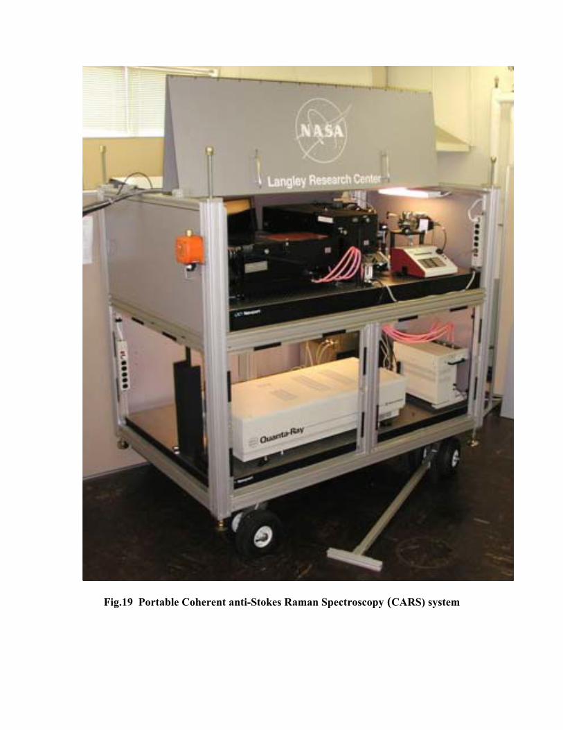
Fig.19 Portable Coherent anti-Stokes Raman Spectroscopy (CARS) system

Fig. 20 How CARS works
Fig. 21 Application of CARS in a laboratory supersonic vitiated air jet (10 mm dia.)
M e x it= 2 v i t ia te d a i r je tC A R S - R a y le ig h b e a m s M e x it= 2 v i t ia te d a i r je tC A R S - R a y le ig h b e a m s
Effect of N2 concentration
Effect of temperature
• CARS spectra are best fit to a library of theoretical spectra
Coherent anti-Stokes Raman Spectroscopy

Fig. 22 Application of CARS to supersonic combustion and model validation (a) over all duct, (b) injector details

Fig. 23 Comparison of CARS temperature profiles with CFD calculations

Fig. 24 Comparison of CARS O2 profiles with CFD calculations 3