AN OVERVIEW OF AIRCRAFT MECHANICS AND STRUCTURES
13
25 TH INTERNATIONAL CONGRESS OF THE AERONAUTICAL SCIENCES © BAE SYSTEMS, 2006. Published by ICAS with permission. 1 Abstract This paper gives an introduction to the aircraft engineering disciplines that can be regarded as belonging to ‘Mechanics and Structures’. For the purposes of this paper this covers Design Engineering, Materials, Structures, Structural and Dynamic Test, Aerodynamics, Wind Tunnels, Flight Systems, Flight Simulation and Flight Test. For each of these disciplines, a description of the main activities is provided, together with the basic principles and methods that are used. This includes the development, testing and validation of the theoretical design models, and their use for the qualification and certification of aircraft and their systems. The paper includes a comprehensive biography of some key references that are used by practicing engineers to carry out their work. 1 Introduction Mechanics and Structures is one of six corporate disciplines within BAE Systems, the others being Systems Engineering, Software Engineering, Electrical and Electronics Engineering, Manufacturing Engineering and Support Engineering. At this level, the disciplines are very broad, in order to cover land, sea and air vehicles. The Mechanics and Structures Discipline includes the traditional engineering disciplines, such as Aerodynamics, Hydrodynamics, Structures, Materials and Flight Systems – which can all be further sub- divided into their specialist areas. The aim of this paper is to provide an overview of the work carried out on aircraft within the Mechanics and Structures Discipline in order to introduce the subject and to generate greater interest – to expand the knowledge of those already involved in aircraft development and to attract new engineers into the profession. Fig. 1. Multi-disciplinary design Although the information is presented from a military aircraft perspective, many of the fundamental principles, processes and technologies that are used for design are common to civil aircraft. The design of any modern aircraft is a complex multi-disciplinary activity where detailed planning, good technical skills and a high level of systems integration are necessary. The design is progressively refined from initial concept through to detailed design, using all the engineering disciplines described below. The specialist areas that are needed to establish a ‘flying platform’ are indicated in Fig. 1 and are supplemented by those for the aircraft’s avionic systems – and, for a military aircraft, its weapon systems. AN OVERVIEW OF AIRCRAFT MECHANICS AND STRUCTURES Chris Fielding BAE Systems Keywords: Aerodynamics, Airframe, Structures, Flight Systems, Testing
Transcript of AN OVERVIEW OF AIRCRAFT MECHANICS AND STRUCTURES
25TH INTERNATIONAL CONGRESS OF THE AERONAUTICAL SCIENCES
© BAE SYSTEMS, 2006. Published by ICAS with permission. 1
Abstract
This paper gives an introduction to the aircraft engineering disciplines that can be regarded as belonging to ‘Mechanics and Structures’. For the purposes of this paper this covers Design Engineering, Materials, Structures, Structural and Dynamic Test, Aerodynamics, Wind Tunnels, Flight Systems, Flight Simulation and Flight Test. For each of these disciplines, a description of the main activities is provided, together with the basic principles and methods that are used. This includes the development, testing and validation of the theoretical design models, and their use for the qualification and certification of aircraft and their systems. The paper includes a comprehensive biography of some key references that are used by practicing engineers to carry out their work.
1 Introduction Mechanics and Structures is one of six corporate disciplines within BAE Systems, the others being Systems Engineering, Software Engineering, Electrical and Electronics Engineering, Manufacturing Engineering and Support Engineering. At this level, the disciplines are very broad, in order to cover land, sea and air vehicles. The Mechanics and Structures Discipline includes the traditional engineering disciplines, such as Aerodynamics, Hydrodynamics, Structures, Materials and Flight Systems – which can all be further sub-divided into their specialist areas.
The aim of this paper is to provide an overview of the work carried out on aircraft within the Mechanics and Structures Discipline in order to introduce the subject and to generate greater interest – to expand the knowledge of those already involved in aircraft development and to attract new engineers into the profession.
Fig. 1. Multi-disciplinary design Although the information is presented from a military aircraft perspective, many of the fundamental principles, processes and technologies that are used for design are common to civil aircraft. The design of any modern aircraft is a complex multi-disciplinary activity where detailed planning, good technical skills and a high level of systems integration are necessary. The design is progressively refined from initial concept through to detailed design, using all the engineering disciplines described below. The specialist areas that are needed to establish a ‘flying platform’ are indicated in Fig. 1 and are supplemented by those for the aircraft’s avionic systems – and, for a military aircraft, its weapon systems.
AN OVERVIEW OF AIRCRAFT MECHANICS AND STRUCTURES
Chris Fielding BAE Systems
Keywords: Aerodynamics, Airframe, Structures, Flight Systems, Testing

CHRIS FIELDING
2
2 Aerodynamics and Wind Tunnels Aerodynamics and Wind Tunnels are closely related engineering disciplines that work together to establish the aircraft’s external shape. This includes the design and optimisation of the aircraft configuration and its flying qualities, in order to provide satisfactory aircraft handling and performance.
Fig. 2. Wind tunnel facilities Wind tunnels are used to measure the forces and moments acting on the vehicle, due to the motion of the air passing over its surface. The model is mounted on a sensitive and accurately calibrated measurement balance. The measured information, together with data from semi-empirical estimation methods and computational fluid dynamics, is used to produce an aerodynamic dataset. This is part of the mathematical modelling of the vehicle, which enables prediction of its flight characteristics. Scale models of aircraft are used in a range of instrumented test facilities. A low-speed wind tunnel is used for subsonic testing, with Mach numbers typically being less than 0.5. Above this Mach number, a high-speed tunnel is used for transonic and supersonic testing. Fig. 2 shows (A) model design and manufacture, (B) low speed testing, (C) high speed testing, and (D) specialised jet-effects facilities for vertical/short take-off and landing aircraft. Some further wind tunnel examples are shown in Fig. 3: (A) Manufacture and assembly of a
precision model for testing in a high-speed wind tunnel. Traditional methods of model manufacture are now complemented by modern techniques such as stereo-lithography; (B) Water tunnel testing can be used to visualise the flow around an airframe. In wind tunnels, smoke can be used to visualise the airflow; (C) For aircraft spin testing, a vertical wind tunnel is used. This enables spin behaviour to be understood, and recovery techniques to be established; (D) A hot-gas laboratory is used to assess the potentially destructive effects that hot engine exhaust gases can have on the surface of a runway or a ship’s deck; (E) A hot-gas ingestion model is used to assess intake ingestion effects, for a short take-off and vertical landing (STOVL) aircraft; (F) An inlet effects model is used for measuring the loads on the airframe due to the inlet flow.
Fig. 3. Wind tunnel testing Aerodynamicists are traditionally responsible for the definition of the aircraft configuration in terms of its shape, performance, stability and control. The design of the configuration includes wing design, fin and tail design and the

3
AN OVERVIEW OF AIRCRAFT MECHANICS AND STRUCTURES
shaping of all external parts of the vehicle, in order to meet design targets. These now include stealth requirements for combat aircraft and Fig. 4(A) shows ground-based testing to measure radar cross-section. The aerodynamic design includes propulsion integration, whereby the aircraft fore-bodies, intakes and after-bodies are designed to produce optimum installed engine performance. Performance prediction tools are used for the preparation of operating data manuals for aircraft customers – an extract from which is shown in Fig. 4(B). Computational fluid dynamics (CFD) is used for the modelling and theoretical prediction of the flow around specified geometry, to predict external pressure distributions, as shown in Fig. 4(C). Such data is used in support of wind tunnels and flight testing, to provide aerodynamic data for aircraft design and qualification. With improvements in information technology and methods, the growing trend is for increased use of CFD. This trend is also being driven by the high costs associated with flight testing and wind tunnels. CFD can also be used for inverse design, whereby the designer specifies the pressure distribution and the CFD method then determines the shape that produces that pressure distribution.
Fig. 4. Configuration aerodynamics Aerostructures is a sub-discipline which covers the aerodynamic loading and aero-servo-elastic aspects of the airframe, including static and dynamic loading, flutter, airframe/flight control system structural coupling, the carriage and release of aircraft stores, and acoustics. As its name implies, aerostructures primarily involves those aspects of aerodynamics that impact on
the structural strength and stiffness of an airframe. Thus, for example, acoustics can be a major source of fatigue damage and work is carried out to predict and measure the noise field, on and around an aircraft. Fig. 5(A) shows preparation for thermo-acoustic testing of a powered scale aircraft model in an anechoic chamber. The results are used in the structural design process. The static loading of the airframe due to steady aerodynamic loads, and the dynamic loading due to effects such as buffeting, store release, and landing, are predicted from mathematical models. The safe carriage/release/firing/jettison of stores has to be demonstrated through experimental and theoretical methods. Twin-sting rigs are used for testing stores separation in the wind tunnel. Fig. 5(B) shows a simulated missile release. Aircraft flutter arises due to the interaction of the elastic, inertial and unsteady aerodynamic forces. Aircraft are designed to be free from flutter within the required flight envelope, since it is potentially catastrophically destructive. Structural coupling is closely related to flutter and is due to the interaction of the aircraft’s aero-elastic modes with the flight control system. Fig. 5(C) shows ground testing, with the aircraft mounted on air springs. Ground vibration testing is used to determine the aircraft structural mode characteristics, and structural coupling testing provides the information needed to enable filters to be designed for suppressing the structural frequencies within the flight control system.
Fig. 5. Aero-structures
CHRIS FIELDING
4
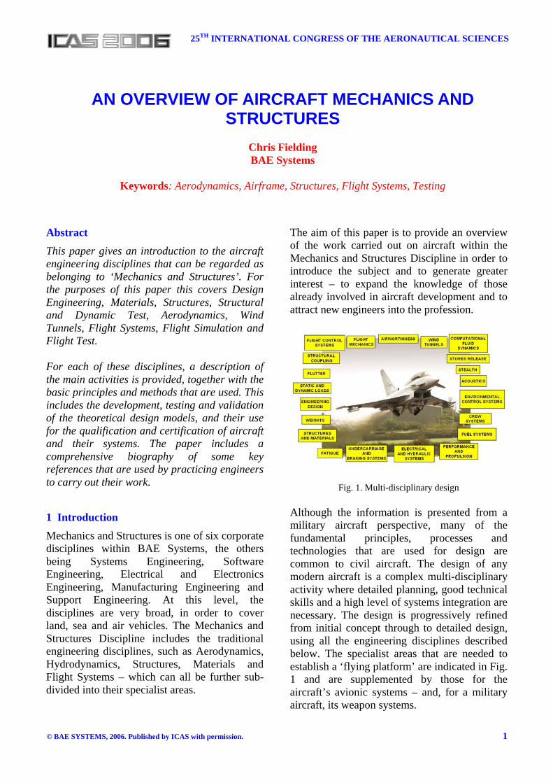
Flight dynamics is another sub-discipline which is mainly concerned with providing satisfactory aircraft stability, control and handling, and includes flight mechanics, flight control laws design and, aircraft simulation and handling assessment. Flight control laws design (Fig. 6(A)) involves the definition of feedback filtering, command path filtering and gain schedules, to provide satisfactory aircraft stability augmentation and handling characteristics. Simulation involves the modelling of the aircraft and its systems to evaluate its performance, stability and handling (Fig. 6(B)). Flight mechanics covers the evaluation of the stability and control of vehicles and the definition of an aerodynamic dataset for flight control laws design, flight simulation and the prediction of aircraft handling qualities. Aircraft handling is ultimately assessed in flight (Fig. 6(C)), where the data gathered is used to validate the aerodynamic dataset, by using parameter identification techniques.
Fig.6. Flight Dynamics
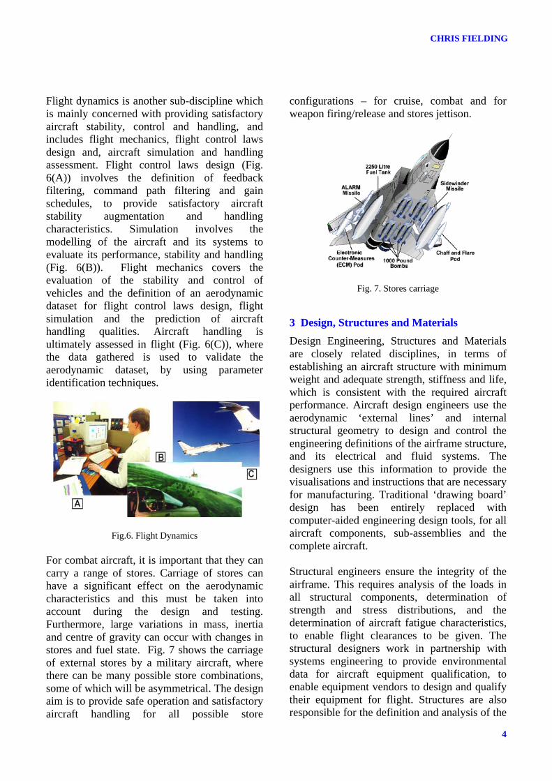
For combat aircraft, it is important that they can carry a range of stores. Carriage of stores can have a significant effect on the aerodynamic characteristics and this must be taken into account during the design and testing. Furthermore, large variations in mass, inertia and centre of gravity can occur with changes in stores and fuel state. Fig. 7 shows the carriage of external stores by a military aircraft, where there can be many possible store combinations, some of which will be asymmetrical. The design aim is to provide safe operation and satisfactory aircraft handling for all possible store
configurations – for cruise, combat and for weapon firing/release and stores jettison.
Fig. 7. Stores carriage
3 Design, Structures and Materials Design Engineering, Structures and Materials are closely related disciplines, in terms of establishing an aircraft structure with minimum weight and adequate strength, stiffness and life, which is consistent with the required aircraft performance. Aircraft design engineers use the aerodynamic ‘external lines’ and internal structural geometry to design and control the engineering definitions of the airframe structure, and its electrical and fluid systems. The designers use this information to provide the visualisations and instructions that are necessary for manufacturing. Traditional ‘drawing board’ design has been entirely replaced with computer-aided engineering design tools, for all aircraft components, sub-assemblies and the complete aircraft. Structural engineers ensure the integrity of the airframe. This requires analysis of the loads in all structural components, determination of strength and stress distributions, and the determination of aircraft fatigue characteristics, to enable flight clearances to be given. The structural designers work in partnership with systems engineering to provide environmental data for aircraft equipment qualification, to enable equipment vendors to design and qualify their equipment for flight. Structures are also responsible for the definition and analysis of the

5
AN OVERVIEW OF AIRCRAFT MECHANICS AND STRUCTURES
major airframe static and fatigue tests, analysis of results from flight testing and for ‘check stress’ analysis (an audit of the structural design).
Fig. 8. Evolution of materials usage Materials engineers are responsible for the testing and qualification of materials used in the airframe and for ensuring that the manufactured and assembled components meet the design requirements. This involves a wide range of activities from establishing design and acceptance standards for new materials or manufacturing processes, generating appropriate control documentation such as material and process specifications, ensuring that procedures and processes are properly utilised and offering a technical service to engineering, manufacturing and the end customer (e.g. defect investigations). Fig. 8 shows how the choice of materials has varied since 1930. The use of wood and steel has diminished, with an associated increase in the use of titanium and composite materials, with the use of composites continuing to increase.
Fig. 9. Properties of materials
The advantages and disadvantages of the main materials used are listed in Fig. 9. The ideal material would have high strength or stiffness, low weight, be durable, easily processed and environmentally friendly, including the use of harmless and environmentally friendly substances during processing. In reality, the choice of materials or combinations of materials is a compromise. Materials are tested and analysed, to determine their characteristics and establish the best fit to the intended application.
Fig. 10. Computer-aided design Computer-aided design of components has become the norm, as shown by the example in Fig. 10. This provides risk reduction in manufacturing, by enabling complex assemblies to be designed and assembled in a virtual environment. The picture in Fig 10 (left) shows a cockpit display structure; in Fig 10 (right), it has had its equipment and associated electrical system fitted. This technology has replaced the need for a full-size physical mock-up, leading to cost reductions and allowing confidence in the design to be gained at an earlier stage in the life cycle.
Fig. 11. Airframe loading
CHRIS FIELDING
6
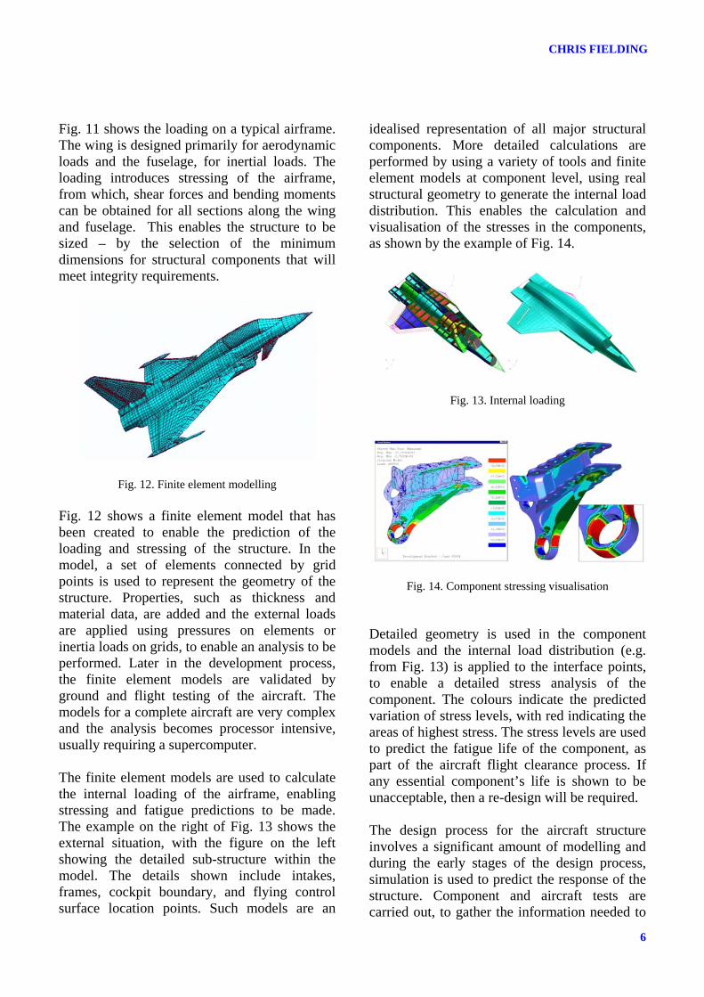
Fig. 11 shows the loading on a typical airframe. The wing is designed primarily for aerodynamic loads and the fuselage, for inertial loads. The loading introduces stressing of the airframe, from which, shear forces and bending moments can be obtained for all sections along the wing and fuselage. This enables the structure to be sized – by the selection of the minimum dimensions for structural components that will meet integrity requirements.
Fig. 12. Finite element modelling Fig. 12 shows a finite element model that has been created to enable the prediction of the loading and stressing of the structure. In the model, a set of elements connected by grid points is used to represent the geometry of the structure. Properties, such as thickness and material data, are added and the external loads are applied using pressures on elements or inertia loads on grids, to enable an analysis to be performed. Later in the development process, the finite element models are validated by ground and flight testing of the aircraft. The models for a complete aircraft are very complex and the analysis becomes processor intensive, usually requiring a supercomputer. The finite element models are used to calculate the internal loading of the airframe, enabling stressing and fatigue predictions to be made. The example on the right of Fig. 13 shows the external situation, with the figure on the left showing the detailed sub-structure within the model. The details shown include intakes, frames, cockpit boundary, and flying control surface location points. Such models are an
idealised representation of all major structural components. More detailed calculations are performed by using a variety of tools and finite element models at component level, using real structural geometry to generate the internal load distribution. This enables the calculation and visualisation of the stresses in the components, as shown by the example of Fig. 14.
Fig. 13. Internal loading
Fig. 14. Component stressing visualisation Detailed geometry is used in the component models and the internal load distribution (e.g. from Fig. 13) is applied to the interface points, to enable a detailed stress analysis of the component. The colours indicate the predicted variation of stress levels, with red indicating the areas of highest stress. The stress levels are used to predict the fatigue life of the component, as part of the aircraft flight clearance process. If any essential component’s life is shown to be unacceptable, then a re-design will be required. The design process for the aircraft structure involves a significant amount of modelling and during the early stages of the design process, simulation is used to predict the response of the structure. Component and aircraft tests are carried out, to gather the information needed to

7
AN OVERVIEW OF AIRCRAFT MECHANICS AND STRUCTURES
validate the models used for the design. Fig. 15 shows some examples: (A) This is taken from an animation of a dynamic situation, where the stresses in a component are varying with time, following an impulsive disturbance (such as an aircraft missile firing). The stresses will reduce as the response decays due to damping.
Fig. 15. Structures modelling and testing
(B) During fatigue testing, servo-controlled hydraulic actuators are used to excite the structure. Accelerometers are mounted on the structure to monitor the structural response – for data recording to enable calculation of the measured fatigue spectrum. The information is used for update and validation of the theoretical models. (C) During ground testing the aircraft is supported by air-springs and is excited via the structure for ground resonance tests, or via its flying control surfaces for airframe/flight control system ‘structural coupling’ tests. The ground resonance testing is used to identify the structural modes in order to validate the structural models used for the design. The structural coupling testing is to enable the design of structural mode filters for the flight control system’s feedback signals. (D) The ground tests do not include the effects of aerodynamic forces and moments on the
structure. These are predicted by modelling and are used to extrapolate the ground test results, to give the best possible estimation of in-flight characteristics. As the ultimate test, the structural modes are deliberately excited during flight, to validate the complete aero-servo-elastic model. Purpose-built rigs are used to perform airframe static tests and fatigue tests, to demonstrate the structural integrity of the complete aircraft, as shown in Fig. 16. For the static tests, the airframe is loaded up to its ‘proof loading’ to show that no permanent deformation occurs. It is then loaded up to its ‘ultimate load’ to show that it does not break. The test information is used to update and validate the models used for the structural design.
Fig. 16. Airframe structural tests During the fatigue testing, the airframe is subjected to a loading spectrum which is representative of what the vehicle will experience during its service life. The structure is tested to destruction, so that a safe life can be specified. A safety factor is added, to ensure that the safe life takes account of all material and manufacturing variations. Other airframe structural testing carried out includes the dynamic loading through impact, such as bird strike, and the acoustic loading by testing in an acoustic fatigue facility.

CHRIS FIELDING
8
4 Flight Systems The Flight Systems Discipline involves the development and qualification of all the systems that are needed to fly an aircraft. Flight systems are essential for safe operation of aircraft and are designed for high integrity. Most of the systems are safety-critical and the aircraft might be lost if any one of the systems completely fails. The systems are usually integrated to form a ‘vehicle management system’, to provide synergy and optimum performance. The integration includes the other avionics systems that are needed to complete the aircraft’s mission (e.g. navigation and cockpit displays). The propulsion system is used to provide thrust and is the primary source of hydraulic, electrical and pneumatic power. The power generated is used by the avionic systems, cockpit displays, radar, weapons systems, flight control system, undercarriage, environmental control system, fuel system and crew support systems. Civil aircraft also require power for services, galley, lighting and cabin pressurisation, to provide a comfortable environment for their passengers.
Fig. 17. Fuel systems The fuel system usually has wing and fuselage tanks, with the system status being displayed in the cockpit, as indicated in Fig. 17(A). The fuel system must operate for the ‘g’ range of the aircraft, including flight at negative g − and inverted flight, for combat aircraft. The tanks
are sized to meet the aircraft’s mission requirements, with long range usually requiring large capacity. Military aircraft might be fitted with external wing tanks for extended range and/or mission time, with some military aircraft being re-fuelled during flight by a tanker aircraft. The aircraft fuel system is integrated with the design of the propulsion system, which is designed to meet aircraft performance and integrity requirements. As part of the ‘virtual aircraft assembly’ described in Section 3, it is possible to check the installation of the engine in the airframe, as shown in Fig. 17(B). The propulsion system is tested by its manufacturer using an engine test stand as shown in Fig. 17(C), prior to installation and testing in the airframe.
Fig. 18. Environmental control systems In flight, it is necessary to remove excessive heat from electronic equipment to maintain acceptable operating conditions. An aircraft’s environmental control system is designed to provide suitable operating conditions to support people and equipment. The system is tested (Fig. 18 (left)) to ensure that it provides effective control of the environment for reliable operation of the avionics equipment and for the support of aircrew − and passengers, for a civil aircraft. The climate in which the aircraft might operate can vary significantly. It must, therefore, be tested to demonstrate operation in extreme conditions. Natural hot and cold testing can be supplemented with an environmental hangar test facility (Fig. 18 (right)) to demonstrate operation in high temperature, high humidity conditions or in extreme cold conditions.
9
AN OVERVIEW OF AIRCRAFT MECHANICS AND STRUCTURES
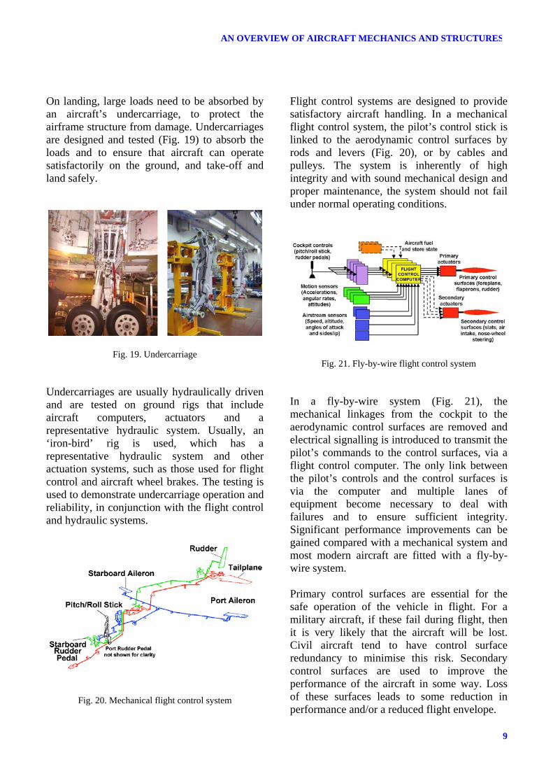
On landing, large loads need to be absorbed by an aircraft’s undercarriage, to protect the airframe structure from damage. Undercarriages are designed and tested (Fig. 19) to absorb the loads and to ensure that aircraft can operate satisfactorily on the ground, and take-off and land safely.
Fig. 19. Undercarriage Undercarriages are usually hydraulically driven and are tested on ground rigs that include aircraft computers, actuators and a representative hydraulic system. Usually, an ‘iron-bird’ rig is used, which has a representative hydraulic system and other actuation systems, such as those used for flight control and aircraft wheel brakes. The testing is used to demonstrate undercarriage operation and reliability, in conjunction with the flight control and hydraulic systems.
Fig. 20. Mechanical flight control system
Flight control systems are designed to provide satisfactory aircraft handling. In a mechanical flight control system, the pilot’s control stick is linked to the aerodynamic control surfaces by rods and levers (Fig. 20), or by cables and pulleys. The system is inherently of high integrity and with sound mechanical design and proper maintenance, the system should not fail under normal operating conditions.
Fig. 21. Fly-by-wire flight control system In a fly-by-wire system (Fig. 21), the mechanical linkages from the cockpit to the aerodynamic control surfaces are removed and electrical signalling is introduced to transmit the pilot’s commands to the control surfaces, via a flight control computer. The only link between the pilot’s controls and the control surfaces is via the computer and multiple lanes of equipment become necessary to deal with failures and to ensure sufficient integrity. Significant performance improvements can be gained compared with a mechanical system and most modern aircraft are fitted with a fly-by-wire system. Primary control surfaces are essential for the safe operation of the vehicle in flight. For a military aircraft, if these fail during flight, then it is very likely that the aircraft will be lost. Civil aircraft tend to have control surface redundancy to minimise this risk. Secondary control surfaces are used to improve the performance of the aircraft in some way. Loss of these surfaces leads to some reduction in performance and/or a reduced flight envelope.
CHRIS FIELDING
10
Crew escape systems (Fig. 22) are designed and tested to provide the safest trajectory, after pilot ejection. The ejection system is designed to be largely independent of the other aircraft systems and must be able to operate, even if other systems have failed. Other pilot support systems provide oxygen, biological and chemical filtration, and crew comfort − providing tolerance to high g. For military combat aircraft, ‘high g’ means pulling 8 or 9 g and a ‘g suit’ is used to help to prevent pilot blackout.
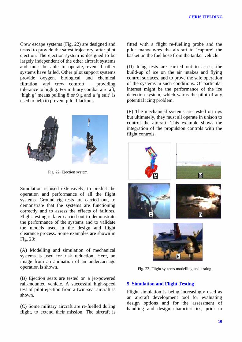
Fig. 22. Ejection system Simulation is used extensively, to predict the operation and performance of all the flight systems. Ground rig tests are carried out, to demonstrate that the systems are functioning correctly and to assess the effects of failures. Flight testing is later carried out to demonstrate the performance of the systems and to validate the models used in the design and flight clearance process. Some examples are shown in Fig. 23: (A) Modelling and simulation of mechanical systems is used for risk reduction. Here, an image from an animation of an undercarriage operation is shown. (B) Ejection seats are tested on a jet-powered rail-mounted vehicle. A successful high-speed test of pilot ejection from a twin-seat aircraft is shown. (C) Some military aircraft are re-fuelled during flight, to extend their mission. The aircraft is
fitted with a flight re-fuelling probe and the pilot manoeuvres the aircraft to ‘capture’ the basket on the fuel hose from the tanker vehicle. (D) Icing tests are carried out to assess the build-up of ice on the air intakes and flying control surfaces, and to prove the safe operation of the systems in such conditions. Of particular interest might be the performance of the ice detection system, which warns the pilot of any potential icing problem. (E) The mechanical systems are tested on rigs but ultimately, they must all operate in unison to control the aircraft. This example shows the integration of the propulsion controls with the flight controls.
Fig. 23. Flight systems modelling and testing
5 Simulation and Flight Testing Flight simulation is being increasingly used as an aircraft development tool for evaluating design options and for the assessment of handling and design characteristics, prior to

11
AN OVERVIEW OF AIRCRAFT MECHANICS AND STRUCTURES
flight. It provides an opportunity for the pilots to familiarise themselves with the aircraft and allows operational effectiveness to be evaluated in a safe environment. The results from piloted simulation play an important part in decision making and provide supporting evidence for the flight clearance process. Flight testing is the ultimate proof of the aircraft and its integrated systems, and all reasonable precautions are taken to ensure flight safety. The testing is used to gather information and to demonstrate the aircraft’s overall performance and effectiveness in a realistic operating environment. The testing exposes the aircraft to the range of external influences that cannot always be effectively modelled or simulated on the ground. Effects such as those due to the aircraft’s aerodynamics need to be proven, and flight testing has to be carried out to completely validate the aircraft. The information gathered from the testing is used for the validation of all the models that were used to design the aircraft and its systems. Finally, the information is used to demonstrate compliance with customer requirements, completing the design process by providing validation of the aircraft in its operating environment. Fig. 24 shows some examples of piloted simulation and flight testing: (A) Piloted simulation of a short take-off and vertical landing (STOVL) aircraft in the hover. Outside-world displays are used to provide good visual cues. A moving-base is used to provide realistic motion cues. (B) Combat simulation is used to assess the effectiveness of aircraft and their weapon systems in realistic combat situations. High resolution and low latency of the outside-word display are needed for good fidelity. (C) Spin testing is carried out to determine an aircraft’s spin characteristics and its ability to
recover. Piloting recovery technique can be assessed and developed. (D) In this example of spin testing, the aircraft is tumbling through space. A significant loss in altitude can occur during a spin and this can result in aircraft loss, especially at low altitudes.
Fig. 24. Flight simulation and flight testing (E) Flight testing involves testing automatic systems that prevent spinning as well as all the other systems on the aircraft - including all of those described in this paper. Other systems that are to be tested and proven include radar, navigation, communications, cockpit displays, maintenance and support systems, and weapons systems (for military aircraft).
6 Closing Remarks This paper has only managed to give a basic introduction to the mechanical and structural aspects of aircraft design. Each of the technical areas described is a specialist topic with its own

CHRIS FIELDING
12
technologies, processes and standards, all of which are underpinned by a wealth of project experience. Much of this information is available and some of it can be found in the references listed in biography, which will lead to the next level of detail.
Acknowledgements The author would like to thank the following people in BAE Systems for reviewing this paper: Jim Banks, Richard Blockley, Brian Cleator, Dave Common, Mike Crompton, Tony Cross, Peter Gates, Neil Graham, Brian Oldfield, Dennis Morley, Allan Seabridge, Terry Smith, Mike Southworth, John Thompson and Brian Weller. Thanks are also due to EADS, Martin Baker, Lockheed Martin, Messier-Dowty and, Pratt & Whitney for giving permission for the use of their photographic material in this paper.
Bibliography
Aerodynamics and Wind Tunnels [1] Cook, M.V. Flight Dynamics Principles. Arnold Publishing, 1997, ISBN 0 470 23590 X. [2] Raymer D.P. Aircraft Design: A Conceptual Approach. AIAA Education Series, 1999, ISBN 1 56347 281 3. [3] Eshelby, M.E. Aircraft Performance: Theory and Practice. Butterworth-Heinmann, 2000, ISBN 1 56347 398 4. [4] Etlin, B. Dynamics of Atmospheric Flight. John Wiley & Sons, 1972, ISBN 0 47124 620 4. [5] Pamadi, B.N. Performance, Stability, Dynamics and Control. AIAA Education Series, 2004, ISBN 1 56347 222 8. [6] Hoerner, S.F. Fluid-Dynamic Drag. Hoerner Fluid Dynamics, 1964, ISBN 9 99119 444 4.
[7] Raymond L., Bisplinghoff, A. and Ashley, H. Principles of Aeroelasticity. Dover Publications, 2002, ISBN 0 48661 349 6. [8] Anderson, J. Aircraft Performance and Design. McGraw-Hill, 1999, ISBN 0 07116 010 8. [9] Abzug, M.J. and Larrabee, E.E. Airplane Stability and Control. Cambridge University Press, 2002, ISBN 0 52180 992 4.
Design, Structures and Materials [10] Roark, R.J. Formulas for Stress and Strain. McGraw-Hill, 2002, ISBN 0 07121 059 8. [11] Bruhn E.F. Analysis and Design of Flight Vehicle Structures. Jacobs Publishing, 1973, ISBN 0 96152 3409. [12] Niu, M.C. Airframe Structures Analysis. Hong Kong Commlit. Press, 1998, ISBN 0 96152 340 9. [13] Timoshenko, S.P. and Goodier, J.N. Theory of Elasticity. McGraw-Hill, 1970, ISBN 0 07085 805 5. [14] Timoshenko, S.P., Gere, J.M. and Young, D. Theory of Elastic Stability. Schaum Publishing, 1964. ISBN 0 07085 821 7. [15] Timoshenko, S.P. and Woinowsky-Kreiger, S. Theory of Plates and Shells. McGraw-Hill, 1964, ISBN 0 07085 820 9. [16] Callister, W.D. Materials Science and Engineering – An Introduction. John Wiley, 2000, ISBN 0 471 32013 7. [17] Polmear, I.J. Light Alloys – Metallurgy of the Light Metals. Butterworth-Heinemann, ISBN 0 34056 830 5. [18] Smith, W.F. Foundations of Materials Science and Engineering. McGraw-Hill, 1993, ISBN 0 07112 843 3.

13
AN OVERVIEW OF AIRCRAFT MECHANICS AND STRUCTURES
[19] Baker, A.A., Dutton, S. and Kelly, D. Composite Materials for Aircraft Structures. AIAA Education Series, 2004, ISBN 1 56347 540 5. [20] Cantor, B., Grant, P. and Assender, A. Aerospace Materials. The Institute of Physics, 2001, ISBN 0 75030 742 0. [21] Matthews, F.L. and Rawlings R.D., Composite Materials: Engineering and Science. Woodhead Publishing, 1999, ISBN 1 85573 473 7.
Flight Systems [22] Moir, I. and Seabridge, A.G. Design and Development of Aircraft Systems: An Introduction. Professional Engineering Publishing, 2004, ISBN 1 86058 437 3. [23] Pratt, R.W. Flight Control Systems: practical issues in design and implementation. IEE Control Engineering Series 57, 2000, ISBN 0 85296 766 7. [24] Collinson, R.P.G. Introduction to Avionic Systems. Kluwer Academic Publishers, 2002, ISBN 1 40207 278 3. [25] Howard, R.W. Automatic Flight Control in Fixed Wing Aircraft, The First 100 Years. Aeronautical Journal, November 1973. [26] Haeussermann, W. Developments in the Field of Automatic Guidance and Control of Rockets. Journal of Guidance and Control, AIAA 81-4120, May-June 1981. [27] Raymond, E.T. and Chenoweth, C.C. Aircraft Flight Control Actuation System Design. SAE, ISBN 1 56091 376 2. [28] Lloyd, E. and Tye, W. Systematic Safety: Safety Assessment of Aircraft Systems. CAA, ISBN 0 86039 141 8.
[29] Moir, I., Seabridge, A.G. and Jukes, M. Military Avionics Systems. John Wiley & Sons, 2006, ISBN 0 47001 632 9.
Flight Simulation and Flight Test [30] Stevens, B.L. and Lewis, F.L. Aircraft Control and Simulation, Stevens. John Wiley & Sons, 1992, ISBN 0 47161 397 5. [31] Zipfel, P.H. Building Aerospace Simulations in C++ and Modeling and Simulation of Aerospace Vehicle Dynamics. AIAA Education Series, 2003, ISBN 1 56347 593 6. [32] Stiniton, D. Flying Qualities and Flight Testing of the Aeroplane. Blackwell Science, 1998, ISBN 0 63205 056 X. [33] Stoliker, F. Introduction to Flight Test Engineering. AGARD AG-300-14, 1995, ISBN 92-836-020-2. [34] Various authors. Advances in Flight Testing. AGARD-CP-593, 1997, ISBN 92 836 0050 9. [35] Various authors. System Identification for Integrated Aircraft Development and Flight Test. RTO-MR-011, 1999, ISBN 92 837 006 6. [36] SCI-055 Task Group. Flying Qualities Flight Testing of Digital Flight Control Systems. RTO-AG-300-21, 2001, ISBN 92 837 1075 4. [37] Pool, A. and Bosman, D. Introduction to Flight Test Instrumentation Engineering. AGARD AG-160-01, 1974, ISBN 681-2-087.