An Overview of Advancements in Helicopter Transmission ... · five modules, oil, oil cooler and...
14
p^ppapaqpowp^p^ i i i i i. .^IV \ An Overview of Advancements in / Helicopter Transmission Design ^ Joseph H. Mancinif W fT* The AVRADCOM/NASA sponsored Advanced Transmission Development Investigation O directed its attention towards the attainment of a high temperature operating helicopter gearbox. This capability will either eliminate the gearbox oil cooler or permit the use of a reduced-size oil £*\ cooler, will provide payoffs in system weight and cost, and decrease the vulnerable area. The ^"•^ advanced components selected for this program were designed and fabricated for and tested in the £** Black Hawk transmission system. The Black Hawk helicopter (fig. 1) is the Army's advanced twin-engine tactical transport yl*>4 helicopter manufactured by Sikorsky Aircraft to perform the missions of assault, resupply, medical M evacuation, command and control, and tactical positioning of reserves. The GE-T700 turboshaft CJ engines deliver 1560 hp each, to power the Black Hawk drive system. The drive system (fig. 2) ^^' , consists of three major components: the main gearbox, which combines engine power, drives the main and tail rotors, and provides secondary subsystem power; drive shafts, which deliver power to the tail rotor; and intermediate and tail gearboxes, which provide the proper speed and angle changes for the tail rotor drive system. The main transmission (fig. 3) consists of a main module, two input modules, and two accessory modules. The production Black Hawk main transmission weighs 1245 pounds, which includes the five modules, oil, oil cooler and blower, oil lines, and related hardware. The left and right hand input modules are interchangeable—as are the accessory modules. The main transmission transmits 2828 maximum continuous horsepower with an input speed of 20 900 rpm, a reduction ratio of 81 to 1 through three stages of reduction (two spiral bevel gear stages and one planetary stage), a dry weight of 1081 pounds, and demonstrated survivability that exceeds the 30-minute requirement. Some of the design features include modular design; no external lubrication lines; standard tools used to replace modules; redundant gearbox mounting and accessory drive; oil lubricated accessory drive splines; and fuzz suppression chip detectors. Under the sponsorship of AVRADCOM and NASA Lewis, Sikorsky Aircraft conducted an Advanced Trancmission Components Investigation that evaluated three component programs that could enter engineering development in this decade: a stainless-steel-fabricated main transmission housing; an advanced thrust-carrying cylindrical roller bearing; and advanced high-contact-ratio (HCR) buttress-tooth-form gears manufactured from CBS-600 steel. The goal of the program was to develop high-temperature helicopter transmission operation capability. Figure 4 shows a cross section of the main transmission and defines the input, main, and accessory modules. The advanced, thrust-carrying cylindrical roller bearing was designed to carry the loads of the ball-roller-bearing combination on the input bevel pinion shaft. The fabricated housing, designed, manufactured, and tested as part of this program, encloses the main module. The HCR buttress-tooth-form planetary gears are interchangeable with the standard spur tooth form planetary gears in the main module. The program also included the design and fabrication of full-size hardware that will be integrated into a Black Hawk gearbox for conduct of a system integration test. Fabricated Transmission Housing Design and Fabrication Goals for the fabricated housing concept were to obtain 20 percent lighter weight and a high- temperature capability in the 450° to 550° F range, to reduce vulnerability, and to virtually eliminate corrosion problems associated with service operation. •Work done under NASA contract NAS3 7 17859 and under AVRADCOM contract DAAJ02-76-C-0044. tSikorsky Aircraft Division, United Technologies Corporation. 109 - - - - ^ ———• —^-^-^-^——^——^—
Transcript of An Overview of Advancements in Helicopter Transmission ... · five modules, oil, oil cooler and...

p^ppapaqpowp^p^ ■ i i i i i. .^IV
\ An Overview of Advancements in / Helicopter Transmission Design ^
Joseph H. Mancinif W
fT* The AVRADCOM/NASA sponsored Advanced Transmission Development Investigation O directed its attention towards the attainment of a high temperature operating helicopter gearbox.
This capability will either eliminate the gearbox oil cooler or permit the use of a reduced-size oil £*\ cooler, will provide payoffs in system weight and cost, and decrease the vulnerable area. The ^"•^ advanced components selected for this program were designed and fabricated for and tested in the £** Black Hawk transmission system.
The Black Hawk helicopter (fig. 1) is the Army's advanced twin-engine tactical transport yl*>4 helicopter manufactured by Sikorsky Aircraft to perform the missions of assault, resupply, medical
M evacuation, command and control, and tactical positioning of reserves. The GE-T700 turboshaft CJ engines deliver 1560 hp each, to power the Black Hawk drive system. The drive system (fig. 2) ^^', consists of three major components: the main gearbox, which combines engine power, drives the
main and tail rotors, and provides secondary subsystem power; drive shafts, which deliver power to the tail rotor; and intermediate and tail gearboxes, which provide the proper speed and angle changes for the tail rotor drive system.
The main transmission (fig. 3) consists of a main module, two input modules, and two accessory modules. The production Black Hawk main transmission weighs 1245 pounds, which includes the five modules, oil, oil cooler and blower, oil lines, and related hardware. The left and right hand input modules are interchangeable—as are the accessory modules. The main transmission transmits 2828 maximum continuous horsepower with an input speed of 20 900 rpm, a reduction ratio of 81 to 1 through three stages of reduction (two spiral bevel gear stages and one planetary stage), a dry weight of 1081 pounds, and demonstrated survivability that exceeds the 30-minute requirement. Some of the design features include modular design; no external lubrication lines; standard tools used to replace modules; redundant gearbox mounting and accessory drive; oil lubricated accessory drive splines; and fuzz suppression chip detectors.
Under the sponsorship of AVRADCOM and NASA Lewis, Sikorsky Aircraft conducted an Advanced Trancmission Components Investigation that evaluated three component programs that could enter engineering development in this decade: a stainless-steel-fabricated main transmission housing; an advanced thrust-carrying cylindrical roller bearing; and advanced high-contact-ratio (HCR) buttress-tooth-form gears manufactured from CBS-600 steel. The goal of the program was to develop high-temperature helicopter transmission operation capability.
Figure 4 shows a cross section of the main transmission and defines the input, main, and accessory modules. The advanced, thrust-carrying cylindrical roller bearing was designed to carry the loads of the ball-roller-bearing combination on the input bevel pinion shaft. The fabricated housing, designed, manufactured, and tested as part of this program, encloses the main module. The HCR buttress-tooth-form planetary gears are interchangeable with the standard spur tooth form planetary gears in the main module.
The program also included the design and fabrication of full-size hardware that will be integrated into a Black Hawk gearbox for conduct of a system integration test.
Fabricated Transmission Housing
Design and Fabrication
Goals for the fabricated housing concept were to obtain 20 percent lighter weight and a high- temperature capability in the 450° to 550° F range, to reduce vulnerability, and to virtually eliminate corrosion problems associated with service operation.
•Work done under NASA contract NAS3717859 and under AVRADCOM contract DAAJ02-76-C-0044. tSikorsky Aircraft Division, United Technologies Corporation.
109
- - - - ^■———• ■—^-^-^-^——^——^—

^ ' ^ ^ . ' ' MA L I II •■•''•' • • • •
Figure 1. - Black Hawk utility helicopter.
OIL COOLER
OIL COOLER BLOWER
MAIN ROTOR
INPUT MODULE
(TYPICAL) ^/.
MAIN TRANSMISSION
HYDRAULIC PUMP
TAIL GEAR BOX (Z79:l)
PYLON DRIVE SHAFT
TAIL ROTOR DRIVE SHAFT
INTERMEDIATE GEAR BOX 11.24:1)
MAIN TRANSMISSION
ENGINE OUTPUT GENERATOR (TYPICAL)
Figure 2. - Black Hawk drive truin schematic.
110
- - - ^^Mi^^^

^ " '■ 1— ———:—-T-W^^^^^W ■^ ■ ■- ■ "^ ■—: '. ■ -.■■
Figure 3. - Black Hawk main gearbox.
ACCESSORY DRIVE MAIN ROTOR SHAFT
TAIL TAKE-OFF
MAGNESIUM
HOUSING
INPUT MODULES
HIGH SPEED INPUT 20,900 RPM PLANETARY
Figure 4. - Black Hawk main transmission.
HI

Carpenter Custom 450 was selected for its combination of strength, fracture toughness, ease of fabrication and welding characteristics. The chemical composition of Carpenter Custom 430 in table 1 was balanced to achieve a martensitic structure in all conditions of heat treatment. The low carbon content in the alloy results in a tough, ductile martensite that resists cracking in the weld metal and in the heat-affected zone of the parent metal and does not require preheating before welding. The production Black Hawk main housing is made from a ZE41 magnesium alloy casting, shown in figure 5 for comparison with the fabricated housing shown in figure 6. The fabricated housing consists of a stainless-steel sheet metal shell to which the input and tail takeoff pods were welded. Flanges made from steel plate were welded to the top and bottom of the shell and to the input and tail takeoff pods. Channel-shaped ribs, welded to the shell, transfer main rotor shaft bearing loads into the airframe, and stiffening ribs provide additional support for the inputs and tail takeoff pods. The shell reacts shear loads and retains the lubricating oil. Figure 7 depicts the finite-element model used to design the fabricated housing. The primary design objective for the housing was to withstand a simulated forward crash load of 20 g's without catastrophic failure and to provide the same stiffness as the production housing.
TABLE 1 CARPENTER CUSTOM 450 COMPOSITION
fT jf
CARBON 0.05% MAX | CHROMIUM 14.00/16.00%
MANGANESE 1.00% MAX | NICKEL 5.00/7.00% |
SILICON 1.00% MAX | MOLYBDENUM 0.50/1.00% |
PHOSPHORUS 0.03% MAX COPPER 1.25/1.75% 1
SULFER 0.03% MAX { COLUMBIUM SxCMIN 1
Figure 5. - Black Hawk cast magnesium housing.
112
■^■»i^b^MaBAa^MdB - - ■ - - - - -

-p»*- -r—r———■—7-—.-_ .- .—-—-—■-. ,- i.- ■,-. v v-.-x-, v.-.^
Figure 6. - Fabricated main transmission housing.
Figure 7. - NASfRAN model fabricated housing.
Fabricated Housing Tests
Sikorsky assembled the fabricated housing with a main-rotor shaft, shaft bearing supports, ring gear, input modules, and lower housing into a static-test configuration for conduct of a crash load test. Figure 8 illustrates the crash load test setup. Hydraulic cylinders applied the loads that were monitored by calibrated load cells.
A second fabricated housing was assembled with dynamic components and also installed in the Sikorsky Aircraft universal static-test facility to conduct a torque test (fig. 9). Indications of localized buckling, excessive deflection, or stresses were used as criteria for termination of the tests. The purpose of the crash load test was to demonstrate the failure modes of the stainless-steel-fabricated
113
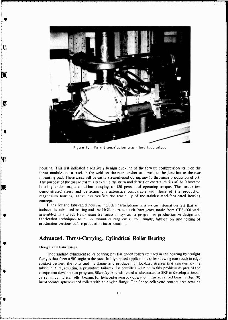
Figure 8. - Main transmission crash load test setup.
housing. This test indicated a relatively benign buckling of the forward corfipression strut on the input module and a crack in the weld on the rear tension strut weld at the junction to the rear mounting pad. These areas will be easily strengthened during any forthcoming production effort. The purpose of the torque test was to evalute the stress and deflection charactersitics of the fabricated housing under torque conditions ranging to 120 percent of operating torque. The torque test demonstrated stress and deflection characteristics comparable with those of the production magnesium housing. These tests verified the feasibility of the stainless-steel-fabricated housing concept.
Plans for the fabricated housing include: participation in a system integration test that will include the advanced bearing and the HGR buttress-toolh-form gears, made from CBS-600 steel, assembled in a Black Hawk main transmission system; a program to productionize design and fabrication techniques to reduce manufacturing costs; and, finally, fabrication and testing of production versions before production incorporation.
Advanced, Thrust-Carrying, Cylindrical Roller Bearing
Design and Fabrication
The standard cylindrical roller bearing has flat ended rollers retained in the bearing by straight flanges that form a 90° angle to the race. In high-speed applications roller skewing can result in edge contact between the roller and the flange and produce high localized stresses that can destroy the lubricant film, resulting in premature failures. To provide a solution to this problem as part of the component development program, Sikorsky Aircraft issued a subcontract to SKF to develop a thrust- carrying, cylindrical roller bearing for helicopter gearbox operation. This advanced bearing (fig. 10) incorporates sphere-ended rollers with an angled flange. The flange-roller-end contact area remains
I 14

•■•■ —^—I
Figure 9. - Main transmission torque test setup.
THRUST LOAD
Figure 10. - Thrust - roller bearing concept.
nearly circular under skewing, and thrust loads can be applied without excessive stress or breakdown in the lubricant film. Both bearing races were made from vacuum-induction-melted-vacuum-arc- remelted (VIM-VAR) AISI M-50 steel and heat treated to Rockwell C 60 (minimum); the cage was made from AMS 6414 steel and silver plated. VAR AISI M-50 steel rollers were used. The goals of this component development were to reduce weight, to improve reliability, to reduce cost, and to deteimine the validity of this bearing concept.
115
«■M*d
■!—• ■ ■ ■ "
Bearing Test
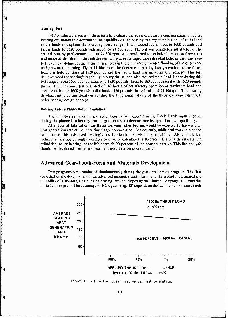
SKF conducted a series of three tests to evaluate the advanced bearing configuration. The first bearing evaluation test determined the capability of the bearing to carry combinations of radial and thrust loads throughout the operating speed range. This included radial loads to 1600 pounds and thrust loads to 1520 pounds with speeds to 21 500 rpm. The test was completely satisfactory. The second bearing performance test, at 21 500 rpm, was conducted to optimize lubrication flow rates and mode of distribution through the jets. Oil was centrifuged through radial holes in the inner race to the critical sliding contact areas. Drain holes in the outer race prevented flooding of the outer race and prevented churning. Figure 11 illustrates the decrease in bearing heat generation as the thrust load was held constant at 1520 pounds and the radial load was incrementally reduced. This test demonstrated the bearing's capability to carry thrust load with reduced radial load. Loads during this test ranged from 1600 pounds radial with 1520 pounds thrust to 160 pounds radial with 1520 pounds thrusi. The endurance test consisted of 140 hours of satisfactory operation at maximum load and speed conditions: 1600 pounds radial load, 1520 pounds thrust load, and 21 500 rpm. This bearing development program clearly established the functional validity of the thrust-carrying cylindrical roller bearing design concept.
Bearing Future Plans/Recommendations
The thrust-carrying cylindrical roller bearing will operate in the Black Hawk input module during the planned 10-hour system integration test to demonstrate its operational compatibility.
After loss of lubrication, the thrust-carrying roller bearing would be expected to have a high heat-generation rate at the inner-ring flange contact area. Consequently, additional work is planned to improve this advanced bearing's lost-lubrication survivability capability. Also, analytical techniques are not currently available to directly calculate the 10-percent life of a thrust-carrying cylindrical roller bearing, or the life at which 90 percent of the bearings survive. This life analysis should be developed before this bearing is used in a production design.
Advanced Gear-Tooth-Form and Materials Development
Two programs were conducted simultaneously during the gear development program: The first consisted of the development of an advanced geometry tooth form, and the second investigated the suitability of CBS-600, a carburizing bearing steel developed by the Timken Company, as a material for helicopter gears. The advantage of HCR gears (fig. 12) depends on the fact that two or more teeth
AVERAGE BEARING
HEAT GENERATION
RATE BTU/min
300
250-
200
150-
100
50-
1520 lbs THRUST LOAD
21,500 rpm
100 PERCENT = 1600 lbs RADIAL
-I 100%
—1— 75% V
O 25%
APPLIED THRUST LOAi JENCE
(WITH 1520 lbs THRUSi I_LIAD)
Figure 11. - Thrust - radial load versus heat generation.
116

1W* 1 '■ • -»■l ■ "ml '**','m: "- T"*!"^
FINAL POINT OF CONTACT
ADDENDUM
NORMAL PITCH
CONTACT ZONE
DEDENDUM ROTATION INITIAL POINT
OF CONTACT
Figure 12. - High-contact-ratio gearing.
HOT HARDNESS VS TEMPERATURE
ROCKWELL HARDNESS Rc
»BOEING VERTOL DATA Figure 13.
CBS 1000 CBS 600 VASCO X-2 9310 EX00053
1000 TIMKEN DATA
VASCO X2
200 400 600 800
TEMPERATURE
1000
Hardness versus temperature comparison.
teeth always share the transmitted load. Consequently, they"decrease the individual tooth load and the associated tooth bending and contact stresses. However, the means taken to increase the contact ratio (i.e., lower pressure angle, finer pitch, etc.) tend to reduce the tooth section. To offset this reduction in tooth section, Sikorsky Aircraft strengthened the tooth by increasing the pressure angle on the coast side, forming an asymmetrical, buttress-shaped tooth. High-contact-ratio buttressed gears offer the potential payoffs of increased strength and decreased noise level.
The advantage of CBS-600 as a potential gear material is its high temperature capability compared with 9310 steel (fig. 13). Although CBS-600 sacrifices some hot hardness when compared with other steels, its relatively low alloy compositions and high fracture toughness properties (fig. 14), warranted its evaluation for helicopter transmission gearing.
117
—^

-T-—»"T'--'- 1 5 ST - « ■
FRACTURE
TOUGHNESS
KT (KSI-IN1/»)
120 9310
100
80
60-
40-
20-
E^ CRACKS ORIGINATING IN CORE
mm CRACKS ORIGINATING IN CASE
(.50% C.)
52100
CBS 1000 VASCO X-2
TZZZZZl
M50
n |-450oFH [*-600OF-*| 300° F —
MAXIMUM SERVICE TEMPERATURE
Figure 14. - Material fracture toughness comparison.
TABLE 2 MATERIAL AND TOOTH FORM COMBINATIONS
MATERIAL TOOTH FORM j
9310
9310
CBS 600
CBS 600
HCR BUTTRESS \
STANDARD
HCR BUTTRESS j
STANDARD j
Gear-Tooth-Form and Material Evaluation Testing
The test program evaluated the improved gear tooth form and also determined the suitability of the hot-hardness steel as an aircraft-quality gear material. The evaluation test program consisted of two types of fatigue tests. The first was a series of constant-load dynamic tests on four gear configurations (table II) to determine their relative lives at a particular load level. The second fatigue test evaluated the CBS-600 material at variable load levels with a sufficient number of test points to generate a load-cycle curve for this material.
The 6.0-inch-diameter standard spur gear specimen (the baseline gear) had an 8-pitch symmetrical gear tooth with a HVi' pressure angle and a tooth contact ratio of 1.628. The advanced gear tooth was also 8-pitch with an asymmetric (buttress) shape, drive side pressure angle of 20°, coast side pressure angle of 25°, and with a contact ratio of 2.322. The CBS-600 is a case-hardening, carburizing bearing steel with superior hot-hardness characteristics compared with the standard 9310 (AMS 6265) steel.
118
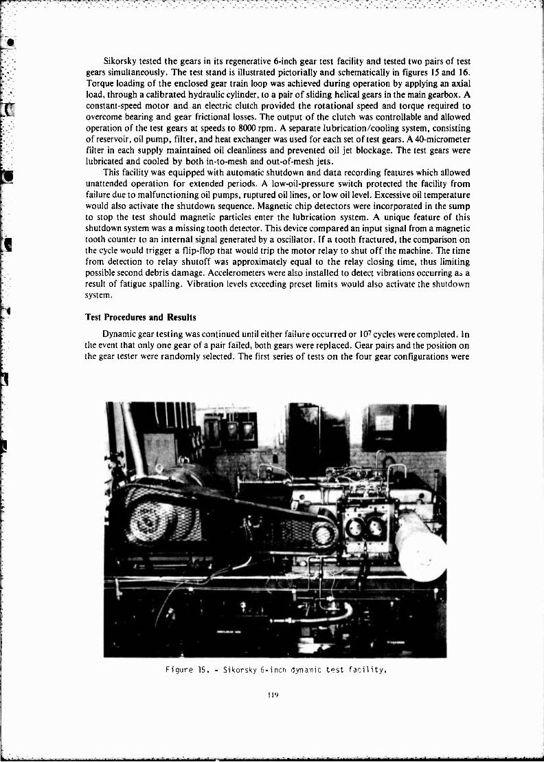
Sikorsky tested the gears in its regenerative 6-inch gear test facility and tested two pairs of test gears simultaneously. The test stand is illustrated pictorially and schematically in figures 15 and 16. Torque loading of the enclosed gear train loop was achieved during operation by applying an axial load, through a calibrated hydraulic cylinder, to a pair of sliding helical gears in the main gearbox. A constant-speed motor and an electric clutch provided the rotational speed and torque required to overcome bearing and gear frictional losses. The output of the clutch was controllable and allowed operation of the test gears at speeds to 8000 rpm. A separate lubrication/cooling system, consisting of reservoir, oil pump, filter, and heat exchanger was used for each set of test gears. A 40-micrometer filter in each supply maintained oil cleanliness and prevented oil jet blockage. The test gears were lubricated and cooled by both in-to-mesh and out-of-mesh jets.
This facility was equipped with automatic shutdown and data recording features which allowed unattended operation for extended periods. A low-oil-pressure switch protected the facility from failure due to malfunctioning oil pumps, ruptured oil lines, or low oil level. Excessive oil temperature would also activate the shutdown sequence. Magnetic chip detectors were incorporated in the sump to stop the test should magnetic particles enter the lubrication system. A unique feature of this shutdown system was a missing tooth detector. This device compared an input signal from a magnetic tooth counter to an internal signal generated by a oscillator. If a tooth fractured, the comparison on the cycle would trigger a flip-flop that would trip the motor relay to shut off the machine. The time from detection to relay shutoff was approximately equal to the relay closing time, thus limiting possible second debris damage. Accelerometers were also installed to detect vibrations occurring aa a result of fatigue spalling. Vibration levels exceeding preset limits would also activate the shutdown system.
Test Procedures and Results
Dynamic gear testing was continued until either failure occurred or 107 cycles were completed. In the event that only one gear of a pair failed, both gears were replaced. Gear pairs and the position on the gear tester were randomly selected. The first series of tests on the four gear configurations were
Figure 15. - Sikorsky 6-inch dynamic test facility.
11'»
- - - - . . - -

conducted at a 2~ pound tanaential tooth load. The results of these screenina tests are shown in figure 17. These are Weibull plots of the test data derived usina linear rearession analysis to determine the best fit line. Based on the life comparison at a 50 percent failure rate, the relative life rankin& of the four conf1.1urations are 9310 HCR buttress, 62; CBS-600 HCR, 10; CBS-600 standard, 4; and 9310 standard, 1. These plots show the considerable life advantage attributable to the HCR buttress tooth form. All of the gears tested, whose failure times are summarized in figure 17, exhibited the same failure mode-root bendina fatiaue. No surface pitting was evident in any of the test aears at the 2500-pound load level. The projected strenath advantage of the 9310 HCR buttress gears, compared with the baseline, calculated by drawina standard S-N curve shapes throuah the test data, and for endurance limits at 10 cycles, was approximately 19 percent, a substantial improvement. The benefits shown, however, for CBS-600 material indicate a Weibull slope of less than 1.0. which is uncharacteristic of material fatiJue tests of this kind. This may indicate the presence of another failure mechanism which is different from the classical fatigue failure mode. Additional testina is planned to thoroughly evaluate this material and to determine the significance of the low Weibull slopes.
The second dynamic fatiJue tests were designed to determine the load/life characteristics of th~: CBS-600 materials. A sample of 42gears was tested at various load levels to failure or run out at 107 cycles, whichever occurred first. The results of these tests are shown in figure 18. Similar test data for the 9310 HCR buttress configuration are not yet available to compare endurance limit loads or allowable operating stresses.
Durina the intitial testing of the CBS-600 steel gears, capping of the gear teeth occurred. Capping is the separation of a tooth comer at the intersection of the tip and tooth end face. Subsequent CBS-600 gears were machined with a full 0.03-inch edge break on the gear teeth. It was reasoned that by increasing the edge break, the load at the edge of the tooth would be relieved and redistributed over a larger area, thus reducina the possibility of tooth tip fractures. Similar capping did not occur for the 9310 material.
Durina the intitial dynamic fatigue tests, some slight scuffina was noted on the tooth tips of the HCR buttress gears. Because of this tendency to scuff, the tip profde modification on the CBS-600 HCR buttress gears was increased before running the load/cycle fatigue tests. This modification
LOADING CYLINDER
INPUT MOTOR
4SOUARE RIG
TEST GEARS NO. 1
Figure 16. - Test facility schematic.
120

105
Figure 17,
io6 io7
Results - constant load fatigue tests.
4000
3800
3600
3400
3200
3000
2800
POt'iDS fi/jQ
2400
2200
2000
1800
1600
1400
1200
1000
I 1
V 1
V \ \
"l i NCU RVE- ^MEA
1 • r- L. .
1
10" IO5 IO6
CYCLES TO FRACTURf
107 10°
Figure 18. - Results - Load/cycle fatigue tests for CBS-600.
allowed for the greater-than-anticipated deflection of the HCR gears at the high loads and prevented load concentration in the upper portion of the tooth profile. Unfortunately, gears relieved to run well at the high load level suffer somewhat at the lower loads and can result in a lower endurance limit. This is particularly true of HCR gears which are more sensitive to tooth errors and profile modification than standard tooth form gears.
121
J

System Integration Tests
Sikorsky Aircraft will conduct the system integration tests using a Black Hawk main transmission that includes the fabricated stainless-steel housing, the advanced, thrust-carrying, cylindrical roller bearing, and the HCR buttress-tooth-form planetary made from CBS-600 steel. The purpose of these tests is to determine the capability of these advanced components to operate compatibly with the other Black Hawk main transmission dynamic components.
This series of tests will be conducted in the Black Hawk main transmission regenerative test facility. The test transmission will be connected through interconnecting shafts to a dummy aircraft main transmission and commercial gearboxes that subject the test gearbox to torque loads simulating and exceeding flight loads. Sliding helical gears in the commercial gearboxes control the input and tail rotor torque loads. Direct current electric motors provide rotational speeds up to 110 percent times normal aircraft rated speed. Thirty-eight thermocouples will monitor oil, bearing, gear, and housing temperatures. Sikorsky will also monitor oil pressure and flow, torque, and vibration.
A lubrication test will verify proper operation of the gearbox lubrication system and will include measurements of temperature, flow rates, and pressures that will be compared with baseline test data. A preliminary load test will verify acceptable transmission performance and will consist of loading the system incrementally up to full load at operating speed and then comparing test data with baseline test data. Disassembly of the transmission after completion of this test will permit a visual examination of gear patterns, then we will conduct a 10-hour evaluation test at Black Hawk qualification loads. At the completion of this evaluation test, we will conduct a split inspection of the gearbox to determine the condition of the test components. An oil cooler bypass test will evaluate the high-temperature operating capabilities of the advanced bearing design, fabricated housing and HCR buttress-tooth-form planetary gears for 10 hours or until the oil temperature reaches 400° F, whichever occurs first.
The results of these tests will be published in a forthcoming report.
Conclusions The fabricated stainless-steel housing provides a lightweight, high-temperature capability,
improved life cycle cost, corrosion resistant approach to helicopter gearbox housing application. The thrust-carrying cylindrical roller bearing offers a viable solution for high-speed operation under load conditions that include both thrust and radial loads. The HCR buttress-tooth-form gearing demonstrated superior strength over the baseline standard spur tooth form regardless of material selection; also, CBS-600 is suitable gear material for high-temperature operation. This investigation presents the helicopter tranmission designer with three advanced components to use as design options and an advanced hot-hardness gear material to use after its design allowables are established.
\
122
*■ - - -