An overview of advancements in electrochemical compressor...
10
An overview of advancements in electrochemical compressor driven heat pump systems Bamdad Bahar a* , William Parmelee a , Scott Fackler a , Richard Sherrer a , Jacob Zerby a Omar Abdelaziz b , Qu Ming b , Brent Junge c , David Beers c , Ajay Prasad d a Xergy Inc , 105 Park Ave, Seaford, Delaware 19973, U.S.A b ORNL One Bethel Valley Rd.,Oak Ridge, TN 37831-6070, U.S.A c GE Appliances, a Haier Company, 4000 Buechel Bank Rd, Louisville, KY 40225, U.S.A . d University of Delaware, Newark, DE 19716-3140, U.S.A. Abstract A comprehensive overview of the state-of-the art in applying electrochemical compressors to heat pump systems is provided. The theoretical foundations for the technology are considered, followed by a review of thermodynamic cycles employing electrochemical compressors. Two illustrative case study demonstration systems are described: (1) a hybrid hot water heater with a combined electrochemical compressor and a liquid cooled metal hydride heat exchanger using hydrogen as the working fluid, (2) a water chiller system employing an electrochemical compressor with water as the working fluid. The second system may be extended to work with different refrigerants such as ammonia, carbon dioxide and organic fluids. © 2017 Stichting HPC 2017. Selection and/or peer-review under responsibility of the organizers of the 12th IEA Heat Pump Conference 2017. Keywords: electrochemistry; compressor; heat pump; hydrogen 1. Background Heat pumps and refrigeration systems remove heat from a heat source or reservoir at low temperature and reject the heat to a heat sink or reservoir at high temperature. While many thermodynamic effects have been exploited in the development of heat pumps and refrigeration cycles, one of the most popular today is the vapor compression cycle approach. This approach is sometimes called mechanical or mechanical-electric refrigeration because a mechanical compressor is used. Based on information in the U.S. DOE “Buildingsdatabook” web site, buildings consume 40% of the primary energy and account for 40% of CO2 emissions in the United States. Buildings use 72% of the nation’s electricity and 55% of natural gas (1). The energy use in the residential and commercial building sector is roughly split in half. From 2006 to 2030, the US population is expected to increase by 21%, while the number of households is expected to increase by 25%. Commercial space is expected to increase by 35% over the same period. Building floor space is increasing at a much faster rate in developing countries such as China and India compared to the US. It is expected that floor space will increase at an annual rate of 8.5% in India from 2010 to 2030, and at an annual rate of 3.5% in China, which will lead to significant increase in demand for energy in the building sector worldwide. Space cooling accounts for approximately 12.7% of primary energy consumption in buildings and accounts for 13% of CO2 emissions from buildings in US. This amounts to ~5% of primary energy consumption and ~ 5% of CO2 emissions in US (2). Therefore, energy efficiency measures in the buildings sector provide a tremendous opportunity to reduce the energy demand and reduction in greenhouse gas (GHG) emissions.
Transcript of An overview of advancements in electrochemical compressor...

An overview of advancements in electrochemical compressor
driven heat pump systems
Bamdad Bahara*, William Parmeleea, Scott Facklera, Richard Sherrera, Jacob Zerbya
Omar Abdelazizb, Qu Mingb, Brent Jungec, David Beersc, Ajay Prasadd
aXergy Inc , 105 Park Ave, Seaford, Delaware 19973, U.S.A bORNL One Bethel Valley Rd.,Oak Ridge, TN 37831-6070, U.S.A
cGE Appliances, a Haier Company, 4000 Buechel Bank Rd, Louisville, KY 40225, U.S.A
.dUniversity of Delaware, Newark, DE 19716-3140, U.S.A.
Abstract
A comprehensive overview of the state-of-the art in applying electrochemical compressors to heat pump systems
is provided. The theoretical foundations for the technology are considered, followed by a review of
thermodynamic cycles employing electrochemical compressors. Two illustrative case study demonstration
systems are described: (1) a hybrid hot water heater with a combined electrochemical compressor and a liquid
cooled metal hydride heat exchanger using hydrogen as the working fluid, (2) a water chiller system employing
an electrochemical compressor with water as the working fluid. The second system may be extended to work
with different refrigerants such as ammonia, carbon dioxide and organic fluids.
© 2017 Stichting HPC 2017.
Selection and/or peer-review under responsibility of the organizers of the 12th IEA Heat Pump Conference 2017.
Keywords: electrochemistry; compressor; heat pump; hydrogen
1. Background
Heat pumps and refrigeration systems remove heat from a heat source or reservoir at low temperature and reject
the heat to a heat sink or reservoir at high temperature. While many thermodynamic effects have been exploited
in the development of heat pumps and refrigeration cycles, one of the most popular today is the vapor
compression cycle approach. This approach is sometimes called mechanical or mechanical-electric refrigeration
because a mechanical compressor is used.
Based on information in the U.S. DOE “Buildingsdatabook” web site, buildings consume 40% of the primary
energy and account for 40% of CO2 emissions in the United States. Buildings use 72% of the nation’s electricity
and 55% of natural gas(1). The energy use in the residential and commercial building sector is roughly split in
half. From 2006 to 2030, the US population is expected to increase by 21%, while the number of households is
expected to increase by 25%. Commercial space is expected to increase by 35% over the same period. Building
floor space is increasing at a much faster rate in developing countries such as China and India compared to the
US. It is expected that floor space will increase at an annual rate of 8.5% in India from 2010 to 2030, and at an
annual rate of 3.5% in China, which will lead to significant increase in demand for energy in the building sector
worldwide. Space cooling accounts for approximately 12.7% of primary energy consumption in buildings and
accounts for 13% of CO2 emissions from buildings in US. This amounts to ~5% of primary energy consumption
and ~ 5% of CO2 emissions in US(2). Therefore, energy efficiency measures in the buildings sector provide a
tremendous opportunity to reduce the energy demand and reduction in greenhouse gas (GHG) emissions.
Bahar et al / 12th IEA Heat Pump Conference (2017) O.4.9.4
2
Refrigerants used in vapor compressions systems for space cooling are another source of greenhouse gas (GHG)
emissions. More than 90% of cooling is provided by vapor compression based systems in the US. The global
warming potential (GWP) of refrigerants such as hydrochloroflurocarbons (HCFC) and hydrofluorocarbons
(HFC) are typically more than 1000 times that of CO2. Although the current contribution of GHG due to HCFC,
HFC and chlorofluorocarbons (CFC) in US is ~1%, a recent report (3&4) suggests that the global GHG emissions
from these chemicals in 2050 could be equivalent to 9–19% (CO2-equivalent basis) of projected global CO2
emissions in business-as-usual scenarios. This percentage increases to 28–45% compared with projected CO2
emissions in a 450-ppm CO2 stabilization scenario. Due to significant increase in the demand for air conditioners
and refrigerators in developing countries, GHG emissions due to refrigerants from developing countries can be
as much as 800% greater than in developed countries by 2050.
The compressor is usually the major energy consuming component of the system; as such, any improvement in
its efficiency as well as reduction in the use of conventional refrigerants can have significant benefits in terms of
energy savings and GHG emissions and thus have significant positive environmental impact. Advanced
compressor technology would enable the use of heat pump systems beyound just building applications; it may
enable the use of more efficient cooling technologies in electric vehicles as well as other thermal management
problems of varying capacities and sizes.
The use of electrochemical compression (ECC) for heat pump applications is a new, disruptive technology that
holds the potential of addressing these challenges. This technology is based on components originally developed
for fuel cells, used in a novel fashion. ECC provides an improved means to compress a working fluid at higher
efficiencies, without the need for conventional refrigerants. It is also modular, scalable, and essentially a
noiseless and vibration free (solid state) technology, with numerous other practical benefits in use depending on
the specific application.
It is important to recognize that ECC is a “platform” technology, which can be applied in many different ways,
with different working fluids and different thermodynamic cycles. This paper explores the current state of the art
in applying ECC to heat pump applications, and provides practical examples of demonstration systems.
2. Electrochemical Compression
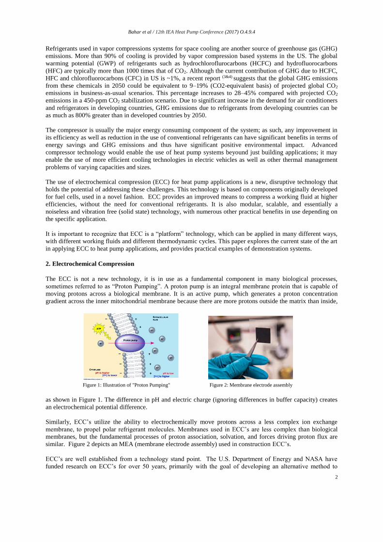
The ECC is not a new technology, it is in use as a fundamental component in many biological processes,
sometimes referred to as “Proton Pumping”. A proton pump is an integral membrane protein that is capable of
moving protons across a biological membrane. It is an active pump, which generates a proton concentration
gradient across the inner mitochondrial membrane because there are more protons outside the matrix than inside,
as shown in Figure 1. The difference in pH and electric charge (ignoring differences in buffer capacity) creates
an electrochemical potential difference.
Similarly, ECC’s utilize the ability to electrochemically move protons across a less complex ion exchange
membrane, to propel polar refrigerant molecules. Membranes used in ECC’s are less complex than biological
membranes, but the fundamental processes of proton association, solvation, and forces driving proton flux are
similar. Figure 2 depicts an MEA (membrane electrode assembly) used in construction ECC’s.
ECC’s are well established from a technology stand point. The U.S. Department of Energy and NASA have
funded research on ECC’s for over 50 years, primarily with the goal of developing an alternative method to
Figure 1: Illustration of "Proton Pumping" Figure 2: Membrane electrode assembly
Bahar et al / 12th IEA Heat Pump Conference (2017) O.4.9.4
3
provide high pressure hydrogen gas streams (typically hundreds of bars), without the use of mechanical
compressors for application such as for Hydrogen ‘gas stations’ where hydrogen is fed into automotive storage
cylinders at 2000 psi (13.8 MPa). Figure 3 below shows some of the ECC’s developed under these programs.
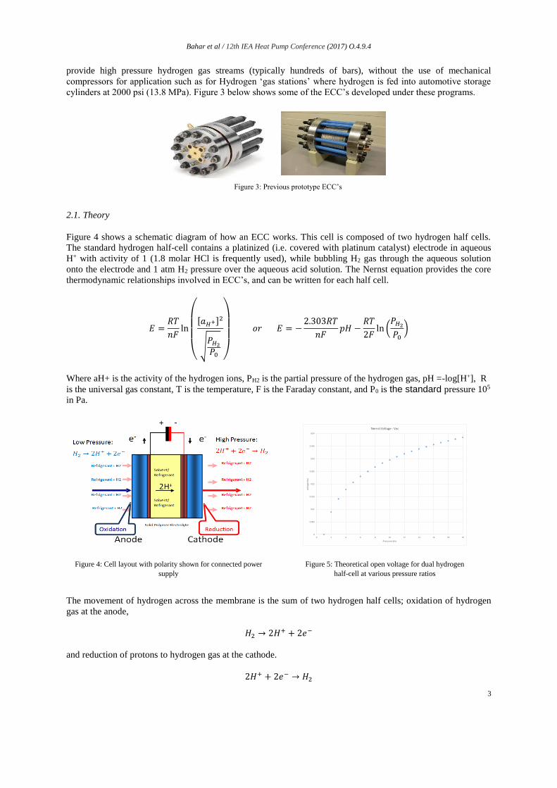
2.1. Theory
Figure 4 shows a schematic diagram of how an ECC works. This cell is composed of two hydrogen half cells.
The standard hydrogen half-cell contains a platinized (i.e. covered with platinum catalyst) electrode in aqueous
H+ with activity of 1 (1.8 molar HCl is frequently used), while bubbling H2 gas through the aqueous solution
onto the electrode and 1 atm H2 pressure over the aqueous acid solution. The Nernst equation provides the core
thermodynamic relationships involved in ECC’s, and can be written for each half cell.
𝐸 =𝑅𝑇
𝑛𝐹ln
(
[𝑎𝐻+]
2
√𝑃𝐻2𝑃0 )
𝑜𝑟 𝐸 = −2.303𝑅𝑇
𝑛𝐹𝑝𝐻 −
𝑅𝑇
2𝐹ln (𝑃𝐻2𝑃0)
Where aH+ is the activity of the hydrogen ions, PH2 is the partial pressure of the hydrogen gas, pH =-log[H+], R
is the universal gas constant, T is the temperature, F is the Faraday constant, and P0 is the standard pressure 105
in Pa.
The movement of hydrogen across the membrane is the sum of two hydrogen half cells; oxidation of hydrogen
gas at the anode,
𝐻2 → 2𝐻+ + 2𝑒−
and reduction of protons to hydrogen gas at the cathode.
2𝐻+ + 2𝑒− → 𝐻2
0
0.005
0.01
0.015
0.02
0.025
0.03
0.035
0.04
0 2 4 6 8 10 12 14 16 18 20
volt
age
=Vo
c
Pressure ratio
Nernst Voltage - Voc
Figure 3: Previous prototype ECC’s
Figure 4: Cell layout with polarity shown for connected power
supply Figure 5: Theoretical open voltage for dual hydrogen
half-cell at various pressure ratios
Bahar et al / 12th IEA Heat Pump Conference (2017) O.4.9.4
4
The electro-potential for this cell is 0 volts assuming the same pressure on each side of the membrane, since it is
the mirror image reaction on each side of the membrane. If there is a pressure rise across the membrane, then
there is a potential that is required to maintain that pressure ratio. This voltage is equal to the theoretical open
circuit Nernst voltage based on the pressure cell as given by VOC.
𝑉𝑂𝐶 =𝑅𝑇
2𝐹ln (𝑃𝑐𝑎𝑡ℎ𝑜𝑑𝑒𝑃𝑎𝑛𝑜𝑑𝑒
)
If the cell is operated at no pressure gradient and at very close to 0 volts, or at VOC for the pressure ratio across
the cell, the cell would have exceedingly high efficiency, but virtually no flow. The difference between the
required applied voltage and the equilibrium voltage for the cell is the operating over voltage.
New theoretical equations for performance need to be established based on fundamental thermodynamics.
Rearranging the universal equation for Gibbs free energy leads us with the following equation:
𝑇∆𝑆
∆𝐻= 1 −
∆𝐺
∆𝐻
The change in Gibbs free energy can be expressed as nFE, and the change in enthalpy can be expressed as VdP,
assuming isentropic gas compression. Applying these changes to the above equation leads to an expression to
calculate isentropic efficiency (TΔS/ΔH).
𝜂𝑠 =−𝑛𝐹𝐸
𝑉𝑑𝑃
The electrochemical performance of the cell can be understood by realizing that the chemistry of the cell consists
of a series of steps. The electroactive material, e.g. H2, must adsorb onto the anode catalyst surface on the
membrane (kadsorb), adsorbed hydrogen and can then lose an electron via electron transfer to the catalyst (keto).
The protons move through the membrane to the cathode catalyst (kpt) and gain an electron via electron transfer
from the catalyst (ketr), the H2 created desorbs from the cathode surface. The cathodic steps are much faster than
the anodic steps, so the rate limiting (and current limiting) steps are the adsorption of the H2 onto the catalyst
surface and the electron transfer from H2 to the catalyst. The anodic electron transfer rate (keto) is proportional to
the voltage difference between the anode catalyst and the equilibrium voltage for the cell. In this case 0 volts,
when operated at no pressure differential.
To increase the mass transport of the hydrogen one has two choices: (a) to increase the cell area or (b) to increase
the voltage driving the kinetics of the reaction. There are two competing setups: (i) high efficiency requiring low
voltage and very high membrane area or (ii) lower membrane area with higher voltage resulting in lower
efficiency. One therefore must pick an operating voltage that provides the required mass transport at an
acceptable cost effective position, while balancing operating efficiency against fabrication cost.
A polarization curve is the plot of the cell current vs. the applied voltage. The curve is a summation of all losses.
A perfect cell would have no losses; the electron transfer rates would be infinite, there would be no cell electrical
resistance (ohmic loss) and the mass transfer rates for all species would be infinite. Under those conditions the
current would not be controlled by the cell, but by the power supply. For any applied voltage the current would
be equal to what the power supply could deliver. Under realistic conditions, with all three losses present, you
typically see a curve with three distinct slopes and shapes. The initial portion is linear, frequently with a shallow
slope (activation or electron transfer rate controlled), then a portion that is linear with a higher slope, where the
cells electrical resistance controls current flow, then a region where the electrode surfaces are becoming starved
of reactant H2 gas. This last portion the system is mass transport limited. The curve is not linear, frequently
exhibits lower current at higher voltage, and always reduced current vs. the linear extrapolation from the ohmic
portion of the curve, which is shown in Figure 6a. One important feature of electrochemical energy conversion is
the intrinsically higher exergy efficiencies these systems can provide. They have demonstrated exergy
efficiencies more than 75% at low voltage operation, as shown in the Figure 6b, and can easily produce very
high pressures.

Bahar et al / 12th IEA Heat Pump Conference (2017) O.4.9.4
5
2.2. Ion-exchange membranes
At the heart of an ECC is an ion-exchange membrane with two (catalytic) electrodes.The entire assembly is
referred to as a membrane-electrode assembly (MEA). Ion-exchange membranes transport dissolved ions across
a conductive polymeric membrane, often referred to as an ‘ionomer’. Ion-exchange membranes are made of a
polymeric material attached to charged ion groups. Anion-exchange membranes contain fixed cationic groups
with predominantly mobile anions; because anions are the majority species, most of the conductivity is due to
anion transport. Cation-exchange membranes contain fixed anionic groups with predominantly mobile cations;
because cations are the majority species, most of the conductivity is due to cation transport. The selectivity of the
membranes is due to Donnan equilibrium and Donnan exclusion and not due to physically blocking or
electrostatically excluding specific charged species.
3. Heat pumps using electrochemical compressors
Electrochemical Compressors can be employed with many different working fluids and thermodynamic cycles.
In their simplest form, the compressors can compress hydrogen, or they can use proton pumping to compress
another working fluid such as water. Case studies illustrating heat pump systems with different working fluids
are explored below. One common element that should be emphasized is that for these heat pump cycles,
electrochemical compression at ‘lower pressures’ than has traditionally been developed in the past are required,
and needed to be developed from the ‘ground up’.
3.1. ECC with H2 as the working fluid
With Hydrogen as the working fluid, an electrochemical hydrogen compressor is supplied with hydrogen to the
anode, and compressed hydrogen is generated at the cathode.
In one configuration, these compressors can be combined with metal hydride heat exchangers to provide heating
and cooling. Metal hydrides (MHx) are metallic compounds, in which one or more hydrogen centers have
Figure 6a: Polarization curve
Figure 7: Overview of ECC heat pumps Figure 8: ECC design with metal hydride heat
exchangers
Figure 6b: Voltage vs. Efficiency correlation

Bahar et al / 12th IEA Heat Pump Conference (2017) O.4.9.4
6
nucleophilic, reducing, or basic properties. For heat pumps, we utilize the reversible heat-driven reaction of a
hydride-forming metal/alloy, or intermetallic compound (IMC) with hydrogen adsorption/desorption.
𝑀(𝑠) +𝑥
2𝐻2(𝑔) ⇄ MHx(s) + Q
Where M is the metal/alloy and Q is the reaction enthalpy. The overall process performance is strongly
dependent on the intrinsic features of the reaction, including its thermodynamic and kinetic characteristics, as
well as composition, structure and morphology of the solid phases (M, MHx) involved in the process. These
features are mainly related to fundamental aspects of Hydride materials. As enthalpy adsorption increases (from
20 to 80 KJ/mol H2), system efficiency improves, as illustrated in Figure 9.
The equilibrium of the metal hydride reaction is characterized by an interrelation between hydrogen pressure (P),
concentration of hydrogen in the solid phase (C) and temperature (T). P-C-T diagrams can be generated to
characterize specific hydride-forming materials. These provide the thermodynamics of its interaction with
gaseous hydrogen. At low hydrogen concentrations (0 ≤ C < a) hydrogen atoms form an interstitial solid solution
in the matrix per Henry–Sieverts law. When the value of C exceeds concentration of the saturated solid solution,
precipitation of the hydride (β-phase with hydrogen concentration) occurs. The system then exhibits a first order
phase transition at a constant hydrogen pressure, P = PP (a ≤ C ≤ b). This pressure is called the plateau pressure
in diagrams of the metal–hydrogen systems. The process is almost perfectly (100%) reversible, with slight
differences as concentration changes. This is termed hysteresis, and is a source of efficiency loss (<5%).
Hydrogen compression ratio (PH/PL) for Hydrides can vary in the range 10 – 50. Xergy’s one stage ECC’s, are
sufficient to drive hydride systems.
Van't Hoff plots for selected hydride-forming alloys are provided in Figure 10. Depending on the composition of
the hydride-forming material, the equilibrium hydrogen pressures vary in a broad range, from below 1 bar to
exceeding 1 kbar at room temperature. Most of the lower-pressure compression alloys (PH <200 bar at TH
<150°C) belong to the AB5-type intermetallic compounds, while significantly higher, >1 kbar, hydrogen,
pressures can be generated using AB2-type compounds. The AB2 compounds have significantly
higher enthalpy of adsorption, and higher percentage hydrogen storage capacity. Xergy has built systems with a
wide range of commercial AB5 compounds. With AB2 compounds, a much higher thermal exchange capacity is
feasible, i.e. smaller heat exchangers. Proper hydride selection is critical to designing useful metal hydride heat
exchangers.
Figure 10: Van’t Hoff Plot Figure 9: Different ∆H Hydrides: System COP vs ECC Voltage
Bahar et al / 12th IEA Heat Pump Conference (2017) O.4.9.4
7
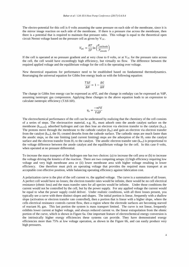
For durable performance, hydride systems must remain dry. Electrochemical compressor driven hydride heat
exchangers are dual modular systems. A schematic of the system is provided in Figures 11a and 11b. Xergy plans
to work on these two components simultaneously, and deliver a range of elements that can be cross-selected to
meet specific applications. Since each application has a different desired source and sink temperatures, several
different hydride heat exchangers will be developed, with standard fittings that can connect with the ECC stack.
These systems are also designed to be modular, and therefore can operate at variable pressures and hydrogen
flow rates.
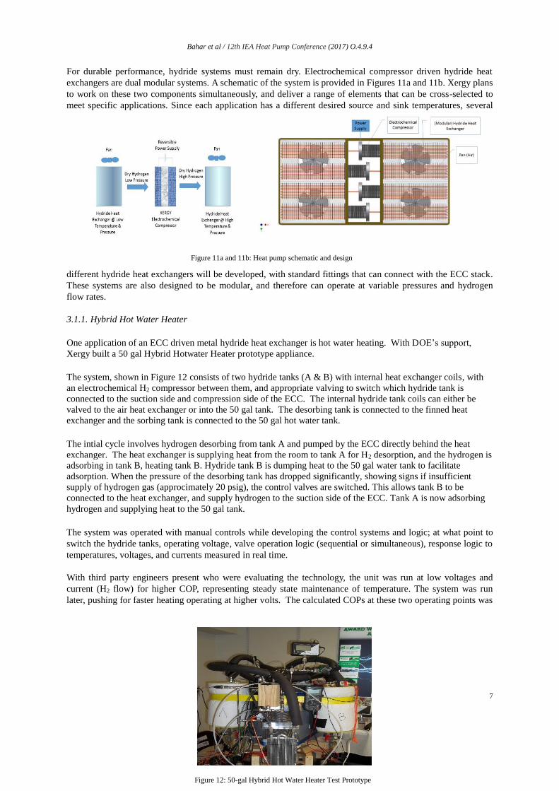
3.1.1. Hybrid Hot Water Heater
One application of an ECC driven metal hydride heat exchanger is hot water heating. With DOE’s support,
Xergy built a 50 gal Hybrid Hotwater Heater prototype appliance.
The system, shown in Figure 12 consists of two hydride tanks (A & B) with internal heat exchanger coils, with
an electrochemical H2 compressor between them, and appropriate valving to switch which hydride tank is
connected to the suction side and compression side of the ECC. The internal hydride tank coils can either be
valved to the air heat exchanger or into the 50 gal tank. The desorbing tank is connected to the finned heat
exchanger and the sorbing tank is connected to the 50 gal hot water tank.
The intial cycle involves hydrogen desorbing from tank A and pumped by the ECC directly behind the heat
exchanger. The heat exchanger is supplying heat from the room to tank A for H2 desorption, and the hydrogen is
adsorbing in tank B, heating tank B. Hydride tank B is dumping heat to the 50 gal water tank to facilitate
adsorption. When the pressure of the desorbing tank has dropped significantly, showing signs if insufficient
supply of hydrogen gas (approcimately 20 psig), the control valves are switched. This allows tank B to be
connected to the heat exchanger, and supply hydrogen to the suction side of the ECC. Tank A is now adsorbing
hydrogen and supplying heat to the 50 gal tank.
The system was operated with manual controls while developing the control systems and logic; at what point to
switch the hydride tanks, operating voltage, valve operation logic (sequential or simultaneous), response logic to
temperatures, voltages, and currents measured in real time.
With third party engineers present who were evaluating the technology, the unit was run at low voltages and
current (H2 flow) for higher COP, representing steady state maintenance of temperature. The system was run
later, pushing for faster heating operating at higher volts. The calculated COPs at these two operating points was
Figure 11a and 11b: Heat pump schematic and design
Figure 12: 50-gal Hybrid Hot Water Heater Test Prototype
Bahar et al / 12th IEA Heat Pump Conference (2017) O.4.9.4
8
2.8 and T=1.4, respectively, and very close to those predicted by our model.
Table 1: Testing results for 50 gal hybrid hot water heater
Test GE Test Heat-up Test 1 Heat-up Test 2
ΔT (C) 0.59 0.61 0.37
Mass (kg) 146.5 146.5 146.5
Cp (J/kg-K) 4184 4184 4184
Q (kJ) 36.4 30.0 31.4
Time (s) 4032 790.6 1125
Avg. ECC Power Input (W) 32.0 38.0 27.9
HWH Heat Rate (W) 90.4 54.6 36.5
COP 2.82 1.44 1.31
3.2. ECC with water as a working fluid
Bloomfield(5) filed a patent on an ECC that could drive water, but had difficulty building a prototype. Every
proton being driven across an ion exchange membrane carries a solvation shell of water molecules with it. Xergy
has measured water transport and arrived at a number slightly above 1 (for PFSA membranes in aqueous media).
However, there are many applications, such as “chlor-alkali” plants, where transport numbers in the region of 4
are used as a design parameter. Obviously, pushing Chlorine ions across the membrane is a different task to
driving protons. Also, it is important to note, transport of ions, and polar species with them, is very complex and
related to the core ‘chemistry’ of the ion exchange membrane (and operating conditions).
Vapor Compression of water requires operation under sub-ambient conditions. A review of water’s pressure-
enthalpy diagram shows the ‘whole cycle’ sitting below atmospheric pressure. One key benefit of
electrochemical compression is that it can operate under these conditions. Water is an excellent refrigerant, but
not easily compressible using standard mechanical compressors. ECC’s capacity to compress water is clearly a
breakthrough in many ways.
However, because of the sub-ambient conditions, Xergy’s cell design for this application had to be considerably
different to any ECC built in the past, even to Xergy’s low pressure compressors for metal hydride heat
exchangers.
For a refrigeration cycle operating between a lower limit, or source temperature, and an upper limit, or sink
temperature, the maximum efficiency of the cycle is limited to the Carnot efficiency. The efficiency of a
refrigeration cycle is generally defined by its coefficient of performance (COP), which is the quotient of the heat
absorbed from the sink divided by the net-work input required by the cycle.
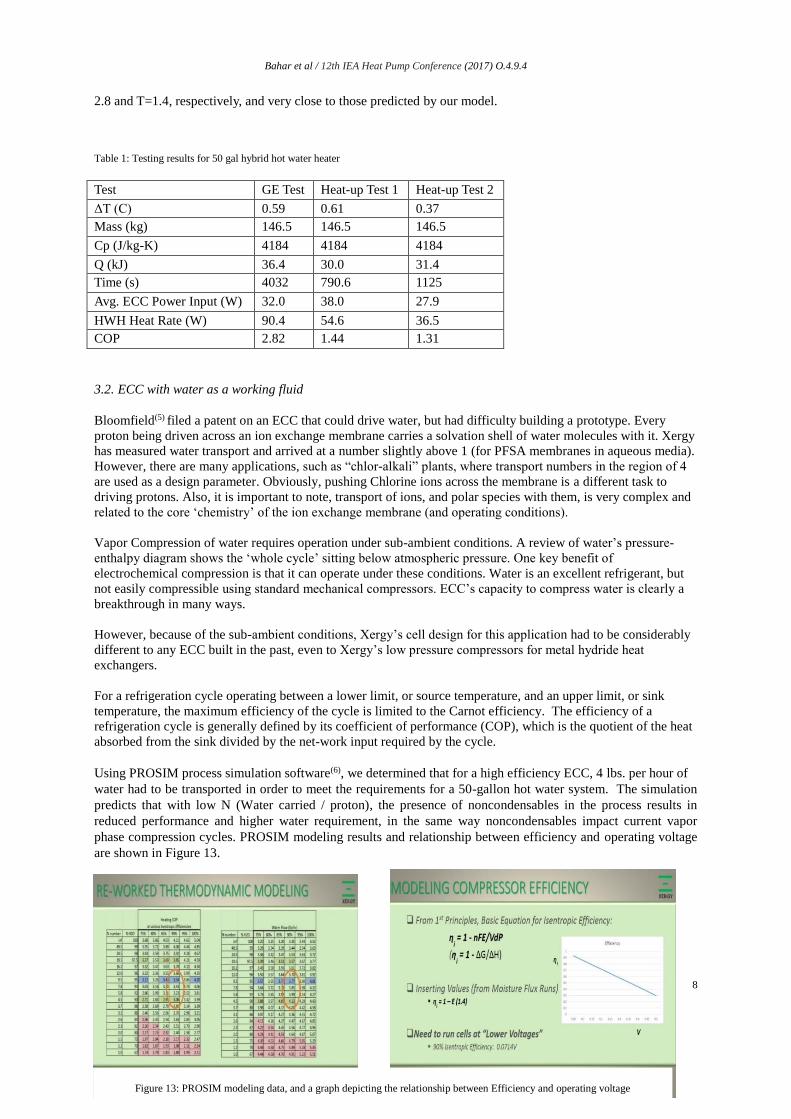
Using PROSIM process simulation software(6), we determined that for a high efficiency ECC, 4 lbs. per hour of
water had to be transported in order to meet the requirements for a 50-gallon hot water system. The simulation
predicts that with low N (Water carried / proton), the presence of noncondensables in the process results in
reduced performance and higher water requirement, in the same way noncondensables impact current vapor
phase compression cycles. PROSIM modeling results and relationship between efficiency and operating voltage
are shown in Figure 13.
Figure 13: PROSIM modeling data, and a graph depicting the relationship between Efficiency and operating voltage

Bahar et al / 12th IEA Heat Pump Conference (2017) O.4.9.4
9
For this application, we utilized our narrow edge-ported cells contained within a pressure housing. Our initial
designs were square/rectangular, and while they provided expected electrical performance, they did not perform
acceptably in maximum pressure tests.
General Electric Appliances has performed heat exchanger analysis, flow analysis and physical construction
analysis to determine specifications of materials required and performed initial sizing of components. The
technology operating with steam as the refrigerant presents unique challenges. The density of steam at low
pressures requires large volumetric flow rates to provide useful capacity. To prevent excessive pressure drops at
such flow velocities, large tubes manifold is required to reduce flow distance.
Almost concurrent with the delivery of the electrochemical water compressor to GE Appliances, Xergy was
approached by Dais-Analytic Corporation (Florida) working in conjunction with Oak Ridge National Laboratory
(ORNL) on novel membrane chiller system that also required water compression. Xergy has built a prototype
unit for DAIS/ORNL, and will conduct joint testing on this unit in 2017. A picture of a sub-stack for this system
is provided in Figure 14.
3.3. ECC with other working fluid
The concept (and modeling) for an electrochemical compressor driven heat pump with ammonia as a working
fluid was first developed by David Bloomfield (Analytic Power) in 1994 and subsequently described by Newton
(IIT), in 1998.
We performed consderable tests on these systems and sponsored a student summer project on this concept. ECC
of Ammonia has been disclosed for a long time. As with any new heat pump technology, the core issue is system
efficiency, and the rate of reactions. The transport mechanisims of ammonium ions in cationic membranes is
well established. A fundamental issue is the lack of mobility of ammonium ions in a polymer matrix containing
sulfonic or carboxylic acid matrix. The increased polarity of ammonium means it ‘prefers’ to remain highly
bound to acid groups – and in fact impedes even proton mobility. In fuel cell applications, the presence of
ammonia in hydrogen gas streams is considered to be a contaminant, reducing cell performance. Considerable
investments have been made to reduce ammonia production in hydrogen reformers precisely for this reason.
Never-the-less, there is sufficient movement for some ammonia to be transported with subsequent increase in
pressure on the cathode, but it requires a lot of work. So far, reported outcomes don’t suggest that high
efficiencies are feasible.
Both cation and anion exchange membranes can be used to pump materials across a membrane. Xergy has filed
patents for ammonia compression and is currently working with leading universities on applications of
proprietary anionic exchange membranes including compression. We are developing electrochemical
compressor systems for Ammonia and carbon dioxide which we believe will be more reliable than current
mechanical compressors. In theory any sufficiently polarizable molecule can associate with the cation or anion
exchanged across the membrane being pumped across with the ion.
Figure 14: Sub stack for water compression ECC

Bahar et al / 12th IEA Heat Pump Conference (2017) O.4.9.4
10
4. Conclusion
This paper has identified different heat pump systems using ECC’s – operating with different working fluids and
transport mechanisms. Heat pumps employing ECC’s are a transformative and disruptive platform technology.
The core theoretical basis underlying ECC confirms from first principles that the technology has the potential to
provide higher operating efficiencies. We showed that from fundamental thermodynamic analysis, that ECC’s
can be more efficient (i.e. have inherently high COP’s) than conventional mechanical compressors. In addition,
they are (a) motor-less and therefore most reliable and noiseless, (b) do not use CFC’s and are therefore non-
GHG, environmentally-friendly, (c) modular and scalable, (d) can operate very efficiently at partial loads, and
(e) can be designed to different form factors. There are numerous other benefits of this technology that can
surface depending on the use. Thus, this compression technology provides an excellent platform for the
development of heat pumps that are “more efficient, noiseless, vibration free, modular and scalable for polar
(natural, non-GHG) refrigerants” for refrigeration/HVAC type applications. Xergy has demonstrated 5 sequential
generations of ECC’s, for multiple applications such as hybrid hot water heaters and air conditioners reducing
weight and volume by several orders of magnitude approaching commercial market entry targets.
Acknowledgements
This research was supported by US DOE Building Technologies Office, Small Business Innovation programs.
Xergy Inc. received a $100,000 award from GE’s Ecomagination competition which also supported the
construction of the first-generation low pressure ECC demonstration systems.
References
(1) DOE Buildings Energy Data Book Data retrieved from http://buildingsdatabook.eren.doe.gov/
(2) BEETIT_ProgramOverview.pdf https://arpa-
e.energy.gov/sites/default/files/documents/files/BEETIT_ProgramOverview.pdf
(3) HFCs: A Critical Link in Protecting Climate and the Ozone Layer retrieved from
http://www.unep.org/publications/ebooks/hfc-report/
(4) Fortems-Cheiney, A., M. Saunois, I. Pison, F. Chevallier, P. Bousquet, C. Cressot, S. A. Montzka, P. J.
Fraser, M. K. Vollmer, P. G. Simmonds, et al. (2015), Increase in HFC-134a emissions in response to
the success of the Montreal Protocol, J. Geophys. Res. Atmos., 120, 11,728–11,742,
doi:10.1002/2015JD023741.
(5) June 10, 1986, Electrochemically driven heat pump, U.S 4,593,534 David P. Bloomfield,
(6) ProSimPlus ver 3.1.2 by ProSim SA, http://www.prosim.net/en/software-prosimplus--1.php