An Origami Inspired Reconfigurable Spiral...
5
1 Copyright © 2014 by ASME AN ORIGAMI INSPIRED RECONFIGURABLE SPIRAL ANTENNA Christy D. Saintsing School of Electrical and Computer Engineering Georgia Institute of Technology Atlanta, GA 30332-250, U.S.A. [email protected] Benjamin S. Cook School of Electrical and Computer Engineering Georgia Institute of Technology Atlanta, GA 30332-250, U.S.A. [email protected] Manos M. Tentzeris School of Electrical and Computer Engineering Georgia Institute of Technology Atlanta, GA 30332-250, U.S.A. [email protected] ABSTRACT Modern day systems often require reconfigurability in the operating parameters of the transmit and receive antennas, such as the resonant frequency, radiation pattern, impedance, or polarization. In this work a novel approach to antenna reconfigurability is presented by integrating antennas with the ancient art of origami. The proposed antenna consists of an inkjet printed center-fed spiral antenna, which is designed to resonate at 1.0GHz and have a reconfigurable radiation pattern while maintaining the 1.0GHz resonance with little variation in input impedance. When flat, the antenna is a planar spiral exhibiting a bidirectional radiation pattern. By a telescoping action, the antenna can be reconfigured into a conical spiral with a directional pattern and higher gain, which gives the antenna a large front-to-back ratio. Construction of the antenna in this manner allows for a simple, lightweight, transportable antenna that can expand to specifications in the field. INTRODUCTION An art form that began in the 17 th century A.D. has recently become an inspiration for a new generation of electronics. Origami, the traditional Japanese art of paper folding, has received much attention from the engineering community as a new way to manufacture and implement electronics as it allows for flexibility and adaptability by folding. There is a growing demand for consumer product miniaturization recently. Space inside devices, such as mobile phones, is becoming increasingly scarce and innovative ways must be created to fit electronics into a compact space. In order to achieve this goal, the effort has traditionally been centered around a reduction in the size of passive components and IC’s in both horizontal dimensions as well as height. Printing on thin flexible substrates such as paper presents another unique opportunity in addition to negating the height of a printed circuit board. Origami’s bending and folding of paper has led to an idea that innovative configurations can be constructed allowing further space saving. In [1], conductive ink was utilized on paper in an arrangement such that when Proceedings of the ASME 2014 International Design Engineering Technical Conferences & Computers and Information in Engineering Conference IDETC/CIE 2014 August 17-20, 2014, Buffalo, New York, USA DETC2014-35353 Downloaded From: http://proceedings.asmedigitalcollection.asme.org/ on 07/02/2016 Terms of Use: http://www.asme.org/about-asme/terms-of-use
Transcript of An Origami Inspired Reconfigurable Spiral...

1 Copyright © 2014 by ASME
AN ORIGAMI INSPIRED RECONFIGURABLE SPIRAL ANTENNA
Christy D. Saintsing School of Electrical and Computer Engineering
Georgia Institute of Technology Atlanta, GA 30332-250, U.S.A.
Benjamin S. Cook School of Electrical and Computer Engineering
Georgia Institute of Technology Atlanta, GA 30332-250, U.S.A.
Manos M. Tentzeris School of Electrical and Computer Engineering
Georgia Institute of Technology Atlanta, GA 30332-250, U.S.A.
ABSTRACT Modern day systems often require reconfigurability in the
operating parameters of the transmit and receive antennas, such
as the resonant frequency, radiation pattern, impedance, or polarization. In this work a novel approach to antenna
reconfigurability is presented by integrating antennas with the
ancient art of origami. The proposed antenna consists of an
inkjet printed center-fed spiral antenna, which is designed to
resonate at 1.0GHz and have a reconfigurable radiation pattern
while maintaining the 1.0GHz resonance with little variation in
input impedance. When flat, the antenna is a planar spiral
exhibiting a bidirectional radiation pattern. By a telescoping
action, the antenna can be reconfigured into a conical spiral with
a directional pattern and higher gain, which gives the antenna
a large front-to-back ratio. Construction of the antenna in this manner allows for a simple, lightweight, transportable antenna
that can expand to specifications in the field.
INTRODUCTION An art form that began in the 17th century A.D. has recently
become an inspiration for a new generation of electronics.
Origami, the traditional Japanese art of paper folding, has received much attention from the engineering community as a
new way to manufacture and implement electronics as it allows
for flexibility and adaptability by folding.
There is a growing demand for consumer product
miniaturization recently. Space inside devices, such as mobile
phones, is becoming increasingly scarce and innovative ways
must be created to fit electronics into a compact space. In order
to achieve this goal, the effort has traditionally been centered
around a reduction in the size of passive components and IC’s in
both horizontal dimensions as well as height.
Printing on thin flexible substrates such as paper presents another unique opportunity in addition to negating the height of
a printed circuit board. Origami’s bending and folding of paper
has led to an idea that innovative configurations can be
constructed allowing further space saving. In [1], conductive
ink was utilized on paper in an arrangement such that when
Proceedings of the ASME 2014 International Design Engineering Technical Conferences & Computers and Information in Engineering Conference
IDETC/CIE 2014 August 17-20, 2014, Buffalo, New York, USA
DETC2014-35353
Downloaded From: http://proceedings.asmedigitalcollection.asme.org/ on 07/02/2016 Terms of Use: http://www.asme.org/about-asme/terms-of-use
2 Copyright © 2014 by ASME
folded, an origami swan with LED eyes was created. This
demonstrated that circuits can be constructed and the traces
folded into unique configurations with the opportunity for space
reduction by fitting into spaces with unusual geometries.
This work proposes to take the concept of origami and apply
it not just to consumer products, but military applications as well. Modern day systems require flexibility in the operating
parameters of transmit and receive antennas, such as the
radiation pattern, impedance, polarization, or operating
frequency. Historically, several antennas had to be used to
accomplish this task, however, recent progress has been made in
reconfigurable antennas through the use of moving parts, diodes,
switches, and tunable permittivity/permeability materials. Even
so, soldiers in the field are still required to carry bulky antenna
systems.
Origami is the inspiration for creating a lightweight antenna
on a paper based substrate with properties that can be
reconfigured by changing the shape of the structure. This type of design would ease the burden for soldiers required to carry the
antenna systems by limiting the weight and amount of materials
they are required to carry.
The proposed antenna is a center fed spiral antenna, which
is designed to resonate at 1.0 GHz and have a reconfigurable
radiation pattern while maintaining the 1.0 GHz resonance with
little variation in the input impedance. When flat, the antenna
resembles an Archimedean planar spiral antenna which exhibits
a bidirectional pattern. By freeing the arms of the spiral, and
telescoping the antenna from the center, a conical spiral antenna
is formed. The radiation pattern becomes increasingly directional in the direction of extension and the antenna exhibits
larger gain as it further telescopes. Not only does the antenna
allow for reconfigurability, but it also allows for a simple and
lightweight method to make the antenna compact during
transport, and expand to specifications in the field.
INKJET PRINTING The interest in inkjet printing for electronics has spiked in
the past few years. This new technology is a purely additive
process that is safe from the harsh chemicals that are often used
in typical manufacturing processes for electronics. The finished product is thin and lightweight, especially if a paper substrate is
used. Combine this with the fact that paper is ubiquitous and of
a relatively low cost, flexible product can be created. In addition,
paper can be disposed of by incineration, thus proving to be
easily disposable.
Inkjet printing on substrates to fabricate electronics offers
another solution and has recently received much attention from
researchers. This technology would allow conductive traces to
be printed directly on a substrate and surface mount components
[2] to be populated with an adhesive. There has also been
research into fabricating passive and active components directly onto the substrate via inkjet printing. [3-6]. The substrates, such
as paper, are generally much thinner than the current printed
circuit boards in use today, such as FR4.
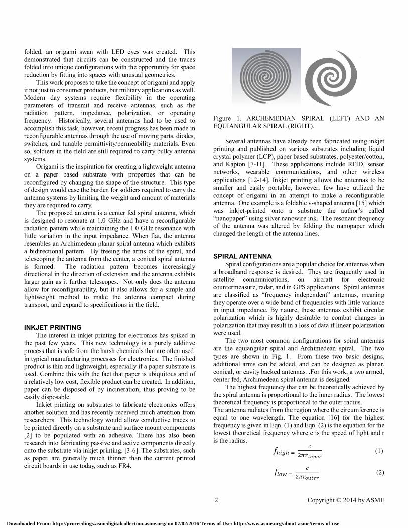
Figure 1. ARCHEMEDIAN SPIRAL (LEFT) AND AN
EQUIANGULAR SPIRAL (RIGHT).
Several antennas have already been fabricated using inkjet
printing and published on various substrates including liquid
crystal polymer (LCP), paper based substrates, polyester/cotton,
and Kapton [7-11]. These applications include RFID, sensor
networks, wearable communications, and other wireless
applications [12-14]. Inkjet printing allows the antennas to be
smaller and easily portable, however, few have utilized the
concept of origami in an attempt to make a reconfigurable
antenna. One example is a foldable v-shaped antenna [15] which
was inkjet-printed onto a substrate the author’s called
“nanopaper” using silver nanowire ink. The resonant frequency of the antenna was altered by folding the nanopaper which
changed the length of the antenna lines.
SPIRAL ANTENNA Spiral configurations are a popular choice for antennas when
a broadband response is desired. They are frequently used in
satellite communications, on aircraft for electronic
countermeasure, radar, and in GPS applications. Spiral antennas
are classified as “frequency independent” antennas, meaning
they operate over a wide band of frequencies with little variance in input impedance. By nature, these antennas exhibit circular
polarization which is highly desirable to combat changes in
polarization that may result in a loss of data if linear polarization
were used.
The two most common configurations for spiral antennas
are the equiangular spiral and Archimedean spiral. The two
types are shown in Fig. 1. From these two basic designs,
additional arms can be added, and can be designed as planar,
conical, or cavity backed antennas. .For this work, a two armed,
center fed, Archimedean spiral antenna is designed.
The highest frequency that can be theoretically achieved by
the spiral antenna is proportional to the inner radius. The lowest theoretical frequency is proportional to the outer radius.
The antenna radiates from the region where the circumference is
equal to one wavelength. The equation [16] for the highest
frequency is given in Eqn. (1) and Eqn. (2) is the equation for the
lowest theoretical frequency where c is the speed of light and r
is the radius.
𝑓ℎ𝑖𝑔ℎ = 𝑐
2𝜋𝑟𝑖𝑛𝑛𝑒𝑟 (1)
𝑓𝑙𝑜𝑤 = 𝑐
2𝜋𝑟𝑜𝑢𝑡𝑒𝑟 (2)
Downloaded From: http://proceedings.asmedigitalcollection.asme.org/ on 07/02/2016 Terms of Use: http://www.asme.org/about-asme/terms-of-use
3 Copyright © 2014 by ASME
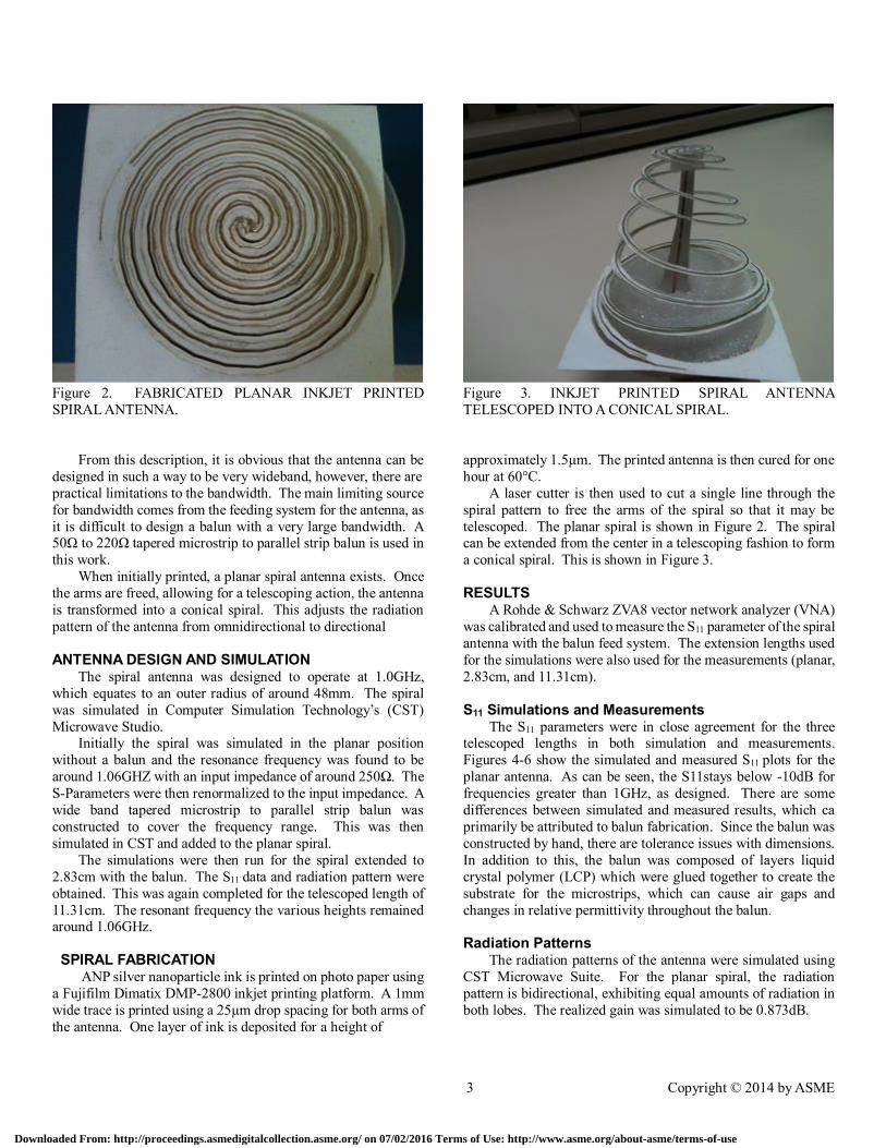
Figure 2. FABRICATED PLANAR INKJET PRINTED
SPIRAL ANTENNA.
From this description, it is obvious that the antenna can be
designed in such a way to be very wideband, however, there are
practical limitations to the bandwidth. The main limiting source
for bandwidth comes from the feeding system for the antenna, as
it is difficult to design a balun with a very large bandwidth. A 50Ω to 220Ω tapered microstrip to parallel strip balun is used in
this work.
When initially printed, a planar spiral antenna exists. Once
the arms are freed, allowing for a telescoping action, the antenna
is transformed into a conical spiral. This adjusts the radiation
pattern of the antenna from omnidirectional to directional
ANTENNA DESIGN AND SIMULATION The spiral antenna was designed to operate at 1.0GHz,
which equates to an outer radius of around 48mm. The spiral
was simulated in Computer Simulation Technology’s (CST)
Microwave Studio. Initially the spiral was simulated in the planar position
without a balun and the resonance frequency was found to be
around 1.06GHZ with an input impedance of around 250Ω. The
S-Parameters were then renormalized to the input impedance. A
wide band tapered microstrip to parallel strip balun was
constructed to cover the frequency range. This was then
simulated in CST and added to the planar spiral.
The simulations were then run for the spiral extended to
2.83cm with the balun. The S11 data and radiation pattern were
obtained. This was again completed for the telescoped length of
11.31cm. The resonant frequency the various heights remained around 1.06GHz.
SPIRAL FABRICATION ANP silver nanoparticle ink is printed on photo paper using
a Fujifilm Dimatix DMP-2800 inkjet printing platform. A 1mm
wide trace is printed using a 25µm drop spacing for both arms of
the antenna. One layer of ink is deposited for a height of
Figure 3. INKJET PRINTED SPIRAL ANTENNA
TELESCOPED INTO A CONICAL SPIRAL.
approximately 1.5µm. The printed antenna is then cured for one
hour at 60°C.
A laser cutter is then used to cut a single line through the
spiral pattern to free the arms of the spiral so that it may be
telescoped. The planar spiral is shown in Figure 2. The spiral can be extended from the center in a telescoping fashion to form
a conical spiral. This is shown in Figure 3.
RESULTS
A Rohde & Schwarz ZVA8 vector network analyzer (VNA)
was calibrated and used to measure the S11 parameter of the spiral
antenna with the balun feed system. The extension lengths used
for the simulations were also used for the measurements (planar,
2.83cm, and 11.31cm).
S11 Simulations and Measurements The S11 parameters were in close agreement for the three
telescoped lengths in both simulation and measurements.
Figures 4-6 show the simulated and measured S11 plots for the
planar antenna. As can be seen, the S11stays below -10dB for
frequencies greater than 1GHz, as designed. There are some
differences between simulated and measured results, which ca
primarily be attributed to balun fabrication. Since the balun was
constructed by hand, there are tolerance issues with dimensions.
In addition to this, the balun was composed of layers liquid
crystal polymer (LCP) which were glued together to create the
substrate for the microstrips, which can cause air gaps and
changes in relative permittivity throughout the balun.
Radiation Patterns The radiation patterns of the antenna were simulated using
CST Microwave Suite. For the planar spiral, the radiation
pattern is bidirectional, exhibiting equal amounts of radiation in
both lobes. The realized gain was simulated to be 0.873dB.
Downloaded From: http://proceedings.asmedigitalcollection.asme.org/ on 07/02/2016 Terms of Use: http://www.asme.org/about-asme/terms-of-use
4 Copyright © 2014 by ASME
Figure 4. SIMULATED VERSUS MEASURED S11 PLOTS
FOR PLANAR SPIRAL ANTENNA.
Figure 5. SIMULATED VERSUS MEASURED S11 PLOTS
FOR SPIRAL ANTENNA TELESCOPED 2.83CM.
Figure 6. SIMULATED VERSUS MEASURED S11 PLOTS
FOR SPIRAL ANTENNA TELESCOPED TO 11.31CM.
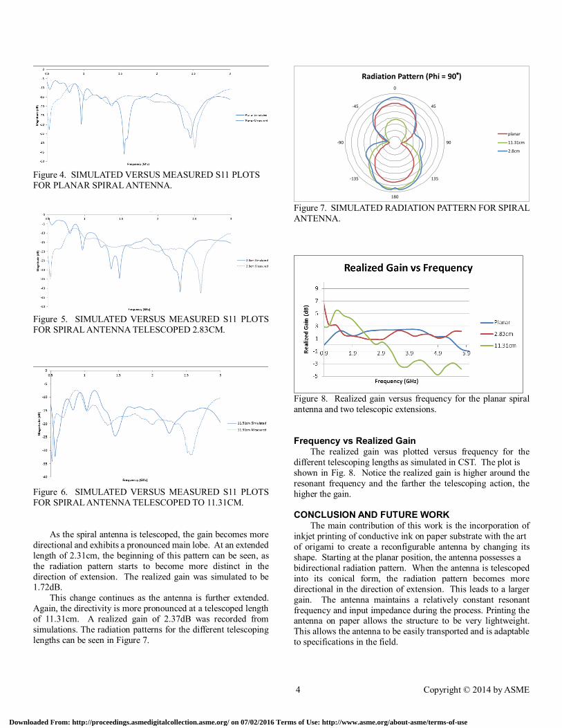
As the spiral antenna is telescoped, the gain becomes more
directional and exhibits a pronounced main lobe. At an extended
length of 2.31cm, the beginning of this pattern can be seen, as
the radiation pattern starts to become more distinct in the
direction of extension. The realized gain was simulated to be 1.72dB.
This change continues as the antenna is further extended.
Again, the directivity is more pronounced at a telescoped length
of 11.31cm. A realized gain of 2.37dB was recorded from
simulations. The radiation patterns for the different telescoping
lengths can be seen in Figure 7.
Figure 7. SIMULATED RADIATION PATTERN FOR SPIRAL
ANTENNA.
Figure 8. Realized gain versus frequency for the planar spiral
antenna and two telescopic extensions.
Frequency vs Realized Gain The realized gain was plotted versus frequency for the
different telescoping lengths as simulated in CST. The plot is
shown in Fig. 8. Notice the realized gain is higher around the
resonant frequency and the farther the telescoping action, the
higher the gain.
CONCLUSION AND FUTURE WORK The main contribution of this work is the incorporation of
inkjet printing of conductive ink on paper substrate with the art
of origami to create a reconfigurable antenna by changing its
shape. Starting at the planar position, the antenna possesses a
bidirectional radiation pattern. When the antenna is telescoped
into its conical form, the radiation pattern becomes more
directional in the direction of extension. This leads to a larger
gain. The antenna maintains a relatively constant resonant
frequency and input impedance during the process. Printing the antenna on paper allows the structure to be very lightweight.
This allows the antenna to be easily transported and is adaptable
to specifications in the field.
0
45
90
135
180
-135
-90
-45
Radiation Pattern (Phi = 90 )
planar
11.31cm
2.8cm
Downloaded From: http://proceedings.asmedigitalcollection.asme.org/ on 07/02/2016 Terms of Use: http://www.asme.org/about-asme/terms-of-use

5 Copyright © 2014 by ASME
For the future of this work, implementing an actuating
system for reconfiguration would greatly simplify the shape
changing operation of the antenna. This would allow the
antenna to adapt to its requirements without a human operator
performing a manual telescoping procedure.
This antenna can also be designed for a wide range of frequencies, so it is adaptable to different frequency bands. This
is merely accomplished by changing the dimensions of the inner
and outer radii. Inkjet printing allows for relatively rapid
fabrication, so spiral antennas of various sizes can be quickly
constructed.
ACKNOWLEDGMENTS This material is based upon work supported by the National
Science Foundation-EFRI under Grant No: 2106CRU.
REFERENCES
[1] Siegel, A., Phillips, S. T., Dickey, M., Lu, N., Suo, Z. and
Whitesides, G., 2010.” Foldable Printed Circuit Boards on
Paper Substrates”. Advanced Functional Materials, 20, pp. 28–
35.
[2] Kawahara, Y., Hodges, S., Cook, B.S., Zhang, C., Abowd,
G.D., 2013, “Instant Inkjet Circuits: Lab-based Inkjet Printing
to Support Rapid Prototyping of Ubicomp Devices,” Proc. Of
the 2013 ACM International Joint Conference on Pervasive
and Ubiquitous Computing, ACM. New York, NY, pp. 363-
372.
[3] Ko, S., Chung, J., Pan, H., Grigoropoulos, C., Poulikakos,
D., 2007. “Fabrication of Multilayer Passive and Active
Electric
Components on Polymer Using Inkjet Printing and Low
Temperature Laser Processing”. Sensors and Actuators A:
Physical, 134(1), February, pp. 161-168.
[4] Cook, B., Cooper, J., Tentzeris, M., 2013. "Multi-Layer RF
Capacitors on Flexible Substrates Utilizing Inkjet Printed
Dielectric Polymers," Microwave and Wireless Components
Letters, IEEE, 23(7), July, pp. 353-355.
[5] Kang,B., Lee, C., Oh, J., 2012. “All-Inkjet-Printed
Electrical Components and Circuit Fabrication on a Plastic
Substrate”. Microelectronic Engineering, 97, September, pp.
251-254.
[6] Jung, S., Sou, A., Gili, E., Sirringhaus, H., 2013. “Inkjet-Printed Resistors with a Wide Resistance Range for Printed
Read-Only Memory Applications”. Organic Electronics, 14(3)
pp. 699-702.
[7] Sangkil Kim, Tentzeris, M.M., Guiping J., Nikolaou, S.,
2012. "Inkjet printed ultra wideband spiral antenna using
integrated balun on liquid crystal polymer (LCP)". Antennas
and Propagation Society International Symposium (APSURSI).
pp.1-2, 8-14
[8] Maza, A.R.; Cook, B.; Jabbour, G.; Shamim, A., 2012.
"Paper-based inkjet-printed ultra-wideband fractal antennas".
Microwaves, Antennas & Propagation, IET. 6(12) pp.1366-
1373.
[9] Li Y., Rongwei Z. Staiculescu, D.; Wong, C., Tentzeris, M.
2009. "A Novel Conformal RFID-Enabled Module Utilizing
Inkjet-Printed Antennas and Carbon Nanotubes for Gas-
Detection Applications," Antennas and Wireless Propagation
Letters, IEEE, (8), pp.653-656.
[10] Whittow, W., Chauraya, A., Vardaxoglou, J., Li, Y.,
Torah, R., Yang, K., Beeby, S., Tudor, J., 2014. "Inkjet-Printed
Microstrip Patch Antennas Realized on Textile for Wearable
Applications". Antennas and Wireless Propagation Letters,
IEEE, 13, pp.71-74.
[11] Subbaraman, H., Pham, D., Xiaochuan X, Chen, M.,
Hosseini, A., Xuejun L, Chen, R., 2013. "Inkjet-Printed Two-
Dimensional Phased-Array Antenna on a Flexible Substrate".
Antennas and Wireless Propagation Letters, IEEE, 12, pp.170-
173.
[12] Rida, A., Yang, L., Vyas, R.; Tentzeris, M.M., 2009.
"Conductive Inkjet-Printed Antennas on Flexible Low-Cost
Paper-Based Substrates for RFID and WSN Applications".
Antennas and Propagation Magazine, IEEE, 51(3), June,
pp.13-23.
[13] Chauraya, A., Whittow, W., Vardaxoglou, J., Yi L., Torah,
R., Kai Y., Beeby, S., Tudor, J., 2013. "Inkjet Printed Dipole
Antennas on Textiles for Wearable
Communications," Microwaves, Antennas & Propagation, IET,
7(9), pp.760-767.
[14] Abutarboush, H., Shamim, A., “Paper-Based Inkjet-
Printed Tri-Band U-Slot Monopole Antenna for Wireless
Applications.” Antennas and Wireless Propagation Letter,
IEEE, 11, pp. 1234-1237.
[15] Nogi, M., Komoda, N., Otsuka, K., Suganuma, K., 2013.
“Foldable Nanopaper Antennas for Origami Electronics”.
Nanoscale, 10(5), pp. 4395-4399.
[16] Caswell, E., 2001. “Design and Analysis of Star Spiral
with Application to Wideband Arrays with Variable Element
Sizes”. PhD Thesis, Virginia Polytechnic Institute and State
University, Blacksburg, VA, December. See also URL
http://www.vt.edu
Downloaded From: http://proceedings.asmedigitalcollection.asme.org/ on 07/02/2016 Terms of Use: http://www.asme.org/about-asme/terms-of-use