
An Online Ballistics Imaging System for Firearm Identification
6
Edith Cowan University Research Online ECU Publications Pre. 2011 2010 An Online Ballistics Imaging System for Firearm Identification Zhihu Huang Edith Cowan University Jinsong Leng Edith Cowan University 10.1109/ICSPS.2010.5555219 is article was originally published as: Huang, Z. , & Leng, J. (2010). An online ballistics imaging system for firearm identification. Proceedings of 2010 2nd International Conference on Signal Processing Systems (ICSPS). (pp. 68-72). . Dalian, China. IEEE. Original article available here © 2010 IEEE. Personal use of this material is permied. Permission from IEEE must be obtained for all other uses, in any current or future media, including reprinting/republishing this material for advertising or promotional purposes, creating new collective works, for resale or redistribution to servers or lists, or reuse of any copyrighted component of this work in other works. is Conference Proceeding is posted at Research Online. hps://ro.ecu.edu.au/ecuworks/6348
Transcript of An Online Ballistics Imaging System for Firearm Identification
Edith Cowan UniversityResearch Online
ECU Publications Pre. 2011
2010
An Online Ballistics Imaging System for FirearmIdentificationZhihu HuangEdith Cowan University
Jinsong LengEdith Cowan University
10.1109/ICSPS.2010.5555219This article was originally published as: Huang, Z. , & Leng, J. (2010). An online ballistics imaging system for firearm identification. Proceedings of2010 2nd International Conference on Signal Processing Systems (ICSPS). (pp. 68-72). . Dalian, China. IEEE. Original article available here© 2010 IEEE. Personal use of this material is permitted. Permission from IEEE must be obtained for all other uses, in any current or future media,including reprinting/republishing this material for advertising or promotional purposes, creating new collective works, for resale or redistribution toservers or lists, or reuse of any copyrighted component of this work in other works.This Conference Proceeding is posted at Research Online.https://ro.ecu.edu.au/ecuworks/6348
AN ONLINE BALLISTICS IMAGING SYSTEM FOR FIREARM IDENTIFICATION
Zhihu Huang School of Computer and Security Science, Edith Cowan University
Chongqing Radio & TV University, ChongQing, China
Jinsong Leng School of Computer
and Security Science, Edith Cowan University, Australia
Abstract—Since the traditional ballistics imaging system is dependent upon the expertise and experience of end-user, an intelligent ballistics imaging system is highly demanded to overcome the drawbacks of traditional techniques. This paper aims to develop a novel ballistics imaging system so as to combine the traditional functions with new features such as the line-scan image module, the characteristics extraction module, and the intelligent image processing module. With the help of these features, the new system can identify firearm more efficiently and effectively than the traditional techniques.
Keywords- Ballistics Software System, Firearm Identification, Image Processing
I. INTRODUCTION The analysis of marks on the cartridge case and projectile
of a fired bullet is very important to identify the firearm from which the bullet is discharged [1, 2]. When a firearm is loaded and fired, the characteristic marks are produced on the cartridge case and projectile. These marks are important forensic evidences for identifying the suspicious firearm. Over thirty different features within theses marks can be referred as a ‘fingerprint’ for ballistics recognition [3]. Since each firearm owns its unique toolmarks [4, 5], it is possible to identify both the type and model of a firearm and each individual weapon effectively as human fingerprint identifi-cation.
Several commercial or testing ballistics imaging systems have been developed by organizations or researchers for decades [6-9]. Integrated Ballistics Identification System (IBIS) [9] is an international ballistics imaging system which has been widely used in many countries. Another commer-cial system called “Bulletproof” was developed by a Cana-dian company named Walsh Automation, which can acquire and store images of projectiles and cartridge cases by searching its image database for particular striations on pro-jectiles and cartridge cases. However, it is required to match the impressed markings or striations on the projectiles and cartridge cases by end-user. This kind of limitation makes the system very difficult to use. The firearm identification system called Fireball [8] was developed by Edith Cowan University in 1995, and it has been used by Australia Police Services for identifying, storing, and retrieving the images of projectiles and cartridge cases. The major limitation of Fire-ball is that the shape and position are tuned manually and thus the precision of comparisons relies on the expertise and
experience of the end-user. In summary, the major draw-backs of the existing systems are outlined as follows: Firstly, the identification of firearm strongly depends upon the end-user due to the lack of intelligent image processing tech-niques; Secondly, the image contrast of cartridge cases and projectiles is not good due to the difficulty in finding a suit-able illuminator; Finally, the lack of online image processing, retrieving and identification does not meet the demand of end-user. Therefore, the existing systems are required fur-ther improvement and development.
The automatic ballistics imaging system mainly includes two components: the acquisition and the correlation compo-nents [10]. The acquisition component includes capturing of cartridge cases and projectiles and extracting their features in order to make them analyzable. The correlation compo-nents are responsible for comparing the features and orga-nizing the results for the user’s inspection. The following functions should be involved in ballistics imaging system [11]:
• Evaluate the degree of similarity between two sets of features;
• Organize the results in some convenient way if more than two bullets are involved in a compari-son.
• Provide the user with tools to verify the results obtained by the correlation algorithms.
The paper introduces the development of a novel ballis-tics imaging system for firearm identification. The system can capture, store, analyze and retrieve the digital images of cartridge cases and projectiles. The major contributions of the system are summarized as follows. Firstly, an Online Ballistics Imaging System (OBIS) has been developed and implemented; Secondly, OBIS provides an efficient platform for computerizing ballistics images; Thirdly, the precision of identification can also be improved due to the use of artifi-cial intelligent techniques; Finally, the online system is con-venient for end-user and is also independent on the client computer.
The rest of the paper is organized as follows: Section II gives an introduction to firearm identification. In Section III, we illustrate the ballistics imaging system. An intelligent cartridge case segmentation algorithm is described in Sec-tion IV. Section V concludes this paper.
II. FIREARM IDENTIFICATION The aim of firearm identification is to provide a link be-
tween the suspect firearm and the forensic ballistics speci-
2010 2nd International Conference on Signal Processing Systems (ICSPS)
V2-68 978-1-4244-6891-1/$26.00 2010 IEEEC

mens based on the depressions, scratches and markings on the fired cartridge cases and projectiles. The various marks are called ‘toolmark’ that is unique to itself [5]. In this re-gard, we are able to identify the suspect firearm by toolmark left on ballistics specimens.
Firearm identification mainly includes the following steps [12]:
• Generate a test specimen by the crime scene fire-arm;
• Find and record the characteristic marks on the cartridge case and projectile;
• Extract and investigate the features of the charac-teristic marks;
• Compare the marks between the test specimen and the crime scene specimen;
• Assess the comparison between the test and crime scene specimen.
• Store the characteristic marks on the cartridge cases and projectiles for further comparison.
TABLE I. CHARACTERISTICS OF BALLISTICS SPECIMEN
Object Class characteristics Individual characteristics
Cartridge Case
Caliber Position of firing pin
Position of extractor mark Position of ejector mark
Breach or bolt impression
Striations of firing pin impression
Projectile
Caliber Twist direction of rifling
Land mark width Groove mark width
Degree of the rifling twist Number of lands
Number of grooves
Striations of groove
impressions
Charchman divided the characteristics of toolmark on
ballistics specimens into three major categories [13]: • “C” type characteristics were defined as class
characteristics; • “A” type characteristics were defined as acciden-tal
characteristics, which are individual character-istics; • “B” type characteristics were defined as broach
series characteristics, with B1 and B2 subclasses that occur on the edges of land impressions.
Generally, Firearm identification is concerned with two types of characteristics, i.e. class characteristics (C type) and individual characteristics (A type). While broach series characteristic (B type) is only applied in particular types of rifles. Class characteristics are useful in determining what brand of firearm was used, but not helpful in identifying an individual firearm. Individual characteristics can directly match a bullet to a firearm. That is, the match between indi-vidual characteristics and a bullet can ensure that one certain firearm was the only firearm that could have fired the bullet. These characteristics are detailed in Table I.
III. BALLISTICS IMAGING SYSTEM Due to the drawbacks of workstation system including
low data sharing and security, expensive cost of installation and maintenance, inconvenient application environment etc, we developed an Online Ballistics Imaging System based upon Browse-Server (BS) structure. Fig. 1 describes the structure of the system. With internet access and a web browser, the user can access OBIS anywhere and anytime.
Fig. 1 System structure of OBIS
OBIS not only considers the traditional functions including image capturing, storing, analyzing and retrieving but also provides some intelligent image processing functions. The new function modules of OBIS include the image acquisition module, the characteristic extraction module, the firearm identification module, and the intelligent image processing module.
A. Image acquisition The digital image acquisition of cartridge case and
projectile focuses on the following issues: how to choose illuminator to acquire high quality digital images; how to unfold the surface of cylindrical projectile into a 2D planar image in order to facilitate identification.
As indicated by Smith [8], the illuminator must be in-stalled at an incident angle of greater than 45 degrees from the illuminator to the plane of the head of the cartridge case in order to produce high contrast of images. Illuminator from such angles can produce better shadow cast of the peaks and ridges of striations. The high quality of shadow cast makes discernible features for the identification process. According to Smith guideline, we find that the lager or smaller incident angle will decrease the quality of images, and the ‘good’ incident angle is about 50º. Although the point source illu-minator can produce better shadow cast, the shadow cast of the image may vary with the rotational position of the car-tridge case about its central axis. Since the shadow cast of the image is invariant in LED ring-light illuminator, the LED ring-light illuminator is considered. Fig. 2 shows the high contrast image of head of cartridge case using LED ring-light illuminator.
The cylindrical shapes of ballistics projectiles (displayed in Fig. 3(a)) are inherently difficult to identify using tradi-tional incident light microscope. Maintaining the quality of image is very difficult because of loss of focus as the ballis-tics projectile translated and rotated. To resolve the issue, the line-scan imaging technique [14] is employed by rotating the cylindrical projectile and taking corresponding image, then combining these images into one image. Thus, the sur-face
2010 2nd International Conference on Signal Processing Systems (ICSPS)
V2-69
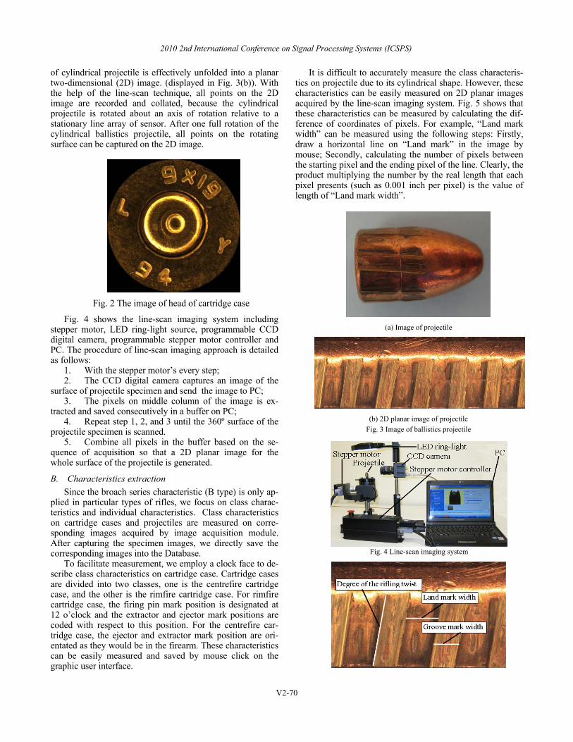
of cylindrical projectile is effectively unfolded into a planar two-dimensional (2D) image. (displayed in Fig. 3(b)). With the help of the line-scan technique, all points on the 2D image are recorded and collated, because the cylindrical projectile is rotated about an axis of rotation relative to a stationary line array of sensor. After one full rotation of the cylindrical ballistics projectile, all points on the rotating surface can be captured on the 2D image.
Fig. 2 The image of head of cartridge case
Fig. 4 shows the line-scan imaging system including stepper motor, LED ring-light source, programmable CCD digital camera, programmable stepper motor controller and PC. The procedure of line-scan imaging approach is detailed as follows:
1. With the stepper motor’s every step; 2. The CCD digital camera captures an image of the
surface of projectile specimen and send the image to PC; 3. The pixels on middle column of the image is ex-
tracted and saved consecutively in a buffer on PC; 4. Repeat step 1, 2, and 3 until the 360º surface of the
projectile specimen is scanned. 5. Combine all pixels in the buffer based on the se-
quence of acquisition so that a 2D planar image for the whole surface of the projectile is generated.
B. Characteristics extraction Since the broach series characteristic (B type) is only ap-
plied in particular types of rifles, we focus on class charac-teristics and individual characteristics. Class characteristics on cartridge cases and projectiles are measured on corre-sponding images acquired by image acquisition module. After capturing the specimen images, we directly save the corresponding images into the Database.
To facilitate measurement, we employ a clock face to de-scribe class characteristics on cartridge case. Cartridge cases are divided into two classes, one is the centrefire cartridge case, and the other is the rimfire cartridge case. For rimfire cartridge case, the firing pin mark position is designated at 12 o’clock and the extractor and ejector mark positions are coded with respect to this position. For the centrefire car-tridge case, the ejector and extractor mark position are ori-entated as they would be in the firearm. These characteristics can be easily measured and saved by mouse click on the graphic user interface.
It is difficult to accurately measure the class characteris-tics on projectile due to its cylindrical shape. However, these characteristics can be easily measured on 2D planar images acquired by the line-scan imaging system. Fig. 5 shows that these characteristics can be measured by calculating the dif-ference of coordinates of pixels. For example, “Land mark width” can be measured using the following steps: Firstly, draw a horizontal line on “Land mark” in the image by mouse; Secondly, calculating the number of pixels between the starting pixel and the ending pixel of the line. Clearly, the product multiplying the number by the real length that each pixel presents (such as 0.001 inch per pixel) is the value of length of “Land mark width”.
(a) Image of projectile
(b) 2D planar image of projectile Fig. 3 Image of ballistics projectile
Fig. 4 Line-scan imaging system
2010 2nd International Conference on Signal Processing Systems (ICSPS)
V2-70

Fig. 5 Characteristics measurement on 2D image
C. Firearm Identification In our system, firearm identification includes two steps:
one is to generate the short list of suspect firearm by searching class characteristics saved in database. The other is to make sure the unique suspect firearm from the short list by com-paring their high resolution images in detail manually.
After the short list is generated, various image techniques are provided to further compare these images. Benefit from these image techniques, it is easy to find the suspect firearm. These techniques are listed as follows:
• Freely zoom, translate and rotate images; • Transparentize and overlap images; • Add or remove “image mask” including grid mask,
clock face mask. Fig. 6 shows the transparent visualization for image
comparison. Fig. 6(a) shows two cartridge cases with differ-ent orientation. In Fig. 6(b), the left image illustrates the result directly transparentized and overlapped the two im-ages shown in Fig. 6(a), and the right image shows the result rotated the left image in Fig 6(a), and then transparentized and overlapped the two images. In Fig. 6(c), the left car-tridge cased is rotated to the same orientation as the right one, and then compared with the right one in details based on “grid mask”.
IV. INTELLIGENT SEGMENTATION OF CARTRIDGE CASE The segmentation of cartridge case from the input image
(displayed in Fig. 6(a)) is of paramount importance for fire-arm identification. However, the satisfactory result cannot be achieved using threshold-based methods because of the heavy shadow in the input image. To acquire the satisfactory segmented image of cartridge case, a novel approach based on color invariant properties [15] and geometrical shape of cartridge case is proposed. The method is composed of two steps. That is, remove the background and shadows using color invariant properties; detect and segment the circular cartridge case using Hough transform [16].
A. Remove background and shadows The color invariant properties are employed to remove
the background and shadows. Color invariants are function which describes the color configuration of each pixel on images discounting shadows, and highlights. These features are demonstrated to be invariant to a change in the imaging conditions including viewing direction, object’s surface ori-entation and illumination. Color invariants features are ac-quired by RGB using the following equations:
),(),,(max(),(arctan),(1
yxByxGyxRyxC =
),(),,(max(),(arctan),(2
yxByxRyxGyxC =
),(),,(max(),(arctan),(3
yxGyxRyxByxC =
where, R(x, y), G(x, y), and B(x, y) respectively repre-sent the red, green and blue components of a pixel in a im-age, while the C1(x, y), C2(x, y) and C3(x, y) represent cor-responding color invariants.
The procedure to remove background and shadows is detailed as follows:
(a) Two original cartridge cases
(b) Left: directly transparentize and overlap, Right: rotated, then
transparentize and overlap.
(c) Rotating left cartridge case and comparing with the right one
based on “grid mask”. Fig. 6 Comparison of cartridge case
1. Select a background whose values of color invari-ants do not overlap the values of cartridge case. It is well known that most cartridge cases are made by brass. Therefore, they have similar values of color invariants. In our research, the range of color invariants for cartridge cases is , the color with R=54, G=12, B=170 is selected as background. Its color invariants is C1= 0.31, C2=0.07, C3=1.26. Evidently, the values of color invariant for background are far from the ones of cartridge cases.
2. Capture the image of cartridge case based on the background selected in step 1.
2010 2nd International Conference on Signal Processing Systems (ICSPS)
V2-71

3. Remove the pixels whose color invariants near to the values of background. Thus, the background and shadows are removed.
Fig. 7(a) shows the input image. The result removed the background and shadows is shown in Fig. 7(b).
(a) (b)
Fig. 7 Remove the background and shadows. (a) Input image, (b) Result removed background and shadows
(a) (b)
(c) (d)
Fig. 8 Segmentation of cartridge case. (a) Binarized image, (b) Edged image, (c) Circular edge between cartridge case and background, (d)
Segmented cartridge case.
B. Segment cartridge case Although the major background and shadows can be re-
moved using the methods described in the Section 4.1, the image of cartridge case needs further refinement for identifi-cation. A few noise pixels belong to the background are dif-ficult to be removed, in addition, the borders of the cartridge case are not smooth. To address these issues and segment cartridge case accurately, the Hough transform [16] is em-ployed for automatic circle detection. The method segment-ing cartridge case includes the following steps:
1. Binarize the image displayed in Fig. 6(b) using Otsu algorithm;
2. Detect the edges to the binarized image using So-bel operator;
3. Detect the Circular edge between the cartridge case and background in the edged image using Hough transform;
4. Segment the cartridge case based upon the de-tected circular edge from the input image.
Fig. 8 illustrates the process to segment cartridge case based on the result in Fig. 7(b).
V. CONCLUSION This paper summaries the features of the online ballistics
imaging system for firearm identification which not only involves traditional functions including image capturing, storing, analyzing and retrieving but also intelligent image processing. The system can identify firearm more efficiently and effectively due to the new functions including the line-scan imaging system and intelligent image processing. Fu-ture work includes researching the criterion for extracting individual characteristics and increasing more functions of intelligent analysis for firearm identification.
REFERENCES [1] Dongguang Li, "Ballistics Projectile Image Analysis for Firearm
Identification," IEEE Transaction on Image Proc-essing, vol. 15, pp. 2857-2865, 2006.
[2] R. Saferstein (ED), "Forensic Science Handbook," Vol-ume 2. Englewood Cliffs: Prentice Hall, 1988.
[3] G.Burrard, "Identification of Firearms and Forensic Bal-listics," London, U.K:Herbert Jenkins, 1951.
[4] A. Biasotti and J. Murdock, "Criteria for identification or State of the Art of Firearm and Toolmark Identification," AFTE Journal, vol. 16, pp. 16-34, 1984.
[5] A. Schwartz, "A Systemic Challenge to the Reliability and Admissibility of Firearms and Toolmark Identification," The Columbia Science and Technology Law Review, pp. 1-42, 2005.
[6] Chenyuan Kou, Cheng-Tan Tung, et al., "FISOFM: Fire-arms Identification based on SOFM model of Neural Net-work," in Security Technology, 1994, Proceedings. Institute of Electrical and Electronics Engineers 28th Annual 1994 International Carnahan Conference, Albuquerque, NM, USA, 1994, pp. 120-125.
[7] C.L. Smith, Robinson. M, et al., "Linescan Imaging for the positive identification of ballistics Specimens," in IEEE 34th Annual 2000 International Carnahan Conference, Ot-tawa, Ont., Canada, 2000, pp. 269-275.
[8] C. L. Smith, "Fireball: a forensic ballistics imaging sys-tem," in The Institute of Electrical and Electronics Engi-neers 31st Annual 1997 International Carnahan Conference, Canberra, 1997, pp. 64-70.
[9] IBIS (Integrated Ballistics Identification System). http://www.fti-ibis.com/.
[10] Natalie G. Carpenter, "An Examination Of A Three-Dimensional Automated Firearms Evidence Comparison," in Department of Criminology College of Arts and Sciences University of South Florida, April 8, 2004.
[11] Bachrach B., "Development of a 3D-based automated firearms evidence comparison system," Journal of Forensic Sciences, vol. 47, pp. 1-12, 2002.
[12] C. L. Smith, "Multi-dimensional cluster analysis of class characteristics for ballistics specimen identification," in Security Technology, 2001 IEEE 35th International Carnahan Conference, London, UK, 2001, pp. 115-121.
[13] J. Churchman, "The reproduction of characteristics in signatures of Cooey rifles," RCMP Gazette, vol. 11, pp. 133-140, 1949.
[14] A. Zographos, M. Robinson, et al., "Ballistics Identifi-cation Using Line-Scan Imaging Techniques, in Security Technology, 1997, Proceedings. The Institute of Electrical and Electronics Engineers 31st Annual 1997 International Carnahan Conference, Canberra, ACT, Australia, " 1997, pp. 82-87.
[15] T. Gevers, "Color-based object recognition," Pattern Recognition, vol. 32, pp. 453-464, 1999.
[16] R. O. Duda and P.E. Hart, "Use of the Hough Trans-formation to Detect Lines and Curves in Pictures," Comm. ACM, vol. 15, pp. 11-15, 1972.
2010 2nd International Conference on Signal Processing Systems (ICSPS)
V2-72