An NS-3 Implementation and Experimental Performance ...
31
International Journal of Environmental Research and Public Health Article An NS-3 Implementation and Experimental Performance Analysis of IEEE 802.15.6 Standard under Different Deployment Scenarios Beom-Su Kim 1 , Tae-Eung Sung 2 and Ki-Il Kim 1, * 1 Department of Computer Science and Engineering, Chungnam National University, Daejeon 34134, Korea; [email protected] 2 Department of Computer and Telecommunications Engineering, Yonsei University, Wonju 26493, Korea; [email protected] * Correspondence: [email protected]; Tel.: +82-42-821-6856 Received: 3 April 2020; Accepted: 29 May 2020; Published: 4 June 2020 Abstract: Various simulation studies for wireless body area networks (WBANs) based on the IEEE 802.15.6 standard have recently been carried out. However, most of these studies have applied a simplified model without using any major components specific to IEEE 802.15.6, such as connection-oriented link allocations, inter-WBAN interference mitigation, or a two-hop star topology extension. Thus, such deficiencies can lead to an inaccurate performance analysis. To solve these problems, in this study, we conducted a comprehensive review of the major components of the IEEE 802.15.6 standard and herein present modeling strategies for implementing IEEE 802.15.6 MAC on an NS-3 simulator. In addition, we configured realistic network scenarios for a performance evaluation in terms of throughput, average delay, and power consumption. The simulation results prove that our simulation system provides acceptable levels of performance for various types of medical applications, and can support the latest research topics regarding the dynamic resource allocation, inter-WBAN interference mitigation, and intra-WBAN routing. Keywords: wireless body area networks (WBAN); IEEE 802.15.6; NS-3 implementation 1. Introduction IEEE 802.15.6 [1] is a new wireless communication standard for wireless body area networks (WBANs). WBANs are mainly used for monitoring physical conditions, such as the heart rate and blood pressure, for recording electrocardiograms (ECGs) and electroencephalograms (EEGs), and for forwarding physical data to a hub. The purpose of IEEE 802.15.6 is to provide an international standard for a short-range, low power, and reliable communication in or around the human body. This contrasts with other approaches, such as low-rate wireless personal area networks (WPANs), based on IEEE 802.15.4 [2], which require more power and bandwidth. Thus, research into WBANs must thoroughly comply with the IEEE 802.15.6 standard to meet its strict requirements and regulations. The latest research topics based on the IEEE 802.15.6 standard can be classified into three categories. The first is a study on dynamic resource allocation or transmission scheduling scheme for intra-WBAN communications. Technically, designing such a intra-WBAN resource allocation or transmission scheduling scheme is quite challenging due to the following reasons: (i) unpredictable movements of the human body and changes in posture can significantly degrade the network performance; and (ii) available resources are very limited and the battery cannot be replaced because the medical sensors are attached in or on the human body; and (iii) significant amounts of RF energy (i.e., specific absorption rate (SAR) is the rate at which the human body absorbs radio frequency (RF) radiation) can increase the Int. J. Environ. Res. Public Health 2020, 17, 4007; doi:10.3390/ijerph17114007 www.mdpi.com/journal/ijerph
Transcript of An NS-3 Implementation and Experimental Performance ...

International Journal of
Environmental Research
and Public Health
Article
An NS-3 Implementation and ExperimentalPerformance Analysis of IEEE 802.15.6 Standardunder Different Deployment Scenarios
Beom-Su Kim 1, Tae-Eung Sung 2 and Ki-Il Kim 1,*1 Department of Computer Science and Engineering, Chungnam National University, Daejeon 34134, Korea;
[email protected] Department of Computer and Telecommunications Engineering, Yonsei University, Wonju 26493, Korea;
[email protected]* Correspondence: [email protected]; Tel.: +82-42-821-6856
Received: 3 April 2020; Accepted: 29 May 2020; Published: 4 June 2020�����������������
Abstract: Various simulation studies for wireless body area networks (WBANs) based on theIEEE 802.15.6 standard have recently been carried out. However, most of these studies haveapplied a simplified model without using any major components specific to IEEE 802.15.6, such asconnection-oriented link allocations, inter-WBAN interference mitigation, or a two-hop star topologyextension. Thus, such deficiencies can lead to an inaccurate performance analysis. To solve theseproblems, in this study, we conducted a comprehensive review of the major components of theIEEE 802.15.6 standard and herein present modeling strategies for implementing IEEE 802.15.6 MACon an NS-3 simulator. In addition, we configured realistic network scenarios for a performanceevaluation in terms of throughput, average delay, and power consumption. The simulation resultsprove that our simulation system provides acceptable levels of performance for various types ofmedical applications, and can support the latest research topics regarding the dynamic resourceallocation, inter-WBAN interference mitigation, and intra-WBAN routing.
Keywords: wireless body area networks (WBAN); IEEE 802.15.6; NS-3 implementation
1. Introduction
IEEE 802.15.6 [1] is a new wireless communication standard for wireless body area networks(WBANs). WBANs are mainly used for monitoring physical conditions, such as the heart rate andblood pressure, for recording electrocardiograms (ECGs) and electroencephalograms (EEGs), andfor forwarding physical data to a hub. The purpose of IEEE 802.15.6 is to provide an internationalstandard for a short-range, low power, and reliable communication in or around the human body. Thiscontrasts with other approaches, such as low-rate wireless personal area networks (WPANs), basedon IEEE 802.15.4 [2], which require more power and bandwidth. Thus, research into WBANs mustthoroughly comply with the IEEE 802.15.6 standard to meet its strict requirements and regulations.
The latest research topics based on the IEEE 802.15.6 standard can be classified into three categories.The first is a study on dynamic resource allocation or transmission scheduling scheme for intra-WBANcommunications. Technically, designing such a intra-WBAN resource allocation or transmissionscheduling scheme is quite challenging due to the following reasons: (i) unpredictable movements ofthe human body and changes in posture can significantly degrade the network performance; and (ii)available resources are very limited and the battery cannot be replaced because the medical sensors areattached in or on the human body; and (iii) significant amounts of RF energy (i.e., specific absorptionrate (SAR) is the rate at which the human body absorbs radio frequency (RF) radiation) can increase the
Int. J. Environ. Res. Public Health 2020, 17, 4007; doi:10.3390/ijerph17114007 www.mdpi.com/journal/ijerph

Int. J. Environ. Res. Public Health 2020, 17, 4007 2 of 31
body temperature and cause tissue damage. For example, if a channel is assigned to a node that is likelyto fail transmission, then resources will be wasted. On the other hand, excessive resource allocationbiased to a specific node shortens network life and damages body tissue. That is, the resource allocationor transmission scheduling policy must consider effects on portable antennas, radiation pattern, andchanges in characteristics as a result of the body movement. The second is a study on channel sharingmechanism between adjacent BANs. As we enter an aging society, the data transmissions in the smallarea (e.g., a hospital) will be explosively increased in the near future. However, the existing channelsharing mechanisms can hardly meet the requirements for e-health services in a wireless hospitalenvironment. The third is the study of intra-WBAN routing protocol. Although the WBAN topology isbasically based on a single-hop star topology, a number of routing schemes using body movementsare also being studied to optimize the transmission power or prevent the temperature rise of thehuman body.
As we described above, there are critical research challenges that need to be solved before thee-health monitoring system is applied to real life. To meet the aim of achieving a reliable medicalsystem, these restrictions should be addressed in advance through appropriate simulations. However,existing IEEE 802.15.6 simulation systems cannot support the aforementioned research topics becausethey provide a simplified network model without any major components specified in the IEEE 802.15.6standard such as connection-oriented resource allocations, inter-WBAN interference mitigation, ora two-hop star topology extension. As a result, the performance verification methods used in recentstudies are somewhat questionable, a common problem being the omission of the frame exchangeprocedure of the IEEE 802.15.6 MAC protocol (e.g., a MATLAB-based simulation), or non-compliancewith the MAC/PHY parameters defined in the IEEE 802.15.6 standard. For example, current WBANrouting protocols [3–5] do not follow the IEEE 802.15.6 MAC standard for a performance verification,or merely describe the concept of the proposed protocol. That is, they ignore the frame exchangesequence for a BAN configuration, transmission scheduling, and resource allocation. As a result, itis unlikely that their mechanism can be applied to real medical systems. In addition, current IEEE802.15.6 MAC studies [6–8] have evaluated their mechanisms based on the IEEE 802.15.4 standard.That is, the simulation results are unreliable unless some mechanisms for a resource allocation, channelusage agreement, inter-WBAN interference mitigation, and two-hop star topology extension specifiedin the IEEE 802.15.6 standard are reflected in their protocol design. In conclusion, their performanceverification methods cannot meet the medical constraints or communication regulations for certainmedical applications.
To meet the requirements of various medical applications and improve the reliability of thesimulation results, numerous simulation platforms for WBANs have been proposed. First, IEEE802.15.4 based WBAN simulation platforms have been proposed [9–12]. Their prototype systems arebased on a beacon mode with superframes. The superframe structure is divided into a contention accessperiod (CAP) and a contention free period (CFP). The authors constructed a single BAN consisting of ahub and several sensor nodes. To support a heterogeneous traffic flow, the hub can reserve one or moretime slots for a time-critical data application. The non-time-critical data are transmitted to the hubusing CSMA/CA. Although the IEEE 802.15.4 based simulation systems provide the useful functionsnecessary for node-to-hub communication, they cannot meet the specific requirements presented inthe IEEE 802.15.6 standard. For example, to provide a differentiated quality-of-service (QoS), the IEEE802.15.6 standard classifies traffic types into eight levels according to the user priorities, and usesthe values assigned to each level as a back-off counter for CSMA/CA. In addition, the IEEE 802.15.6standard provides complementary mechanisms to mitigate channel interference with neighboringBANs, such as beacon shifting, channel hopping, and active superframe interleaving, although most ofthem do not support these features.
To overcome the limitations of IEEE 802.15.4-based WBAN simulation platforms, more realisticWBAN simulation systems have been proposed [13–19]. In the simulation system, a WBAN consists ofheterogeneous nodes with different requirements. The authors modified the CSMA/CA algorithm
Int. J. Environ. Res. Public Health 2020, 17, 4007 3 of 31
based on the IEEE 802.15.6 standard to provide a user priority service. To build a more realisticsimulation system, they designed the PHY model according to the frequency band supported by theIEEE 802.15.6 standard and measured the performance using the modified CSMA/CA. In addition,numerical formulas were derived to evaluate the performance of the proposed system in terms ofits energy consumption, throughput, and delay. However, other access modes, such as a beaconmode with superframes and a non-beacon mode without superframes, are not provided, and thus itis difficult to verify the accurate performance under different WBAN scenarios. Moreover, realisticsimulations cannot be conducted because the channel model or propagation loss model applied to thesimulation system ignores the body shadowing or channel fading caused by human mobility.
To reflect non-ideal on-body channel characteristics for use in the simulation system, in [20–23],a simulation system is proposed for modeling an on-body channel and evaluating the performance ofWBAN transmission schemes. The authors defined a new propagation loss model and calculated thespecific reception sensitivity based on the position of the node pair. The proposed on-body channelmodels allow the simulation system to conduct a more realistic performance evaluation under variousWBAN scenarios. However, most of the scenarios define an on-body channel model for a singleWBAN without considering the channel interference caused by the surrounding environment. In otherwords, in a public area consisting of numerous local WBANs, such as a hospital, the WBAN systemshould provide an appropriate coexistence mechanism between neighboring WBANs. However, theproposed systems do not provide a channel interference mitigation mechanism between adjacentWBANs. In addition, they do not provide a set of communication functions required for a realisticWBAN simulation (e.g., a connection request frame or connection assignment frame exchange processfor the association between a hub and a node).
In summary, existing WBAN simulation systems cannot be used to conduct a realistic WBANsimulation under different network scenarios, nor do they support the current research trends inWBANs because they do not consider the following components specified in the IEEE 802.15.6standard. First, to send higher priority data, the IEEE 802.15.6 MAC provides a priority-basedrandom-access phase and managed access phase (MAP) in beacon mode with superframes. MAP isused to arrange unscheduled allocation intervals, scheduled allocation intervals, and improvisedpolling access intervals, and is necessary to support the QoS of emergency data or time critical data.In addition, MAP plays an important role in adaptive resource management in response to bodymovements. However, most WBAN simulation systems provide only a random-access phase for aframe transmission. Second, the existing simulation systems try to eliminate intra-WBAN interferenceusing CSMA/CA. Further, having smooth coexistence mechanisms with neighboring BANs isimportant to avoid inter-WBAN interference. That is, a WBAN simulation system should provide acomplementary mechanism to mitigate channel interference with neighboring WBANs. Third, existingsimulation systems assume a one-hop star topology for a network consisting of several sensor nodesconnected to a hub. In a one-hop star topology, the data frames between a hub and node are exchangeddirectly. However, to evaluate the routing protocols studied in WBANs, such as temperature-aware [24],energy-aware [25], and mobility-aware routing [26], an additional complementary mechanism (i.e.,two-hop star topology extension) should be provided in the simulation system.
To make the WBAN simulation platform closer to a practical WBAN system and support thecurrent research trends regarding WBANs, in this study, we review the major components of the IEEE802.15.6 standard and present modeling strategies for implementing the IEEE 802.15.6 MAC on anNS-3 simulator. In addition, we configure various simulation scenarios, such as a heterogeneous trafficflow, channel sharing between multi-WBANs, and a two-hop star network topology for a realisticperformance evaluation.
We can achieve the following benefits by accurately implementing the components specifiedin the IEEE 802.15.6 standard; (i) the accurate performance of the proposed system model can beevaluated in advance before we develop the actual WBAN prototype; and (ii) it is possible to determinewhether the proposed system model can meet the strict requirements of various medical applications
Int. J. Environ. Res. Public Health 2020, 17, 4007 4 of 31
(i.e., scalability) or whether it can be applied to actual medical systems (i.e., adaptability); and (iii)by providing a prototype for a WBAN, it is possible to design a specific system model with the newmodern technologies (e.g., blockchain, machine learning).
The main contributions of this paper are summarized below.
• We provide a comprehensive review of the major components of the IEEE 802.15.6 standard andpropose modeling strategies for implementing the IEEE 802.15.6 MAC on an NS-3 simulator.The proposed modeling strategies can also be useful when researchers build a wireless personalarea network system based on an NS-3 simulator.
• Unlike existing simulation systems for WBANs, we implement core mechanisms such as anassociation, connection-oriented link allocation, channel hopping mechanism, and a two-hop startopology extension. By using these mechanisms, our simulation system can support the latestresearch topics regarding the dynamic resource allocation/transmission scheduling, inter-WBANinterference mitigation, and intra-WBAN routing.
• To meet the aim of achieving a reliable health monitoring system, we model the necessarycomponents on an NS-3 simulator, including the PHY, MAC, error rate, propagation loss,on-body channel, energy, and human mobility models. In addition, we present specific networkconfigurations required for a realistic simulation. By providing a realistic simulation environment,it is possible to determine whether the proposed WBAN model can meet the strict requirements ofmedical applications.
• We evaluate the performance of the proposed simulation system under realistic WBAN scenariossuch as a heterogeneous traffic flow, channel sharing between multi-WBANs, and two-hop starnetwork topology. Such network scenarios make our simulation platform closer to that of apractical WBAN system and allow us to pre-determine whether the proposed WBAN system canbe applied to the real world before we develop the actual medical system.
• The IEEE 802.15.6 standard has already been optimized for a WBAN system, although there areadditional constraints that need be considered in the MAC protocol design. We present futurestudies that should be reflected in the WBAN system and introduce the lastest WBAN researchdomains where the proposed simulation system can be used.
The remainder of this paper is organized as follows. Section 2 describes previous related studies.In Section 3, the major components of IEEE 802.15.6 MAC are described. In Section 4, we describethe design strategies of IEEE 802.15.6 MAC on an NS-3 simulator. A performance evaluation is thendetailed in Section 6. Areas of future study and some concluding remarks are finally presented inSections 7 and 8, respectively.
2. Related Studies
To build a reliable health monitoring system, a WBAN communication technology needs toconsider not only the requirements of various medical applications, but also efficient resourcemanagement schemes and bio-effects that reflect the characteristics of the human body. Thus, theserestrictions need to be addressed in advance through appropriate simulations. As shown in Table 1,there are various simulation platforms that provide a realistic WBAN simulation environment aswell as useful frameworks such as OPNET, OMNET++, CANet, MATLAB and NS-3, however,most of them do not provide a specific prototype for a WBAN. In other words, if there are majorcomponents not supported by the simulation system, we cannot perform an accurate performanceevaluation. For example, if the simulation system does not support a two-hop star topologyextension, all intra-routing protocols cannot be simulated because the IEEE 802.15.6 MAC standardbasically considers one-hop transmission. Similarly, the resource allocation/transmission schedulingpolicy cannot be customized unless the simulation system supports the association mechanism(i.e., connection-oriented link allocation) between a hub and a node. In this section, we discussthe limitations of previous WBAN studies using the existing WBAN simulation systems.

Int. J. Environ. Res. Public Health 2020, 17, 4007 5 of 31
Table 1. Comparison of wireless body area network (WBAN) simulation systems.
SimulationPlatform
ChannelAccessMechanism
Association(ConnectionOrientedResourceAllocationMechanism)
MutualInterferenceMitigation(ChannelSharingMechanism)
QoS Support(HeterogeneousTraffic Flow)
RoutingSupport(Two-HopTopologyExtension)
C [9,12] CSMA/CA,GTS
N N N N
C++ [13,27] CSMA/CA,GTS
N N Y N
OMNET++[10]
CSMA/CA,GTS, Poll
N N N N
OPNET[11,14,15]
CSMA/CA N Y Y N
CANet [16] CSMA/CA N N Y N
MATLAB[28,29]
CSMA/CA N N Y N
NS-3 [17–19] CSMA/CA N N Y N
NS-3(Proposed)
CSMA/CA,GTS, Poll
Y Y Y Y
Since the IEEE 802.15.6 standard was first released, numerous researchers have adopted strategiesto modify or extend the IEEE 802.15.4 system and provide a BAN-specific simulation environment.C. Li et al. [9] conducted WBAN simulations based on an IEEE 802.15.4 system modeled in standard C.They constructed a single BAN consisting of a hub and sensor nodes. The proposed simulation systemuses beacon mode with superframes specified in the IEEE 802.15.4 standard to support heterogeneousWBAN traffic. The superframe structure is divided into CAP and CFP. The hub reserves one ormore time slots in CFP for a time-critical data transmission. CAP is used for a non-time-critical datatransmission. The same approach is used in [10]. In addition to applying the same superframe structure,their system provides a scheduled polling access phase using the OMNET++ and MiXim framework.M. Deylami et al. [11] provided an IEEE 802.15.4-based WBAN simulation system designed to mitigatethe harmful effects of the coexistence between neighboring BANs. They modeled the WBAN systemusing the IEEE 802.15.4 framework provided by the OPNET network modeler. In the proposed system,each BAN should exchange control messages with other local BANs to synchronize the order of thechannel usage. Y. Kim et al. [12] proposed an IEEE 802.15.4-based WBAN simulation system forbuilding a health monitoring system in a WBAN/WiFi coexistence environment, and developed a newdiscrete event-driven simulator to evaluate their adaptive load control algorithm. Their system followsthe superframe structure of the IEEE 802.15.4 standard.
Although an IEEE 802.15.4-based WBAN simulation system can cover the major issues of a bodyarea network, it has difficulty meeting the different requirements of medical applications such asthe throughput, delay, and power consumption. To provide a user-priority service according to themedical application, as an example, the IEEE 802.15.6 standard classifies traffic types into eight levelsaccording to the user priorities and uses the values assigned to each priority level as a back-off counterfor CSMA/CA. In addition, the resource allocation schemes and complementary mechanisms specifiedin the IEEE 802.15.6 standard are not supported.
To overcome the limitations of the existing IEEE 802.15.4-based WBAN simulation platforms,numerous WBAN-specific simulation systems based on the IEEE 802.15.6 standard have been proposed.To verify the performance of a WBAN-specific simulation system, S. Ullah et al. [13,27] constructeda WBAN system using standard C++. Their system measures the performance under maximum

Int. J. Environ. Res. Public Health 2020, 17, 4007 6 of 31
throughput and an average delay over the different frequency bands and data rates supported bythe IEEE 802.15.6 physical layer. However, the proposed system assumes that the channel conditionis perfect and that the bit error rate (BER) is zero. In addition, it provides only a priority-basedcontention access phase for a frame transmission. J. Y. Khan et al. [14] presented a specific WBANdesign technique for medical applications. They also reviewed the design issues of the WBANMAC protocol required for reducing the energy consumption. They then constructed a WBANsystem based on the CSMA/CA architecture and analyzed the performance of the patient monitoringapplications using the OPNET network modeler. However, their proposed system also assumesideal channel conditions and does not provide a flexible resource allocation scheme. L. Z. Kahsayet al. [15] constructed a WBAN-specific communication system using a user priority-based randomback-off scheme in a wireless hospital environment. The simulation system is built using the OPNETnetwork modeler. However, the proposed system offers limited communication functions andframeworks, which makes it difficult to evaluate the performance under various WBAN environments.H. Fourati et al. [16] proposed a WBAN system for the CANet e-health project. The CANet (CaneNetwork) project aims to implement a monitoring system for the elderly that can be used in everydaylife. Their system follows the superframe structure of the IEEE 802.15.6 standard and provides auser priority-based random-access phase (RAP). However, the superframe structure does not includescheduled access phases or polling access phases specified in the IEEE 802.15.6 standard. In addition,W. Yue et al. [17] constructed a WBAN simulation platform on an NS-3 simulator. Their systemconfigures a specific WBAN simulation scenario according to the practical application. In addition,they modify or implement some modules, such as a CSMA/CA module, PHY module, and MACmodule provided by the NS-3, based on the IEEE 802.15.6 standard. However, the proposed systemprovides only a random-access phase for the frame transmission and omits the functions necessary forresource management such as a connection-oriented link allocation. The same approach is used in [18],but similarly, the proposed prototype system provides only basic communication functions. That is,the proposed WBAN systems are designed for a single BAN, and thus complementary mechanismssuch as channel interference mitigation with adjacent BANs are not supported. X. Yuan et al. [19]constructed coexisting WBAN environments and evaluated the normalized throughput and averagedelay between coexisting WBANs based on the IEEE 802.15.6 CSMA/CA mechanism. However, theirsystem does not implement channel-sharing mechanisms such as beacon shifting, channel hopping, oractive superframe interleaving specified in the IEEE 802.15.6 standard. Finally, some research worksuch as [28] and introduced in [29] have been conducted to evaluate performance through MATLAB.
In summary, the existing WBAN-specific simulation systems commonly aim to providedifferentiated user priority services according to medical applications. To achieve this goal, mostof them modify the CSMA/CA algorithm based on the user priorities. However, they do notprovide other access modes, such as the beacon mode with superframes or non-beacon mode withoutsuperframes, and thus it is difficult to verify the accuracy of the performance under different WBANscenarios. In addition, the IEEE 802.15.6 standard provides complementary mechanisms to mitigatechannel interference with neighboring BANs, such as beacon shifting, channel hopping, and activesuperframe interleaving, but most of them do not support these features. Moreover, the proposedWBAN simulation systems assume a one-hop star topology for a network consisting of several sensornodes connected to a hub. That is, a two-hop star topology extension mode should be provided in thesimulation system to support the routing protocols being studied in the WBANs [24–26]. Moreover,realistic simulations cannot be conducted because the channel model or propagation loss model appliedto their simulation systems ignores the body shadowing or channel fading caused by human mobility.
To consider non-ideal on-body channel characteristics, WBAN-specific channel models andframeworks have been proposed [20–23]. In these studies, WBAN simulation systems are proposedfor modeling an on-body channel and evaluating the performance of WBAN transmission schemes.Their systems define a new propagation loss model and an on-body channel model based on theposition of the node pair. However, most of them define the channel models for a single BAN without

Int. J. Environ. Res. Public Health 2020, 17, 4007 7 of 31
considering the channel interference caused by the surrounding environment. In addition, they alsodo not provide various access phases required for realistic simulations such as scheduled access orimprovised polling access.
To deal with the aforementioned problems, we review the major components of the IEEE 802.15.6standard and present modeling strategies for implementing the IEEE 802.15.6 MAC on an NS-3simulator. In addition, we configure various simulation scenarios, such as a heterogeneous trafficflow, channel sharing between multi-WBANs, and two-hop star network topology for a realisticperformance evaluation. The major components of the IEEE 802.15.6 MAC layer are described in thefollowing section.
3. Major Components of IEEE 802.15.6 MAC Layer
The IEEE 802.15.6 standard provides significant flexibility to users by providing uniquemechanisms such as association, access mode, access phase, acknowledgment policy, two-hop startopology extension, and inter-WBAN interference mitigation. A network simulator based on the IEEE802.15.6 standard must implement the following components.
3.1. Association
A node sends a non-command management type frame to the hub to be assigned a one-octetnode identifier (NID) from the hub, and the hub responds with an NID (0x02-0xF5) in the recipientID field of the ACK message. After receiving an authorized NID from the hub, the node may receiveor transmit a message from a node or hub belonging to the same BAN. An association is a series ofprocesses used for constructing a local body area network between a hub and nodes and is essentialfor preventing inter-WBAN interference and communication with unauthorized nodes.
3.2. Access Mode
A hub should choose an appropriate access mode, based on the channel conditions, applicationrequirements, coexistence consideration, and policy regulations to reduce the risk of mutualinterference with other electronic devices or to save resources. As shown in Figures 1–3, a hub operatesin one of three access modes; beacon mode with superframes, non-beacon mode with superframes,and non-beacon mode without superframes. A hub operates in beacon mode, transmitting a beaconduring every beacon period (superframes), to enable time referenced allocations. By contrast, a huboperates in non-beacon mode with superframes if access to the medium in its BAN involves timereferencing, or without superframes if access to the medium in its BAN involves no time referencing.
Figure 1. Beacon mode with superframes.
Figure 2. Non-beacon mode with superframes.

Int. J. Environ. Res. Public Health 2020, 17, 4007 8 of 31
Figure 3. Non-beacon mode without superframes.
3.3. Access Phase
A hub organizes applicable access phases in each superframe, as illustrated in Figure 1. The hubshould place the access phases, i.e., exclusive access phase (EAP), random access phase (RAP),contention access phase (CAP), and MAP, and apply scheduled, unscheduled, and improvised accessoptions, as illustrated in Figure 4.
• Random access: The nodes that collect critical body data (e.g., EEG and ECG) take priorityover those that collect general body data (e.g., blood pressure and pulse oximeter) in a channelcontention. A node initiates frame transactions in EAP, RAP, and CAP using CSMA/CA.The contention window (CW) boundary of the CSMA/CA is determined through a predefinedvalue between CWmin and CWmax, which depends on different user priorities (UPs). The UPs forthe CSMA/CA are divided into eight levels (0–7), giving a higher value to the node collectingcritical body data.
• Improvised access (connectionless contention-free access): In beacon or non-beacon modewith superframes, a hub can use improvised access to send polls and posts to a node withoutadvance notice. The improvised access phase is only operated in MAP, as shown in Figure 4.A hub can employ improvised access as an independent access method to send polls or postswithout a reservation or allocation made in advance, as a supplemental access method to sendadditional polls and posts outside scheduled/unscheduled allocations, or as an enabling accessmethod for scheduled-polling access and unscheduled access to send polls or posts insidescheduled/unscheduled bi-link allocations.
• Unscheduled access (connection-oriented contention-free access): A hub can use unscheduledaccess to obtain unscheduled bi-link allocations and polled and posted allocations therein(improvised access). To obtain a new unscheduled bi-link allocation, a node should send aconnection request frame to the hub (i.e., association request). The node includes a Type-Iunscheduled bi-link request (if its hub is operating on a beacon or non-beacon with superframes)or Type-II unscheduled bi-link request (if its hub is operating on non-beacon mode withoutsuperframes) in the frame header. To grant an unscheduled bi-link allocation requested by thenode, a hub sends a connection assignment frame to the node, including a Type-I unscheduledbi-link assignment or Type-II unscheduled bi-link assignment. In an unscheduled bi-link allocationinterval, the hub sends a pole or T-poll frame to the node to grant improvised uplink access,or transmits a control frame to the node through a downlink.
• Scheduled access and scheduled-polling access (connection-oriented contention-free access):In beacon or non-beacon mode with superframes, a node and a hub can use the scheduled accessto obtain scheduled uplink allocations (guaranteed uplink time slots) and scheduled downlinkallocations (guaranteed downlink time slots), and can use the scheduled-polling access to obtainscheduled bi-link allocations and a polled and posted allocation therein (improvised access).A hub can arrange scheduled uplink allocation intervals, scheduled downlink allocation intervals,and scheduled bi-link allocation intervals. To obtain a new scheduled allocation, a node shouldsend a connection request frame to the hub (i.e., an association request). The node includes anuplink request (if needed), a downlink request (if needed), and a bi-link request (if needed) in theframe header. To grant scheduled allocations requested by the node, a hub sends a connection

Int. J. Environ. Res. Public Health 2020, 17, 4007 9 of 31
assignment frame to the node, including an uplink assignment, a downlink assignment, and abi-link assignment if each allocation is granted.
Figure 4. Allocation intervals and access methods in a managed access phase (MAP).
3.4. Acknowledgment Policy
The IEEE 802.15.6 MAC supports several ACK modes for saving resources and achievingscheduling efficiency. A node or hub can set the ACK policy field of a control type frame. A recipientcan acknowledge a received frame by sending an immediate acknowledgment (I-ACK) or blockacknowledgment (B-ACK) frame. Instead of I-ACK, the recipient can send an I-ACK+Poll orB-ACK+Poll frame to grant an immediate polled allocation or announce a future poll or post.
3.5. Two-Hop Star Topology Extension
Nodes can use a two-hop extension to forward frames through other nodes that can communicatedirectly with the hub, as shown in Figure 5. The relaying node or target hub can initiate a two-hopextension at the time determined by the initiator as appropriate. The relaying node can also send itsown frame to the hub directly, as in a one-hop star topology. To implement various intra-body routingprotocols (e.g., temperature-aware routing [24], energy-aware routing [25], and mobility-aware routingprotocols [26]), the relayed and relaying nodes must both support a two-hop star topology extension.
Figure 5. Two-hop star network topology.
3.6. Inter-WBAN Interference Mitigation
Each local BAN operates within the same frequency bands, which results in considerableinterference. A hub can use one of the optional mechanisms for interference mitigation betweenits BAN and neighbor BANs as follows:
• Beacon shifting: A hub can transmit its beacons at different time offsets by including a beaconshifting sequence field in its beacon frame header.
• Channel hopping: A hub can change its operating channel in the operating frequency bandperiodically by including the channel hopping state and next channel hop fields in its beaconframe header.
Int. J. Environ. Res. Public Health 2020, 17, 4007 10 of 31
• Active superframe interleaving: A BAN can share the same operating channel with other BANswith or without interleaving their active superframes.
4. Design of IEEE 802.15.6 MAC on NS-3
We refer to the interaction procedure between components of the IEEE 802.15.4 standard toconstruct the IEEE 802.15.6 prototype system. The MAC sublayer provides two services, accessedthrough two service access points (SAPs). All data frames and acknowledgment frames are processedin the MAC common part sublayer (MCPS). The MAC management services are processed in theMAC layer management entity (MLME). These two sublayers provide an interface between the nexthigher layer and the PHY through the PHY data sublayer (PD) and PHY layer management entity(PLME) interface.
4.1. MLME-SAP
The major functions provided by the MLME-SAP are as follows:
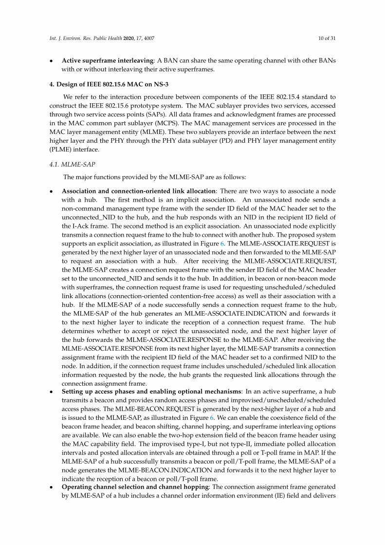
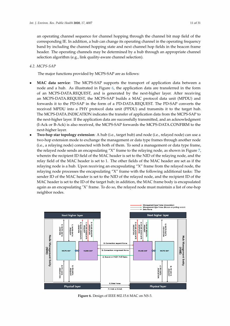
• Association and connection-oriented link allocation: There are two ways to associate a nodewith a hub. The first method is an implicit association. An unassociated node sends anon-command management type frame with the sender ID field of the MAC header set to theunconnected_NID to the hub, and the hub responds with an NID in the recipient ID field ofthe I-Ack frame. The second method is an explicit association. An unassociated node explicitlytransmits a connection request frame to the hub to connect with another hub. The proposed systemsupports an explicit association, as illustrated in Figure 6. The MLME-ASSOCIATE.REQUEST isgenerated by the next higher layer of an unassociated node and then forwarded to the MLME-SAPto request an association with a hub. After receiving the MLME-ASSOCIATE.REQUEST,the MLME-SAP creates a connection request frame with the sender ID field of the MAC headerset to the unconnected_NID and sends it to the hub. In addition, in beacon or non-beacon modewith superframes, the connection request frame is used for requesting unscheduled/scheduledlink allocations (connection-oriented contention-free access) as well as their association with ahub. If the MLME-SAP of a node successfully sends a connection request frame to the hub,the MLME-SAP of the hub generates an MLME-ASSOCIATE.INDICATION and forwards itto the next higher layer to indicate the reception of a connection request frame. The hubdetermines whether to accept or reject the unassociated node, and the next higher layer ofthe hub forwards the MLME-ASSOCIATE.RESPONSE to the MLME-SAP. After receiving theMLME-ASSOCIATE.RESPONSE from its next higher layer, the MLME-SAP transmits a connectionassignment frame with the recipient ID field of the MAC header set to a confirmed NID to thenode. In addition, if the connection request frame includes unscheduled/scheduled link allocationinformation requested by the node, the hub grants the requested link allocations through theconnection assignment frame.
• Setting up access phases and enabling optional mechanisms: In an active superframe, a hubtransmits a beacon and provides random access phases and improvised/unscheduled/scheduledaccess phases. The MLME-BEACON.REQUEST is generated by the next-higher layer of a hub andis issued to the MLME-SAP, as illustrated in Figure 6. We can enable the coexistence field of thebeacon frame header, and beacon shifting, channel hopping, and superframe interleaving optionsare available. We can also enable the two-hop extension field of the beacon frame header usingthe MAC capability field. The improvised type-I, but not type-II, immediate polled allocationintervals and posted allocation intervals are obtained through a poll or T-poll frame in MAP. If theMLME-SAP of a hub successfully transmits a beacon or poll/T-poll frame, the MLME-SAP of anode generates the MLME-BEACON.INDICATION and forwards it to the next higher layer toindicate the reception of a beacon or poll/T-poll frame.
• Operating channel selection and channel hopping: The connection assignment frame generatedby MLME-SAP of a hub includes a channel order information environment (IE) field and delivers
Int. J. Environ. Res. Public Health 2020, 17, 4007 11 of 31
an operating channel sequence for channel hopping through the channel bit map field of thecorresponding IE. In addition, a hub can change its operating channel in the operating frequencyband by including the channel hopping state and next channel hop fields in the beacon frameheader. The operating channels may be determined by a hub through an appropriate channelselection algorithm (e.g., link quality-aware channel selection).
4.2. MCPS-SAP
The major functions provided by MCPS-SAP are as follows:
• MAC data service: The MCPS-SAP supports the transport of application data between anode and a hub. As illustrated in Figure 6, the application data are transferred in the formof an MCPS-DATA.REQUEST, and is generated by the next-higher layer. After receivingan MCPS-DATA.REQUEST, the MCPS-SAP builds a MAC protocol data unit (MPDU) andforwards it to the PD-SAP in the form of a PD-DATA.REQUEST. The PD-SAP converts thereceived MPDU into a PHY protocol data unit (PPDU) and transmits it to the target hub.The MCPS-DATA.INDICATION indicates the transfer of application data from the MCPS-SAP tothe next-higher layer. If the application data are successfully transmitted, and an acknowledgment(I-Ack or B-Ack) is also received, the MCPS-SAP forwards the MCPS-DATA.CONFIRM to thenext-higher layer.
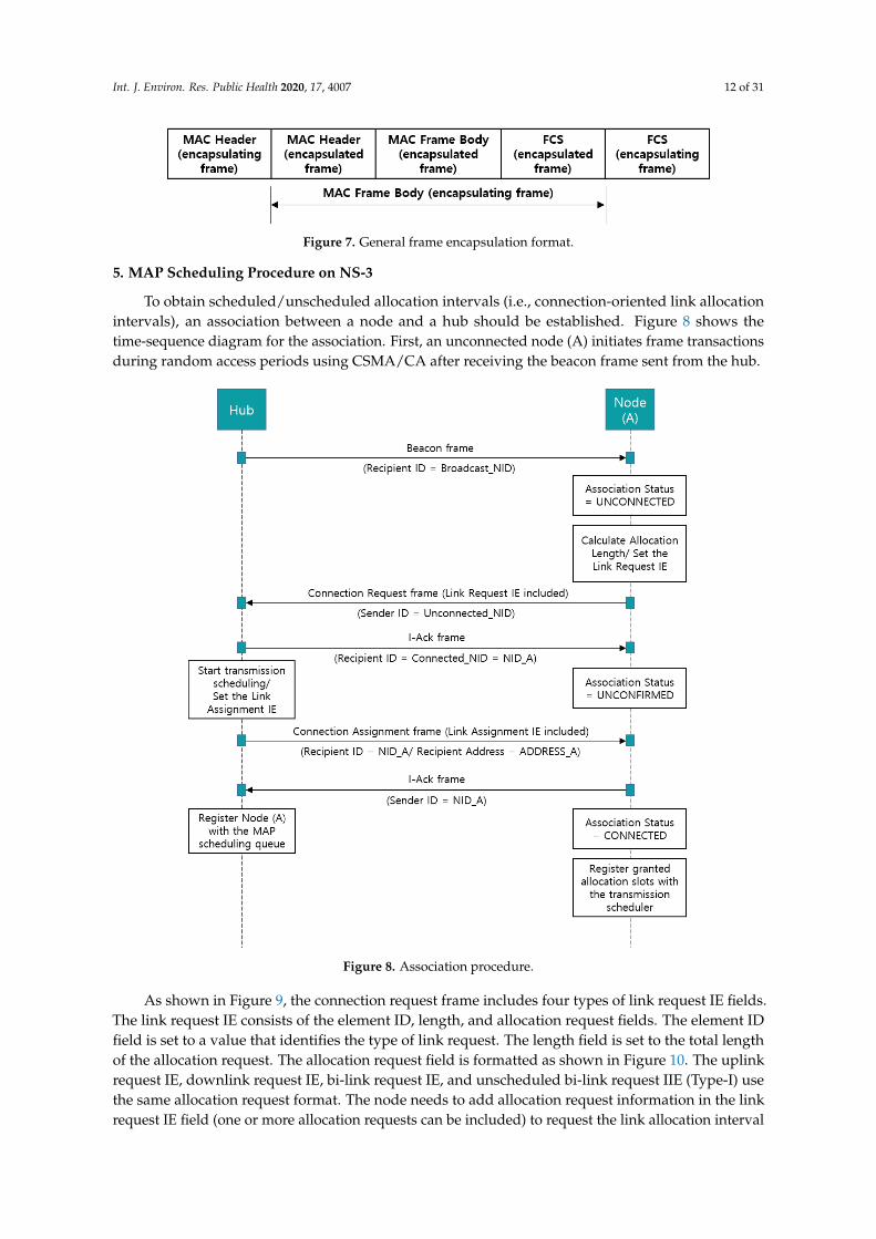
• Two-hop star topology extension: A hub (i.e., target hub) and node (i.e., relayed node) can use atwo-hop extension mode to exchange the management or data type frames through another node(i.e., a relaying node) connected with both of them. To send a management or data type frame,the relayed node sends an encapsulating “X” frame to the relaying node, as shown in Figure 7,wherein the recipient ID field of the MAC header is set to the NID of the relaying node, and therelay field of the MAC header is set to 1. The other fields of the MAC header are set as if therelaying node is a hub. Upon receiving an encapsulating “X” frame from the relayed node, therelaying node processes the encapsulating “X” frame with the following additional tasks: Thesender ID of the MAC header is set to the NID of the relayed node, and the recipient ID of theMAC header is set to the ID of the target hub; in addition, the MAC frame body is encapsulatedagain as an encapsulating "X" frame. To do so, the relayed node must maintain a list of one-hopneighbor nodes.
Figure 6. Design of IEEE 802.15.6 MAC on NS-3.
Int. J. Environ. Res. Public Health 2020, 17, 4007 12 of 31
Figure 7. General frame encapsulation format.
5. MAP Scheduling Procedure on NS-3
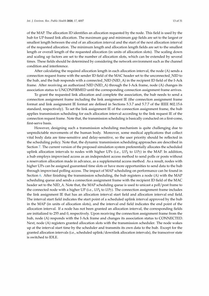
To obtain scheduled/unscheduled allocation intervals (i.e., connection-oriented link allocationintervals), an association between a node and a hub should be established. Figure 8 shows thetime-sequence diagram for the association. First, an unconnected node (A) initiates frame transactionsduring random access periods using CSMA/CA after receiving the beacon frame sent from the hub.
Figure 8. Association procedure.
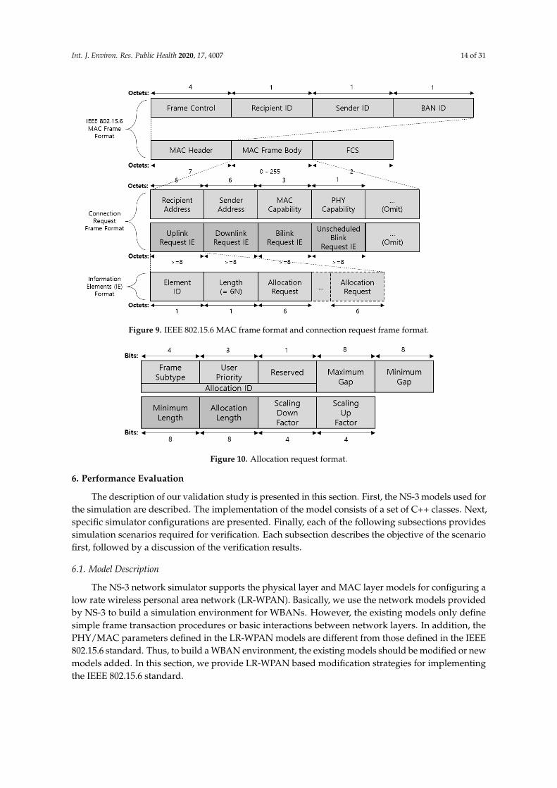
As shown in Figure 9, the connection request frame includes four types of link request IE fields.The link request IE consists of the element ID, length, and allocation request fields. The element IDfield is set to a value that identifies the type of link request. The length field is set to the total lengthof the allocation request. The allocation request field is formatted as shown in Figure 10. The uplinkrequest IE, downlink request IE, bi-link request IE, and unscheduled bi-link request IIE (Type-I) usethe same allocation request format. The node needs to add allocation request information in the linkrequest IE field (one or more allocation requests can be included) to request the link allocation interval
Int. J. Environ. Res. Public Health 2020, 17, 4007 13 of 31
of the MAP. The allocation ID identifies an allocation requested by the node. This field is used by thehub for UP-based link allocation. The maximum gap and minimum gap fields are set to the largest orsmallest length between the end of an allocation interval and the start of the next allocation intervalof the requested allocation. The minimum length and allocation length fields are set to the smallestlength or overall length of the requested allocation (in units of allocation slots). The scaling downand scaling up factors are set to the number of allocation slots, which can be extended by severaltimes. These fields should be determined by considering the network environment such as the channelcondition and interference.
After calculating the required allocation length in each allocation interval, the node (A) sends aconnection request frame with the sender ID field of the MAC header set to the unconnected_NID tothe hub, and the hub responds with a connected_NID (NID_A) in the recipient ID field of the I-Ackframe. After receiving an authorized NID (NID_A) through the I-Ack frame, node (A) changes itsassociation status to UNCONFIRMED until the corresponding connection assignment frame arrives.
To grant the requested link allocation and complete the association, the hub needs to send aconnection assignment frame including the link assignment IE (the connection assignment frameformat and link assignment IE format are defined in Sections 5.3.7 and 5.7.7 of the IEEE 802.15.6standard, respectively). To set the link assignment IE of the connection assignment frame, the hubapplies transmission scheduling for each allocation interval according to the link request IE of theconnection request frame. Note that, the transmission scheduling is basically conducted on a first-come,first-serve basis.
However, designing such a transmission scheduling mechanism is quite challenging due tounpredictable movements of the human body. Moreover, some medical applications that collectvital body data are time-sensitive and delay-sensitive, so the user priority should be reflected inthe scheduling policy. Note that, the dynamic transmission scheduling approaches are described inSection 7. The current version of the proposed simulation system preferentially allocates the scheduleduplink allocation intervals to nodes with higher UPs (i.e., UP4 to UP7) in the MAP. In addition,a hub employs improvised access as an independent access method to send polls or posts withouta reservation allocation made in advance, as a supplemental access method. As a result, nodes withhigher UPs can be assigned guaranteed time slots or have more opportunities to send data to the hubthrough improvised polling access. The impact of MAP scheduling on performance can be found inSection 6. After finishing the transmission scheduling, the hub registers a node (A) with the MAPscheduling queue and sends a connection assignment frame with the recipient ID field of the MACheader set to the NID_A. Note that, the MAP scheduling queue is used to unicast a poll/post frame tothe connected node with a higher UP (i.e., UP4 to UP7). The connection assignment frame includesthe link assignment IE that has an allocation interval start field and allocation interval end field.The interval start field indicates the start point of a scheduled uplink interval approved by the hubin the MAP (in units of allocation slots), and the interval end field indicates the end point of theallocation interval. If a node has not been granted an allocation interval, the corresponding fieldsare initialized to 255 and 0, respectively. Upon receiving the connection assignment frame from thehub, node (A) responds with the I-Ack frame and changes its association status to CONNECTED.Next, node (A) registers granted allocation slots with the transmission scheduler. The node wakesup at the interval start time by the scheduler and transmits its own data to the hub. Except for thegranted allocation intervals (i.e., scheduled uplink/downlink allocation intervals), the transceiver stateis switched to IDLE.
Int. J. Environ. Res. Public Health 2020, 17, 4007 14 of 31
Figure 9. IEEE 802.15.6 MAC frame format and connection request frame format.
Figure 10. Allocation request format.
6. Performance Evaluation
The description of our validation study is presented in this section. First, the NS-3 models used forthe simulation are described. The implementation of the model consists of a set of C++ classes. Next,specific simulator configurations are presented. Finally, each of the following subsections providessimulation scenarios required for verification. Each subsection describes the objective of the scenariofirst, followed by a discussion of the verification results.
6.1. Model Description
The NS-3 network simulator supports the physical layer and MAC layer models for configuring alow rate wireless personal area network (LR-WPAN). Basically, we use the network models providedby NS-3 to build a simulation environment for WBANs. However, the existing models only definesimple frame transaction procedures or basic interactions between network layers. In addition, thePHY/MAC parameters defined in the LR-WPAN models are different from those defined in the IEEE802.15.6 standard. Thus, to build a WBAN environment, the existing models should be modified or newmodels added. In this section, we provide LR-WPAN based modification strategies for implementingthe IEEE 802.15.6 standard.

Int. J. Environ. Res. Public Health 2020, 17, 4007 15 of 31
6.1.1. Physical Layer
The IEEE 802.15.6 standard supports three operational PHYs: narrowband (NB), ultra-wideband(UWB), and human body communications (HBC). The hub employs a slotted ALOHA or CSMA/CAprotocol depending on the selected PHY. In general, the CSMA/CA protocol is employed in NB PHY,and thus we use NB PHY in the simulation to implement a user-priority based CSMA/CA.
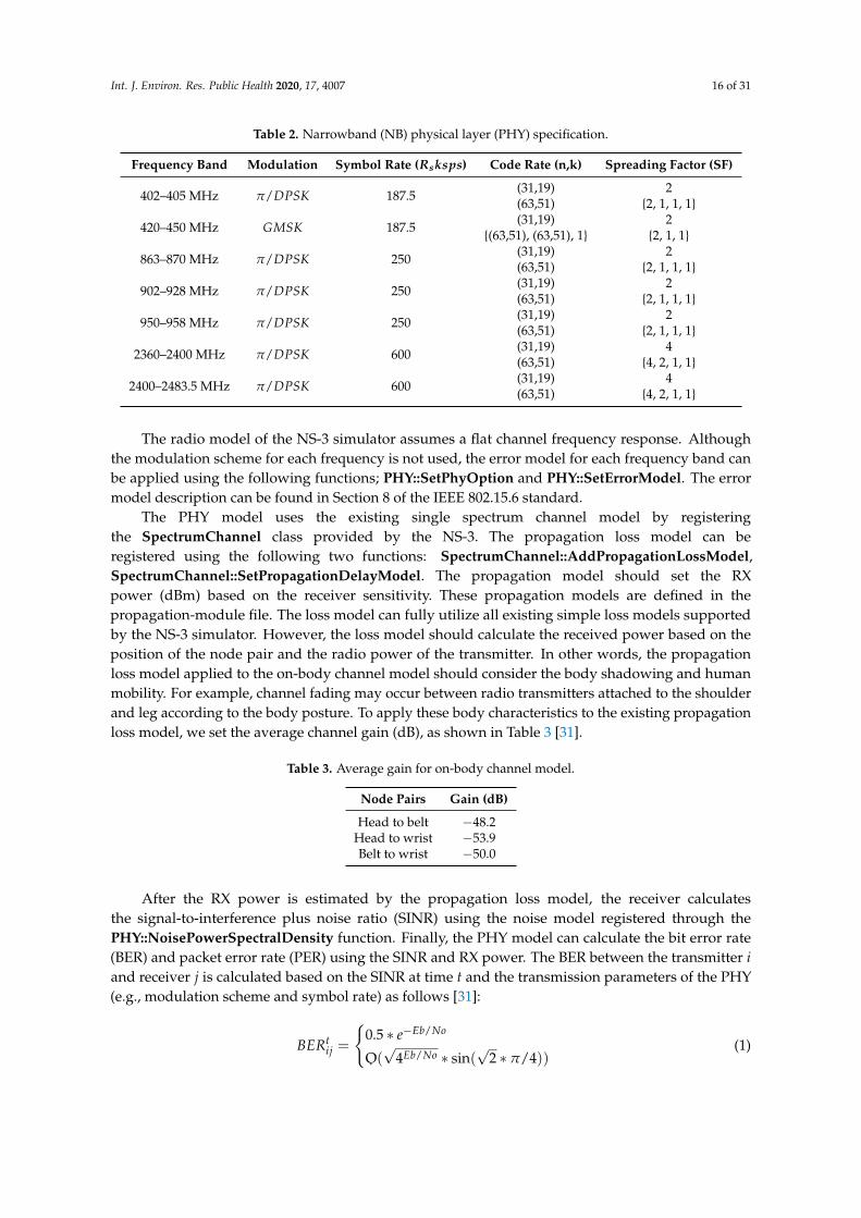
Table 2 summarizes the supported frequency bands and transmission parameters of the NBPHY [30]. However, because these parameters are requirements for transmitting radio signals inan actual WBAN environment, it is not necessary to implement the specifications in the simulation.The major functions of the IEEE 802.15.6 PHYs supported by an NS-3 simulator are a clear channelassessment (CCA), activation/deactivation of the radio transceiver, and transmission/reception ofthe physical layer protocol data unit (PPDU). The physical layer of the NS-3 consists of a PHY model,an error rate model, and a loss model. We model the PHY service specifications, PPDU formats,PHY constants, and protocol information base (PIB) attributes described in the IEEE 802.15.6 standard.The PIB to be managed in the PHY model are as follows: radio frequency channels, available channelssupported by a channel page, transmit power, current channel page, maximum number of symbolsin a frame, duration of the synchronization header in the symbols, and number of symbols per octet.The following functions are some of the important lists that the PHY model should implement.
• PHY::SetTxPowerSpectralDensity: Set the power spectral density of the outgoing signals.• PHY::SetNoisePowerSpectralDensity: Set the noise power spectral density. The noise power
density assumes a uniformly distributed thermal noise across the frequency bands.• PHY::SetChannel: Registers a wireless channel model to be used in the PHY model.• PHY::ChannelSupported: Check if the given channel is supported by the PHY model.• PHY::PhyIsBusy: Check if the PHY is busy, which is the case if the PHY is currently sending or
receiving a frame.• PHY::PdDataRequest: Send a data frame to the wireless channel.• PHY::PlmeDataRequest: Send a management frame to the wireless channel.• PHY::SetPdDataIndicationCallback: Set the callback for the end of an RX, as a part of the
interconnections between the PD-SAP and MCPS-SAP.• PHY::SetPlmeDataIndicationCallback: Set the callback for the end of an RX, as a part of the
interconnections between the PLME-SAP and MLME-SAP.• PHY::SetPlmeSetTRXStateConfirmCallback: Set the callback for the end of an SetTRXState,
as part of the interconnections between the PLME-SAP and MLME-SAP.• PHY::SetPlmeGetAttributeConfirmCallback: Set the callback for the end of an GetAttribute,
as part of the interconnections between the PLME-SAP and MLME-SAP.• PHY::SetPlmeCcaConfirmCallback: Set the callback for the end of a CCA, as a part of the
interconnections between the PHY and MAC. The CCA reports a busy medium upon detectingany energy above the receiver energy detection (ED) threshold.
• PHY::SetPlmeEdConfirmCallback: Set the callback for the end of an ED, as part of theinterconnections between the PHY and MAC. The ED estimates the received signal power withinthe bandwidth of the channel. This callback is intended for use by upper layers for various tasks,including part of a channel hopping algorithm.
Int. J. Environ. Res. Public Health 2020, 17, 4007 16 of 31
Table 2. Narrowband (NB) physical layer (PHY) specification.
Frequency Band Modulation Symbol Rate (Rsksps) Code Rate (n,k) Spreading Factor (SF)
402–405 MHz π/DPSK 187.5(31,19)(63,51)
2{2, 1, 1, 1}
420–450 MHz GMSK 187.5(31,19)
{(63,51), (63,51), 1}2
{2, 1, 1}
863–870 MHz π/DPSK 250(31,19)(63,51)
2{2, 1, 1, 1}
902–928 MHz π/DPSK 250(31,19)(63,51)
2{2, 1, 1, 1}
950–958 MHz π/DPSK 250(31,19)(63,51)
2{2, 1, 1, 1}
2360–2400 MHz π/DPSK 600(31,19)(63,51)
4{4, 2, 1, 1}
2400–2483.5 MHz π/DPSK 600(31,19)(63,51)
4{4, 2, 1, 1}
The radio model of the NS-3 simulator assumes a flat channel frequency response. Althoughthe modulation scheme for each frequency is not used, the error model for each frequency band canbe applied using the following functions; PHY::SetPhyOption and PHY::SetErrorModel. The errormodel description can be found in Section 8 of the IEEE 802.15.6 standard.
The PHY model uses the existing single spectrum channel model by registeringthe SpectrumChannel class provided by the NS-3. The propagation loss model can beregistered using the following two functions: SpectrumChannel::AddPropagationLossModel,SpectrumChannel::SetPropagationDelayModel. The propagation model should set the RXpower (dBm) based on the receiver sensitivity. These propagation models are defined in thepropagation-module file. The loss model can fully utilize all existing simple loss models supportedby the NS-3 simulator. However, the loss model should calculate the received power based on theposition of the node pair and the radio power of the transmitter. In other words, the propagationloss model applied to the on-body channel model should consider the body shadowing and humanmobility. For example, channel fading may occur between radio transmitters attached to the shoulderand leg according to the body posture. To apply these body characteristics to the existing propagationloss model, we set the average channel gain (dB), as shown in Table 3 [31].
Table 3. Average gain for on-body channel model.
Node Pairs Gain (dB)
Head to belt −48.2Head to wrist −53.9Belt to wrist −50.0
After the RX power is estimated by the propagation loss model, the receiver calculatesthe signal-to-interference plus noise ratio (SINR) using the noise model registered through thePHY::NoisePowerSpectralDensity function. Finally, the PHY model can calculate the bit error rate(BER) and packet error rate (PER) using the SINR and RX power. The BER between the transmitter iand receiver j is calculated based on the SINR at time t and the transmission parameters of the PHY(e.g., modulation scheme and symbol rate) as follows [31]:
BERtij =
{0.5 ∗ e−Eb/No
O(√
4Eb/No ∗ sin(√
2 ∗ π/4))(1)

Int. J. Environ. Res. Public Health 2020, 17, 4007 17 of 31
where Eb/No is the energy per bit-to-noise power spectral density ratio in dBm, which is calculatedas follows [31]:
Eb/No[dB] = SINRtij[dB] + 10 ∗ log10(BW/R) (2)
where BW denotes the bandwidth and R denotes the symbol rate. Finally, the PER is calculated usingthe following [31]:
PERij = 1− (1− BERtij)
n (3)
where n denotes the frame length in bits.
6.1.2. MAC Layer
The MAC model is conceptually divided into MCPS-SAP and MLME-SAP, whereas the relatedfunctions are defined in the same space, i.e., the WbanMac class. The WbanMac class provides theIEEE 802.15.6 MAC functions, and manages various MAC state variables such as an association,two-hop extension, ACK mode, and channel hopping. The WbanMac class refers to separate classesfor random access and time slotted access. The random access algorithm refers to the LrWpanCsmaCaclass provided by an NS-3 simulator, and we change the CW values according to the user priorities,as shown in Table 4. Each node uniformly selects a random value from the interval (1, CW) as aback-off counter.
Table 4. Bounds for CSMA/CA.
User Priority CWmin CWmax
0 16 641 16 322 8 323 8 164 4 165 4 86 2 87 1 4
The following functions are some of the important lists that the MAC model should implement.Note that, to use the functions provided by the PHY and MAC classes, a separate helper class mustbe implemented. We implemented a helper class (WbanHelper) that provides interface functionssuch as an association, spectrum channel registration, mobility model registration, and networkdevice management.
• MAC::McpsDataRequest: Request to transfer a MSDU.• MAC::SetMcpsDataIndicationCallback: Set the callback for the indication of an incoming data
frame. This callback implements MCPS-DATA.indication.• MAC::SetMcpsDataConfirmCallback: Set the callback for confirmation of a data frame
transmission request. This callback implements MCPS-DATA.confirm.• MAC::PdDataIndication: Indicate the transfer of an MPDU from PHY to MAC.• MAC::PdDataConfirm: Confirm the end of the transmission of an MPDU to MAC.• MAC::PlmeSetTRXState: Set the PHY state (RX_ON, TRX_OFF, FORCE_TRX_OFF, TX_ON).• MAC::SetWbanMacState: A random access algorithm (e.g., CSMA/CA) calls back the MAC after
executing a channel assessment. MacState indicates a BUSY or IDLE channel condition.• MAC::SetAccessModeStatus: Set the current access mode.• MAC::SetAssociationStatus: Set the current association status.• MAC::SetTwoHopExtensionStatus: Set the current topology extension status.• MAC::SetChannelHoppingStatus: Set the current channel hopping status.• MAC::SendAck: Send an acknowledgment packet (I-Ack or B-Ack) for the given
sequence number.
Int. J. Environ. Res. Public Health 2020, 17, 4007 18 of 31
6.1.3. Energy Model
Most network simulators focus on modeling the wireless energy consumption because theyassume that wireless communication consumes the most amount of power. The radio energyconsumption model allows users to set the specific power consumption of the radio for differentoperating states. However, an NS-3 simulator does not provide any radio energy consumption model.To track the power consumption of the physical layer, we provide an energy consumption model.The WbanEnergyModel class estimates the energy consumption based on transceiver states such asTX, RX, and IDLE in the physical layer. The amount of power consumed in each state is shown inTable 5. The proposed energy model detects the changes in the state of the transceiver through thefunction that switches the state of the transceiver (i.e., MAC::PlmeSetTRXState). The node waits inthe IDLE state until it acquires a channel in the random access interval. In the MAP, the transceiver isswitched to the TX state according to the transmission time granted by the hub. Similarly, the nodeswitches the transceiver to the RX state in the downlink interval approved by the hub. In other cases,the node goes to the SLEEP state.
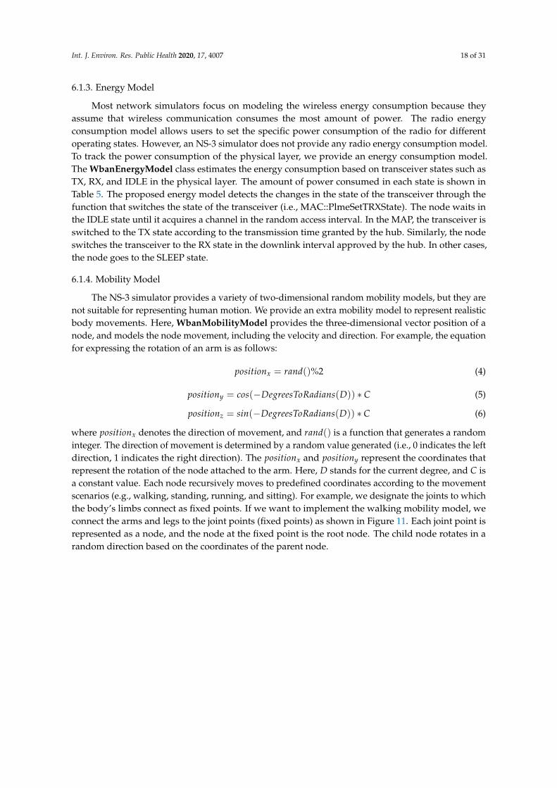
6.1.4. Mobility Model
The NS-3 simulator provides a variety of two-dimensional random mobility models, but they arenot suitable for representing human motion. We provide an extra mobility model to represent realisticbody movements. Here, WbanMobilityModel provides the three-dimensional vector position of anode, and models the node movement, including the velocity and direction. For example, the equationfor expressing the rotation of an arm is as follows:
positionx = rand()%2 (4)
positiony = cos(−DegreesToRadians(D)) ∗ C (5)
positionz = sin(−DegreesToRadians(D)) ∗ C (6)
where positionx denotes the direction of movement, and rand() is a function that generates a randominteger. The direction of movement is determined by a random value generated (i.e., 0 indicates the leftdirection, 1 indicates the right direction). The positionx and positiony represent the coordinates thatrepresent the rotation of the node attached to the arm. Here, D stands for the current degree, and C isa constant value. Each node recursively moves to predefined coordinates according to the movementscenarios (e.g., walking, standing, running, and sitting). For example, we designate the joints to whichthe body’s limbs connect as fixed points. If we want to implement the walking mobility model, weconnect the arms and legs to the joint points (fixed points) as shown in Figure 11. Each joint point isrepresented as a node, and the node at the fixed point is the root node. The child node rotates in arandom direction based on the coordinates of the parent node.

Int. J. Environ. Res. Public Health 2020, 17, 4007 19 of 31
Figure 11. An example of the walking model.
6.2. Simulation Setup
The goals of the experimental studies are as follows; (i) we verify that the proposed simulationsystem meets the requirements for performance described in the IEEE 802.15.6 standard; and (ii) weverify that the proposed simulation system can support recent WBAN research topics regarding thedynamic resource allocation, inter-WBAN interference mitigation, and intra-WBAN routing. To achievethis goal, we build a simulation environment closest to the real WBAN environment and then constructspecific simulation scenarios similar to the real health monitoring system. We evaluate the performanceof the proposed system using NS-3 version 3.29. The simulation settings are divided into two categories,i.e., the network model and simulation configuration.
The network models used for the simulation are shown in Table 5. The supported frequencybands and transmission parameters follow NB PHY. The radio model in the NS-3 simulator assumes aflat channel frequency response. The modulation scheme for each frequency is not applied, but theerror rate model is used based on the differential phase shift keying (DPSK) modulation with thehighest data rate (971.4 kbps). The CSMA/CA is adopted as a random-access mechanism. The userpriority for CSMA/CA is divided into eight levels, as shown in Table 4. I-Ack is adopted as an ACKpolicy. Among the three access modes, the beacon access mode with superframes, which includesthree types of access phases (among EAP1, EAP2, RAP1, RAP2, MAP1, and MAP2), is adopted as anaccess mode. The simulation parameters are shown in Table 5. The maximum number of BANs isset to five, and each BAN consists of one hub and eight heterogeneous sensor nodes. The numberof BANs is adjusted according to the simulation scenario. The length of an allocation slot is equalto pAllocationSlotMin + AllocationSlotLength(L) ∗ pAllocationSlotResolution, and the centralizedguard time is set to pSIFS + pExtraIFS + mClockResolution.

Int. J. Environ. Res. Public Health 2020, 17, 4007 20 of 31
Table 5. Simulation settings.
Network Model Value
PHY Narrowband PHYFrequency band/Number of channels 2400–2483.5 MHz/16Modulation/Symbol rate/Data rate DPSK/600 Ksps/971.4 kbps
Noise Additive white Gaussian noise (AWGN)Propagation loss Body shadowing and position-based
MAC IEEE 802.15.6 (Beacon with superframes)MAC options Two-hop star topology extension/channel hopping/I-Ack policy
Mobility Human mobility (walking, stand, sitting, etc.)
Simulation Parameter Value
Number of BANs 1 to 5Number of hubs 1Number of nodes 8Node (traffic) type Normal (UP = 0, 1, 2 ,3), emergency (UP = 4, 5), critical (UP = 6, 7)
TXpower/RXsensitivity −15 dBm/−83 dBmRXenergy/Idleenergy/Sleepenergy 19 mA/0.4 mA/0.03 mA
Payload size 0 to 256 bytespAllocationSlotMin 500 us
pAllocationSlotResolution 500 usAllocationSlotLength 1
Beacon length 240 mspSIFS/pMIFS/pExtraIFS 75 us/20 us/10 us
mClockResolution 4 usmTimeout 30 us
6.3. Performance Metrics
To verify the performance of the proposed system, we use three principal performance metrics,i.e., throughput, average delay, and power consumption. We define the throughput as the amount ofpayload transmitted successfully within a given time period. The detailed equations for calculatingother performance metrics are described in the following subsections.
6.3.1. Average Delay
After sending a management type frame or data frame with an I-Ack policy to a node, and if ahub is expecting no more frames waiting for transmission or retransmission in the current allocationinterval, the average delay (D) is defined as follows:
D = Tcu + Tpro + Tf rame (7)
where Tcu denotes the cumulative delay caused by the back-off time for a successfully transmittedframe, or the frame retransmission time, which includes the interframe space time (i.e., a node shouldwait a certain duration between the pSIFS and pExtraIFS before the retransmission of that frame).In addition, Tpro denotes the propagation delay, and Tf rame denotes the total duration of a frame, whichcomprises the symbols for the PLCP preamble, PLCP header, and PSDU, and is calculated by [1]as follows:
Tf rame = Ts ∗ (Npreamble + Nheader ∗ Sheader +Ntotal
log2(M)∗ SPSDU) (8)
where Ts, Sheader, SPSDU , and M are defined in the IEEE 802.15.6 standard, i.e., Tables 29 through 35,and Npreamble, Nheader, and Ntotal are defined in Sections 8.2, 8.3, and 8.4.4 in the IEEE 802.15.6 standard,respectively. In addition, Sheader and SPSDU refer to the spreading factor of the PLCP header and PSDU,and M denotes the cardinality of the constellation of a given modulation scheme.

Int. J. Environ. Res. Public Health 2020, 17, 4007 21 of 31
6.3.2. Power Consumption
The average power consumption (E) for a node is calculated as [22] follows:
E = (α− 1)Tcu ∗ Idleenergy + (α)L ∗ TXenergy + (α ∗ D)RXenergy + Sleepenergy (9)
where α denotes the average number of back-off stages or frame retransmissions, and L denotes thelength of the payload. In addition, Idleenergy, TXenergy, RXenergy, and Sleepenergy denote the energyconsumption in an idle state, RX state, RX state, and sleep state, respectively.
6.4. Verification Scenario 1: Heterogeneous Traffic Flow
According to the IEEE 802.15.6 standard, each BAN contains one hub and a range of nodesbetween 1 and 64. Each node collects different physical or chemical body data and transmits themto the hub based on the priorities of the body data. To send high-priority traffic, IEEE 802.15.6MAC provides a priority-based random-access phase and managed access phase in the superframe.We analyze the performance of the proposed system under a scenario in which one hub transmitsa beacon frame during each beacon period (superframe), except in inactive superframes. The nodeswitches its state to inactive (IDLE) in EAP 1, RAP 1, EAP 2, or RAP 2, if it does not need to transmit aframe in the corresponding access phase. The EAP is used only to send emergency and critical traffic,and the RAP is used to send all types of traffic. MAP arranges the scheduled uplink, downlink, andbi-link allocation intervals, as well as unscheduled bi-link allocation intervals. Improvised pollingallocation intervals are also optionally included in MAP to provide additional access periods withoutadvanced notice. In this experiment, we aim to show the differences in performance according to threetest cases to analyze the effects of MAP on the performance, such as the throughput and delay. Table 6shows the beacon parameters used for each test case.
Table 6. Beacon parameters.
Case 1: Allocation Interval Value (in Units of Allocation Slots)
EAP 1 60RAP 1 60EAP 2 60RAP 2 60
Case 2: Allocation Interval Value (in Units of Allocation Slots)
EAP 1 20RAP 1 20EAP 2 20RAP 2 20
Scheduled uplink interval (MAP 1,2) 80 (40 * 2)Scheduled downlink interval (MAP 1,2) 80 (40 * 2)
Case 3: Allocation Interval Value (in Units of Allocation Slots)
EAP 1 20RAP 1 20EAP 2 20RAP 2 20
Scheduled uplink interval (MAP 1,2) 20 (10 * 2)Improvised polled interval (MAP 1,2) 20 (10 * 2)
Unscheduled bi-link interval (MAP 1,2) 30 (15 * 2)Scheduled downlink interval (MAP 1,2) 20 (10 * 2)Improvised posted interval (MAP 1,2) 20 (10 * 2)Improvised polled interval (MAP 1,2) 20 (10 * 2)Scheduled bi-link interval (MAP 1,2) 30 (15 * 2)

Int. J. Environ. Res. Public Health 2020, 17, 4007 22 of 31
Under this scenario, the number of BANs is set to one, and a hub and node are interconnectedin a one-hop star topology. The MAC options (i.e., channel hopping and two-hop star topologyextension) are not enabled. The other simulation parameters are shown in Table 5. After the hubassigns a connected_NID to an unconnected node through the connection assignment frame, it shouldprovide scheduled allocation intervals and polled allocation intervals to the connected node in MAP.Note that the hub grants scheduled allocation intervals (Cases 2 and 3) and improvised Type-I polledallocation intervals (Case 3) only to emergency and critical nodes. As shown in Figure 12, the hubgrants a Type-I polled allocation to the node, which starts at pSIFS and ends at the end of the allocationinterval. By using this scenario, we verified that each node can achieve a differentiated QoS based onthe traffic priorities.
Figure 12. Frame transactions for improvised access in MAP.
Results and Discussion
In general, the throughput and delay vary considerably with different data rates (in this case,we set the data rate to 971.4 kbps) over the frequency bands. Except for the reason based on the PHYcharacteristics, there are two main reasons for the differences in the throughput and delay dependingon the type of traffic. First, each node uniformly selects a random value from the interval (CWmin,CWmax) as a back-off counter during the contention access period (i.e., EAP1, RAP1, EAP2, and RAP2).That is, traffic with a low user priority has less chance of acquiring a channel during the contentionaccess period. This is particularly true for BANs with large numbers of nodes. Second, a node with ahigh user priority (i.e., a node classified as an emergency or critical node) establishes an associationwith a hub and is assigned scheduled allocation intervals and improvised polling access intervals inMAP by the hub. That is, even if the emergency or critical node cannot acquire a channel during thecontention access period, channel acquisition is guaranteed during the current superframe period.
In case 1, only EAP 1, 2 and RAP 1, 2 exist in the superframe. Because nodes with higher UPs(i.e., UP4 to UP7) use EAP and RAP together, there are more opportunities to acquire channels thanfor nodes with lower UPs (i.e., UP0 to UP3). However, the difference in performance between eachnode is not great, as illustrated in Figure 13a,b. The reason is that all nodes acquire channels basedon the CSMA/CA mechanism, even if the differentiated back-off counter is set according to userpriority. The latency to acquire the channel increases as collision occurs, thereby reducing the overallthroughput. That is, the contention-based channel access mechanism cannot satisfy the requirementsof delay-sensitive medical applications because the allocation intervals are not guaranteed.
For case 2, MAP 1 and 2, including a scheduled uplink and downlink allocation interval, are addedto the superframe. The nodes with higher UPs have higher transmission opportunities than nodeswith lower UPs because the uplink allocation slots are preferentially allocated to the critical nodethrough an association with the hub. For this reason, there is a large difference in throughput anddelay between each node, as shown in Figure 13c,d. However, if the expected transmission timeof the data including the guard time is larger than the remaining time slot, then the node will giveup the current transmission. In addition, if the node no longer has data in the transmisssion queue,the remaining time slots can be wasted. Therefore, even if the scheduled allocation interval is long inthe MAP, the performance will not be improved significantly.
Int. J. Environ. Res. Public Health 2020, 17, 4007 23 of 31
0 50 100 150 200 2500
100
200
300
400
500
600
700
Th
roug
hput
(Kbp
s)
Payload (Bytes)
UP0 UP1 UP2 UP3 UP4 UP5 UP6 UP7
(a)
0 50 100 150 200 2500
2
4
6
8
10
12
14
16
18
20
Del
ay (m
s)
Payload (Bytes)
UP0 UP1 UP2 UP3 UP4 UP5 UP6 UP7
(b)
0 50 100 150 200 2500
100
200
300
400
500
600
700
Thro
ughp
ut (K
bps)
Payload (Bytes)
UP0 UP1 UP2 UP3 UP4 UP5 UP6 UP7
(c)
0 50 100 150 200 2500
2
4
6
8
10
12
14
16
18
20
Del
ay (m
s)
Payload (Bytes)
UP0 UP1 UP2 UP3 UP4 UP5 UP6 UP7
(d)
0 50 100 150 200 2500
100
200
300
400
500
600
700
Thro
ughp
ut (K
bps)
Payload (Bytes)
UP0 UP1 UP2 UP3 UP4 UP5 UP6 UP7
(e)
0 50 100 150 200 250
2
4
6
8
10
12
14
16
18
20
Del
ay (m
s)
Payload (Bytes)
UP0 UP1 UP2 UP3 UP4 UP5 UP6 UP7
(f)
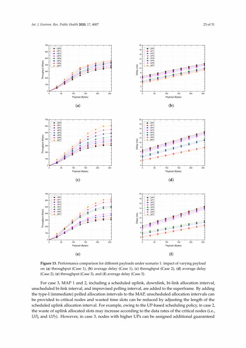
Figure 13. Performance comparison for different payloads under scenario 1: impact of varying payloadon (a) throughput (Case 1), (b) average delay (Case 1), (c) throughput (Case 2), (d) average delay(Case 2), (e) throughput (Case 3), and (f) average delay (Case 3).
For case 3, MAP 1 and 2, including a scheduled uplink, downlink, bi-link allocation interval,unscheduled bi-link interval, and improvised polling interval, are added to the superframe. By addingthe type-I (immediate) polled allocation intervals to the MAP, unscheduled allocation intervals canbe provided to critical nodes and wasted time slots can be reduced by adjusting the length of thescheduled uplink allocation interval. For example, owing to the UP-based scheduling policy, in case 2,the waste of uplink allocated slots may increase according to the data rates of the critical nodes (i.e.,UP6 and UP7). However, in case 3, nodes with higher UPs can be assigned additional guaranteed
Int. J. Environ. Res. Public Health 2020, 17, 4007 24 of 31
time slots through a poll frame transmitted by the hub at the polling access interval. As illustrated inFigure 13e,f, the performance of a node with a higher UP (i.e., UP4 to UP7) is higher than that of a nodewith a lower UP (i.e., UP0 to UP3). In addition, the difference in performance between the emergencynode (i.e., UP4 and UP5) and critical node (i.e., UP6 and UP7) is insignificant. The reason is that thewasted time slots can be reduced by adjusting the length of the scheduled uplink allocation interval,and additional allocation intervals are granted to the emergency node (i.e., UP4 and UP5) throughimprovised polling access.
6.5. Verification Scenario 2: Channel Sharing between Multi-WBANs
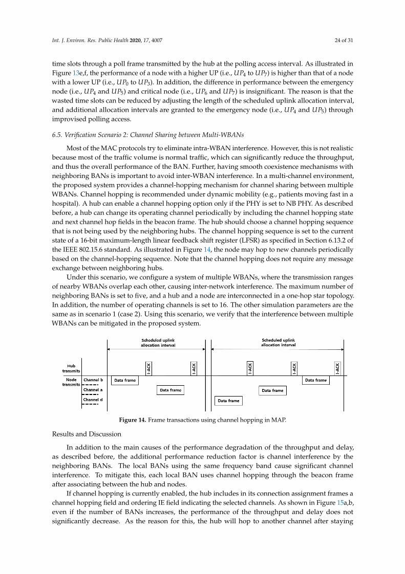
Most of the MAC protocols try to eliminate intra-WBAN interference. However, this is not realisticbecause most of the traffic volume is normal traffic, which can significantly reduce the throughput,and thus the overall performance of the BAN. Further, having smooth coexistence mechanisms withneighboring BANs is important to avoid inter-WBAN interference. In a multi-channel environment,the proposed system provides a channel-hopping mechanism for channel sharing between multipleWBANs. Channel hopping is recommended under dynamic mobility (e.g., patients moving fast in ahospital). A hub can enable a channel hopping option only if the PHY is set to NB PHY. As describedbefore, a hub can change its operating channel periodically by including the channel hopping stateand next channel hop fields in the beacon frame. The hub should choose a channel hopping sequencethat is not being used by the neighboring hubs. The channel hopping sequence is set to the currentstate of a 16-bit maximum-length linear feedback shift register (LFSR) as specified in Section 6.13.2 ofthe IEEE 802.15.6 standard. As illustrated in Figure 14, the node may hop to new channels periodicallybased on the channel-hopping sequence. Note that the channel hopping does not require any messageexchange between neighboring hubs.
Under this scenario, we configure a system of multiple WBANs, where the transmission rangesof nearby WBANs overlap each other, causing inter-network interference. The maximum number ofneighboring BANs is set to five, and a hub and a node are interconnected in a one-hop star topology.In addition, the number of operating channels is set to 16. The other simulation parameters are thesame as in scenario 1 (case 2). Using this scenario, we verify that the interference between multipleWBANs can be mitigated in the proposed system.
Figure 14. Frame transactions using channel hopping in MAP.
Results and Discussion
In addition to the main causes of the performance degradation of the throughput and delay,as described before, the additional performance reduction factor is channel interference by theneighboring BANs. The local BANs using the same frequency band cause significant channelinterference. To mitigate this, each local BAN uses channel hopping through the beacon frameafter associating between the hub and nodes.
If channel hopping is currently enabled, the hub includes in its connection assignment frames achannel hopping field and ordering IE field indicating the selected channels. As shown in Figure 15a,b,even if the number of BANs increases, the performance of the throughput and delay does notsignificantly decrease. As the reason for this, the hub will hop to another channel after staying

Int. J. Environ. Res. Public Health 2020, 17, 4007 25 of 31
in the current channel for numerous superframe periods as communicated to the associated nodes.The hub generates a channel-hopping sequence based on the current channel state and number ofcoexisting BANs. The current version of the proposed simulation system simply chooses a channelhopping sequence that is not being used by its neighbor BANs. However, if there are more neighboringBANs than the number of available channels, collisions will occur. In addition, the hub needs tocalculate a new channel hopping sequence and propagate the changed information to the node via theconnection assignment frame, thereby the control overhead also increases. To overcome the limitationof the channel hopping mechanism, the hub can optimize the channel hopping sequence by utilizinghistorical data on the channel usage of the neighboring BANs. One of the solutions to solve theproblem of the channel hopping mechanism is presented in Section 7. In conclusion, because thenumber of retransmissions from channel interference does not increase significantly, the QoS of trafficwith a higher user priority can be guaranteed. Moreover, the contention for channel acquisition isapplied independently for each BAN because the operating channels are no longer shared betweencoexisting BANs in the random access phase. As a result, normal traffic with a lower user priority canalso maintain its performance.
1 2 3 4 50
100
200
300
400
500
600
700
800
Thro
ughp
ut (K
bps)
Number of BANs (n)
UP0 UP4 UP7
(a)
1 2 3 4 50
5
10
15
20
25
Del
ay (m
s)
Number of BANs (n)
UP0 UP4 UP7
(b)
Figure 15. Performance comparison for different numbers of BANs in scenario 2: Impact of varyingnumbers of BANs on the (a) throughput and (b) average delay.
6.6. Verification Scenario 3: Two-Hop Star Topology Extension
In a one-hop star topology, frame exchanges between the hub and nodes occur directly. However,the nodes far from the hub (e.g., nodes attached to the arms and legs) should use a large amount oftransmission power, thereby compromising the lifetime of the network. However, in a two-hop startopology, a hub and node can exchange frames optionally through a relay-capable node. In addition,a two-hop star topology extension is a prerequisite supporting the routing protocol studied in a WBAN.To send a frame through the relaying node to the hub, as illustrated in Figure 7, the relayed node sendsan encapsulating “X” frame to the relaying node, wherein the recipient ID field of the MAC headeris set to the NID of the relaying node, and the relay field of the MAC header is set to 1. The framepayload is set to the encapsulated “X” frame. After receiving the encapsulating “X” frame from therelayed node, the relaying node forwards the frame to the hub in the same way as a one-hop startopology. To obtain scheduled allocation intervals for a two-hop extension, the relayed node shouldsend an encapsulated connection request frame through the relaying node to the hub, as specified inSection 6.10.5 of the IEEE 802.15.6 standard. After the association between the relayed node and hubis completed, the relaying node and relayed node use their scheduled allocation intervals, as shownin Figure 16.
Under this scenario, the number of BANs is set to one, and a hub and several nodes areinterconnected in a two-hop star topology. We set four normal nodes as relayed nodes and four
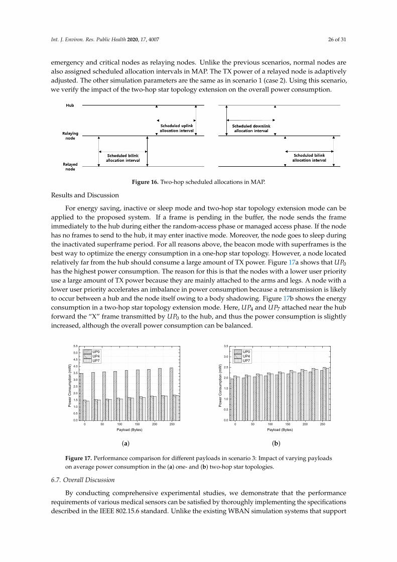
Int. J. Environ. Res. Public Health 2020, 17, 4007 26 of 31
emergency and critical nodes as relaying nodes. Unlike the previous scenarios, normal nodes arealso assigned scheduled allocation intervals in MAP. The TX power of a relayed node is adaptivelyadjusted. The other simulation parameters are the same as in scenario 1 (case 2). Using this scenario,we verify the impact of the two-hop star topology extension on the overall power consumption.
Figure 16. Two-hop scheduled allocations in MAP.
Results and Discussion
For energy saving, inactive or sleep mode and two-hop star topology extension mode can beapplied to the proposed system. If a frame is pending in the buffer, the node sends the frameimmediately to the hub during either the random-access phase or managed access phase. If the nodehas no frames to send to the hub, it may enter inactive mode. Moreover, the node goes to sleep duringthe inactivated superframe period. For all reasons above, the beacon mode with superframes is thebest way to optimize the energy consumption in a one-hop star topology. However, a node locatedrelatively far from the hub should consume a large amount of TX power. Figure 17a shows that UP0
has the highest power consumption. The reason for this is that the nodes with a lower user priorityuse a large amount of TX power because they are mainly attached to the arms and legs. A node with alower user priority accelerates an imbalance in power consumption because a retransmission is likelyto occur between a hub and the node itself owing to a body shadowing. Figure 17b shows the energyconsumption in a two-hop star topology extension mode. Here, UP4 and UP7 attached near the hubforward the “X” frame transmitted by UP0 to the hub, and thus the power consumption is slightlyincreased, although the overall power consumption can be balanced.
0 50 100 150 200 2500.0
0.5
1.0
1.5
2.0
2.5
3.0
3.5
4.0
4.5
5.0
5.5
Pow
er C
onsu
mpt
ion
(mW
)
Payload (Bytes)
UP0 UP4 UP7
(a)
0 50 100 150 200 2500.0
0.5
1.0
1.5
2.0
2.5
3.0
3.5
Pow
er C
onsu
mpt
ion
(mW
)
Payload (Bytes)
UP0 UP4 UP7
(b)
Figure 17. Performance comparison for different payloads in scenario 3: Impact of varying payloadson average power consumption in the (a) one- and (b) two-hop star topologies.
6.7. Overall Discussion
By conducting comprehensive experimental studies, we demonstrate that the performancerequirements of various medical sensors can be satisfied by thoroughly implementing the specificationsdescribed in the IEEE 802.15.6 standard. Unlike the existing WBAN simulation systems that support

Int. J. Environ. Res. Public Health 2020, 17, 4007 27 of 31
only contention-based random access, our simulation system supports heterogeneous traffic flow byimplementing the MAP specified in the IEEE 802.15.6 standard. The MAP is essential to implement aconnection-oriented link allocation mechanism between a hub and a node. From the experimentalresults, we can see that the transmission scheduling mechanism in MAP has a significant impact onthroughput and delay. Our simulation system provides two optional mechanisms specified in the IEEE802.15.6 standard, such as a channel hopping mechanism and two-hop topology extension, whichare essential for efficient resource management. By defining frame transaction procedures for theseadditional mechanisms, our simulation system can support inter-WBAN interference mitigation andintra-WBAN routing studies.
In conclusion, our simulation system can provide a practical simulation environment for buildinga health monitoring system, and support the latest WBAN research topics regarding the dynamicresource allocation/transmission scheduling, inter-WBAN interference mitigation, and intra-WBANrouting. The WBAN research domains in which the proposed simulation system can be used areintroduced in the next section.
7. Future Works and Challenges
The proposed system was developed based on the IEEE 802.15.6 standard. The IEEE 802.15.6standard has already been optimized for body area networks, but there are some factors that canimprove the performance or additional constraints that need to be reflected in the MAC design. Thefollowing sections describe the characteristics that should be considered in the IEEE 802.15.6 MACprotocol and present future studies that will be reflected in the proposed system.
7.1. Dynamic Transmission Scheduling
The WBAN topology may completely change because of changes in the posture and movementeven within a certain posture type. The WBAN also moves as a whole within an ambient network.Unpredictable movements of the human body and changes in posture can significantly degrade thenetwork performance such as the energy consumption, reliability, and delay. Particularly in terms ofthe energy consumption, ultra-low-power communication is required when considering the movementof the body because it is difficult to recharge the battery for each node inserted inside the human body.That is, the transmission policy should be adaptively changed according to the body posture and userpriority for efficient resource management [32–34]. Human posture is defined by four positions (i.e.,standing, sitting, lying, and walking), and a path loss model is developed according to a channel fadingthat occurs during each posture. We plan to study a transmission scheduling policy that maximizesthe performance (i.e., a high throughput, low bit-error rate, and low delay) for each state after definingthe state according to the body posture.
7.2. Dynamic Power Control
The specific absorption rate (SAR) is the rate at which the human body absorbs radio frequency(RF) radiation. In the United States, the Food and Drug Administration has the authority overhealth-related regulations for RF energy and issues regulations for acceptable limits of RF energy fromelectronic devices. Significant amounts of RF energy can increase the body temperature and causetissue damage, particularly to the eyes and testes, which are more vulnerable owing to their smallerblood flow than other parts of the body for dissipating heat. To reduce tissue heating, the transmissionpower of the radio can be limited. However, existing studies on dynamic transmission power controlhave not taken into account the bio-effects [35–37]. We plan to propose a transmission power controlmodel regarding the effect caused by biosensors to the human body in both near-field and far-fieldcommunication using the SAR. In addition, we will study an algorithm that calculates the optimalpower required for transmission when a channel fading is expected between the node and coordinatorwhen transmitting critical data.

Int. J. Environ. Res. Public Health 2020, 17, 4007 28 of 31
7.3. Priority-Aware Time Slotted Channel Hopping
In a multi-channel environment, the proposed system provides a channel-hopping mechanismfor channel sharing between multiple WBANs. The existing channel-hopping mechanism can avoidcollisions with adjacent BANs in frequency bands that provide high data rates or large numbersof channels. However, when numerous local BANs simultaneously use a low-frequency band,the existing resource-sharing mechanisms need to be changed. That is, the channel sharing policyshould guarantee the use of the channel for a critical data transmission [38,39]. In the future, we willstudy a priority-aware time-slotted channel-hopping algorithm between multiple WBANs to supportthe QoS of critical data.
7.4. Security Mechanism for Inter-WBAN and Beyond-WBAN Communications
To provide reliable security services for intra-WBAN communications, the IEEE 802.15.6standard specifies a security association between a hub and a node. For secure communicationwith authenticated nodes, the hub uses the AES-128 encryption algorithm. Unlike intra-WBAN,which has limited capacity and computing power, a higher level of security technology should beapplied for inter-WBAN communications or beyond-WBAN communications. In order to handlethe protected health information generated by medical applications, the authors [40] proposeutilizing blockchain-based smart contracts to facilitate secure analysis and management of medicalsensors. Similarly, the authors [41] propose a hierarchical trust networking architecture based ona permissioned blockchain. Also, the authors [42] employ a blockchain to construct heterogeneousmobile edge computing (MEC) systems. The combination of blockchain and distributed multi-domainnetworks can effectively accomplish the topology privacy protection of MEC systems. In thefuture, we will study blockchain-based secure communication protocols for inter-WBAN andbeyond-WBAN communications.
8. Conclusions
To build a realistic WBAN simulation system, we proposed the use of modeling strategies forimplementing the IEEE 802.15.6 MAC on an NS-3 simulator. Unlike the existing WBAN simulationsystems, we implemented additional mechanisms such as association, connection-oriented linkallocation, a channel-hopping mechanism for mitigating inter-WBAN interference, and a two-hopstar topology extension. In addition, we evaluated the performance of the proposed simulationsystem under realistic WBAN scenarios such as a heterogeneous traffic flow, channel sharing betweenmulti-WBANs, and a two-hop star network topology. The simulation results demonstrate that thecomplementary mechanisms and realistic WBAN scenarios make our simulation platform closer tothat of a practical WBAN system. Finally, we presented the unique characteristics of a WBAN that needto be considered in the IEEE 802.15.6 standard. Although the IEEE 802.15.6 standard has already beenoptimized for a practical WBAN system, there are additional factors degrading the overall performance.In a future study, we will present a modeling strategy to improve the link allocation and resourcemanagement scheme of the IEEE 802.15.6 standard.
Author Contributions: B.-S.K., T.-E.S. and K.-I.K. contributed to the modeling and implementation of the standard.They also conducted the performance analysis. All authors have read and agreed to the published version of themanuscript.
Funding: This research was supported by the Basic Science Research Program through the National ResearchFoundation of Korea (NRF) funded by the Ministry of Education (NRF-2019R1A6A3A13091006).
Conflicts of Interest: The authors declare no potential conflict of interest.

Int. J. Environ. Res. Public Health 2020, 17, 4007 29 of 31
References
1. 802.15.6-2012 IEEE Standards for Local and Metropolitan Area Networks–Part 15.6: Wireless Body Area Networks;IEEE: Piscataway, NJ, USA, 2012.
2. Wireless LAN medium access control (MAC) and physical layer (PHY) specifications. In ANSI/IEEE Std.802.11-1999; IEEE: Piscataway, NJ, USA, 1999.
3. Kim, B.S.; Kim, K.I.; Shah, B.; Ullah, S. A forwarder based temperature aware routing protocol in wirelessbody area networks. J. Internet Technol. 2019, 20, 1157–1166.
4. Sagar, A.K.; Singh, S.; Kumar, A. Energy-aware WBAN for health monitoring using critical data routing(CDR). Wirel. Pers. Commun. 2020, 112, 273–302. [CrossRef]
5. Ahmed, O.; Ren, F.; Hawbani, A.; Al-sharabi, Y. Energy optimized congestion control based temperatureaware routing algorithm for software defined wireless body area networks. IEEE Access 2020, 8, 41085–41099.[CrossRef]
6. Pandey, A.K.; Gupta, N. An energy efficient distributed queuing random access (EE-DQRA) MAC protocolfor wireless body sensor networks. Wirel. Netw. 2020, 26, 2875–2889. [CrossRef]
7. Zang, W.; Miao, F.; Gravina, R.; Sun, F.; Fortino, G.; Li, Y. CMDP-based intelligent transmission for wirelessbody area network in remote health monitoring. Neural Comput. Appl. 2020, 32, 829–837. [CrossRef]
8. Badreddine, W.; Chaudet, C.; Petruzzi, F.; Potop-Butucaru, M. Broadcast strategies and performanceevaluation of IEEE 802.15. 4 in wireless body area networks WBAN. Ad Hoc Netw. 2020, 97, 102006.[CrossRef]
9. Li, C.; Li, H.B.; Kohno, R. Performance evaluation of IEEE 802.15.4 for wireless body area network(WBAN). In Proceedings of the International Conference on Communications Workshops, Dresden, Germany,14–18 June 2009; IEEE: Piscataway, NJ, USA, 2009; pp. 1–5.
10. Borges, L.M.; Velez, F.J.; Lebres, A.S. Performance evaluation of the schedule channel polling MAC protocolapplied to health monitoring in the context of IEEE 802.15.4. In Proceedings of the 17th European Wireless2011-Sustainable Wireless Technologies, Vienna, Austria, 27–29 April 2011; VDE VERLAG GmbH: Berlin,Germany, 2011; pp. 1–8.
11. Deylami, M.; Jovanov, E. A distributed and collaborative scheme for mitigating coexistence in IEEE 802.15.4based WBANs. In Proceedings of the International Conference on Annual Southeast Regional Conference,Clemson, SC, USA, 7–8 April 2000; 2012; pp. 1–6.
12. Kim, Y.; Lee, S.; Lee, S. Coexistence of ZigBee-based WBAN and WiFi for health telemonitoring systems.J. Biomed. Health Inform. 2015, 20, 222–230. [CrossRef]
13. Ullah, S.; Chen, M.; Kwak, K.S. Throughput and delay analysis of IEEE 802.15.6-based CSMA/CA protocol.J. Med. Syst. 2012, 36, 3875–3891. [CrossRef]
14. Khan, J.Y.; Yuce, M.R.; Bulger, G.; Harding, B. Wireless body area network (WBAN) design techniques andperformance evaluation. J. Med. Syst. 2012, 36, 1441–1457. [CrossRef]
15. Kahsay, L.Z.; Paso, T.; Iinatti, J. Evaluation of IEEE 802.15.6 MAC user priorities with UWB PHY for medicalapplications. In Proceedings of the International Conference on Medical Information and CommunicationTechnology (ISMICT), Tokyo, Japan, 6–8 March 2013; IEEE: Piscataway, NJ, USA, 2013; pp. 18–22.
16. Fourati, H.; Idoudi, H.; Val, T.; Van Den Bossche, A.; Saidane, L.A. Performance evaluation of ieee 802.15.6csma/ca-based canet wban. In Proceedings of the International Conference on Computer Systems andApplications (ICCSA), Marrakech, Morocco, 17–20 November 2015; IEEE: Piscataway, NJ, USA, 2015; pp. 1–7.
17. Yue, W.; Li, C.; Song, Y.; Yang, L.; Yuan, X. WBAN on NS-3: Novel implementation with high performance ofIEEE 802.15.6. In Proceedings of the International Conference on Wireless Communications and Networking,Doha, Qatar, 3–6 April 2016; IEEE: Piscataway, NJ, USA, 2016; pp. 1–6.
18. Su, X.; Li, C.; Song, Y.; Yuan, X. WBAN on hardware: Implementation and optimization based on IEEE802.15.6. In Proceedings of the International Conference on Computer, Information and TelecommunicationSystems (CITS), Dalian, China, 21–23 July 2017; IEEE: Piscataway, NJ, USA, 2017; pp. 147–151.
19. Yuan, X.; Li, C.; Ye, Q.; Zhang, K.; Cheng, N.; Zhang, N.; Shen, X. Performance analysis of IEEE 802.15.6-basedcoexisting mobile WBANs with prioritized traffic and dynamic interference. IEEE Trans. Wirel. Commun.2018, 17, 5637–5652. [CrossRef]

Int. J. Environ. Res. Public Health 2020, 17, 4007 30 of 31
20. Viittala, H.; Hamalainen, M.; Iinatti, J.; Taparugssanagorn, A. Different experimental WBAN channel modelsand IEEE 802.15.6 models: Comparison and effects. In Proceedings of the International Conference onApplied Sciences in Biomedical and Communication Technologies, Bratislava, Slovakia, 24–27 November2009; IEEE: Piscataway, NJ, USA, 2009; pp. 1–5.
21. Naganawa, J.I.; Wangchuk, K.; Kim, M.; Aoyagi, T.; Takada, J.I. Simulation-based scenario-specific channelmodeling for wban cooperative transmission schemes. J. Biomed. Health Inform. 2014, 19, 559–570. [CrossRef][PubMed]
22. Sarkar, S.; Misra, S.; Bandyopadhyay, B.; Chakraborty, C.; Obaidat, M.S. Performance analysis of IEEE802.15.6 MAC protocol under non-ideal channel conditions and saturated traffic regime. IEEE Trans. Comput.2015, 64, 2912–2925. [CrossRef]
23. Hoeckel, A.; Lee, G.; Forrister, E.; Xue, D.; Benton, G.; Garner, B.; Li, Y. Simulation and measurementof dynamic on-body wave propagations. In Proceedings of the 2015 Texas Symposium on Wireless andMicrowave Circuits and Systems (WMCS), Waco, TX, USA, 23–24 April 2015; IEEE: Piscataway, NJ, USA,2015; pp. 1–4.
24. Kim, B.S.; Kim, K.H.; Shah, B.; Kim, K.I. Mobility and temperature aware QoS routing protocol inwireless body area networks. In Proceedings of the International Conference on Computational Science andComputational Intelligence (CSCI), Las Vegas, NV, USA, 14–16 December 2017; IEEE: Piscataway, NJ, USA,2017; pp. 1818–1819.
25. Ahmed, G.; Mahmood, D.; Islam, S. Thermal and energy aware routing in wireless body area networks.J. Distrib. Sens. Netw. 2019, 15, 1550147719854974. [CrossRef]
26. Kim, B.S.; Shah, B.; Al-Obediat, F.; Ullah, S.; Kim, K.H.; Kim, K.I. An enhanced mobility and temperatureaware routing protocol through multi-criteria decision making method in wireless body area networks.Appl. Sci. 2018, 8, 2245. [CrossRef]
27. Ullah, S.; Tovar, E.; Kim, K.I.; Kim, K.H.; Imran, M. Performance analysis of priority-based IEEE 802.15.6protocol in saturated traffic conditions. IEEE Access 2018, 6, 66198–66209. [CrossRef]
28. Ullah, S.; Kim, K.I.; Kim, K.H.; Imran, M.; Khan, P.; Tovar, E.; Ali, F. UAV enabled healthcare architecture:issues and challenges. Future Gener. Comput. Syst. 2019, 79, 425–432. [CrossRef]
29. Kim, B.S.; Kim, K.H.; Kim, K.I. A Survey on Mobility Support in Wireless Body Area Networks. Sensors2017, 17, 797. [CrossRef]
30. Ullah, S.; Mohaisen, M.; Alnuem, M.A. A review of IEEE 802.15.6 MAC, PHY, and security specifications.J. Distrib. Sens. Netw. 2013, 9, 950704. [CrossRef]
31. Alam, M.M.; Ben Hamida, E.; Ben Arbia, D.; Maman, M.; Mani, F.; Denis, B.; D’Errico, R. Realistic simulationfor body area and body-to-body networks. Sensors 2016, 16, 561. [CrossRef]
32. Misra, S.; Sarkar, S. Priority-based time-slot allocation in wireless body area networks during medicalemergency situations: An evolutionary game-theoretic perspective. IEEE J. Biomed. Health Inform. 2014,19, 541–548. [CrossRef]
33. Manirabona, A.; Boudjit, S.; Fourati, L.C. A priority-weighted round robin scheduling strategy for aWBAN based healthcare monitoring system. In Proceedings of the 2016 13th IEEE Annual ConsumerCommunications & Networking Conference (CCNC), Las Vegas, NV, USA, 9–12 January 2016; IEEE:Piscataway, NJ, USA, 2016; pp. 224–229.
34. Yi, C.; Cai, J. Transmission management of delay-sensitive medical packets in beyond wireless body areanetworks: A queueing game approach. IEEE Trans. Mob. Comput. 2018, 17, 2209–2222. [CrossRef]
35. Kazemi, R.; Vesilo, R.; Dutkiewicz, E.; Liu, R. Dynamic power control in wireless body area networks usingreinforcement learning with approximation. In Proceedings of the 2011 IEEE 22nd International Symposiumon Personal, Indoor and Mobile Radio Communications, Toronto, ON, Canada, 11–14 September 2011; IEEE:Piscataway, NJ, USA, 2011; pp. 2203–2208.
36. Zang, W.; Zhang, S.; Li, Y. An accelerometer-assisted transmission power control solution for energy-efficientcommunications in WBAN. IEEE J. Sel. Areas Commun. 2016, 34, 3427–3437. [CrossRef]
37. Newell, G.; Vejarano, G. Motion based routing and transmission power control in wireless body areanetworks. IEEE Open J. Commun. Soc. 2020, 1, 444–461. [CrossRef]
Int. J. Environ. Res. Public Health 2020, 17, 4007 31 of 31
38. Ali, M.; Moungla, H.; Younis, M.; Mehaoua, A. Distributed scheme for interference mitigation of WBANsusing predictable channel hopping. In Proceedings of the 2016 IEEE 18th International Conference one-Health Networking, Applications and Services (Healthcom), Munich, Germany, 14–17 September 2016;IEEE: Piscataway, NJ, USA, 2016; pp. 1–6.
39. George, E.M.; Jacob, L. Interference mitigation for coexisting wireless body area networks: Distributedlearning solutions. IEEE Access 2020, 8, 24209–24218. [CrossRef]
40. Griggs, K.N.; Ossipova, O.; Kohlios, C.P.; Baccarini, A.N.; Howson, E.A.; Hayajneh, T. Healthcare blockchainsystem using smart contracts for secure automated remote patient monitoring. J. Med. Syst. 2018, 42, 130.[CrossRef]
41. Yang, H.; Liang, Y.; Yuan, J.; Yao, Q.; Yu, A.; Zhang, J. Distributed Blockchain-based Trusted Multi-domainCollaboration for Mobile Edge Computing in 5G and beyond. IEEE Trans. Ind. Inform. 2020. [CrossRef]
42. Yang, H.; Yuan, J.; Yao, H.; Yao, Q.; Yu, A.; Zhang, J. Blockchain-based Hierarchical Trust Networking forJointCloud. IEEE Internet Things J. 2019, 7, 1667–1677. [CrossRef]
c© 2020 by the authors. Licensee MDPI, Basel, Switzerland. This article is an open accessarticle distributed under the terms and conditions of the Creative Commons Attribution(CC BY) license (http://creativecommons.org/licenses/by/4.0/).