An-Najah National University Faculty of Engineering Civil Engineering Department AL-Mansour Mall.
55
An-Najah National University Faculty of Engineering Civil Engineering Department AL-Mansour Mall
-
Upload
ayla-beers -
Category
Documents
-
view
217 -
download
0
Transcript of An-Najah National University Faculty of Engineering Civil Engineering Department AL-Mansour Mall.

An-Najah National University
Faculty of Engineering
Civil Engineering Department
AL-Mansour Mall
Prepared by: Abeer F. Malayshi Ola M. Qarout Supervisor: Dr. Riyad Awad Submitted in partial fulfillment of the
requirements of the B.Sc./degree in Civil Engineering Department
Graduation Project Thesis:Structural Analysis & Design of
“Al-Mansour Mall”
Chapter one: introduction Chapter two: preliminary design Chapter three: Sap modeling Chapter four: blast analysis Chapter five: references
Table of content

This project shows the structural analysis and design of Al-Mansour Mall in Nablus city; it is a project in the Department of Architecture at An-Najah National University. This project was designed by the student Anas Mansour.
The project consists of commercial building of three stories, each story
has the area of 797 m2 The commercial building is designed using reinforced concrete . The project is designed manually and using SAP program version 15, and
according to ACI code 2008 and IBC 2009 The project is designed for gravity and the forces affecting the building
from blast have been unanalyzed.
Chapter one: introduction

Al-Mansour Mall

Al-Mansour Mall
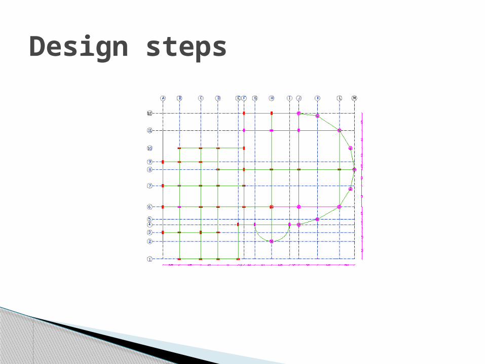
Design steps
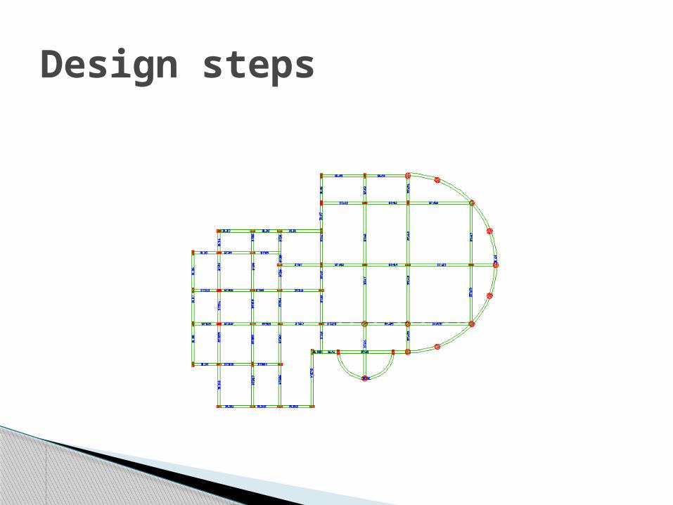
Design steps
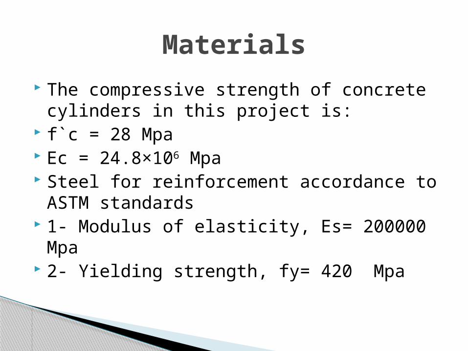
The compressive strength of concrete cylinders in this project is:
f`c = 28 Mpa Ec = 24.8×10⁶ Mpa Steel for reinforcement accordance to ASTM
standards 1- Modulus of elasticity, Es= 200000 Mpa 2- Yielding strength, fy= 420 Mpa
Materials
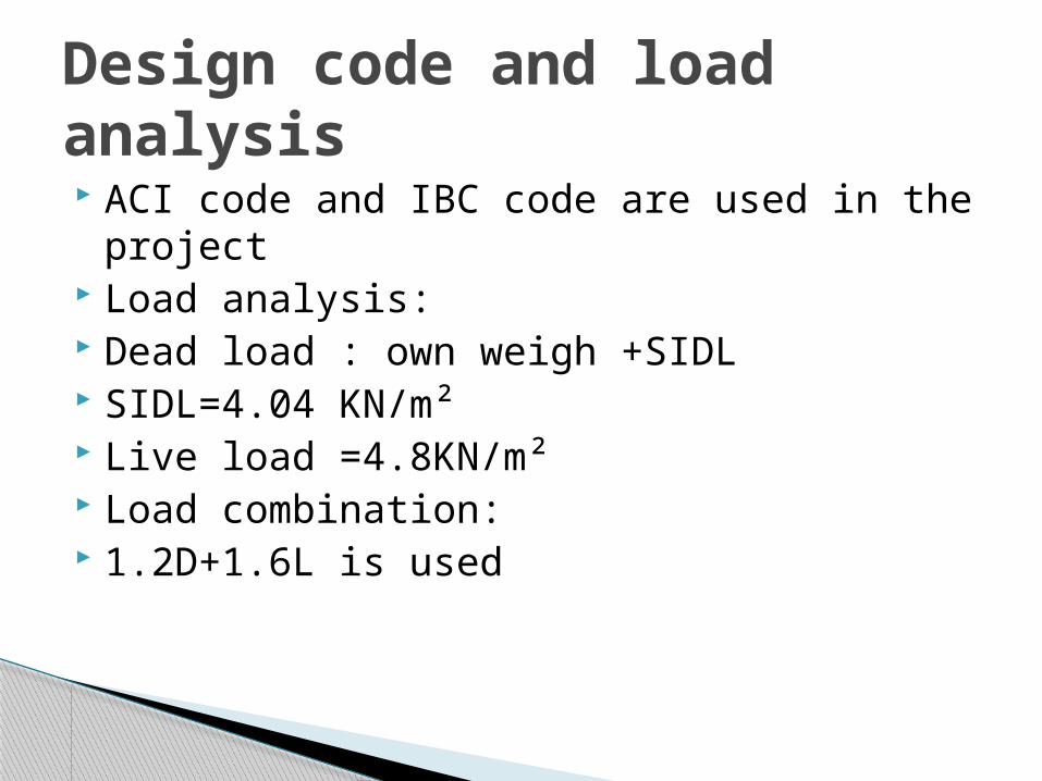
ACI code and IBC code are used in the project
Load analysis: Dead load : own weigh +SIDL SIDL=4.04 KN/m² Live load =4.8KN/m² Load combination: 1.2D+1.6L is used
Design code and load analysis

The preliminary design includes all the hand calculation we made in the project , the preliminary design is very important process because it's define the preliminary loads and dimensions that need to be entered in the SAP program , and help understand the structure.
The preliminary design is not precise but should be within accepted tolerance .
Chapter two: preliminary design
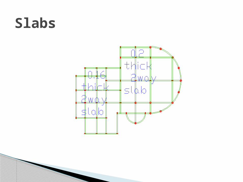
Slab system in the project is two way solid slab ,and it's divided in two areas right (Part A) and left (Part B ) each has different slab thickness and different dimensions for beams
Design of slabs
Slabs
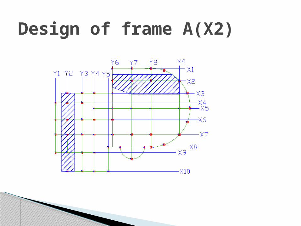
Design of frame A(X2)


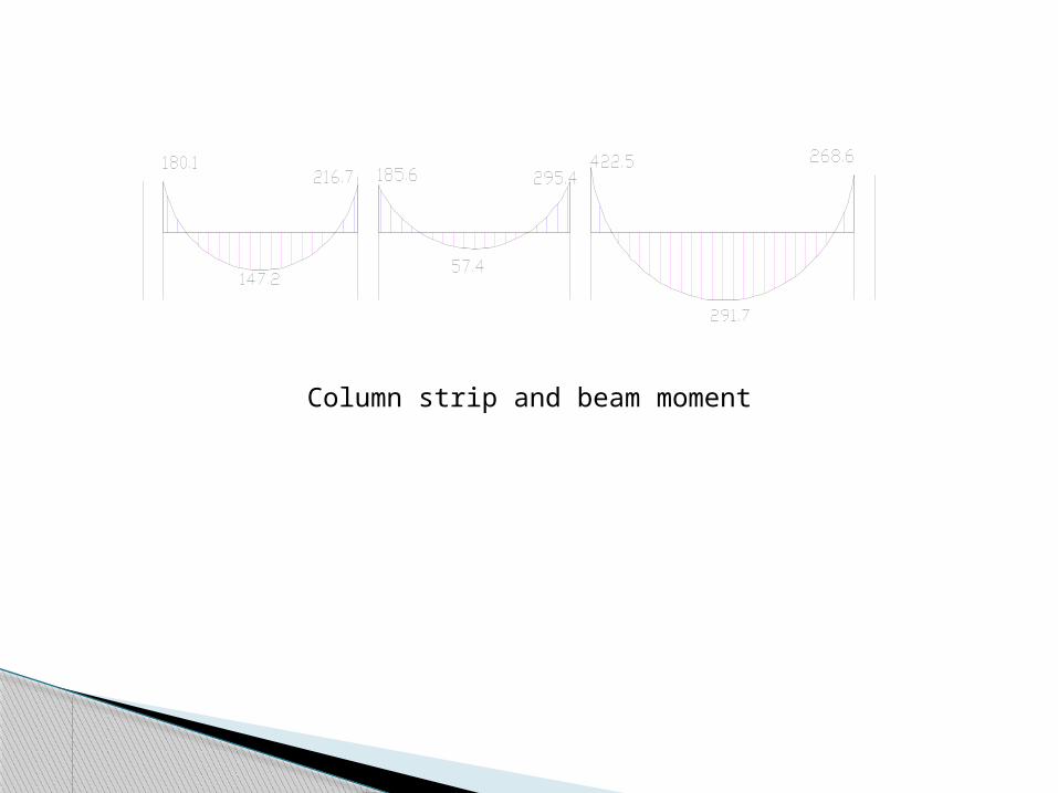
Column strip and beam moment
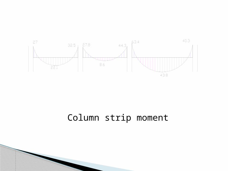
Column strip moment

Middle strip moment
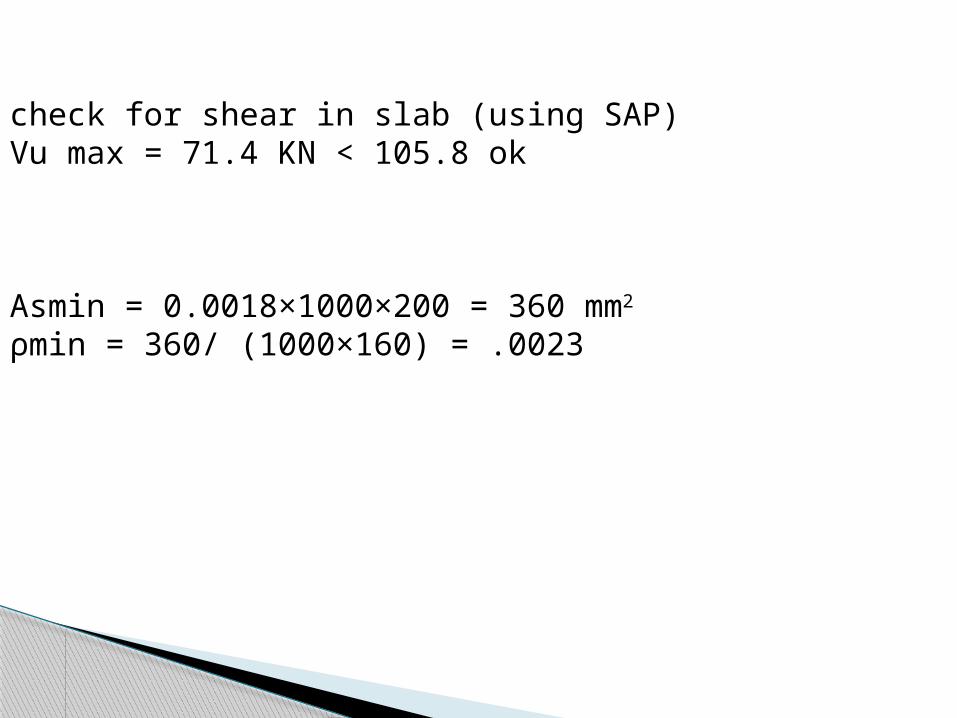
check for shear in slab (using SAP)Vu max = 71.4 KN < 105.8 ok
Asmin = 0.0018×1000×200 = 360 mm2
ρmin = 360/ (1000×160) = .0023
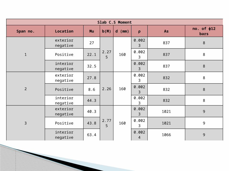
Slab C.S Moment
Span no. Location Mu b(M) d (mm) ρ As no. of ɸ12 bars
1
exterior negative 27
2.275 160
0.0023 837 8
Positive 22.1 0.0023 837 8
interior negative 32.5 0.0023 837 8
2
exterior negative 27.8
2.26 160
0.0023 832 8
Positive 8.6 0.0023 832 8
interior negative 44.3 0.0023 832 8
3
exterior negative 40.3
2.775 160
0.0023 1021 9
Positive 43.8 0.0023 1021 9
interior negative 63.4 0.0024 1066 9
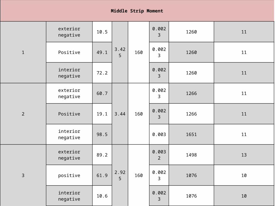
Middle Strip Moment
1
exterior negative 10.5
3.425 160
0.0023 1260 11
Positive 49.1 0.0023 1260 11
interior negative 72.2 0.0023 1260 11
2
exterior negative 60.7
3.44 160
0.0023 1266 11
Positive 19.1 0.0023 1266 11
interior negative 98.5 0.003 1651 11
3
exterior negative 89.2
2.925 160
0.0032 1498 13
positive 61.9 0.0023 1076 10
interior negative 10.6 0.0023 1076 10
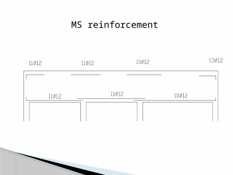
MS reinforcement
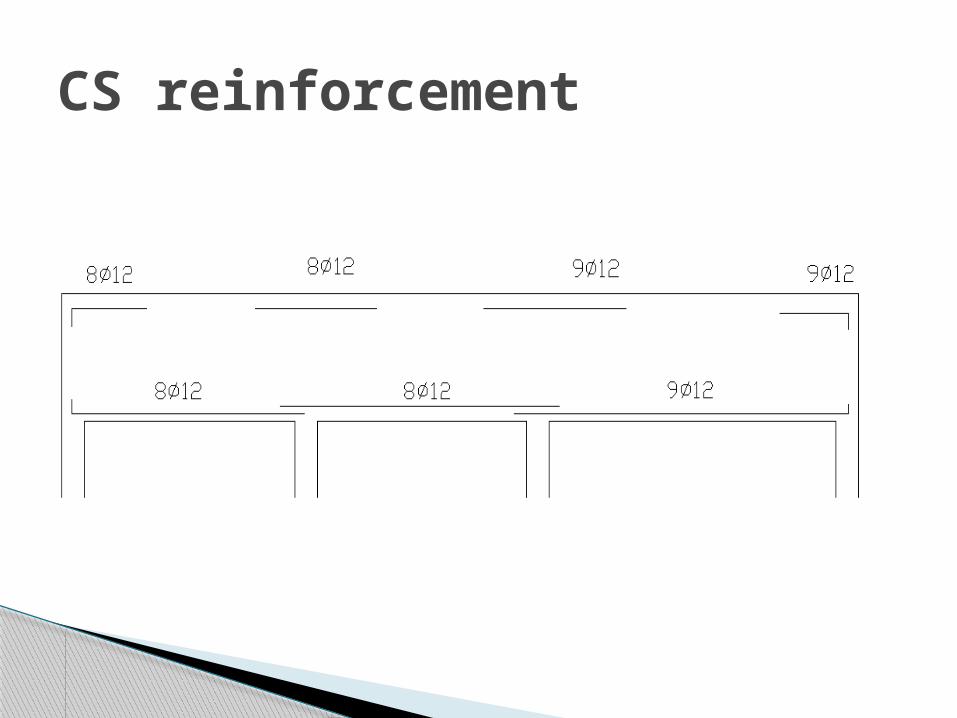
CS reinforcement
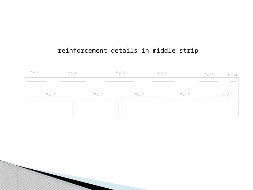
reinforcement details in middle strip

reinforcement details in column strip
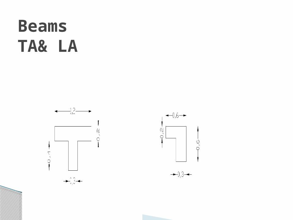
BeamsTA& LA
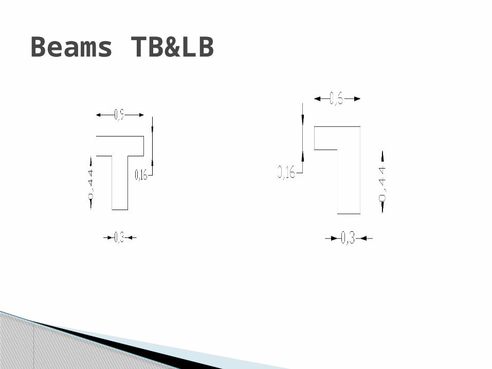
Beams TB&LB
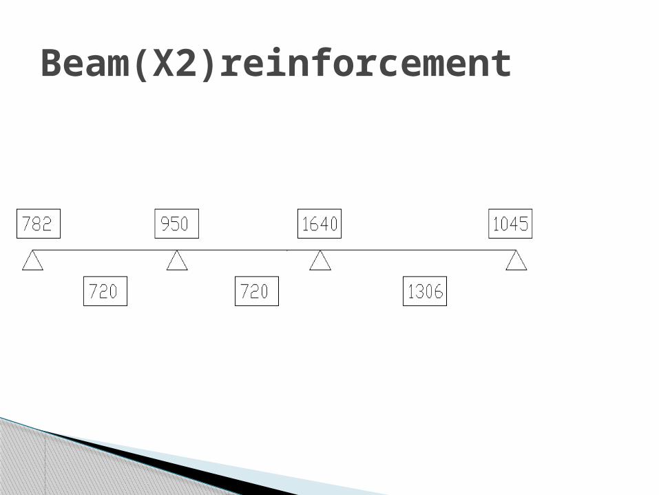
Beam(X2)reinforcement
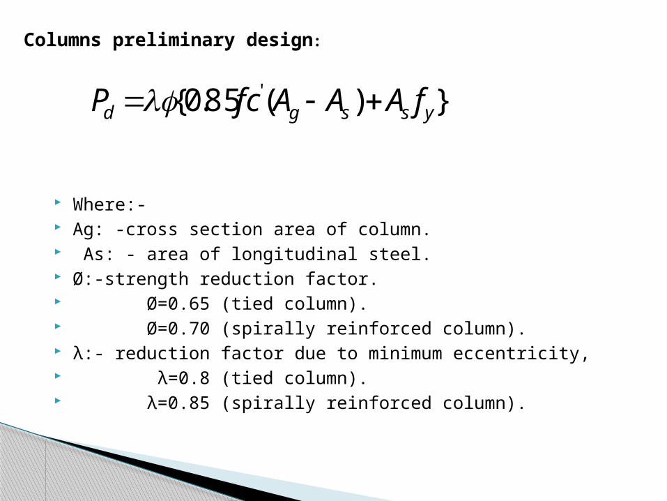
Where:- Ag: -cross section area of column. As: - area of longitudinal steel. Ø:-strength reduction factor. Ø=0.65 (tied column). Ø=0.70 (spirally reinforced column). λ:- reduction factor due to minimum eccentricity, λ=0.8 (tied column). λ=0.85 (spirally reinforced column).
})(85.0{ 'yssgd fAAAfcP
Columns preliminary design:
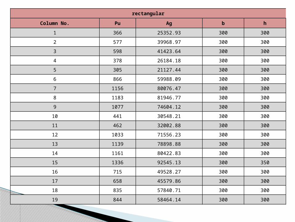
rectangular
Column No. Pu Ag b h
1 366 25352.93 300 300
2 577 39968.97 300 300
3 598 41423.64 300 300
4 378 26184.18 300 300
5 305 21127.44 300 300
6 866 59988.09 300 300
7 1156 80076.47 300 300
8 1183 81946.77 300 300
9 1077 74604.12 300 300
10 441 30548.21 300 300
11 462 32002.88 300 300
12 1033 71556.23 300 300
13 1139 78898.88 300 300
14 1161 80422.83 300 300
15 1336 92545.13 300 350
16 715 49528.27 300 300
17 658 45579.86 300 300
18 835 57840.71 300 300
19 844 58464.14 300 300
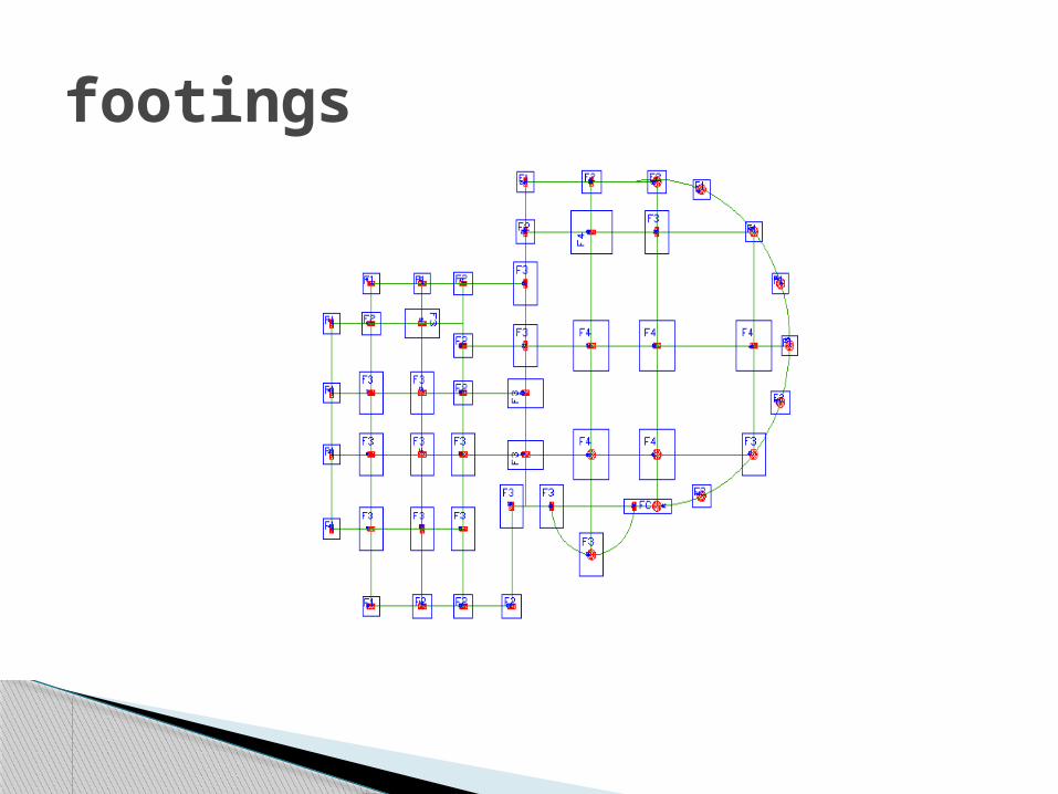
footings
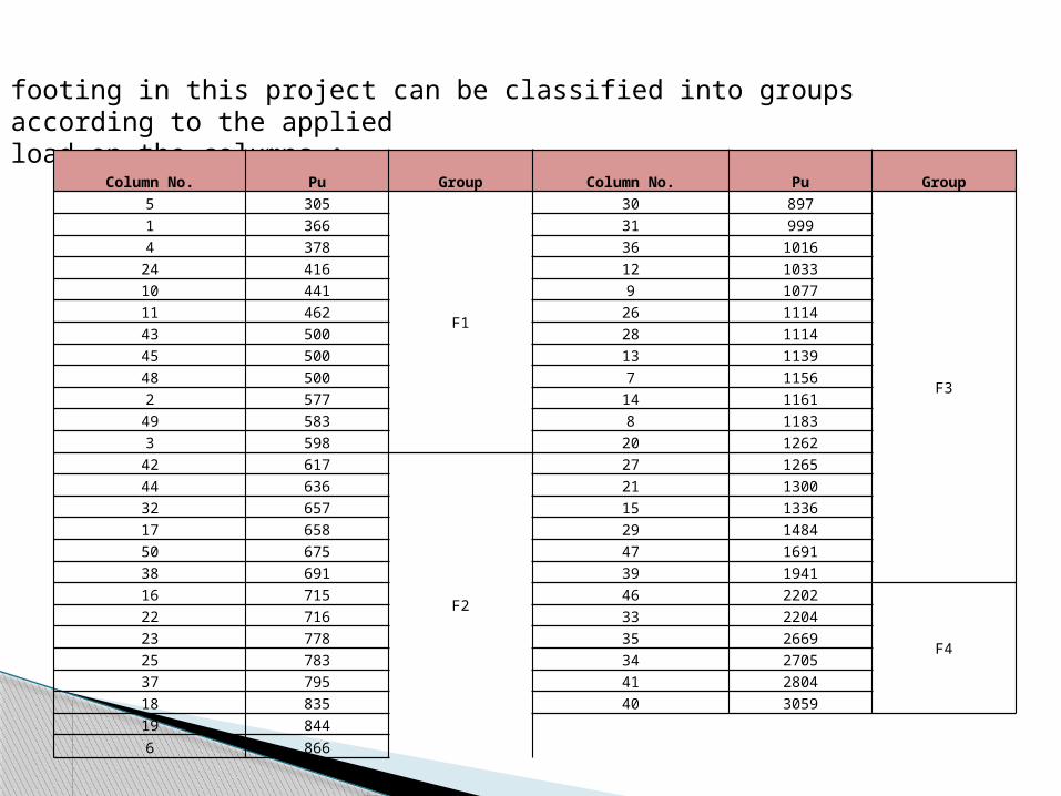
footing in this project can be classified into groups according to the applied load on the columns :
Column No. Pu Group Column No. Pu Group
5 305
F1
30 897
F3
1 366 31 999
4 378 36 1016
24 416 12 1033
10 441 9 1077
11 462 26 1114
43 500 28 1114
45 500 13 1139
48 500 7 1156
2 577 14 1161
49 583 8 1183
3 598 20 1262
42 617
F2
27 1265
44 636 21 1300
32 657 15 1336
17 658 29 1484
50 675 47 1691
38 691 39 1941
16 715 46 2202
F4
22 716 33 2204
23 778 35 2669
25 783 34 2705
37 795 41 2804
18 835 40 3059
19 844
6 866
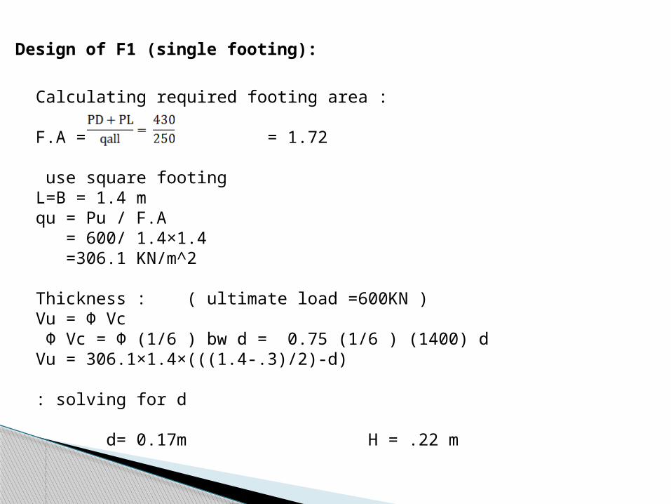
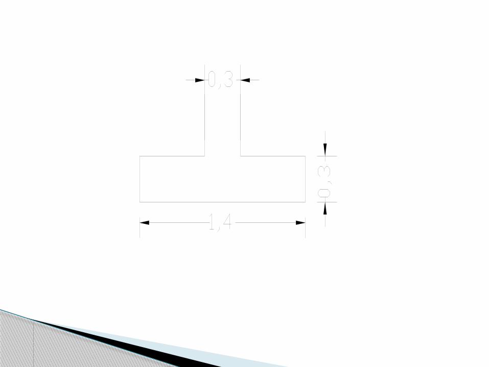
Design of F1 (single footing):
Calculating required footing area :
F.A = = 1.72
use square footingL=B = 1.4 mqu = Pu / F.A = 600/ 1.4×1.4 =306.1 KN/m^2
Thickness : ( ultimate load =600KN )Vu = Φ Vc
Φ Vc = Φ (1/6 ) bw d = 0.75 (1/6 ) (1400) d Vu = 306.1×1.4×(((1.4-.3)/2)-d)
solving for d:
d= 0.17m H = .22 m
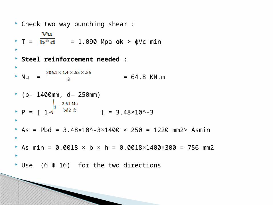
Check two way punching shear :
T = = 1.090 Mpa ok > фVc min Steel reinforcement needed : Mu = = 64.8 KN.m
(b= 1400mm, d= 250mm)
Ρ = [ 1- ] = 3.48×10^-3 As = Ρbd = 3.48×10^-3×1400 × 250 = 1220 mm2> Asmin As min = 0.0018 × b × h = 0.0018×1400×300 = 756 mm2 Use (6 Φ 16) for the two directions
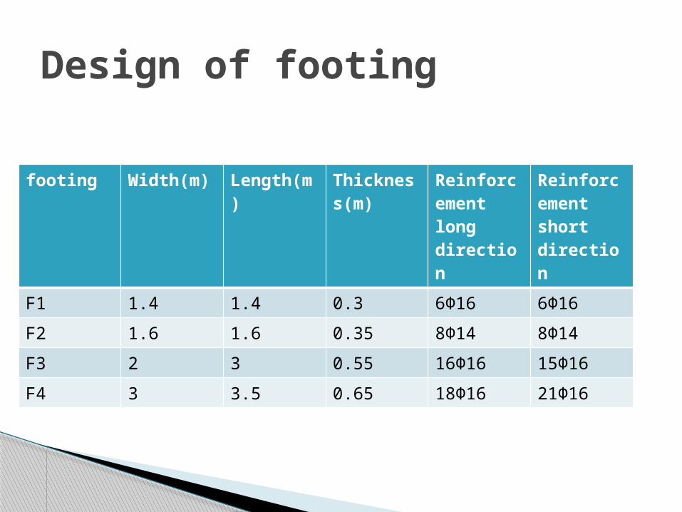
footing Width(m)
Length(m)
Thickness(m)
Reinforcement long direction
Reinforcement short direction
F1 1.4 1.4 0.3 6Φ16 6Φ16
F2 1.6 1.6 0.35 8Φ14 8Φ14
F3 2 3 0.55 16Φ16 15Φ16
F4 3 3.5 0.65 18Φ16 21Φ16
Design of footing
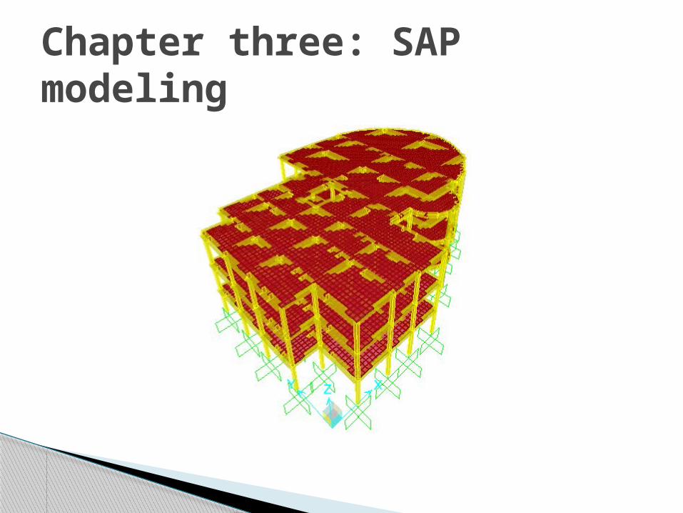
Chapter three: SAP modeling
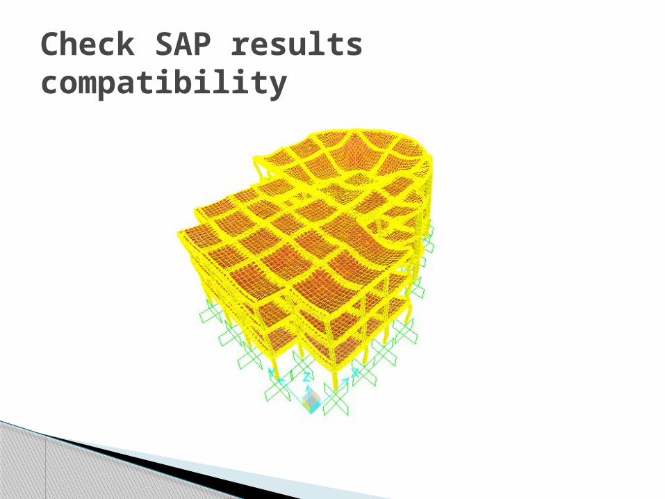
Check SAP resultscompatibility
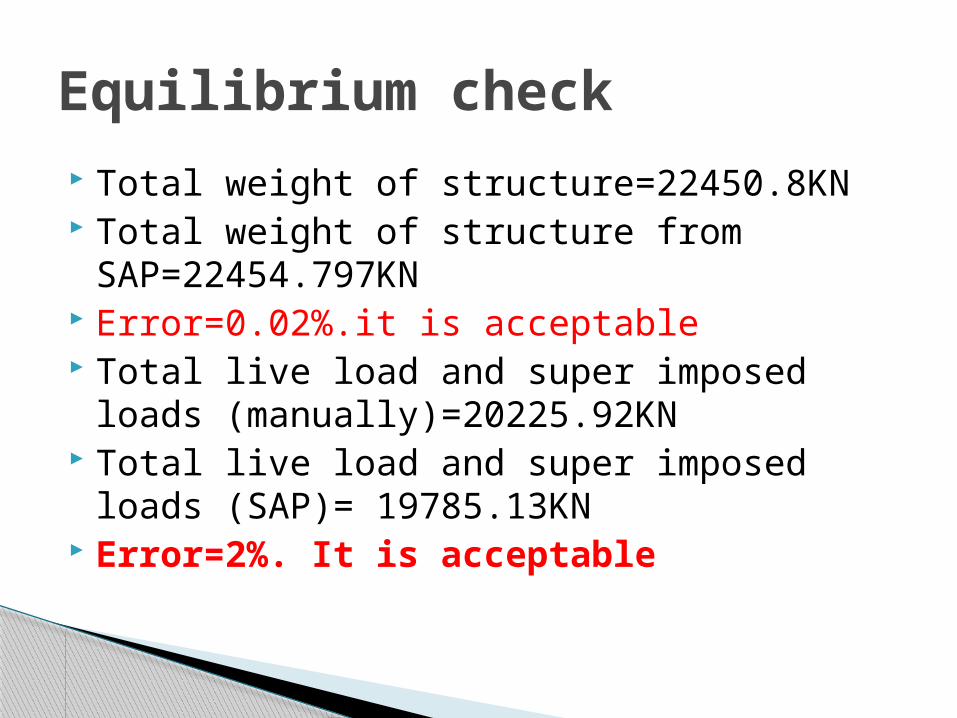
Total weight of structure=22450.8KN Total weight of structure from
SAP=22454.797KN Error=0.02%.it is acceptable Total live load and super imposed loads
(manually)=20225.92KN Total live load and super imposed loads
(SAP)= 19785.13KN Error=2%. It is acceptable
Equilibrium check
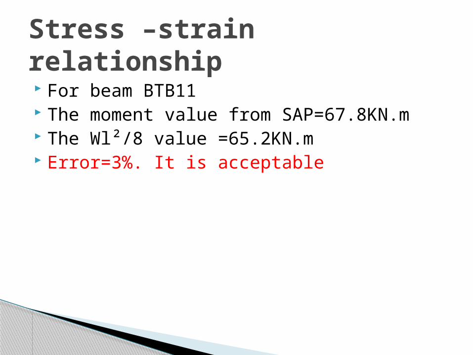
For beam BTB11 The moment value from SAP=67.8KN.m The Wl²/8 value =65.2KN.m Error=3%. It is acceptable
Stress –strain relationship

The maximum deflection manually =34.42mm
The maximum deflection from SAP=7.8mm So that the deflection check is ok
Check deflection
Since the building is located beside a gas station (12 meter far away from the nearest
point) a practical approach of assumed explosion in one of the gasoline tanks has
been developed. The loads on columns and slabs were estimated and 3D modeling of
the structure and loads using SAP2000 has been created.
Chapter four: blast analysis
SAP resultsslab reinforcement
Explosion and air blast loading
An explosion is defined as a large-scale, rapid and sudden release of energy
The threat for an explosion can be defined by two equally important elements, the explosive size, or charge weight W, and the standoff distance R between the blast source and the target


Prediction of blast pressure
Explosion point
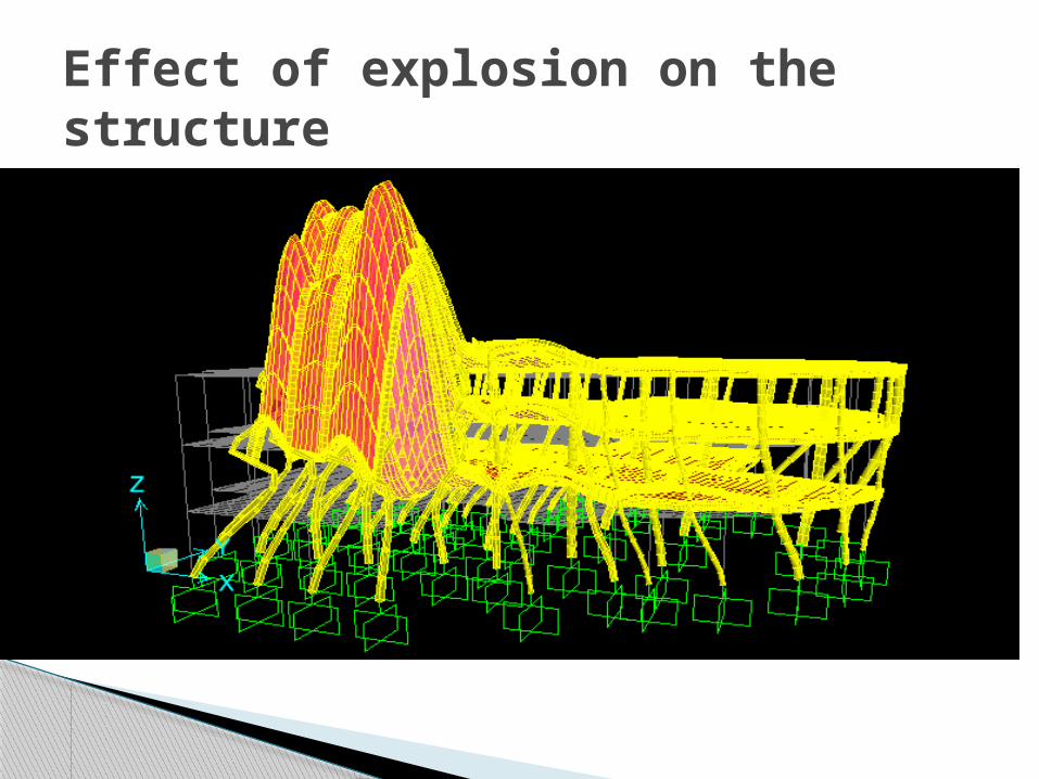
Effect of explosion on the structure
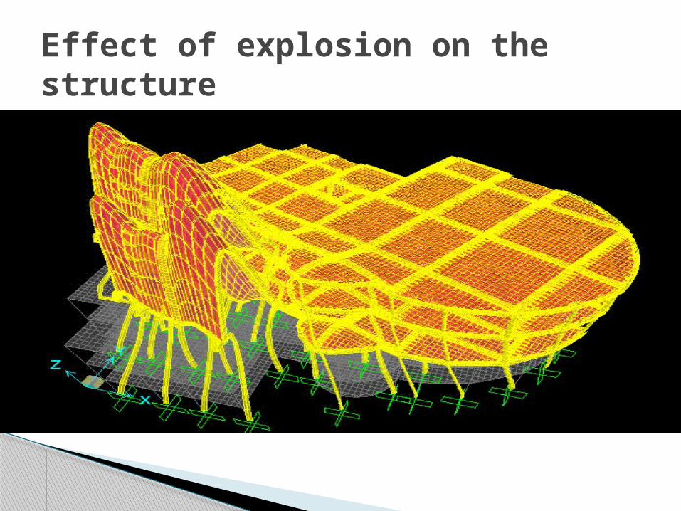
Effect of explosion on the structure
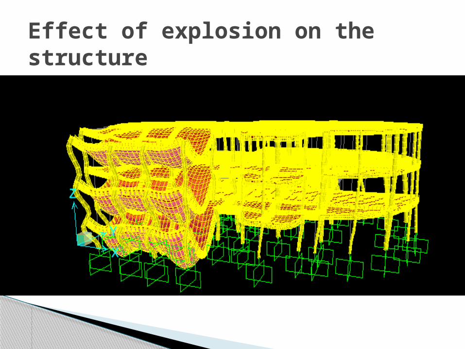
Effect of explosion on the structure
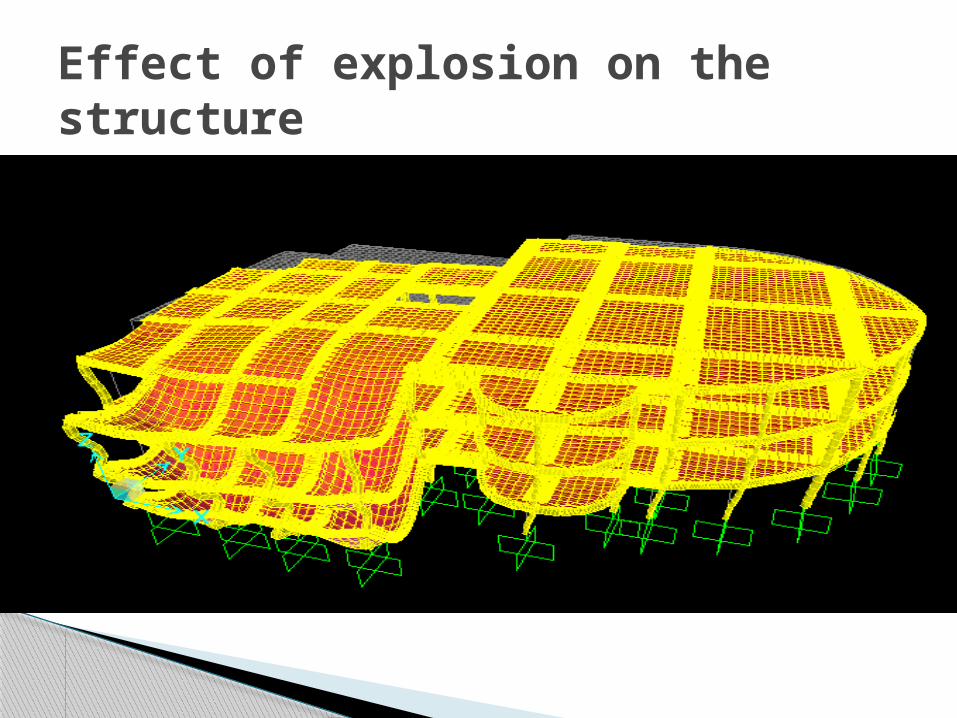
Effect of explosion on the structure
The gas station should be far from the building by at least 60 m
The glass interface is not recommended because the glass has a high thermal coefficient .
Replace the glass interface by shear walls
Recommendation