An ITE Proposed Recommended Practice - US EPA€¦ · An ITE Proposed Recommended Practice ... This...
221
An ITE Proposed Recommended Practice Context Sensitive Solutions i n Designing Major Urban Thoroughfares for Walkable Communities
Transcript of An ITE Proposed Recommended Practice - US EPA€¦ · An ITE Proposed Recommended Practice ... This...

i
A n I T E P r o p o s e d R e c o m m e n d e d P r a c t i c e
Context Sensitive Solutions in Designing Major Urban Thoroughfares
for Walkable Communities

ii
The Institute of Transportation Engineers is an international educational and scientifi c association of transportation pro-fessionals who are responsible for meeting mobility and safety needs. ITE facilitates the application of technology and scientifi c principles to research, planning, functional design, implementation, operation, policy development and man-agement for any mode of transportation. Through its products and services, ITE promotes professional development of its members, supports and encourages education, stimulates research, develops public awareness programs and serves as a conduit for the exchange of professional information.
Founded in 1930, ITE serves as a gateway to knowledge and advancement through meetings, seminars and publications and through its network of nearly 17,000 members working in more than 92 countries. ITE also has more than 70 local and regional chapters and more than 120 student chapters that provide additional opportunities for information exchange, participation and networking. To learn more about ITE and our services, visit www.ite.org or call +1 202-289-0222.
Institute of Transportation Engineers1099 14th Street, NW, Suite 300 WestWashington, DC 20005 USATelephone: +1 202-289-0222Fax: +1 202-289-7722ITE on the Web: www.ite.org
Sponsored by:
Offi ce of InfrastructureFederal Highway Administration400 7th Street, SW Washington, DC 20590
Offi ce of Planning, Environment and RealtyFederal Highway Administration400 7th Street, SW Washington, DC 20590
Offi ce of Policy, Economics and Innovation DevelopmentU.S. EPA1200 Pennsylvania Ave NW Mailcode 1807TWashington, DC 20460
Notices:This document is disseminated under the sponsorship of the Department of Transportation in the interest of information exchange. The U.S. Government assumes no liability for its contents or the use thereof. This report does not constitute a standard, specifi cation, or regulation. The U.S. Government and ITE do not endorse products or manufacturers. Trade and manufacturers’ names appear in this report only because they are considered essential to the object of the document.
This project was partially funded by a cooperative agreement from the Environmental Protection Agency’s Development, Community and Environment Division.
RP-036© 2006 Institute of Transportation Engineers. All rights reserved.500/GP/JS/0306
Printed in the United States of AmericaISBN No: 1-933452-11-0

iii
Table of Contents
Part 1: Introduction
Chapter 1. Foundation ......................................................................................................................................3Purpose ........................................................................................................................................................... 3Objectives ......................................................................................................................................................... 3Focus of Report ................................................................................................................................................ 3Organization..................................................................................................................................................... 4Who Should Use Report .................................................................................................................................... 4Introduction to CSS ........................................................................................................................................... 4Conventional Process Versus CSS ..................................................................................................................... 9Principles of CSS ............................................................................................................................................... 9Principles for CSS in Urban Walkable Communities .......................................................................................... 10CSS to Create Walkable Communities .............................................................................................................. 10Relationship to Other Guidance....................................................................................................................... 11Key Terms and New Concepts .......................................................................................................................... 12Works Cited .................................................................................................................................................... 12References for Further Reading ....................................................................................................................... 12
Part 2: Planning
Chapter 2. Planning and Developing Context Sensitive Urban Thoroughfares....................................... 17Purpose .......................................................................................................................................................... 17Objectives ....................................................................................................................................................... 17CSS in the Transportation Planning Process ...................................................................................................... 17CSS in the Project Development Process .......................................................................................................... 21References for Further Reading ....................................................................................................................... 23
Chapter 3. Network and Corridor Planning ................................................................................................. 25Purpose .......................................................................................................................................................... 25Objectives ....................................................................................................................................................... 25Introduction .................................................................................................................................................... 25CSS in Network Planning ................................................................................................................................ 26Applying CSS in Network Planning .................................................................................................................. 27CSS Considerations for Effective Network Planning ......................................................................................... 28CSS Guidelines for Network Planning and Design ............................................................................................ 30Applying CSS in Urban Corridor Thoroughfare Planning .................................................................................. 32CSS Example in Corridor Planning – Developing Evaluation Criteria ................................................................. 36Works Cited .................................................................................................................................................... 38References for Further Reading ....................................................................................................................... 38
Chapter 4. A Framework for Urban Thoroughfare Design ......................................................................... 41Purpose .......................................................................................................................................................... 41Objectives ....................................................................................................................................................... 41Introduction .................................................................................................................................................... 41Features that Create Context .......................................................................................................................... 42Context Zones ................................................................................................................................................ 45

iv
Selecting a Context Zone in Thoroughfare Design ............................................................................................ 46Thoroughfare Types ......................................................................................................................................... 46Works Cited .................................................................................................................................................... 50References for Further Reading ....................................................................................................................... 50
Part 3: Design
Chapter 5. Thoroughfare Design Process ................................................................................................. 55Purpose .......................................................................................................................................................... 55Objectives ...................................................................................................................................................... 55Defi nitions ...................................................................................................................................................... 55Overview of the Design Process ....................................................................................................................... 57Flexibility in Application of Design Criteria ....................................................................................................... 61Design Process in Constrained Right-of-Way .................................................................................................... 62Works Cited .................................................................................................................................................... 63
Chapter 6. Thoroughfare Design for Urban Areas ................................................................................. 65Purpose ......................................................................................................................................................... 65Objectives ....................................................................................................................................................... 65Basis for Thoroughfare Design Examples .......................................................................................................... 65General Thoroughfare Design for Urban Areas ................................................................................................. 65Design Examples............................................................................................................................................. 68Design Example #1: Creating a Retail-Oriented Main Street ............................................................................. 69Design Example #2: Transforming a Suburban Arterial ...................................................................................... 73Design Example #3: High Capacity Thoroughfare in Urbanizing Area ................................................................ 78Design Example #4: Central Business District Four to Three-Lane Conversion .................................................... 84
Chapter 7. Design Controls ......................................................................................................................... 89Purpose ......................................................................................................................................................... 89Objectives ....................................................................................................................................................... 89Introduction .................................................................................................................................................... 89Design Controls Defi ned by AASHTO ............................................................................................................... 89Differences from Conventional Practice ........................................................................................................... 90Additional Controls to Consider in Thoroughfare Design .................................................................................. 92Works Cited .................................................................................................................................................... 93
Chapter 8. Roadside Design Guidelines ................................................................................................... 95Purpose .......................................................................................................................................................... 95Objectives ....................................................................................................................................................... 95Introduction .................................................................................................................................................... 95The Urban Roadside: Uses and Activities .......................................................................................................... 96Design Principles ............................................................................................................................................ 97Design Guidance .......................................................................................................................................... 102Roadside Width and Functional Requirements ..................................................................................... 103Background and Purpose .............................................................................................................................. 103General Principles and Considerations ........................................................................................................... 103Edge Zone Principles and Considerations ....................................................................................................... 104Furnishings Zone Principles and Considerations ............................................................................................. 105Throughway Zone Principles and Considerations ............................................................................................ 106

v
Frontage Zone Principles and Considerations ................................................................................................. 106Driveway Crossing Principles and Considerations ........................................................................................... 106Recommended Practice ................................................................................................................................. 108Additional Guidelines .................................................................................................................................... 108Justifi cation .................................................................................................................................................. 111Works Cited .................................................................................................................................................. 112References for Further Reading ..................................................................................................................... 112
Chapter 9. Traveled Way Design Guidelines .......................................................................................... 113Purpose ........................................................................................................................................................ 113Objectives ..................................................................................................................................................... 113Introduction .................................................................................................................................................. 113Design Considerations .................................................................................................................................. 114Design Guidance .......................................................................................................................................... 118Lane Width ................................................................................................................................................. 118Background and Purpose .............................................................................................................................. 118General Principles and Considerations .......................................................................................................... 118Recommended Practice ................................................................................................................................. 120Medians ..................................................................................................................................................... 120Background and Purpose .............................................................................................................................. 120General Principles and Considerations ........................................................................................................... 121Recommended Practice ................................................................................................................................ 122Additional Guidelines .................................................................................................................................... 122Trees and Landscaping in Medians ................................................................................................................ 122Justifi cation .................................................................................................................................................. 124Bicycle Lanes ............................................................................................................................................. 124Background and Purpose .............................................................................................................................. 124General Principles and Considerations ........................................................................................................... 126Recommended Practice ................................................................................................................................. 130On-Street Parking Confi guration and Width ......................................................................................... 130Background and Purpose .............................................................................................................................. 130General Principles and Considerations ........................................................................................................... 131Recommended Practice ................................................................................................................................. 132Additional Guidelines .................................................................................................................................... 132Justifi cation .................................................................................................................................................. 134Transition Design ...................................................................................................................................... 134Background and Purpose .............................................................................................................................. 134Recommended Practice ................................................................................................................................ 134Additional Guidelines .................................................................................................................................... 134Midblock Crossings .................................................................................................................................. 134Background and Purpose .............................................................................................................................. 134General Principles and Considerations ........................................................................................................... 136Recommended Practice ................................................................................................................................. 137Justifi cation .................................................................................................................................................. 137Pedestrian Refuge Islands ....................................................................................................................... 140Background and Purpose .............................................................................................................................. 140General Considerations ................................................................................................................................. 140Recommended Practice ................................................................................................................................. 141Justifi cation .................................................................................................................................................. 141

vi
Midblock Bus Stops ................................................................................................................................. 141Background and Purpose .............................................................................................................................. 141General Principles and Considerations ........................................................................................................... 141Recommended Practice ................................................................................................................................. 144Justifi cation .................................................................................................................................................. 148Special Consideration with Snow Removal........................................................................................... 148Background and Purpose .............................................................................................................................. 148General Principle .......................................................................................................................................... 149Recommended Practice ................................................................................................................................ 149Justifi cation .................................................................................................................................................. 150Works Cited .................................................................................................................................................. 150References for Further Reading ..................................................................................................................... 150
Chapter 10. Intersection Design Guidelines .......................................................................................... 153Introduction .................................................................................................................................................. 153Objectives ..................................................................................................................................................... 154General Principles and Considerations .......................................................................................................... 154Design Guidance ....................................................................................................................................... 158Intersection Geometry ................................................................................................................................... 158General Intersection Layout ........................................................................................................................... 158General Principles and Considerations ........................................................................................................... 159Curb Return Radii ..................................................................................................................................... 161Background and Purpose .............................................................................................................................. 161General Principles and Considerations ........................................................................................................... 161Recommended Practice ................................................................................................................................ 162Justifi cation .................................................................................................................................................. 164Channelized Right-Turns .......................................................................................................................... 164Background and Purpose .............................................................................................................................. 164General Principles and Considerations ........................................................................................................... 164Recommended Practice ................................................................................................................................. 165Modern Roundabouts .............................................................................................................................. 166Background and Purpose .............................................................................................................................. 166General Principles and Considerations ........................................................................................................... 167Recommended Practice ................................................................................................................................. 169Justifi cation .................................................................................................................................................. 169Pedestrian Treatments at Intersections—Crosswalks .......................................................................... 169Background and Purpose .............................................................................................................................. 169General Principles and Considerations ........................................................................................................... 170Recommended Practice ................................................................................................................................. 171Justifi cation .................................................................................................................................................. 171Curb Extensions ....................................................................................................................................... 172Background and Purpose .............................................................................................................................. 172General Principles and Considerations ........................................................................................................... 172Recommended Practice ................................................................................................................................ 174Justifi cation .................................................................................................................................................. 174Bicycle Lane Treatment at Intersections ................................................................................................ 175Background and Purpose .............................................................................................................................. 175General Principles and Considerations ........................................................................................................... 175Recommended Practice ................................................................................................................................. 175

vii
Justifi cation .................................................................................................................................................. 175Bus Stops at Intersections ....................................................................................................................... 176Background and Purpose .............................................................................................................................. 176Recommended Practice ................................................................................................................................. 176Works Cited .................................................................................................................................................. 179References for Further Reading ..................................................................................................................... 180
Chapter 11. Thoroughfares in Single Land Use or Vehicle Mobility Priority Areas ................... 181Purpose ....................................................................................................................................................... 181Objectives ..................................................................................................................................................... 181Single Land Use Categories ........................................................................................................................... 181Determining Thoroughfare Cross-Sections ...................................................................................................... 183Applicability of Report to Vehicle Mobility Priority Thoroughfare Design .......................................................... 184Vehicle Mobility Priority Thoroughfare Design Parameters .............................................................................. 184Works Cited .................................................................................................................................................. 185
Case Studies
Case Study: Arterial Avenue in Urban Center ...................................................................................................... 190Case Study: Arterial Boulevard in Urban Center Context .................................................................................... 194Case Study: Arterial Avenue in Urban Center Context ........................................................................................ 200Case Study: Arterial Avenue in General Urban/Urban Center ............................................................................... 206Case Study: Arterial Avenue in General Urban Context ...................................................................................... 210
Appendices
Appendix I: Glossary of Terms .................................................................................................................. 217
Appendix II: Bibliography.......................................................................................................................... 223

ix
Preface and Acknowledgements
This report is published as a proposed recommended practice of the Institute of Transportation Engineers (ITE). As such, it is to be considered in its proposed form, but is subject to change after receipt and consideration of suggestions from those who have reviewed the report. Readers are encouraged to submit written suggestions for improving this report to:
Institute of Transportation EngineersAttention: Lisa Fontana Tierney1099 14th Street, NW, Suite 300 WestWashington, DC 20005Fax +1 202-289-07722 [email protected]
Written suggestions should be received at the above address no later than December 31, 2006 to ensure consideration for incorporation into the fi nal recommended practice report.
ITE wishes to thank the Federal Highway Administration’s Offi ce of Infrastructure, Offi ce of Planning, Environ-ment and Realty and the Environmental Protection Agency’s Offi ce of Policy, Economics and Innovation Devel-opment for fi nancially supporting this work effort and providing leadership and guidance in the development of this report.
This report was developed through a partnership with ITE and the Congress for the New Urbanism (CNU) and is the result of several years of concerted effort by dedicated volunteers, including ITE and CNU members and many other interested parties. ITE wishes to thank the members of each of the following committees for their respective roles in the preparation of this report.
The project management team played an essential role in the identifi cation, development and refi nement of content, including numerous detailed reviews throughout the development process. The members of the project management team were:
Brian S. Bochner (F), Texas Transportation InstitutePhilip J. Caruso (F), ITE
Lisa Fontana Tierney (M), ITEChristopher V. Forinash (A), EPA
Ellen Greenberg, Freedman, Tung & BottomleyHeather Smith, CNU
Jon T. Obenberger (M), FHWAHarold E. Peaks, FHWA

x
A multidisciplinary steering committee, including policy and technical advisory committees, was responsible for general project oversight. The policy advisory committee was responsible for providing overall vision and direc-tion, while the technical advisory committee provided guidance and review of technical content. The members of the policy and technical advisory committees were:
POLICY ADVISORY COMMITTEE TECHNICAL ADVISORY COMMITTEE
Geoff Anderson Chester E. Chellman (M)Frances Banerjee Norman W. Garrick (A)
Bob BryantPeter CalthorpeAndres Duany
R. Marshall Elizer Jr. (F)Dwight A. HorneHal Kassoff (M)
Kenneth F. Kobetsky (M)Harold E. Peaks
Harry W. Taylor (M)
Richard A. Hall (F)Rodney W. Kelly (F) John N. LaPlante (F)
Marcy McInelly Peter Swift
Jeffrey Tumlin
This report was balloted and approved by a committee of individuals actively involved in the development of the report. The voting committee members included:
R. Marshall Elizer Jr. (F)Norman W. Garrick (A)
Richard A. Hall (F)Rodney W. Kelly (F)John N. LaPlante (F)
Danny C. Pleasant (F)Peter Swift
Jeffrey Tumlin
Endorsement for publication of this document as an ITE proposed recommended practice was provided by a recommended practice review panel consisting of individuals with an active interest and knowledge of context sensitive design. The following individuals were members of the panel:
Raymond E. Davis III (F) Cesar J. Molina Jr. (M)
Brian L. Ray Dennis E. Royer (M)
Dean A. SchreiberNikiforos Stamatiadis (M)
A consultant team, led by James M. Daisa (M), was responsible for creating and assembling all technical content. These efforts included development of the report’s organizational struc-
ture; identifi cation, research and development of case studies; and compilation, evaluation and incorporation of numerous comments in concert with direction provided by the project
management team. The consulting fi rms and their respective individuals were:KIMLEY-HORN AND ASSOCIATES INC.
James M. Daisa (M), Project ManagerMark J. Brown
Bruce E. Friedman (F) Roger B. Henderson (M)
Andrew C. HowardJohn Martin
Frederick W. Schwartz (M)
Deborah K. Fehr (A) Steve E. Lefton Nik Nikolaev
Michelle M. Olmsted (A)Patrick Ramos

xi
COMMUNITY, DESIGN + ARCHITECTURE
Phil EricksonKyla Burson
Thomas KronemeyerKendra Mitchell
Evelyn O’DonohueSam Zimmerman-Bergman
MEYER, MOHADDES ASSOCIATES INC.Frederick C. Dock (M)
UNIVERSITY OF MARYLAND
Reid Ewing (A)
Additional technical reviewers and commentators of draft versions of this report included:Bruce Appleyard
William R. Balentine (M)Timothy S. Bochum (M)
Scott Bradley Robert H. Brakman (M)
Dan E. Burden (M)Joseph C. Chester (M)
Payton ChungVivian D. Coleman (M)
Stephen J. Cote (A)Mike Davis
Ron DeNadaiSteven Elkins
Dan GallegherLucinda E. Gibson (M)
Toni GoldLewis G. Grimm (M)
Keith HinesTimothy T. Jackson (M)
Robert P. Jurasin (F)Tom Kloster (M)
Walter M. Kulash (M)John Lazarra
Elizabeth MacdonaldJoanna M. Musters (F)
Tracey NewsomeMatthew D. Ridgway (M)
Wilton A. Roberts (M)Otha J. Rogers (M)
Bob SchlictSamuel Seskin
Frank Spielberg (F)Lois E.L. Thibault
Dennis R. Toomey (M)Jerry Walters
Robert C. Wunderlich (F)
(Letters in parentheses indicate ITE member grade: A-Associate, M-Member, F-Fellow.)

1
P A R T 1
Introduction

3
Purpose
This report advances the successful use of context sensitive solutions (CSS) in the planning and design of major urban thoroughfares for walkable commu-nities. It provides guidance and demonstrates for practitioners how CSS concepts and principles may be applied in roadway improvement projects that are consistent with their physical settings.
CSS is the result of developing transportation proj-ects that serve all users and are compatible with the surroundings through which they pass—the commu-nity and environment. Successful CSS results from a collaborative, multidisciplinary and holistic approach to transportation planning and project development. CSS in the transportation planning or project devel-opment process identifi es objectives, issues and con-cerns based on stakeholder and community input at each level of planning and design (for example, network, corridor and project). This report provides guidance in how CSS principles may be considered and applied in the processes involved with planning and developing roadway improvements along urban thoroughfares.
As documented in Context-Sensitive Design Around the Country (TRB 2004), A Guide to Best Practices for Achieving Context Sensitive Solutions (TRB 2002) and other sources, the principles of CSS are successfully used in towns and cities as well as in rural areas. Agencies are transforming the current project development process to meet the expectations of all users and stakeholders. Integrating CSS principles into the project develop-ment process results in the consideration of a broad range of objectives and an attempt to balance these ob-jectives based on the needs and conditions specifi c to each project and its context. The use of CSS principles in the project development process is resulting in com-munity interests, user needs and environmental issues being considered early in the development of roadway improvement projects—specifi cally in defi ning the project’s purpose and need, and as appropriate, in other decisions in each phase of the project.
Objectives
The objectives of this report are to:1. Describe the principles of CSS and the benefi ts
and importance of CSS in transportation proj-ects;
2. Identify how CSS principles can be applied in the processes involved with planning and devel-oping roadway improvement projects on major urban thoroughfares;
3. Describe the relationship, compatibility and tradeoffs that may be appropriate when balanc-ing the needs of users, adjoining land uses, envi-ronment and community interests;
4. Present guidance on how to identify and select appropriate thoroughfare types and correspond-ing design parameters to best meet the needs of a particular context; and
5. Provide criteria for specifi c roadway elements along with guidance on balancing stakeholder, community and environmental needs and con-straints in roadway improvement projects.
Focus of Report
This report provides guidance for the development of improvement projects on major urban thorough-fares, facilities that are typically classifi ed as arterial and collector roadways in urbanized areas. While CSS is applicable to all types of transportation facilities, the guidelines in this report exclude high-speed lim-ited access facilities (including freeways, expressways and parkways) and local streets. The report’s chap-ters are focused on applying the principles of CSS in transportation planning and in the design of roadway improvement projects in places where community objectives support walkable communities—compact development, mixed land uses and support for pedes-trians and bicyclists, whether it already exists or is a goal for the future. Many of the principles, concepts and design guidelines are directly applicable to urban thoroughfares in other contexts.
1 C h a p t e r
Foundation

4
The principles, concepts and design criteria pre-sented in this report are applicable to transporta-tion planning as well as to thoroughfare design, and to construction and maintenance. The traditional term “thoroughfare” is used in this report instead of conventional names (street, roadway, or highway) to distinguish lower speed urban roadways from other types of roadways, and because some conventional names are used in this report to defi ne different types of thoroughfares. For purposes of this report, lower speed is defi ned as a range of operating speeds from 25 to 35 mph, and higher speed is defi ned as 40 to 45 mph.
This report addresses the controlling elements of thoroughfare design, presents a context-based design process within the project development framework and provides specifi c design guidelines for the various elements that comprise the major urban thorough-fare.
Organization
This report is divided into three parts: introduc-tion, planning and design. There are eleven chapters, with Chapter 1 being the introduction, Chapters 2 through 4 addressing CSS and the planning and proj-ect development process, and Chapters 5 through 11 addressing the thoroughfare design process and spe-cifi c design criteria. Table 1.1 lists the chapters and provides an overview of the material that is addressed in each chapter.
Chapter 6 provides general design parameters and example designs for major urban thoroughfares with speeds up to 35 mph, in areas with high levels of pe-destrian, bicycle and transit activity. Chapter 11 pro-vides general design parameters for thoroughfares in-tended to operate at 40 to 45 mph in areas of lower multimodal activity. Design guidelines in Chapters 8 through 10 focus on the design of lower speed thor-oughfares but much of this guidance is also applicable to the higher speed facilities addressed in Chapter 11.
Who Should Use Report
This report is for practitioners and stakeholders in-volved in the planning and design of major urban thoroughfares for walkable communities. Users are encouraged to consider the principles and guidelines in this report in conjunction with applicable local policies and standards. Table 1.2 presents many of the intended users and their responsibilities where CSS principles may be considered. Each user listed in Table 1.2 represents a different set of stakehold-ers, which brings different perspectives and respon-sibilities to the transportation planning and project development processes to best meet the needs of the stakeholders. However, all users may benefi t from an understanding of CSS principles and how they might be integrated into their work.
Introduction to CSS
What is CSS?CSS is a different way to approach the planning and de-sign of transportation projects. It is a process of balanc-ing the competing needs of many stakeholders starting in the earliest stages of project development. It is also fl exibility in the application of design controls, guide-lines and standards to design a facility that is safe for all users regardless of the mode of travel they choose.
There are many defi nitions of CSS (see sidebar for example defi nitions from state DOTs) but they share a common set of tenets:1
• “Balance safety, mobility, community and envi-ronmental goals in all projects;
• Involve the public and stakeholders early and continuously throughout the planning and project development process;
• Use an interdisciplinary team tailored to project needs;
• Address all modes of travel;
• Apply fl exibility inherent in design standards; and
• Incorporate aesthetics as an integral part of good design.”
1 Principles from the Minnesota Department of Transporta-tion as published on the University of Minnesota’s Center for Transportation Studies Web site www.cts.umn.edu/education/csd/index.html

5
Chapter Title Material that is Addressed
Part 1: Introduction
1 – Foundation The background behind this guidance, principles of CSS, defi nitions and an overview of the CSS process.
Part 2: Planning
2 – Planning and Developing Context Sensitive Urban Thoroughfares
An overview of the transportation planning and project development process and how CSS is applied within these processes.
3 – Network and Corridor Planning An overview of thoroughfare network types, characteristics of successful networks and network design guidelines. An overview of the corridor planning process and the role of CSS.
4 – A Framework for Urban Thoroughfare Design An introduction into the design framework for context sensitive thoroughfare design, context zones, their characteristics and the features that create context, a description of thoroughfare types and their relationship with functional classifi cations, compatibility with context zones and general design parameters.
Part 3: Design
5 – Thoroughfare Design Process Process for using this report to design thoroughfares, how to design thoroughfares within constrained rights-of-way and fl exibility in the application of design criteria.
6 – Typical Thoroughfare Designs General design parameters for thoroughfare types, variations in the roadside and trav-eled way under varying conditions and example thoroughfare designs.
7 – Design Controls A discussion of the engineering controls and level of fl exibility critical in context sensi-tive design including design vehicle, roadway geometrics and design speed.
8 – Roadside Design Guidelines General principles, design considerations and detailed guidance for the design of the elements that comprise the roadside.
9 – Traveled Way Design Guidelines General principles, design considerations and detailed guidance for the design of the elements that comprise the traveled way.
10 – Intersection Design Guidelines General principles, design considerations and detailed guidance for the design of the elements that comprise multimodal intersections.
11 – Thoroughfares in Vehicle Mobility Priority Areas
General design parameters for thoroughfare design in single use areas and areas where vehicular mobility is a priority and comparison of conventional and CSS cross-section determination in these areas.
Table 1.1 Contents of This Report

6
These tenets can be applied to the planning and de-sign of any type of transportation project in any con-text, the result of which is aptly summarized in the following quote from A Guide to Achieving Flexibility in Highway Design (American Association of State Highway and Transportation Offi cials):
“…a highway or transportation project that refl ects a community consensus regarding purpose and need, with the features of the project developed to produce an overall solution that balances safety, mobility and preservation of scenic, aesthetic, historic and environ-mental resources.”
Why CSS is ImportantCSS principles applied to the planning and design of a transportation project can make the difference be-tween a successful project valued by the community or an embattled project taking years or even decades
to complete, if ever. There are numerous examples of transportation projects that have come to a halt or that have been held up in the courts long before fi nal design is ever reached. Why? One common theme in these unsuccessful projects is not just contention over the project, but a lack of understanding of what the community values and a failure to address stakeholder issues and concerns. Some common issues that affect transportation projects include:
• Real or perceived incompatibility with sur-roundings;
• Community impacts;
• Emphasis on mobility without consideration of other community values;
• Disproportionate spread of benefi ts or impacts (environmental justice); and
• Lack of stakeholder education and participation throughout the planning and design processes.
User Responsibilities
Transportation Planner• Develops and evaluates long range transportation plans • Helps establish community vision and project goals and objectives• Develops and evaluates thoroughfare concepts, alternatives and impacts
Transportation/Civil Engineer
• Prepares purpose and need for transportation projects • Develops initial thoroughfare concepts and prepares detailed evaluation• Identifi es design controls and parameters, constraints and tradeoffs• Works with public, stakeholders and interdisciplinary teams to resolve design
challenges• Prepares preliminary and fi nal engineering plans
Land Use Planner
• Develops long range land use plans• Helps establish community vision and goals and objectives for neighborhoods and
corridors• Works with interdisciplinary team to establish and identify context• Formulates land use policy that affects thoroughfare design
Design Professional- Architect- Urban Designer- Landscape Architect
• Designs integral elements of the thoroughfare and its surrounding context including buildings, sites and streetscape features
• Works with public, stakeholders and interdisciplinary teams to resolve design challenges
Stakeholders- Elected Offi cials- Appointed Commissioners- Developers- Local, Regional and State Agencies- Citizens
• Provide local and regional leadership• Provide funding and fi nancing mechanisms for development of context and
thoroughfares• Have jurisdiction and approval authority over plans and designs• Work closely with the general public to achieve community acceptance of projects
Table 1.2 Intended Users and Responsibilities

7
A CSS approach to the planning and design of a transportation project (otherwise referred to as a CSS process) cannot guarantee resolution of issues or even alleviate all contention. It can, however, minimize problems and delays by ensuring stakeholder involve-ment, identifi cation of issues and community values and evaluation of alternative solutions that meet the needs and purpose of the project and address issues to the extent possible. A successful CSS process builds consensus on the best possible solution and promotes community ownership in the results.
Elements of Effective CSSAn effective CSS approach to transportation plan-ning and project development can take many differ-ent forms, but should include the following key ele-ments:
• A common understanding of the purpose and need of the transportation project;
• Stakeholder involvement at critical points in the project;
• Interdisciplinary team approach to planning and design;
• Attention to community values and qualities in-cluding environment, scenic, aesthetic, historic and natural resources, as well as safety and mo-bility; and
• Objective evaluation of a full range of alternatives.
Purpose and need: Understanding the purpose and need of the project includes developing an inclusive problem defi nition/statement that represents a com-mon viewpoint of the problem among the stakehold-ers. According to the Federal Highway Administra-tion (2005), “the purpose and need is the foundation of the decision-making process, infl uencing the rest of the project development process, including the range of alternatives studied and, ultimately, the selected alternative.” The generally accepted characteristics of an effective purpose and need statement include:
• The statement should be concise, easy-to-read and readily understandable.
• It should focus on essential needs and goals for the project, which generally relate to transportation is-sues (such as mobility, safety, reliability); it should be careful to delineate other desirable elements
CSS as Defi ned by State Departments of Transportation
“Context sensitive solutions use innovative and in-clusive approaches that integrate and balance com-munity, aesthetic, historic and environmental values with transportation safety, maintenance and perfor-mance goals. Context sensitive solutions are reached through a collaborative, interdisciplinary approach involving all stakeholders.” California Department of Transportation
“Context Sensitive Solutions (CSS) is a philosophy wherein safe transportation solutions are designed in harmony with the community. CSS strives to balance environmental, scenic, aesthetic, cultural and natural resources, as well as community and transportation service needs. Context sensitive projects recognize community goals, and are designed, built and main-tained to be sustainable while minimizing disruption to the community and environment.” New York State Department of Transportation
“The essence of CSS is that a proposed transporta-tion project must be planned not only for its physi-cal aspects as a facility serving specifi c transportation objectives, but also for its effects on the aesthetic, social, economic and environmental values, needs, constraints and opportunities in a larger commu-nity setting. WSDOT endorses the CSS approach for all projects, large and small, from early planning through construction and eventual operation. CSS is a process that places a high value on seeking and, if possible, achieving consensus. WSDOT’s belief is that consensus is highly advantageous to all parties and may help avoid delay and other costly obstacles to project implementation.” Washington State De-partment of Transportation
(environmental protection, scenic improvements) as separate from the purpose and need.
• It should be supported by data that justify the need.
• It should focus on the problems that need to be addressed, and for which a proposed project is being considered, (for example, the purpose is to improve safety along a highway segment that has a high accident rate), and should not be writ-ten in a way that focuses on the solution or too narrowly constrains the range of alternatives (the purpose is to widen the highway).

8
Stakeholder involvement: Stakeholders are agencies, organizations, or individuals who have some level of authority over, an interest in, or may be potentially impacted by a transportation project. An effective CSS approach allows for meaningful stakeholder par-ticipation—meaning that stakeholders have an op-portunity to participate in decisions or contribute in a way that can infl uence decisions. The CSS process
can range from information dissemination, education and the provision of stakeholder input and comments to proactive hands-on involvement through town meetings, workshops, charrettes and advisory com-mittees.
Interdisciplinary team approach: An interdisciplin-ary approach to planning and design incorporates the viewpoints of the various agencies, stakeholders and professionals who have roles or areas of concern in the transportation project. The different viewpoints allow coordination between different activities and resolution of competing interests. An interdisciplin-ary team approach can also result in a broader range of potential alternatives that meet multiple objectives. The makeup of planning and design teams can vary signifi cantly depending on the nature of the project and can include anyone or any organization connect-ed with the project, including, but not limited to, the following:
• Transportation planners;
• Highway/traffi c engineers;
• Environmental scientists;
• Resource agency representatives;
• Land use planners;
• Urban designers, architects;
• Landscape architects, urban foresters;
• Property owners;
• Utility and transit owners/operators;
• Community leaders/representatives;
• Elected or appointed offi cials; and
• Fire, police and highway maintenance represen-tatives.
Attention to community values and important qualities: Citizens value specifi c attributes of their community, whether it is the economic vitality of their downtown, their history, ease of mobility and safe streets, the quality of schools, natural resources, scenic qualities, or their system of parks. These im-portant values can be overlooked in the evaluation process. The CSS approach works with stakeholders and the community to identify their values. It strives to integrate these values into evaluation criteria, and develop alternatives to preserve and enhance commu-nity attributes and address concerns.
Benefi ts of CSS
“As an approach to transportation, CSS has spread rapidly since 1998. In large part this is because CSS practitioners and advocates understand and embrace its many important benefi ts:
• CSS solves the right problem by broadening the defi nition of "the problem" that a project should solve, and by reaching consensus with all stakeholders before the design process be-gins.
• CSS conserves environmental and community resources. CSS facilitates and streamlines the process of NEPA compliance.
• CSS saves time. It shortens the project devel-opment process by gaining consensus early, thereby minimizing litigation and redesign, and expediting permit approvals.
• CSS saves money. Shortening the project de-velopment process and eliminating obstacles save money and time.
• CSS builds support from the public and the
regulators. By partnering and planning a project with the transportation agency, these parties bring full cooperation, and often ad-ditional resources as well.
• CSS helps prioritize and allocate scarce trans-portation funds in a cost-effective way, at a time when needs far exceed resources.
• Group decisions are generally better than in-dividual decisions. Research supports the con-clusion that decisions are more accepted and mutually satisfactory when made by all who must live with them.
• CSS is the right thing to do. It serves the public interest, helps build communities and leaves a better place behind.”
Source: www.contextsensitivesolutions.org

9
Objective evaluation of a full range of alternatives: At a minimum, the development of alternatives must meet the purpose and need of the project. Ideally, alternatives developed in a CSS approach meet the purpose and need, preserve and enhance community values and address stakeholder concerns. Objectivity is important and all possibilities should be screened in a process that involves the stakeholders. The develop-ment, evaluation and screening of alternatives are op-portunities to educate non-technical stakeholders.
For a more detailed discussion of the elements of an effective CSS process refer to NCHRP Report 480: A Guide to Best Practices in Achieving Context Sensitive Solutions (TRB 2002).
Conventional Process Versus CSS
There are fundamental differences in the approaches to design that can result in different outcomes. Conven-tional thoroughfare design is frequently driven by traf-fi c demand and level of service objectives. The fi rst two design elements of a thoroughfare are typically deter-mined in the transportation planning process—func-tional classifi cation and number of lanes. The outcome of this mobility-focused process infl uences the rest of the design process, from working with stakeholders to the fi nal design. A pre-determined outcome can be a source of confl ict with stakeholders that delays or even stops projects because the thoroughfare design may not be considered compatible with its surroundings or does not address the critical concerns of the community.
CSS-inspired thoroughfare design also begins the transportation planning process with an emphasis on identifying critical factors and issues before establish-ing design criteria. Certainly functional classifi cation, travel forecasts and levels of service are factors to con-sider in CSS, and may be a high priority objective un-der many circumstances. Through an interdisciplin-ary approach, including a full range of stakeholders, the process seeks to identify the core issues/problems, develop a spectrum of alternatives and reach consen-sus on the best solution. The process may determine that level of service needs to be balanced along with environmental, historic preservation, or economic de-velopment objectives in the community. This process results in a well thought out and rationalized design tradeoff—the fundamental basis of CSS.
An inclusive process is not a guarantee of success, but it often results in early acceptance and community ownership of transportation projects. The tenets of CSS in thoroughfare design are summarized in the principles described in the next section.
Principles of CSS
Principles of CSS address excellence in the transpor-tation planning and design process. The qualities and characteristics listed below were developed at a con-ference in Maryland in 1998 entitled “Thinking Be-yond the Pavement.” These principles have become measures by which successful context sensitive solu-tions are judged. 2
1. The project satisfi es the purpose and needs as agreed to by a full range of stakeholders. This agreement is forged in the earliest phase of the project and amended as warranted as the project develops.
2. The project is a safe facility for both the user and the community.
3. The project is in harmony with the community, and it preserves environmental, scenic, aesthet-ic, historic and natural resource values of the area, in other words, exhibits context sensitive design.
4. The project exceeds the expectations of both de-signers and stakeholders and achieves a level of excellence in people’s minds.
5. The project involves effi cient and effective use of the resources (time, budget and community) of all involved parties.
6. The project is designed and built with minimal disruption to the community.
7. The project is seen as having added lasting value to the community.
While the principles listed focus on how CSS prin-ciples apply to the project development process, they also apply to other processes within an agency or in processes that involve multiple agencies. CSS prin-
2 Refer to the Maryland Department of Transportation’s Web site (www.sha.state.md.us/events/oce/thinkingbeyondpavement.thinking_4.asp for a summary of the 1998 conference “Thinking Beyond the Pavement” and TRB 2002, 2004.

10
ciples should be recognized or integrated into agency policies including procedures (transportation plan-ning or project development), programs, investment decisions (roadway improvement program decisions), staff training and design standards (such as state DOT design manuals). In fact, these principles have been integrated into the policies and mandates of many lo-cal and state agencies.
The “Thinking Beyond the Pavement” conference also identifi ed how CSS can be integrated into the planning and design process. A successful CSS “pro-cess” can be defi ned by the following “Characteristics of the Process that will Yield Excellence in Transporta-tion Design” (www.fhwa.dot.gov/csd/qualities.htm):
1. Communication with all stakeholders is open, honest, early and continuous.
2. A multidisciplinary team is established early, with disciplines based on the needs of the specifi c proj-ect, and with the inclusion of the public.
3. A full range of stakeholders is involved with transportation offi cials in the scoping phase. The purposes of the project are clearly defi ned and consensus on the scope is forged before pro-ceeding.
4. The highway development process is tailored to meet the circumstances. This process should ex-amine multiple alternatives that will result in a consensus of approach methods.
5. A commitment to the process from top agency offi cials and local leaders is secured.
6. The public involvement process, which includes informal meetings, is tailored to the project.
7. The landscape, the community and valued re-sources are understood before engineering de-sign is started. A full range of tools for com-munication about project alternatives is used (visualization).
Principles for CSS in Urban Walkable Communities
This report provides guidance on how the above prin-ciples can be applied in the design of networks and major thoroughfares in places where the qualities of walkable communities are a high priority objective. This report supports excellence in transportation with
additional principles specifi c to context sensitivity in these places. These principles are:
1. Urban circulation networks should accommo-date pedestrians, bicycles, transit, freight and motor vehicles, with the allocation of right-of-way on individual streets determined through the CSS process.
2. The larger network, including key thorough-fares, should provide safe, continuous and well-designed multimodal facilities that capitalize on development patterns and densities that make walking, transit and bicycle travel effi cient and enjoyable.
3. Thoroughfare design should complement urban buildings, public spaces and landscape, as well as support the human and economic activities asso-ciated with adjacent and surrounding land uses.
4. Safety is achieved through thoughtful consider-ation of users’ needs and capabilities, through design consistency to meet user expectations and selection of appropriate speed and design elements.
5. Thoroughfare design should serve the activities generated by the adjacent context in terms of the mobility, safety, access and place-making functions of the public right-of-way. Context sensitivity sometimes requires that the design of the thoroughfare change as it passes through areas where a change in character is desired.
6. System-wide transportation capacity should be achieved using a high level of network con-nectivity and appropriately spaced and properly sized thoroughfares, along with capacity offered by multiple travel modes, rather than by increas-ing the capacity of individual thoroughfares.
CSS to Create Walkable Communities
Where a community has expressed a desire for walk-able environments in transportation improvement projects, CSS principles are being applied to support and promote livable streets, neighborhoods and com-munities. This report provides guidance and examples of the use of CSS to plan and design major thorough-fares in urban environments where the community places a high priority on places with the following characteristics:

11
1. Mixed land uses in close proximity to one an-other;
2. Building entries that front directly onto the street without parking between entries and the public right-of-way;
3. Building, landscape and thoroughfare design that is pedestrian-scale, in other words, it pro-vides architectural and urban design detail with size and design appreciated by persons who are traveling slowly and observing from the street level;
4. Relatively compact developments (both residen-tial and commercial);
5. A highly-connected, multimodal circulation network, usually with a fi ne “grain” created by relatively small blocks; and
6. Thoroughfares and other public spaces that contribute to “placemaking”—the creation of unique locations that are compact, mixed-use and pedestrian- and transit-oriented and have a strong civic character with lasting economic value.
The above characteristics are the qualities found in urban places where development pattern, intensity and design character combine to make frequent walk-ing and transit use attractive and effi cient choices for many people, as well as provide for automobiles and convenient and accessible parking. An increasing number of communities are recognizing the value of these features and are embracing them in land use, urban design and transportation plans, often using techniques drawn from planning and design move-ments such as smart growth and new urbanism.
While CSS principles are applicable in all types of environments and for a wide range of transportation project types, this report provides examples of how the needs and issues of urban places can be considered in the design of CSS roadway improvement projects on urban thoroughfares.
Relationship to Other Guidance
This report supplements and expands on policies, guides and standards commonly used by state and local transportation, engineering and public works engineers and planners. Those publications include
A Policy on Geometric Design of Highways and Streets (AASHTO 2004a); Guide for the Planning, Design and Operation of Pedestrian Facilities (AASHTO 2004b); Guide for the Development of Bicycle Facilities (AASHTO 1999); Highway Safety Design and Opera-tions Guide (AASHTO 1997); Roadside Design Guide (AASHTO 2002); as well as state department of transportation design policies and manuals, local mu-nicipal street design standards, urban design guides, and guidances published by other standard setting organizations. This publication expands on informa-tion published by the Federal Highway Administra-tion (FHWA) in Flexibility in Highway Design (1997) and the Manual on Uniform Traffi c Control Devices (2003) and builds upon the considerations in devel-oping context sensitive solutions described in A Guide for Achieving Flexibility in Highway Design (AASHTO 2004c). This report is not intended to supersede any state or local roadway design guidelines or standards, but rather to illustrate how established guidance can be applied to roadway improvement projects to make them more compatible with community objectives and context in urban areas.
The fl exibility encouraged in this report is consis-tent with the policies and intent expressed in the American Association of State Highway and Trans-portation Offi cials’ (AASHTO) Policy on Geometric Design of Highways and Streets. Most of the criteria in this report are based on AASHTO design criteria, and this report shows how the criteria can be applied to create context sensitive designs in places with the qualities of traditional urbanism. This report presents guidance from sources other than AASHTO, citing these sources at the end of each chapter. This report incorporates by reference consistency with guidelines and standards published in the latest version of the Americans with Disabilities Act Accessibility Guidelines (ADAAG), which can be found at www.access-board.gov. The appendix provides a bibliography of guid-ance documents and informational reports on mat-ters related to thoroughfare design.
This document differs from the above resources by providing guidance on:
1. Applying CSS principles in the planning and design of urban thoroughfares;

12
2. How decisions in the planning and design of ur-ban thoroughfares consider all factors and con-siderations;
3. The role of sites and buildings, and how context infl uences the design of the thoroughfare and vice versa; and
4. How thoroughfare design criteria should vary depending on the context through which the thoroughfare passes.
Key Terms and New Concepts
This and subsequent chapters introduce new concepts and terminology that may be unfamiliar to the fi rst time user of this report. Table 1.3 defi nes key terms and new concepts that are used.
Works Cited
American Association of State Highway and Trans-portation Offi cials. 1997. Highway Safety Design and Operations Guide. Washington, DC: AASHTO.
American Association of State Highway and Trans-portation Offi cials. 1999. Guide for the Development of Bicycle Facilities. Washington, DC: AASHTO.
American Association of State Highway and Trans-portation Offi cials. 2002. Roadside Design Guide. Washington, DC: AASHTO.
American Association of State Highway and Trans-portation Offi cials. 2004a. Policy on Geometric Design of Streets and Highways, Fifth Edition. Washington, DC: AASHTO.
American Association of State Highway and Trans-portation Offi cials. 2004b. Guide for the Planning, Design and Operation of Pedestrian Facilities. Wash-ington, DC: AASHTO.
American Association of State Highway and Transpor-tation Offi cials. 2004c. A Guide for Achieving Flexibil-ity in Highway Design. Washington, DC: AASHTO.
Federal Highway Administration. 1997. Flexibility in Highway Design. Washington, DC: FHWA.
Federal Highway Administration. 2003. Manual of Uniform Traffi c Control Devices. Washington, DC: FHWA.
Federal Highway Administration. 2005. Executive Order 13274—Purpose and Need Work Group Baseline Report, March 15. Washington, DC: FHWA.
Transportation Research Board. 2002. NCHRP Re-port 480: A Guide to Best Practices for Achieving Con-text Sensitive Solutions. Washington, DC: TRB.
Transportation Research Board. 2004. “Context Sen-sitive Design Around the Country, Some Examples.” Transportation Research Circular Number E-CO67—July. Washington, DC: TRB.
References for Further Reading
Transportation Research Board. NCHRP 69: Per-formance Measures for Context Sensitive Solutions- A Guidebook for State DOTs. [NCHRP Web-Only Doc-ument 69 (Project 20-24(30)).] Washington, DC: TRB, October 2004.

13
Term or Concept Defi nition
Community
A group of people living within a defi ned geographic area or political boundary such as a neigh-borhood, district, town, city, or region. It is both a physical place of streets, buildings, schools and parks and a socio-economic structure, often defi ned by qualities including social traits, values, beliefs, culture, history, government structure, issues of concern and type of leadership.
Context
The nature of the natural or built environment created by the land, topography, natural features, buildings and associated features, land use types, and activities on property adjacent to streets and on sidewalks and a broader area created by the surrounding neighborhood, district, or com-munity. Context also refers to the diversity of users of the environment.
Context Sensitive Solutions
Context sensitive solutions (CSS) is a collaborative, interdisciplinary process that involves all stakeholders to design a transportation facility that fi ts its applicable setting and preserves sce-nic, aesthetic, historic and environmental resources, while maintaining safety and mobility. CSS respect design objectives for safety, effi ciency, capacity and maintenance, while integrating com-munity objectives and values relating to compatibility, livability, sense of place, urban design, cost and environmental impacts. Sources: Federal Highway Administration (www.fhwa.dot.gov/csd/index.htm) and Atlanta Regional Commission
Context Zone
One of a set of categories used to describe the overall character of the built and natural envi-ronment, building from the concept of the “transect”—a geographical cross-section through a sequence ranging from the natural to the highly urbanized built environment. There are six con-text zones plus special districts describing the range of environments (see Chapter 4). This report focuses on a set of four urban context zones for the purpose of CSS—suburban, general urban, urban center and urban core.
Design ControlFactors, physical and operational characteristics and properties that control or signifi cantly infl u-ence the selection of certain geometric design criteria and dimensions. Design speed, traffi c and pedestrian volumes and sight distance are examples of design controls.
Environment
The natural and built places within or surrounding a community. The natural environment in-cludes the topography, natural landscape, fl ora and fauna, streams, lakes, and watersheds, and other natural resources, while the human/built environment includes the physical infrastructure of the community, as well as its institutions, neighborhoods, districts and historical and cultural resources.
Major Thoroughfare
As defi ned for this report, major streets (and their rights-of-way, including improvements be-tween pavement edge and right-of-way line) in urban areas that fall under the conventional functional classes of arterials and collector streets. Thoroughfares are multi-modal in nature, and are designed to integrate with and serve the functions of the adjacent land uses.
New Urbanism
A multi-disciplinary movement dedicated to the restoring existing urban centers and towns within metropolitan regions, re-confi guring sprawling suburbs into real neighborhoods and diverse dis-tricts, conserving natural environments and preserving a community’s built legacy. The new ur-banist vision is to transform sprawl and establish compact, walkable, sustainable neighborhoods, streets and towns.(Source: Charter of the New Urbanism and www.cnu.org)
Place/Placemaking
A holistic and community-based approach to the development and revitalization of cities and neighborhoods. Placemaking creates unique places with lasting value that are compact, mixed-use, and pedestrian and transit oriented and that have a strong civic character.(Source: www.placemakers.com and Chuck Bohl, “Placemaking”)
Human Scale
How humans perceive the size of their surroundings and their comfort with the elements of the natural and built environment relative to their own size. In urban areas, human scale represents buildings that can be observed within a short distance and at the speed of a pedestrian, and sites and districts that are walkable. In contrast, auto scale represents a built environment where build-ings, sites, signs, etc. are designed to be observed and reached at the speed of an automobile.
Table 1.3 Defi nition of Key Terms and New Concepts

14
Term or Concept Defi nition
Smart Growth
A method of planning new development that serves the economy, the community and the envi-ronment. It changes the terms of the development debate away from the traditional growth or no growth to “how and where should new development be accommodated.” Smart growth answers these questions by simultaneously achieving:• Healthy communities—that provide families with a clean environment. Smart growth bal-
ances development and environmental protection—accommodating growth while preserving open space and critical habitat, reusing land and protecting water supplies and air quality,
• Economic development and jobs—that create business opportunities and improve local tax base; that provide neighborhood services and amenities; and that create economically com-petitive communities,
• Strong neighborhoods—that provide a range of housing options, giving people the oppor-tunity to choose housing that best suits them. It maintains and enhances the value of existing neighborhoods and creates a sense of community, and
• Transportation choices—that give people the option to walk, ride a bike, take transit, or drive.
(Source: U.S. Environmental Protection Agency) (www.epa.gov/ebtpages/envismartgrowth.html)
TransectA continuum of contexts ranging from the natural and agricultural (parks, open space, farmland) to varying intensities of urbanism (from suburban to urban core). The transect is the basis for the four urban context zones used in this guidance.
Values
Attributes and characteristics regarded by a community as having ultimate importance, signifi -cance, or worth. Community values encompass the natural and built environment, its social struc-ture, people and institutions. The term often refers to a set of principles, standards, or beliefs concerning the elements of the community that are of ultimate importance.
Vision
Part of the process of planning a community that involves residents looking into the future, thinking creatively, and establishing what they want their community to be in a 20- or 50-year planning horizon. A vision describes an ideal picture and guides goal-setting, policies and actions by helping to understand community concerns, prioritize issues, determine necessary actions and identify indicators to measure progress. Successful visions include a future that:• Balances economic, environmental and social needs from a long term perspective in terms of
decades or generations instead of years,• Incorporates the views of a wide cross-section of the community and• Tracks its progress in reaching the future.(Source: www.communitiescommittee.org)
Walkable Communities
Walkable communities are desirable places to live, work, learn and play, and therefore a key com-ponent of smart growth. Their desirability comes from two factors. First, locating, within an easy and safe walk, goods (such as housing, offi ces and retail) and services (such as transportation, schools, libraries) that a community resident or employee needs on a regular basis. Second, by defi nition, walkable communities make pedestrian activity possible, thus expanding transporta-tion options and creating a streetscape that better serves a range of users—pedestrians, bicy-clists, transit riders and automobiles. To foster walkability, communities must mix land uses and build compactly, and ensure safe and inviting pedestrian corridors.(Source: www.smartgrowth.org)
Table 1.3 Defi nition of Key Terms and New Concepts (continued)

15
P A R T 2
Planning

17
Purpose
This chapter describes, in general terms, the transpor-tation planning and project development processes. It provides a broad overview of each stage of the process-es and emphasizes that CSS principles can be applied at each stage. The transportation planning overview in this chapter provides the background for the prac-titioner to understand the principles and guidance on network and corridor planning presented in Chapter 3. Similarly, the overview of the project development process introduces the stages for planning and design-ing roadway improvement projects, which supports the information presented in Chapters 4 through 11.
Objectives
This chapter:
1. Broadly describes how CSS principles can be integrated into the transportation planning pro-cess; and
2. Describes how CSS can be integrated in the project development process and identifi es the applicable steps.
CSS in the Transportation Planning Process
Transportation planning is a collaborative and partic-ipatory process involving agencies, organizations and the public in a comprehensive look at national, state, regional and community needs. It examines demo-graphic characteristics and travel patterns for a given area, shows how these characteristics will change over a given period of time and evaluates alternative im-provements for the transportation system. The trans-portation planning process is comprised of three basic tiers as described in Table 2.1, ranging from the na-tional to the local agency level. Table 2.1 also summa-rizes how CSS can be applied in each of the planning tiers. The planning tiers are divided into three levels:
1. National—responsible for legislation, and over-sight and development of policies and regula-tions, as well as providing funding for transpor-tation projects at the state, regional and local level.
2. Regional/statewide—responsible for long and short-range transportation planning, develop-ment of transportation regulations and stan-dards, oversight and development of transpor-tation programs, and transportation funding; and
3. Local agency—responsible for local planning and project development, operations and main-tenance of transportation facilities.
Different processes are followed for each of these tiers, but the basic transportation planning process is common to each tier. The difference between the tiers is in terms of the scale, timeframe, geographic scope and level of detail. Regardless of the tier, CSS prin-ciples should be incorporated into the transportation planning process that agencies may follow for specifi c applications. The integration of CSS principles can ensure that community values, urban, cultural, social, historic, scenic and environmental issues are con-sidered and addressed in the planning process. The benefi ts of this include public support for transpor-tation plans, savings of time and funds by minimiz-ing contention and encouraging cooperation among agencies and fostering conservation of environmental and community resources. Working collaboratively with stakeholders produces a full range of options, an understanding of tradeoffs and consensus on key decisions, resulting in information that directly feeds into, and expedites, the project development process.
Without adoption and support of CSS principles by agencies (for example, polices, procedures, standards and programs) it will be challenging and diffi cult to ap-ply CSS in either a transportation planning process or improvement project. If a regional long-range transpor-tation plan or local corridor plan has not incorporated a process that considers CSS, it may limit the range of op-
C h a p t e r
Planning and Developing Context Sensitive Urban Thoroughfares
2

18
Tier Responsibilities CSS Applications
National
• Authorizing legislation• Federal regulations• Federal policy• Research programs• Highway construction funding
• Interpreting legislation • Federal policy and regulations• Development of CSS and fl exible design
guidance• Demonstration projects• Research programs addressing design issues
Regional/Statewide
Regional Long-Range Planning (10 to 50 years)• Agency strategic plans• Regional transportation plans• Agency plans and programs
Programs and System Plans (5 to 10 years)• System and corridor planning• Strategic system plans• Regional/agency operational programs
and plans • Agency, regional, and state
transportation improvement programs (STIP)
• Highway construction funding
• Network design and connectivity plans• Multimodal and CSS policies• Public participation in CSD vision and plan
development• Development of CSS and fl exible design
guidance• State design manual revisions• Context sensitive designs of highways and
thoroughfares• Coordination with resource agencies• Demonstration programs• Staff and local agency training• CSS funding partnerships
Local Agency
• Operations, management strategies and plans
• Roadway improvement projects• Planning, design, and enhancements• Support services• Capital improvement programs
• Local design manual/standards• Corridor plans• Thoroughfare plans• Multimodal and CSS policies in comprehensive
plans• Integration of CSS into project development
process (includes public participation)
Source: Adapted from “Freeway Management and Operations Handbook,” Federal Highway Administration.
tions and the best overall solution. For example, chang-ing the functional classifi cation of a roadway to be more compatible with its surroundings should be considered at the level of the long-range transportation plan so that the change can be evaluated within the context of the entire network. Without a large-scale evaluation and adoption of the change in a plan, it will be diffi cult to change the functional classifi cation at the project devel-opment stage, even if conditions justify the change.
The process usually involves the steps shown in Figure 2.1. The general process is introduced here to demon-strate how each stage provides an opportunity to inte-grate CSS principles, beginning with the fi rst step in the process—the development of a vision, goals and policies. Below is a brief discussion of each step and the possible outcomes when CSS is part of the process.
Vision and Goals Applying CSS principles, at a pol-icy level, helps establish the regional, local and neigh-borhood vision. CSS principles can result in compati-bility between the facility and its surroundings so that the two are mutually supportive, whether in urban or rural settings. Possible outcomes of this step include:
• Long-range vision for the community and project;
• Community values and issues;
• Supporting data;
• Community and agency priorities;
• Development of an interdisciplinary team;
• Education of stakeholders regarding issues, pro-cess and constraints; and
Table 2.1 Transportation Planning Tiers and CSS Applications

19
• Established planning process, which identifi es decision points and stakeholder roles and re-sponsibilities.
Defi nition of Needs A process that incorporates CSS, inclusive of all stakeholders, can help defi ne the needs of the transportation plan or project based on the goals, objectives and visions established earlier. By proactively identifying stakeholder values, issues and concerns, CSS allows development of an inclusive problem/need statement. The possible outcomes of this step include:
• Acceptance of a problem statement that refl ects community and agency perspectives;
• A broad and comprehensive needs statement refl ecting community values as well as the trans-portation need; and
• Evaluation criteria and performance measures.
Development of Alternatives CSS encourages start-ing with a blank slate and developing a full range of options in a collaborative and participatory process, resulting in fl exible and innovative solutions. Objec-tivity in developing the alternatives is critical. Infea-sible options at fi rst appearance can often be refi ned into workable solutions. The possible outcomes of this step include:
• Full range of alternatives that meet the needs statement;
• Avoidance of intentionally refutable (straw man) alternatives;
• Opportunities for enhancement and fl exibility to modify alternatives;
• Consideration of all modes and all users;
• Consideration of innovative and feasible solu-tions; and
• Clear, understandable and graphical portrayal of alternatives.
Alternatives Evaluation CSS encourages objective evaluation of the tradeoffs between different alterna-tives, always relating back to evaluation criteria. As a result, stakeholders will be better able to support and endorse plans and designs. The possible outcomes of this step include:
• Participatory and transparent evaluation pro-cess;
• Clear assessment of tradeoffs;
• Equal level of assessment for accurate comparison;
• Information to assist decision-makers; and
• Clear reasoning behind rejection of alternatives.
Development of a Transportation Plan and TIP CSS principles can be integrated into the develop-ment of a long-term transportation network, with a goal of achieving increasingly diverse travel modes, and improving the overall operation of the transpor-tation system. As a strategy that enhances safety and
Figure 2.1 Transportation planning process. Source: Kimley-Horn and Associates Inc.

20
encourages all travel modes, CSS projects (transporta-tion enhancements) may draw upon different fund-ing sources than do conventional projects. The pos-sible outcomes of this step include:
• Plan that refl ects the vision, community values and meets the needs statement;
• Plan that identifi es opportunities to enhance community resources;
• Plan that encompasses traditional and innova-tive solutions; and
• Community ownership and endorsement of the plan.
Public and Stakeholder Involvement CSS, by defi nition, is a process that involves, and attempts to build consensus among, a diverse group of stakehold-ers. The possible outcomes of this step include:
• Early involvement;
• Variety of traditional and innovative ways to engage the community (workshops, charrettes, newsletters, focus groups, Web sites, inter-views);
• High level of agency credibility and public trust throughout the involvement process;
• Engagement of under-served and minority com-munities;
• Equal participation of stakeholders; and
• Education of the public regarding the planning and project development processes, constraints and agency perspectives.
Project Development and Implementation The integration of CSS principles can have the most pro-found effect on this step in the planning and design process as transportation projects are taken from the conceptual stage to implementation. The possible outcomes of this step include:
• Innovative solutions that meet project needs, re-fl ect community values and enhance resources;
• Expedited approval of project through early and consistent stakeholder involvement;
• Application of design fl exibility and documen-tation of design decisions;
• Continuation of stakeholder input through de-sign and construction; and
• Assurance that commitments made in the plan-ning process are honored through construction.
Operations and Maintenance The transportation planning and project development processes consider the effects of decisions on costs, liability risks and op-erations and maintenance. Application of CCS prin-ciples and design guidance can affect these consider-ations and need to be carefully considered. Examples include the need to maintain landscaping, the effects of CSS design on utility maintenance, liabilities asso-ciated with certain design elements and public places. The possible outcomes of this step include:
• Plan to monitor performance (particularly de-sign exceptions) and receive feedback; and
Transportation Visioning
Communities determine their own vision for trans-portation—describing an ideal that refl ects their val-ues, concerns and priorities. Below are examples of a transportation vision from two communities.
“Moving people and goods within and across the metropolitan boundaries safely, conveniently and re-liably by providing an integrated and accessible trans-portation system comprised of a balanced range of travel options.”The Livable Metropolis, The Offi cial Plan of the Mu-nicipality of Metropolitan Toronto,
“Traffi c in the corridors will be calmed to foster a relaxed, accessible, outdoor-oriented, pedestrian-friendly urban village. The issues outlined below ex-pand upon the vision statement and become a set of principles to guide future public and private invest-ment and also create a “measuring stick” by which to evaluate consistency with the vision, and thereby appropriateness, of these future investments:
• Slow the traffi c;• Divert cut-through traffi c around Upper Ar-
lington;• Build safe crosswalks;• Build sidewalks and bikeways;• Plant more street trees; and• Encourage redevelopment that is scaled to en-
courage/foster street life.
Source:“100-year lifespan vision of Upper Arlington Streets”Lane Avenue and Tremont RoadStreet Planning and Transportation Vision, City of Upper Arlington, Ohio

21
• Commitment to maintain facilities.
CSS in the Project Development Process
Figure 2.2 combines the basic phases of the transpor-tation planning and project development processes for transportation facilities. This fi gure illustrates how the transportation planning process relates to the project development process. The fi gure is intended to show how information for transportation improve-ments to a thoroughfare developed in the transporta-tion process provides input into the project develop-ment process. This type of information includes:
• Multimodal role of thoroughfares within the network;
• Relationship between land uses and the trans-portation system;
• Travel demand forecasts for various modes of travel;
• Performance measures and criteria used to eval-uate individual transportation projects;
• Multimodal performance of the network and individual corridors;
• Identifi cation of specifi c capital projects and funding sources;
Complete Streets
Some communities have adopted “complete streets” laws and policies to ensure that their roads and streets are routinely designed and operated to provide safe access for all users, including motorists, bicyclists, pedestrians and transit riders. In communi-ties with complete streets policies, pedestrians, bicy-clists, motorists and transit riders of all ages and abil-ities must be able to safely move along and across an urban street.
A complete streets policy creates a routine process for providing for all travel modes whenever a street is built or altered. Such policies have been adopted on the state level (Oregon, California, South Caro-lina, Virginia), by MPOs (Central Ohio, California Bay Area), and by local governments (Charlotte, NC; Sac-ramento, CA; Boulder, CO).
Complete streets projects will benefi t greatly from the application of CSS principles. The recommenda-tions of this report can help communities implement complete streets policies.
For more information on complete streets, visit www.completestreets.org.
Figure 2.2 Transportation planning and project development processes. Source: Kimley-Horn and Associates Inc.

22
• Goals and policies that provide direction for the development of individual transportation proj-ects; and
• Prioritization of projects.
The information presented in this report requires an understanding of the existing and future context in urban areas. The application of CSS principles also requires one to know the ways to use the design of the thoroughfare itself to provide mutual support between the thoroughfare and existing and planned adjacent land uses and development patterns. CSS should be introduced at the earliest stage of project development—the needs study.
Integrating CSS in the project development process signifi cantly infl uences the development of project concepts. Project concepts should emerge from a full understanding of the relationship between the thoroughfare, adjoining property and character of the broader urban area. Modal emphasis should be established in the early stages of project development, not addressed as an afterthought in preliminary engi-neering. In the project-planning step, which includes environmental review, all alternative analyses may in-corporate the principles of CSS.
CSS highlights the need for context-sensitive perfor-mance measures and criteria for selecting the preferred alternative at this stage of project development. The project development process in Figure 2.2 is used as an icon in the following discussion to illustrate where the information in this report can be used in the pro-cess. The steps discussed are highlighted in the fl ow-charts below.
• Long-Range Transportation Plan: In this part of the process, the report’s network planning and design guidelines (Chapter 3) can be used to help prepare long-range transportation plans and network connectivity supporting context-based thoroughfares. Additionally, the thor-oughfare types described in Chapter 4 may be integrated into the development of long-range plans. The long-range transportation planning process provides an opportunity to identify those places where local agency land use and de-velopment policies can best support urban CSS, such as pedestrian scale districts, town center
designs and transit corridors. These policy deci-sions can then be refl ected in the development of thoroughfare classifi cations.
• Needs Study and Project Concepts: The fun-damentals of urban context sensitive design, the design framework introduced in Chapter 3 and the thoroughfare design process and example thoroughfare designs (Chapters 5 and 6) are important tools in the needs study and develop-ment of project concepts.
The project concept will emerge from an un-
derstanding of the relationships between thor-oughfare types and context zones along with other unique project circumstances, values, or objectives. Additionally, a thoroughfare’s mod-al emphasis should be clearly identifi ed in the project concept phase. Chapters 3 and 5 pro-vide the tools for corresponding specifi c thor-oughfare types to various contexts and describe how to prioritize design elements and assemble the cross sections based on context and poten-tially constrained conditions. Data input to the project concept phase of project development should include information relating to land use development patterns and design features that support present conditions and, equally impor-tant, the vision for the future context.
• Project Planning and Alternatives Analysis: Includes development and evaluation of alterna-tives and environmental review. The development of alternatives may use the techniques and design criteria presented in this report. Each alternative should incorporate the appropriate design char-acteristics compatible with the context.
• Preliminary Engineering and Final Design: All the Part 3 processes—thoroughfare design con-trols and detailed guidelines—are suitable tools for use in the preliminary engineering and fi nal design phases of the project development process. These chapters provide information to establish an initial design for testing, identify tradeoffs and prepare a fi nal concept for engineering.

23
References for Further Reading
American Association of State Highways and Trans-portation Offi cials. A Guide for Achieving Flexibil-ity in Highway Design. Washington, DC: AASHTO, May 2004.
Ames, Steven C. Guide to Community Visioning: Hands-On Information for Local Communities. APA Planners Press, 1998.
Federal Highway Administration. Flexibility in High-way Design. Washington, DC: FHWA, 1997.
Federal Highway Administration. Public Involvement Techniques for Transportation Decision-Making. Wash-ington, DC: FHWA, 1996.
Transportation Research Board. “Going Public—In-volving Communities in Transportation Decisions.” TR News, Number 220 (May-June 2002).
Transportation Research Board. How Transportation and Community Partnerships Are Shaping America: Part 1: Transit; Part II: Streets and Roads. NCHRP Project 20-7. Washington, DC: TRB.
Transportation Research Board. NCHRP Report 480: A Guide to Best Practices in Achieving Context Sensitive Solution. Washington, DC: TRB, 2002.
Data
Needs Study
Outside Requests
Long-Range Transportation
Plans
Develop Project Concepts
Project Planning (Alternatives)
Preliminary Engineering
(Preferred Plans)Final Design
Construction MaintenanceOperations
Agency Standards, Criteria, and Policies
Program Prioritization
Regional Transportation Improvement Plan
(RTIP)
State Transportation Improvement Plan
(STIP)
Corridor StudiesStrategic PlansComprehensive
Plans
Regional Transportation Plan (RTP)
NEPA
Applicable Steps in Process for Long-Range Trans-portation Plans (shown as highlighted boxes)
Data
Needs Study
Outside Requests
Long-Range Transportation
Plans
Develop Project Concepts
Project Planning (Alternatives)
Preliminary Engineering
(Preferred Plans)Final Design
Construction MaintenanceOperations
Agency Standards, Criteria, and Policies
Program Prioritization
Regional Transportation Improvement Plan
(RTIP)
State Transportation Improvement Plan
(STIP)
Corridor StudiesStrategic PlansComprehensive
Plans
Regional Transportation Plan (RTP)
NEPA
Applicable Steps in Process for Needs Study and development of Project Concepts (shown in high-lighted boxes)
Data
Needs Study
Outside Requests
Long-Range Transportation
Plans
Develop Project Concepts
Project Planning (Alternatives)
Preliminary Engineering
(Preferred Plans)Final Design
Construction MaintenanceOperations
Agency Standards, Criteria, and Policies
Program Prioritization
Regional Transportation Improvement Plan
(RTIP)
State Transportation Improvement Plan
(STIP)
Corridor StudiesStrategic PlansComprehensive
Plans
Regional Transportation Plan (RTP)
NEPA
Applicable Steps in Process for Project Planning and Alternatives Analysis (shown in highlighted boxes)
Data
Needs Study
Outside Requests
Long-Range Transportation
Plans
Develop Project Concepts
Project Planning (Alternatives)
Preliminary Engineering
(Preferred Plans)Final Design
Construction MaintenanceOperations
Agency Standards, Criteria, and Policies
Program Prioritization
Regional Transportation Improvement Plan
(RTIP)
State Transportation Improvement Plan
(STIP)
Corridor StudiesStrategic PlansComprehensive
Plans
Regional Transportation Plan (RTP)
NEPA
Applicable Steps in Process for Preliminary Engi-neering and Final Design (shown in highlighted boxes)

25
Purpose
This chapter describes the inter-relationship between the broader transportation network, corridors and in-dividual thoroughfare segments. It presents how the principles of CSS can be used in the planning for ur-ban thoroughfares at the network (or region) or corri-dor levels. The consideration of CSS principles in the network and corridor planning processes will contrib-ute to the consideration of key issues and community objectives. This will result in a broader set of alter-natives and improved fl exibility when planning and developing roadway improvement projects.
This report emphasizes the introduction of CSS prin-ciples early in the planning process. Network and cor-ridor planning is an early opportunity to establish a framework for integrating CSS into specifi c urban thor-oughfare projects. This helps expedite the project devel-opment process by identifying and addressing key issues and community objectives early rather than for the fi rst time during the planning and design of an individual roadway project. In summary, integrating CSS principles into the network and corridor planning process can:
• Determine how decisions for individual thor-oughfare segments affect the corridor and net-work as a whole;
• Establish objectives, operational concepts, per-formance measures and thresholds, land uses, access control and functional classifi cation for an entire network or corridor, which can be ap-plied to individual thoroughfare segments in project development; and
• Allow for policy, political and public debate on issues that impact a broader area than an indi-vidual thoroughfare segment (regional, corridor, community).
The result of early integration of CSS principles is the ability to infl uence desired change systemati-cally rather than a piecemeal process, meaning one improvement project at a time, where it may not be feasible or practical to make signifi cant changes.
Objectives
This chapter:
1. Emphasizes that solutions may be found at the scale of the network and corridor rather than the individual thoroughfare (such as a denser network of streets or parallel facilities provide equivalent function and capacity to the alterna-tive of widening an individual thoroughfare);
2. Provides CSS principles and considerations for planning and designing transportation networks and corridors;
3. Provides guidelines on how CSS principles can be applied and design issues addressed at the network or corridor planning level; and
4. Shows how the design of the network establishes the role of, and design parameters for, individ-ual thoroughfare designs (for example, type of thoroughfare, modal requirements, type of traf-fi c accommodated, design speed and number of lanes to accommodate projected traffi c shared among the network’s many individual links).
Introduction
Chapter 2 presented a broad overview of the transpor-tation planning and project development processes and described how CSS principles can be applied in each step of the process. This chapter builds on Chap-ter 2 by describing the application of CSS principles and guidelines at the network and corridor scales.
Network, or “system,” planning sets the strategic di-rection and framework around which the network and various components will eventually be constructed. It is the highest level of a series of incremental plans lead-ing to the design of individual thoroughfare segments that is consistent with the framework of the network. Network planning defi nes goals and facilities for all modes of transportation in a specifi c area. These long-range plans typically contain a vision for the ultimate transportation system, goals and policies related to
3 C h a p t e r
Network and Corridor Planning

26
each mode of travel, technical information on travel patterns and forecasts, a capital program for individual projects as part of the transportation system and an ac-tion plan for implementing the plan over time.
The long-range transportation plan is comprised of an integrated transportation network and corridors. Corridors are transportation pathways that provide for the movement of people and goods between and within activity centers. A corridor encompasses a sin-gle or multiple transportation routes or facilities (such as thoroughfares, public transit, railroads, highways, bikeways, etc.), the adjacent land uses and the con-necting network of streets.
According to the New York Department of Transpor-tation, corridor planning is the application of mul-tiple strategies to achieve specifi c land use and trans-portation objectives along a transportation corridor, combining capital improvements and management strategies into a unifi ed plan for the corridor.
CSS in Network Planning
Oftentimes the challenges encountered on an individual thoroughfare can be resolved at the scale of the network or the corridor. Network planning establishes a frame-
work for the transportation system and distinguishes the functions, modal emphasis and operational features of individual segments. Alignment, spacing, functional classifi cation, access control, determination of number of lanes and designation for major freight and transit routes are among the familiar characteristics addressed. Ideally, network planning takes place at the early stages of regional development and is integrated into a com-prehensive planning process that concurrently addresses land use, transportation and environmental resource management. In practice, especially in areas with multi-ple jurisdictions, network planning is often conducted in a piecemeal manner by multiple agencies with different geographic jurisdictions, missions and powers. For the practitioner planning or designing a thoroughfare seg-ment, considering network design and function can lead to solutions that balance between demands for vehicle throughput and support for adjacent development.
The design process—the subject of this report—needs to recognize the role of the thoroughfare as part of a large-scale, multimodal network. The designer, as well as stakeholders involved in the project development process, will need to weigh the regional, sub-regional and neighborhood functions of the thoroughfare in relation to urban form and character. The design of the individual thoroughfare, therefore, is linked to the performance of the network. This is the relation-ship between the network and the thoroughfare, and why network design is an important aspect of CSS.
Network characteristics have a very meaningful impact on urban development patterns. For example, compact, mixed-use areas are dependent on a pattern of highly-connected local and major thoroughfares. The high level of connectivity results in short blocks that provide many choices of routes to destinations, support a fi ne-grained urban lot pattern and provide direct access to many properties. Walkable suburban areas are similarly sup-ported by a high level of street or path connectivity.
One fundamental tension that is commonly encoun-tered in the application of CSS principles is between the desire of local residents to emphasize character in thoroughfare design, and the desire of stakeholders from a range of broader interests to emphasize vehicle capacity or the ability to accommodate projected re-gional travel demand. The tension between these ob-jectives is best addressed through consideration of the
The Roles of Network and Corridor Plans
Network Plan: Links transportation system to other metropol-
itan functions such as land use, environment, economy, etc.
Integrates multimodal systems such as high-ways, streets, freight transit, bicycle and pe-destrian.
Develops single mode networks such as a thoroughfare plan, rail system, bus system, or bicycle network.
Corridor Plan: Links corridor to surrounding metropolitan
functions such as land use. Coordinates and integrates multiple modes of
transportation within the corridor. Establishes the function and operation, and
design criteria for the individual facilities in the corridor.

27
broader network and corridor in conjunction with the individual thoroughfare. Network characteristics are factors in providing opportunity for CSS. Connectiv-ity, parallel routes and corridor capacity contribute to a transportation system that can accommodate pro-jected demand by dispersing traffi c, transit, freight and bicyclists across a system of parallel roadways.
This report addresses all major urban thoroughfares ex-cept limited access facilities and local streets. However, when considering network design, properly located express thoroughfares—freeways/tollways, expressways and parkways—supplement the urban arterial thor-oughfare network by providing major increments of capacity for longer trips. High vehicular capacity fa-cilities permit other major thoroughfares to balance the movement of traffi c with other local objectives. If well connected to the larger thoroughfare network, local streets can also provide parallel capacity in the network to accommodate local, shorter trips.
Applying CSS in Network Planning
The following principles describe an approach to the planning and design of urban thoroughfare networks that are sensitive to community objectives and con-text. These principles should be applied together to create effective networks.
Network Planning
• Multimodal network planning should be in-tegrated into long-range comprehensive plans that address land use, transportation and urban form.
• Network planning should address mobility and access needs associated with passenger travel, goods movement, utilities placement and emer-gency services.
• The reservation of right-of-way for the ultimate width of thoroughfares should be based on long-term needs defi ned by objectives for community character and mobility.
• Network planning should be refi ned and updat-ed to defi ne alignments and establish the role of thoroughfares as more detailed planning and development occurs.
Connectivity and Spacing
• Networks should provide a high level of connec-tivity so that drivers, pedestrians and transit us-ers can choose the most direct routes and access urban properties. Connectivity should support the desired development patterns. Networks should provide intermodal connectivity to eas-ily transfer between modes.
• Intersperse arterial thoroughfares with a system of intermediate collector thoroughfares serving local trips connecting neighborhood and sub-regional destinations.
• Expand the typical defi nition of collectors to recognize their role in connecting local origins and destinations in order to distribute trips ef-fi ciently, keep short local trips off the arterial system and provide a choice of routes for transit, pedestrians, drivers and bicyclists (Figure 3.1).
• Build network capacity and redundancy through a dense, connected network rather than through an emphasis on high levels of vehicle capacity on individual arterial facilities. This approach
Figure 3.1 The collector in a typical hierarchical network (A) channels traffi c from local streets to the arterial street system. A system of parallel connectors (B) provides multiple and direct routes between origins and destinations. Source: Kimley-Horn and Associates Inc.

28
ensures that the network and thoroughfare facil-ities (in other words, more thoroughfares rather than wider thoroughfares) can support other ob-jectives such as pedestrian activity, multimodal safety and support for adjacent development.
• Minimize property access directly onto arteri-als through design of a connected network of closely spaced arterial and collector thorough-fares and local street connections. With fewer driveway-type interruptions, arterial thorough-fares can perform more effi ciently for vehicles and for pedestrians along their sidewalks. Thus, network connectivity can provide a foundation for access management and strategies to increase corridor capacity.
Performance Measures• Select transportation performance measures
that refl ect stakeholder objectives and priorities for the system or facility being planned or de-signed.
• Use performance measures that recognize all modes.
• Performance measures can vary for different parts of the network as long as direct compari-sons are made to the same measures.
• Performance measures could include conven-tional measures of vehicle congestion, such as capacity and speed, and could consider them at a network-wide or corridor-wide level.
• To refl ect walkability and compact develop-ment, consider measures such as a connectivity index, intersection density measures and pedes-trian environment measures.
• Choose performance measures that measure the mobility of all users.
• Selected performance measures should include measures of safety for all users.
CSS Considerations for Effective Network Planning
Network planning at the regional scale typically in-cludes only highways, arterials and major collector systems. The planning of the fi ner grid of local resi-dential and commercial streets is typically prepared at the county and/or city scale. As described above, regional network planning establishes the framework for the planning of county and citywide networks. County and citywide transportation plans establish a framework for planning and designing the local street system and individual thoroughfares. Finally, site planning and the project development process achieve the highest level of detail. The network types discussed below combine regional and local scales since later discussions on thoroughfare design are in-fl uenced by the pattern of fi ne grain networks.
Network TypesUrban network types are frequently characterized as either traditional (also called urban, pre-war, or con-nected) or conventional (also called suburban, post-
Connectivity Index
A Connectivity Index can be used to quantify how well a roadway network connects desti-nations. Indices can be measured separately for motorized and non-motorized travel. Several methods can be used:
• The number of roadway links divided by the number of roadway nodes or intersections (Ewing, 1996). A higher index means that travelers have in-creased route choice, allowing more direct connections for access between any two locations.
• The ratio of intersections divided by the sum of intersections and dead-ends, expressed on scale from zero to 1.0 (USEPA, 2002). The closer the in-dex is to 1.0, the more connected the network.
• The number of surface street intersec-tions within a given area, such as a square mile, a measure of intersection density. The more intersections, the greater the degree of connectivity.
• An Accessibility Index as the ratio of direct travel distances to actual travel distances. Well connected streets re-sult in a high index. Less connected streets with large blocks result in a lower index.
Source: Victoria Transport Policy Institute, www.vtpi.org

29
war, hierarchical, or dendritic). Traditional networks (Figure 3.2) are typically characterized by a relatively non-hierarchical pattern of short blocks and straight streets with a high density of intersections. The typi-cal conventional street network by contrast often in-cludes a framework of widely-spaced arterial roads with limited connectivity provided by a system of large blocks, curving streets and a branching hierar-chical pattern often terminating in cul-de-sacs (Figure 3.3). The prototypical traditional and conventional networks differ in three easily measurable respects: (1) block size, (2) degree of connectivity and (3) degree of curvature. While the last does not signifi cantly im-pact network performance, block size and connectiv-ity create very different characteristics.
Both network design types have advantages. Advan-tages of traditional grids include:
• Dispersion of traffi c rather than concentrating it at a limited number of thoroughfares, which reduces the impacts of high traffi c volumes on residential collectors;
• More direct routes, which generate fewer ve-hicle miles of travel (VMT) than contemporary suburban networks;
• Encouragement of walking and biking with di-rect routing and options to travel along high or low-volume streets and development patterns that can offer a variety of complementary desti-nations within close proximity;
• More transit-friendly systems because it offers users relatively direct walking routes to transit stops;
• A block structure where land use can evolve and adapt over time, providing development fl ex-ibility; and
Figure 3.2 Example of a traditional network. Source: Data available from U.S. Geological Survey, EROS Data Center, Sioux Falls, SD.

30
• Frequent traffi c signals that can be synchronized to provide a consistent speed.
In contrast, conventional networks have some advan-tages over traditional urban grids. Advantages of con-ventional networks include:
• Reduction of through traffi c in neighborhoods that results in lower traffi c volumes on the local streets;
• Conventional networks, which can exhibit lower accident rates on the local streets because fewer intersections result in fewer confl ict points; and
• Some very low volume local streets and cul-de-sacs, which are desirable to many residents.
Each network type has a primary disadvantage spe-cifi cally related to the livability of residential streets within the network. The primary disadvantage of traditional grids results from the dispersion of traffi c, resulting in some local residential streets experienc-
ing higher traffi c volumes than a similar street in a conventional network. The primary disadvantage of a hierarchy of streets in conventional networks is the channelization of traffi c and associated impacts into a few residential collectors.
CSS Guidelines for Network Planning and Design
This section provides specifi c considerations and guidelines for implementing network design princi-ples presented in the previous section. The guidelines provided in this section are applicable for:
1. Greenfi eld development—establishing, aug-menting, or reconfi guring a system of major thoroughfares to serve an undeveloped, a newly developing area or long-range plans for future development.
Figure 3.3 Example of a conventional network. Source: Data available from U.S. Geological Survey, EROS Data Center, Sioux Falls, SD.

31
2. Re-use and redevelopment—large projects in mature urban areas that permit reconfi guration or changes in function of adjacent or nearby thoroughfares. In these situations, the types of changes that might effect:
• Surrounding land uses;• Thoroughfare alignment or the addition of
new routes or connections;• Emphasis in mode (such as exclusive bus-
ways, wider roadsides to serve adjacent eco-nomic activities, addition of bike lanes);
• Functional classifi cations; and• Modal split allowing reallocation of (net-
work) right-of-way among modes.
3. Facility reconstruction—reconstruction of ma-jor sections of one or more thoroughfares pro-vides an opportunity to make network changes more compatible with existing context/land uses, such as converting from a two-way thor-oughfare to a one-way couplet (or vice versa), realigning a thoroughfare to improve accessibil-ity to surrounding properties and reallocating right-of-way to better balance design elements among various modes of travel.
General Network Guidelines• The system of multimodal thoroughfares may
be organized by the context zones, functional classifi cations and thoroughfare types as de-scribed in Chapter 4.
• Every major thoroughfare should be designed to serve transit and pedestrians, as well as private and commercial vehicles.
• Design networks that concentrate longer dis-tance through movements on limited access and arterial thoroughfares.
• Transit networks should focus on and take ad-vantage of built or planned transit-oriented de-velopments.
• Planning for right-of-way should consider needs based on network performance measures that are multimodal and that allow capacity and level-of-service to be considered in conjunction with other measures, both quantitative and qualita-tive. The CSS process should be open to the selection of decision criteria that balance com-
munity character and capacity enhancement or congestion relief.
Network Spacing Guidelines• The basic form of the major thoroughfare sys-
tem is shaped by the spacing and alignment of arterial thoroughfares. The system of arterials should be continuous and networked in a gen-eral rectilinear form. In lower density suburban and general urban areas, arterial spacing may need to be one-half mile or less. In denser urban centers and core areas, arterials may need to be spaced at one-quarter mile or less.
• In more conventional suburban areas that in-tend to remain so, arterial spacing of up to one mile may suffi ce if facilities of up to six lanes are acceptable to the community. The arte-rial thoroughfares should be supplemented by thoroughfares spaced at most one-quarter-mile apart. Such areas typically are interspersed with areas of mixed-use and walkable activity, such as commercial districts and activity centers. These centers require more frequent and connected networks of local streets.
• Closer spacing of thoroughfares (one-eighth mile for collectors) may be needed depending on pe-destrian activity levels, desired block patterns and continuity. Natural features, preserved lands, or active agriculture may break up the pattern.
• Sketch planning demand estimation or travel forecasting models should be among the tools used to estimate the spacing and capacity needs for major urban thoroughfares within the mini-mum spacing described above.
• The network should include a system of bi-cycle facilities with parallel routes generally no more than one-half-mile apart, and with direct connections to major trip generators such as schools, retail districts and parks. Bicycle facili-ties may include on-street bike lanes, separated paths, or shared lanes on traffi c-calmed streets with low motor vehicle volumes.
• Local streets should be confi gured in a fi ne-grained, multimodal network internally to the

32
neighborhood, with multiple connections to the system of major thoroughfares. Where streets cannot be fully networked, they should be sup-plemented by pedestrian and/or bike-pedestrian facilities to provide the desired connectivity.
• Pedestrian facilities should be spaced so block lengths in less dense areas (suburban or general urban) do not exceed 600 ft. (preferably 200 to 400 ft.) and relatively direct routes are available. In the densest urban areas (urban centers and urban cores), block length should not exceed 400 ft. (preferably 200 to 300 ft.) to support higher densities and pedestrian activity.
Applying CSS in Urban Corridor Thoroughfare Planning
Corridors are transportation pathways that provide for the movement of people and goods between and within activity centers. A corridor encompasses a sin-gle or multiple transportation routes or facilities (such as thoroughfares, public transit, railroads, highways, bikeways, etc.), the adjacent land uses and the con-necting network of streets (Figure 3.4).
Corridor planning is one of the incremental steps for network planning in the long-range transportation plan to thoroughfare design in the project develop-ment stage. The purpose of corridor planning is to comprehensively address future transportation needs and recommend a series of physical improvements and operational and management strategies within a corridor. Corridor planning fi lls the gap between long-range transportation planning and project devel-opment. It identifi es and provides a link between cor-ridor land-use planning and corridor transportation planning and provides an opportunity to direct future development within the corridor. An important bene-fi t of corridor planning is that it addresses issues prior to project development for specifi c transportation im-provements within the corridor. Finally, it promotes interagency cooperation and broad stakeholder and public involvement. Corridor plans should address the following: (ID DOT 1998)
• Long-range vision for the corridor;
• Existing conditions of the transportation system and analysis with regard to the performance ob-jectives;
• Existing and future environmental, land-use and socio-economic conditions in the corridor area, including a community profi le, current and planned land uses, historical and cultural buildings and sites, and key environmental re-sources and environmental issues;
• Public and stakeholder involvement strategy;
• Purpose, need and the relative importance of corridor needs through project goals and com-munity objectives;
• Expected future multimodal travel demand and performance of existing and programmed trans-portation improvements;
• Identifi cation of feasible alternatives by evalu-ating all options, and comparing costs, impacts
Figure 3.4 Corridors include multiple transportation facilities, adjacent land uses and connecting streets. Source: Kimley-Horn and Associates Inc.

33
and the degree to which the alternative meets the goals;
• Available and expected funding for transporta-tion improvements in the corridor; and
• Long- and short-range recommendations.
The corridor planning process generally mirrors the transportation planning process in its fundamental steps of a needs study, alternatives development, al-ternatives evaluation and selection of a preferred al-ternative, which leads to either the development of a detailed plan or implementation of the project devel-opment process (preliminary design).
Integrating CSS in urban corridor thoroughfare plan-ning requires stakeholders to consider the economic, social, and environmental consequences of alterna-tives. It defi nes the short- and long-term needs of the corridor, develops goals and objectives that will achieve the vision of the corridor and evaluates fea-sible multimodal alternatives.
The outcome of CSS in urban corridor thorough-fare planning goes beyond just street improvements. Corridor planning integrally addresses transportation improvement, land development and redevelopment, economic development, scenic and historic pres-ervation, community character and environmental enhancement. Because urban corridor thoroughfare planning affects a broad spectrum of the community, public and stakeholder involvement is a central ele-ment of the process. The basic steps in the planning process include:
• Corridor vision;
• Project needs;
• Alternatives development;
• Alternatives evaluation; and
• Selection of preferred alternative.
In some cases, urban corridor thoroughfare planning may be integral with environmental studies leading to a National Environmental Policy Act document (www.epa.gov/compliance/nepa) or other environmental impact assessment. Figure 3.5 illustrates the steps in the corridor planning process and identifi es the type of input needed at various stages in the process.
The basic steps in the process, and how CSS prin-ciples can be integrated, are described below:
Corridor Vision: Similar to any application of CSS principles, the process begins with a vision for the corridor. A vision is a corridor-wide ex-pression of how the corridor will be viewed in the future. Goals for the corridor expand on the vision by identifying the achievements that will implement the corridor’s plan. Developing objectives and a vision for a corridor can occur as part of a long-range transportation plan or as part of the corridor planning process. Public and stakeholder input and involvement are crit-ical inputs when developing a vision, because the vision needs to refl ect the goals and objec-tives of the community and address more than the transportation function of the corridor. The
Figure 3.5 The Corridor Planning Process. Source: Kimley-Horn and Associates Inc.

34
corridor vision feeds directly into the project needs step.
Needs: Like developing a vision, the needs for the project may be developed in a long-range transportation plan if there is one, or may be de-veloped as part of the corridor planning process. The project needs include a problem statement that refl ects the needs of all users. The needs re-fl ect the corridor’s existing (and future) context and characteristics. Stakeholder input is nec-essary to identify values, issues, priorities and goals and objectives. Much of this same input will help form criteria for assessing alternatives in the next phase.
Alternatives Development: The corridor plan-ning process includes a participatory public process to defi ne and develop alternatives. The alternatives need to address the problem state-ment identifi ed in the project needs step and also refl ect the community vision and objec-tives. Stakeholder input is necessary to identify values, issues, priorities and criteria for assess-ing alternatives. The CSS outcome of this step is an inclusive problem statement, a short and long-range vision for the corridor and goals and objectives that will direct the development of al-ternatives.
With a CSS approach, the needs may be stated in terms of context, economic, or other com-munity aspects, as well as mobility needs. The CSS outcome of this step is to provide decision-makers with a wide range of choices, derived in a collaborative and participatory process. The
alternatives should be competitive in that they address as many of the goals and objectives as possible. Solutions should be innovative and fl exible in the application of design guidance. The solutions should include ways to enhance and meet the needs of the context, activities generated by adjacent and nearby land uses and objectives that are part of the community vision for the corridor.
To the extent not already included in the com-munity vision, consideration should also be given to potential environmental consequences when developing the corridor alternatives. Al-ternatives may include different alignments and parallel routes, cross-sections, modal combi-nations, roadside treatments, interaction with adjacent development, streetscape approaches, business and community activity and support infrastructure. The important thing to remem-ber is that the alternatives in CSS are developed to meet the full range of a specifi c community or neighborhood’s objectives.
Alternatives Evaluation: The goal of the alternatives evaluation is to provide an objective and balanced as-sessment of impacts, trade-offs and benefi ts of each alternative (Figure 3.6). This requires careful selection of, and stakeholder agreement on, evaluation crite-ria. The criteria need to refl ect not just transportation objectives, but the community and environmental objectives as well. Examples of evaluation criteria cat-egories include:
Mobility: travel demand, roadway capacity, lev-el of service, travel time, connectivity, circula-
Alternatives Development
CSS Approach:• Interactive and participatory process• Alternatives address problem statement and
refl ect objectives
CSS Outcome:• Broad range of solutions derived from collabo-
ration• Innovation and fl exibility
Corridor Vision and Needs
CSS Approach:• Public and stakeholder input• Corridor and context characteristics• Identify values and issues
CSS Outcome:• Inclusive problem statement• Corridor vision• Goals and objectives

35
tion, access, truck movement, access to multiple travel modes, etc.
Social and Economic Effects: socioeconomic and cultural environment (historic, cultural and archaeological resources; residential and business displacement/dislocation; socioeco-nomics and equity; neighborhood integrity and cohesion; economic development; place making qualities; etc.).
Environmental Effects: positive and nega-tive effects of natural environment (air quality,
Alternatives Evaluation
CSS Approach:• Public and stakeholder input• Evaluation criteria that refl ects commu-
nity, environmental and transportation objectives and concerns
CSS Outcome:• Clear assessment of trade-offs• Participatory process
Selection of Preferred Alternatives
CSS Approach:• Participatory process, using workshops or
charrettes to refi ne concepts• Consensus building
CSS Outcome:• Alternative fi ts within the context• Composite solution for all modes and
users• Preferred alternative that balances across
objectives and evaluation criteria
noise, energy consumption, water quality and quantity, vegetation, wildlife, soils, open space, park lands, ecologically signifi cant areas, drain-age/fl ooding aesthetics and visual quality); land use (residential patterns, compatible uses, de-velopment suitability according to community values, etc.).
Cost-effectiveness and Affordability: capital costs, operations and maintenance costs, achieve-ment of benefi ts commensurate with resource commitment, suffi ciency of revenues, etc.
Other Factors: compatibility with local and re-gional plans and policies, constructability, con-struction effects, etc.
The alternatives evaluation step includes a comprehensive evaluation of applicable is-sues and options using selected criteria such as those described above (such as, modal capacity; alignment; design concept; costs; right-of-way; environmental, social and economic impacts; operations; safety; etc.). Alternatives can be a combination of capital improvements and management and operations strategies. The outcome of this step is the clear communica-tion of trade-offs to the public, stakeholders and decision-makers, developed and discussed in a transparent and participatory process.
• Selection of Preferred Alternative: The selec-tion of a preferred alternative is a consensus-based process. Consensus building in this step
Figure 3.6 Corridor planning involves the consideration of trade-offs between alternatives. In this example different alignments and reconfi guration of streets are evaluated and compared. Source: City of Seattle, CHM2HILL, South Lake Union Transportation Study, Mercer Corridor Project.

36
engenders community ownership in the selected alternative and helps achieve a commitment to-wards implementation of the plan or project. The CSS process uses an array of tools for se-lecting, refi ning and building consensus on al-ternatives. A successful selection of a preferred alternative is one that is compatible with the context(s), refl ects the needs of all users, and best achieves the objectives and vision estab-lished for the corridor.
The selection of a preferred alternative leads to either the development of a detailed corri-dor plan, such as a thoroughfare plan, access management plan, scenic preservation plan, streetscape plan, or economic vitalization plan, or it can lead to the preliminary design of an individual thoroughfare, network of thorough-fares, or multimodal transportation corridor with parallel thoroughfares, rail, transit, high-way and bikeway systems.
Corridor planning varies in level of effort ranging from large-scale planning efforts for corridors in newly developing areas to small-scale planning of seg-ments of individual thoroughfares within constrained rights-of-way. The outcome of corridor planning ranges from broad policies to statewide and regional
long-range transportation plans to multimodal sys-tems plans, and to local thoroughfare plans and in-dividual segment concepts and designs (Figure 3.7). CSS plays a role in any type of corridor planning. The remainder of this report focuses on the detailed de-sign of thoroughfares.
CSS Example in Corridor Planning – Developing Evaluation Criteria
SR 179 Corridor PlanThe Arizona Department of Transportation (ADOT) worked with the community of the greater Sedona area in the Coconino National Forest to design and construct improvements to the 9-mile stretch of SR 179. This road carries millions of tourists each year through one of the most pristine and unique areas of the world. The road is also the only route connecting the business and residential communities of the great-er Sedona area. While there have been improvements to SR 179, continuing traffi c build-up will continue to exacerbate the capacity and safety issues of the road during the next 20 years.
This example addresses the selection of evaluation crite-ria for rural scenic segments and urban segments of the corridor. It is an exemplary example of a process that
Figure 3.7 Corridor planning results range from broad policies to detailed concepts for corridor segments. Source: Contra Costa County Deptartment of Public Works and Whitlock & Weinberger Transportation Inc.

37
integrates CSS principles to work with stakeholders to evaluate corridor alternatives. The evaluation process could be used to evaluate projects in any context.
The goal of the project was to develop a transporta-tion corridor that addressed safety, mobility and the preservation of scenic, aesthetic, historic, environ-mental and other community values, and to reach consensus on the planning, design and construction of SR 179.
The SR 179 project is an exemplary example of a CSS corridor plan involving the public. The collaborative community-based process used an innovative process called the needs based implementation plan (NBIP). This process depended on the community to actively participate and provide input throughout the process.
Developing Evaluation CriteriaA unique aspect of the SR 179 Corridor project was the process used to develop and select the preferred
planning concepts, particularly the evaluation crite-ria. The process is illustrated in Figure 3.8. The de-velopment of evaluation criteria began with working with the community to identify tits core values for the corridor. The core values are also components of the vision for the corridor. Core values include in pri-ority order:
• Scenic beauty—preservation of scenic features and viewpoints;
• Public safety—preventing crashes and provid-ing effi cient emergency services;
• Environmental preservation—maintaining the natural and physical environment;
• Multi-modal—provisions for modes of travel that include bicycles and transit;
• Character—the unique look and feel of the cor-ridor;
• Walkability—ability of pedestrians to circulate in the corridor and reach points within the corridor;
Figure 3.8 The needs based implementation plan included a community-based process to develop criteria to evaluate corridor alternatives. Source: Arizona Department of Transportation, DMJM+Harris.

38
• Multi-purpose—a corridor that serves many needs including commuting, shopping, tourism and social trips;
• Context sensitivity—compatibility with the unique context of the SR 179 corridor;
• Regional coordination—a process involving stakeholders throughout the region;
• Economic sustainability—contribution to the economic vitality of the area;
• Roadway footprint—the width and cross-sec-tion of the corridor; and
• Mobility—ability to provide effi cient and reli-able transportation services.
Using the core values as a base, the project team worked with the community to develop, prioritize and build consensus on criteria for evaluating corridor alterna-tives. The evaluation criteria and performance measures were used in a screening process to narrow the alterna-tives to a preferred planning concept for each segment of the corridor. Figure 3.9 illustrates the screening pro-cess. Figure 3.10 presents a sample of the evaluation criteria and associated performance measures.
Works Cited
Idaho Department of Transportation. Idaho Transpor-tation Department Corridor Planning Handbook. ID DOT, February 1998.
Texas Department of Transportation. IH 820 Corri-dor Alternatives Analysis.www.dot.state.tx.us/ftw/mis/ih820/project.htm
References for Further Reading
Arizona Department of Transportation. SR 179 Cor-ridor Project Web Site. www.scenic179.com/projec-toverview/links.cfm
Center for Urban Transportation Research, Univer-sity of South Florida. Managing Corridor Development – A Municipal Handbook. October 1996.
Federal Highway Administration. Corridor Traffi c Management. Washington, DC. ops.fhwa.dot.gov/program_areas/corridor_traffi c_mgmt.htm
Idaho Transportation Department. Corridor Planning Handbook. February 1998.
Figure 3.9 The screening process started with a wide range of alternatives and used public participation and evaluation criteria to narrow alternatives to a preferred planning concept. Source: Arizona Department of Transportation, DMJM+Harris.

39
Institute of Transportation Engineers. Planning Ur-ban Arterial and Freeway Systems. Washington, DC: ITE, July 1997.
Institute of Transportation Engineers. Transportation Planning Handbook 2nd Edition. Washington, DC: ITE, 1999.
Kentucky Transportation Cabinet. Bluegrass Corridor Management Planning Handbook. November 2000.
Figure 3.10 Example evaluation criteria and performance measures excerpted from the SR 179 Corridor Plan. Extracted from: Arizona Department of Transportation, DMJM+Harris.
Myer, Michael D. and Eric J. Miller. Urban Transpor-tation Planning, 2nd Edition. Washington, DC: ITE, 2001.
Transportation Research Board. Access Management Manual. Washington, DC: TRB, 2003.
Corridor Evaluation Criteria and Performance Measures
Evaluation Criterion Performance Measures
Retain and enhance the natural appearance of the landscape, and the ability to enjoy scenic views from the corridor.
Number of sensitively placed scenic pullouts
Number of new scenic vistas available
Appropriate scenic viewing opportunity potential
Provide a distinctive corridor identity and unique experience for the user.
Opportunity for artistic and landscape amenities
Opportunity to preserve and interpret architectural and cultural themes of the Sedona/Red Rock area
Opportunity for design creativity to contribute to the corridor identity
Provide safe and attractive wayfi nding aids (signage and informational features) for tourists and others who may be relatively unfamiliar with the
corridor.
Total number of sites for wayfi nding information
Opportunities for context-sensitive wayfi nding signage visible from the roadway and pathways
Opportunities to provide access to new Forest Service Ranger District Offi ce and other connecting facilities
Provide safe vehicular and emergency access to, from and across the corridor.
Number of new safe crossings (signals or roundabouts)
Number of locations on the mainline with left turn storage lane or roundabout
Number of acceleration and deceleration lanes
Number of “right-in, right-out” ingress/egress locations
Number of mainline entry locations
Provide safe pedestrian crossings and circulation.
Number of new safe pedestrian crossings
Opportunities for pedestrian amenities and enhancements at intersections
Square feet of pathways/sidewalks
Number of trailheads directly accessible on foot from the corridor
Number of key destinations in the corridor accessible via a connected pedestrian system

41
Purpose
This chapter describes a set of tools for use by practi-tioners developing CSS for major urban thoroughfares in walkable communities. It introduces and explains a design framework that uses the concept of context zones and a set of thoroughfare types that respond to the challenges of implementing CSS in urban areas.
The functional classifi cation system classifi es context as either rural or urban. In this report, the defi nition and description of the urban context is expanded to provide more detailed descriptions of adjacent surroundings, and uses context as a criterion in the selection of thor-oughfare type and design criteria. Context zones are used to categorize urban contexts into discrete types, ranging from lower to higher density and intensity of development.
Thoroughfare types are used as an addition to func-tional classifi cations to provide a broader range of thoroughfare design choices. The use of thoroughfare types restores the former practice of distinguishing facility types by design characteristics in addition to functional classifi cations.
This chapter describes the relationship between con-text and thoroughfares.
Objectives
This chapter:
1. Defi nes “context” as used in urban thoroughfare design and explains the features of urban areas that create and shape context;
2. Introduces the concept of “context zones” and provides guidance to help practitioners identify context zones;
3. Describes the different types of thoroughfares, their relationship to functional classifi cations; and
4. Describes features of thoroughfare types and context zones that result in compatibility.
Introduction
The CSS process in the urban environment demands special tools. While it is possible to “feel” the charac-ter of an urban area, it can be hard to defi ne and de-scribe the specifi c features that collectively give shape and character to a particular urban setting, whether it is a small town, suburban center, main street, or high-density regional downtown.
The design of the thoroughfare itself helps to defi ne context as much as adjacent buildings defi ne context. The standard thoroughfare design process generally emphasizes vehicular capacity and the provision of au-tomobile access to adjoining land uses, primarily using the functional classifi cation, traffi c volume and design speed as the determinants for design parameters. CSS has expanded the process to integrate thoroughfares into its surroundings. The result in many communities is a new emphasis on urban thoroughfares with fea-tures that emphasize multimodal safety and mobility, and support for the activities of the adjacent land uses. Context sensitive urban thoroughfares might include public spaces designed into the roadside such as plazas, small parks and sidewalk width for outdoor cafes.
The design of the thoroughfare should change as context changes. For example, additional lanes may be needed as speed is reduced and intersections are controlled when a highway enters a downtown. In this context the highway often functions as a main street; curb-and-gutter drainage, on-street parking, wide sidewalks, pedestrian-scaled lighting and trees in planters may be added. Outside of downtown the highway might traverse a residential area where sidewalks narrow, planted buffer strips are added and slower speeds are maintained. When the thoroughfare again enters the rural environment, speed increases, shoulders replace on-street parking, sidewalks might be eliminated and landscaping is set back further from the traveled way. It is the change in context that determines the need for transitions and change in thoroughfare design parameters.
4 C h a p t e r
A Framework for Urban Thoroughfare Design

42
For all major thoroughfares practitioners need to eval-uate capacity, connectivity and safety considerations in combination with meeting local objectives for urban character. The selection of appropriate design con-trols and performance measures, discussed further in Chapter 7, is a key step in developing suitable design solutions. The design scenarios presented in Chapter 6 provide illustrations of how context sensitive objec-tives can be evaluated under alternative designs and integrated into a preferred alternative.
Features that Create Context
Land UseLand use is a common criterion for characterizing urban development and estimating vehicle trip gen-eration, particularly in single-use, vehicle-dominated locations. The design framework in this report identi-fi es land use as an important contributor to context and major factor in the selection of design criteria, assembly of the cross-section components and alloca-tion of the width of the right-of-way.
In addition to having a fundamental impact on travel demand, variations in adjacent land use affect the width and design of the roadside, the part of the thoroughfare between the curb and edge of right-of-way including sidewalks. As detailed in Chapter 8, residential uses have less need for sidewalk space than mixed-use blocks with ground fl oor commer-cial uses, where space for window shopping, outdoor dining, newspaper racks, etc. adds to the sidewalk width. Commercial uses generate higher volumes of pedestrian travel and business activities that use the roadside. With respect to the traveled way, the part of the thoroughfare between curbs, variations be-tween residential and commercial areas include park-ing- and travel-lane width, and operating and design speeds. Commercial areas typically have a higher volume of large vehicles such as delivery trucks and buses, and have a higher turnover of on-street parking than residential areas. Thus, a predominantly com-mercial thoroughfare often requires a wider traveled way. Commercial areas usually generate more traffi c than residential areas, which affects decisions related to the number of lanes, access control and intersec-tion design.
Site DesignThe ways in which buildings, circulation, parking and landscape are arranged on a site create either a ve-hicle-dominated location or pedestrian-oriented one. The specifi c elements of site design that contribute to defi ning contexts, ranging from suburban to highly urban, include:
• Building orientation and setback. In an auto-dominated place, typical buildings are set back into private property. By contrast, a context with traditional urban character will have build-ings oriented toward and often adjacent to the thoroughfare. The directness of the pedestrian connection to the building entry from the thor-oughfare, and whether the building itself is in-tegrated into the thoroughfare’s roadside with stoops, arcades, cafes, etc. distinguishes a con-text with traditional urban character. In these locations, buildings may form a continuous built edge, or street wall (a row of buildings that have no side yards and consistent setback at the thoroughfare edge).
• Parking type and orientation. Parking provided in adjacent surface lots between buildings and thoroughfares with driveway connections to the thoroughfare generally defi nes a vehicle-domi-nated context. On-street parking, and parking under or behind buildings and accessed by al-leys is an urban characteristic.
• Block length. Development patterns with tradi-tional urban qualities usually have short block lengths with a system of highly connected major thoroughfares, local streets and alleys. Vehicle-dominated contexts have larger blocks, less complete street connectivity and usually no al-leys.
Building DesignThe design of buildings is a signifi cant contributor to context. Building height, density and fl oor-area ratio, architectural elements, mass and scale, relationship to adjacent buildings and thoroughfares, orientation of the entry, and the design and type of ground fl oor land uses can help shape context.
Development in vehicle-dominated contexts gener-ally has lower height, density and lot coverage (often

43
represented as fl oor-area ratio). In these locations, buildings will be one to three stories in height, iso-lated from other buildings and may be surrounded by surface parking.
Buildings in locations with traditional urban character are typically taller, attached or very close to adjacent buildings and have higher fl oor-area ratios. Buildings may form a street wall on thoroughfares. Ground fl oor uses in urban buildings are usually oriented to the pedestrian passing on the adjacent sidewalk, in-corporating architectural elements that are interest-ing, attractive and scaled to the pedestrian (Figure 4.1). Some aspects of how building design helps de-fi ne urban context include:
• Building height and thoroughfare enclosure. Build-ings are the primary feature of urban contexts that create a sense of defi nition and enclosure on a thoroughfare—an important urban design element that helps create the experience of be-
ing in a city and in a place that is comfortable for pedestrians. The threshold when pedestrians fi rst perceive enclosure is a 1:4 ratio of build-ing height to thoroughfare width—typical of low-density suburban environments. In denser urban contexts, height-to-width ratios between 1:3 and 1:2 create an appropriate enclosure on a thoroughfare (Figure 4.2).
• Building width. Building width, like building height, contributes to the sense of enclosure of the thoroughfare. There are three elements of width: (1) percentage of a building’s width fronting the street should range from about 70 percent in suburban environments to nearly 100 percent in urban environments; (2) distance be-tween buildings or building separation should range from 0 to 30 ft.; and (3) articulation of buildings (an architectural term that refers to dividing building facades into distinct parts to reduce the appearance of the building’s mass
Figure 4.1 Pedestrian-scaled architectural elements. Source: Community, Design + Architecture.

44
adjacent to the sidewalk, identify building en-trances, and minimize uninviting blank walls) resulting in a scale of building that is comfort-able to a person walking adjacent to it and adds architectural diversity and interest (Figure 4.3).
• Building scale and variety. This helps defi ne the context and character of a thoroughfare and en-courages walking by providing visual interest to the thoroughfare. The scale and variety of build-ings should help defi ne the scale of the pedes-trian environment. Vehicle-oriented building scale maximizes physical and visual accessibility by drivers and auto passengers contributing to contexts that discourage walking.
• Building entries. Building entries are important in making buildings accessible and interesting for pedestrians. To maintain or create traditional urban character, buildings should have frequent entries directly from adjacent thoroughfares to improve connectivity and break down the scale of the building. Frequent entries from parking lots and secondary thoroughfares should be pro-vided as well. Primary entries are encouraged at street corners to defi ne intersections, increase the accessibility of buildings and reduce walk-ing distance.
Figure 4.2 Illustration of height to width ratios that create a scale on thoroughfares that is comfortable to people and encourage walking (human scale). Human scale ratios fall between 1:3 and 1:2 as measured from the building fronts. Source: Community, Design + Architecture.

45
Context Zones
As described above, a wide variety of factors create con-text in the urban environment. Every thoroughfare has an immediate physical context created by buildings and activities on adjacent properties, and is part of a broader context created by the surrounding neighbor-hood or district. While the elements of context relating to buildings, landscape, land uses and public facilities can combine in almost infi nite varieties, this report presents a set of four context zones for the purpose of CSS in urban areas. The four context zones are a sub-set of a more inclusive system of contexts that can be used to describe the full range of environments, from natural to highly urbanized (Duany 2000, 2002). Fig-ure 4.4 illustrates this concept. Although the diagram graphically represents context zones as a linear contin-uum, from most natural to most urban, the zones are most frequently found arranged in mosaic-like patterns refl ecting the complexity of metropolitan regions.
Many communities have found that context zones are useful in presenting information to the public. Local illustration of context zone examples can offer use-ful models that aid stakeholders in expressing their desires to create distinctive parts of their communi-
Figure 4.3 The frequency of articulation of a building facade contributes to a scale that is comfortable to pedestrians. Source: Community, Design + Architecture.
Figure 4.4 Illustration of a gradient of development patterns ranging from rural in Context Zone 1 (C-1) to the most urban in C-6. Source: Duany Plater-Zyberk and Company.

46
ties. Both professionals and stakeholders can use the context zones during the CSS process, ideally after calibrating the zone descriptions to refl ect the range of height, intensity and building features in their own communities.
Selecting a Context Zone in Thoroughfare Design
The design process presented in this report uses con-text zones as a primary consideration in selecting the design parameters of urban thoroughfares. Much like the “rural” and “urban” classifi cations that are critical in selecting design criteria in A Policy on the Geomet-ric Design of Highways and Streets (AASHTO 2004), context zones are an important determinant of ba-sic design criteria in traditional urban thoroughfares. This chapter helps the practitioner identify and select context zones as one of the fi rst steps in the design process.
As Table 4.1 shows, context is defi ned by multiple parameters, including land use, density and design features. Table 4.1 presents the full range of con-text zones, but this report focuses on the suburban through urban core contexts (C-3 through C-6). The “distinguishing characteristics” column in the table, for example, describes the overall relationship between buildings and landscape that contribute to context. In addition to the distinguishing character-istics and general character, four attributes assist the practitioner in identifying a context zone: (1) build-ing placement—how buildings are oriented and set back in relation to the thoroughfare; (2) frontage type—what part of the site or building fronts onto the thoroughfare; (3) typical building height; and (4) type of public open space.
Guidelines for identifying and selecting a context zone include the following.
1. Consider both the existing conditions and the plans for the future, recognizing that thorough-fares often last longer than adjacent buildings.
2. Assess area plans and review general, compre-hensive and specifi c plans, zoning codes and community goals and objectives. These often provide detailed guidance on the vision for the area.
3. Compare the area’s predominant land use pat-terns, building types and land uses to the char-acteristics presented in Table 4.1.
4. Pay particular attention to residential densi-ties, commercial fl oor-area ratios and building heights.
5. Consider dividing the area into two or more context zones if an area or corridor has a diver-sity of characteristics that could fall under mul-tiple context zones.
6. Identify current levels of pedestrian and transit activity or estimate future levels based on the type, mix and proximity of land uses. This is a strong indicator of urban context.
7. Consider the area’s existing and future charac-teristics beyond the thoroughfare design, pos-sibly extending consideration to include entire neighborhoods or districts.
Thoroughfare Types
The design process in this report refers to both func-tional classifi cation and thoroughfare type to clas-sify streets and highways. This report further divides major urban thoroughfares into two distinct design classifi cations: thoroughfares in areas with traditional urban qualities serving compact, walkable mixed-use environments (as defi ned in Chapter 1), and vehicle mobility priority thoroughfares serving single-use ar-eas or districts, or any area where the movement of vehicular traffi c is a high priority.
The design of thoroughfares in vehicle mobility pri-ority areas is governed by functional classifi cation and surrounding context (retail commercial, business park, industrial, residential). Design guidance for these thoroughfares is provided in Chapter 11. The design of thoroughfares in areas with traditional ur-ban qualities is governed by both function class and thoroughfare type. Design guidance for these thor-oughfares, the focus of this report, is provided in Chapters 5 through 10.
The purpose of each classifi cation as used in CSS ap-plications for areas with traditional urban qualities is described below.

47
Table 4.1 Context Zone Characteristics
Context Zone Distinguishing Characteristics
General Character Building Placement
Frontage Types
Typical Building Height
Type of Public Open Space
C-1 Natural Natural landscape Natural features Not applicable Not applicable Not applicable Natural open space
C-2 Rural Agricultural with scattered development
Agricultural activity and natural features
Large setbacks Not applicable Not applicable Agricultural and natural
C-3 Suburban Primarily single family residential with walkable development pattern and pedestrian facilities, dominant landscape character
Detached buildings with landscaped yards
Varying front and side yard setbacks
Lawns, porches, fences, naturalistic tree planting
1 to 2 story with some 3 story
Parks, greenbelts
C-4 General Urban
Mix of housing types including attached units, with a range of commercial and civic activity at the neighborhood and community scale
Predominantly detached buildings, balance between landscape and buildings, presence of pedestrians
Shallow to medium front and side yard setbacks
Porches, fences 2 to 3 story with some variation and few taller workplace buildings
Parks, greenbelts
C-5 Urban Center
Attached housing types such as townhouses and apartments mixed with retail, workplace, and civic activities at the community or sub-regional scale.
Predominantly attached buildings landscaping within the public right-of-way, substantial pedestrian activity
Small or no setbacks, buildings oriented to street with placement and character defi ning a street wall
Stoops, dooryards, storefronts, arcaded walkways
3 to 5 story with some variation
Parks, plazas and squares, boulevard median landscaping
C-6 Urban Core
Highest-intensity areas in sub-region or region, with high-density residential and workplace uses, entertainment, civic and cultural uses
Attached buildings forming sense of enclosure and continuous street wall landscaping within the public right-of-way, highest pedestrian and transit activity
Small or no setbacks, building oriented to street, placed at front property line
Stoops, dooryards, forecourts, storefronts, arcaded walkways
4+ story with a few shorter buildings
Parks, plazas, and squares, boulevard median landscaping
Districts To be designated and described locally, districts are areas that are single-use or multi-use with low-density development pattern and vehicle mobility priority thoroughfares. These may be large facilities such as airports, business parks and industrial areas.
(Based on transect zone descriptions in SmartCode V-6.5, Spring 2005 Credit: Duany Plater-Zyberk & Company.)
Shaded cells represent context zones that are not addressed in this report.

48
• Functional classifi cation—defi nes a thorough-fare’s function and role in the network, in addi-tion to governing the selection of certain design controls. The practitioner may use functional class to determine:
• Continuity of the thoroughfare through a re-gion and the types of places it connects (such as major activity centers);
• Purpose and lengths of trips accommodated by the thoroughfare;
• Level of land access;• Type of freight service; and• Types of public transit services (for example,
bus rapid transit)
Use functional classifi cation to determine the following design controls:
• Design speed; and• Sight distance.
• Thoroughfare type—governs the selection of the thoroughfare’s design criteria and, along with the surrounding context, is used to determine the physical confi guration of the thoroughfare. Design criteria and physical confi guration ad-dress which elements are included in the design and selection of dimensions. Use thoroughfare types, along with context zones, to develop de-signs for:
• Roadside (sidewalks, planting strips);• Traveled way (lanes, medians, on-street park-
ing, bicycle lanes); and• Intersections.
Table 4.2 shows eight specifi c thoroughfare types that are commonly used in the United States and gives a general description of each type. This report focus-es on major urban thoroughfares—only four of the types in Table 4.2 fall into this category: high- and low-speed boulevards, avenues and streets. These thoroughfare types typically serve a mix of modes including pedestrian, bicycle users, private motor ve-
hicles (for passenger and freight) and transit. Boule-vards are typically larger thoroughfares with medians. The multiway boulevard is a variant of a boulevard that contains separated roadways for through and lo-cal access traffi c. Boulevards serve a mix of regional and local traffi c and carry the most important transit routes. Avenues and streets are similar to each other in form but avenues can be up to four lanes with a median. Streets are generally two lanes and serve pre-dominantly local traffi c.
Table 4.3 shows the relationship between thorough-fare types and functional classifi cation. In general, boulevards serve an arterial function, avenues may be arterials or collectors and streets typically serve a col-lector or local function in the highway network.
More detailed description of the general design pa-rameters and desired operating characteristics of the thoroughfare types are given in Table 4.4. As men-tioned above, this document focuses on the three thoroughfare types in the table that can be considered to be major urban thoroughfare types: boulevards, av-enues and streets. Those thoroughfare types serving areas with traditional urban qualities are suitable for the four urban context zones C-3, C-4, C-5 and C-6. Chapter 6 provides design parameters and criteria for each thoroughfare type based on a combination of functional class, context zone and whether the sur-rounding land use is predominantly commercial or residential.
Multiway boulevards may be considered when bal-ancing the needs of abutting land uses (curb park-ing, pedestrian facilities, land access, fronting build-ings) with arterial functions. The design of multiway boulevards, particularly intersections, is complex and sophisticated and beyond the scope of the guidance in this report. Vehicle mobility priority thoroughfares are suitable for single-use districts comprised of auto-oriented commercial/employment, strip commercial/shopping centers, business parks/offi ce campuses, industrial/manufacturing and single-use residential areas as described in Chapter 11.

49
Thoroughfare Type Functional Defi nition
Freeway/Expressway/ Parkway
Freeways are high speed (50 mph +), controlled-access thoroughfares with grade-separated interchanges and no pedestrian access. Includes tollways. Expressways and parkways are high- or medium-speed (45 mph +), limited-access thoroughfares with some at-grade intersections. On parkways, landscaping is generally located on each side and has a landscaped median. Truck access on parkways may be limited.
Rural Highway High speed (45 mph +) thoroughfare designed to carry both traffi c and to provide access to abutting property in rural areas. Intersections are generally at grade.
High Speed Boulevard (see Chapter 11 for design
guidance)
High speed (40 to 45 mph) divided arterial thoroughfare in urban and suburban environments designed to carry primarily higher speed, long distance traffi c and serve large tracts of separated single land uses (for example, residential subdivisions, shopping centers, industrial areas and business parks). High speed boulevards may be long corridors, typically 4 to 8 or more lanes and provide very limited access to land. May be transit corridors and accommodate pedestrians with sidewalks or separated paths, but some high speed boulevards may not provide any pedestrian facilities. These boulevards emphasize traffi c movement, and signalized pedestrian crossings and cross-streets may be widely spaced. Bicycles may be accommodated with bike lanes or on separate paths. Buildings or parking lots adjacent to boulevards typically have large landscaped setbacks. They are primary goods movement and emergency response routes and widely use access management techniques.
Low Speed Boulevard (see Chapters 8, 9 and 10
for design guidance)
Walkable, low speed (35 mph or less) divided arterial thoroughfare in urban environments designed to carry both through and local traffi c, pedestrians and bicyclists. Boulevards may be long corridors, typically 4 lanes but sometimes wider, serve longer trips and provide limited access to land. Boulevards may be high ridership transit corridors. Boulevards are primary goods movement and emergency response routes and use access management techniques. Curb parking may be allowed on boulevards.
Multiway boulevards are a variation of the boulevard characterized by a central roadway for through traffi c and parallel roadways for access to abutting property, parking and pedestrian and bicycle facilities. Parallel roadways are separated from the through lanes by curbed islands with landscaping; these islands may provide transit stops and pedestrian facilities. Multiway boulevards often require signifi cant right-of-way.
Avenue (see Chapters 8, 9 and 10
for design guidance)
Walkable, low-to-medium speed (30 to 35 mph) urban arterial or collector thoroughfare, generally shorter in length than boulevards, serving access to abutting land. Avenues serve as primary pedestrian and bicycle routes and may serve local transit routes. Avenues do not exceed 4 lanes and access to land is a primary function. Goods movement is typically limited to local routes and deliveries. Some avenues feature a raised landscaped median. Avenues may serve commercial or mixed-use sectors and usually provide curb parking.
Street (see Chapters 8, 9 and 10
for design guidance)
Walkable, low speed (25 mph) thoroughfare in urban areas primarily serving abutting property. A street is designed to connect residential neighborhoods with each other, connect neighborhoods with commercial and other districts, and connect local streets to arterials. Streets may serve as the main street of commercial or mixed-use sectors and emphasize curb parking. Goods movements is restricted to local deliveries only.
Rural Road Low speed (25-30 mph) thoroughfare in rural areas primarily serving abutting property.
Alley/Rear Lane Very low-speed (5-10 mph) vehicular driveway located to the rear of properties, providing access to parking, service areas and rear uses such as secondary units, as well as an easement for utilities.
Table 4.2 Thoroughfare Type Descriptions
Shaded cells represent thoroughfare types that are not addressed in this report.

50
Thoroughfare Types
Functional Classifi cation
Fre
eway
/exp
ress
way
/ Pa
rkw
ay
Rur
al H
ighw
ay
Bou
leva
rd
Ave
nue
Str
eet
Rur
al R
oad
Alle
y/re
ar L
ane
Principal Arterial
Minor Arterial
Collector
Local
Correspondence between Functional Class and Thoroughfare Type.
Shaded cells represent thoroughfare types that are not addressed in this report.
Table 4.3 Relationship Between Functional Classifi cation and Thoroughfare Type
Works Cited
American Association of State Highway and Transportation Offi cials. 2004. A Policy on the Geometric Design of Highways and Streets, 5th edition. Washington, DC: AASHTO.
Duany, Andres. 2000. “A Theory of Urbanism.” Scientifi c American (December).
Duany, Andres. 2002. Journal of Urban Design, Special Edition Dedicated to the Transect.
References for Further Reading
Bosselman, MacDonald and Kronemeyer. Environmental Quality of Multiple Roadway Boulevards—Monograph 53. Berkeley, CA: Institute of Urban and Regional Development, University of California at Berkeley. April 1997.
Duany, Plater Zyberk & Company. Smartcode – A Comprehensive Form-Based Planning Ordinance, Version 6.5. Spring 2005.
Jacobs, Allen B. Great Streets. MIT Press. 2001.
Jacobs, Allen B., Elizabeth MacDonald and Yodan Rofe. The Boulevard Book: History, Evolution, Design of Multiway Boulevards. MIT Press. 2003.

51
Urb
an
Thor
ough
fare
Typ
e
Num
ber
of
Thro
ugh
Lane
s
Des
ign
Spee
d(m
ph)
Ope
rati
ng
Spee
d (m
ph)
Inte
rsec
tion
Sp
acin
g [1
]Tr
ansi
t Se
rvic
e Em
phas
is
Med
ian
Dri
vew
ay
Acc
ess
Curb
Park
ing
Pede
stri
an
Faci
litie
s [2
]Bi
cycl
e Fa
cilit
ies
Frei
ght
Mvm
t. [3
]
FREE
WAY
4 to
6+
50-7
045
-65
1 to
2 m
iles
Expr
ess
Requ
ired
No
No
No
Opt
iona
l Se
para
ted
Path
way
Regi
onal
Truc
k Ro
ute
EXPR
ESSW
AY/P
ARKW
AY4
to 6
50-6
045
-55
1/2
to 1
mile
Expr
ess
Requ
ired
No
No
Opt
iona
l Se
para
ted
Path
way
Opt
iona
l Se
para
ted
Path
way
Regi
onal
Truc
k Ro
ute
BOUL
EVAR
D4
to 6
35-4
030
-35
660
to 1
,320
ft.
Expr
ess
and
Loca
lRe
quire
dLi
mite
dO
ptio
nal
Side
wal
k
Bike
Lan
es o
r Pa
ralle
l Rou
te
Regi
onal
Truc
k Ro
ute
MUL
TIW
AY B
OUL
EVAR
D4
to 6
30-4
0(2
0 in
ac
cess
lane
s)25
-35
660
to 1
,320
ft.
(400
to 6
60 ft
. for
ac
cess
lane
s)Ex
pres
s an
d Lo
cal
Requ
ired
Yes
from
ac
cess
lane
Yes
on a
cces
s ro
adw
aySi
dew
alk
Regi
onal
Rou
te/L
ocal
de
liver
ies
only
on
acce
ss ro
adw
ay
AVEN
UE2
to 4
30-3
525
-30
300
to66
0 ft.
Loca
lO
ptio
nal
Yes
Yes
Side
wal
kLo
cal T
ruck
Rou
te
STRE
ET2
3025
300
to66
0 ft.
Loca
lO
ptio
nal
Yes
Yes
Side
wal
kLo
cal D
eliv
erie
s O
nly
ALLE
Y/RE
AR L
ANE
110
5N
ot A
pplic
able
Non
eN
oYe
sN
oSh
ared
Shar
edLo
cal D
eliv
erie
s O
nly
Shad
ed c
ells
repr
esen
t tho
roug
hfar
e ty
pes
that
are
not
add
ress
ed in
this
repo
rt.
Not
es:
[1] S
pacin
g fo
r fre
eway
s an
d ex
pres
sway
s/pa
rkw
ays
refl e
ct g
rade
-sep
arat
ed in
terc
hang
es o
r maj
or a
t-gra
de in
ters
ectio
n sp
acin
g. S
pacin
g fo
r bou
leva
rds,
mul
tiway
bou
leva
rds,
aven
ues
and
stre
ets
depe
nds
on th
e co
ntex
t zon
e. S
pacin
g sh
own
repr
esen
ts s
igna
lized
inte
rsec
tion
spac
ing.
Spa
cing
for s
treet
s re
fl ect
driv
eway
spa
cing.
[2] B
oule
vard
, ave
nue
and
stre
et th
orou
ghfa
re ty
pes
have
sid
ewal
ks o
n bo
th s
ides
. Sid
ewal
k w
idth
var
ies
as a
func
tion
of c
onte
xt z
one,
fron
ting
land
use
and
oth
er fa
ctor
s.
[3] F
reig
ht m
ovem
ent i
s di
vide
d in
to th
ree
cate
gorie
s: 1)
regi
onal
truc
k ro
ute,
2) l
ocal
truc
k ro
ute
and
3) lo
cal d
eliv
erie
s on
ly. C
ells
show
hig
hest
ord
er o
f tru
ck m
ovem
ent a
llow
ed.
Tabl
e 4.
4 U
rban
Tho
roug
hfar
e Ch
arac
teri
stic
s

53
P A R T 3
Design

55
PART 3: DESIGN
Purpose
This chapter outlines a fi ve-stage process for design-ing thoroughfares in walkable urban contexts where the community has determined that the character of the thoroughfare and its integration with its sur-roundings are a high priority. It also presents an ap-proach to design thoroughfares within constrained rights-of-way and discusses the fl exibility the designer has in applying the design parameters presented to urban thoroughfares.
Objectives
This chapter:
1. Describes the various components of the thor-oughfare and describes fundamental features of CSS in thoroughfare design;
2. Defi nes terms that are used in the thoroughfare design process;
3. Provides an overview and describes the fi ve stag-es of the thoroughfare design process; and
4. Outlines a process for designing thoroughfares in constrained rights-of-way.
Defi nitions
Urban thoroughfare design requires attention to many elements of the public right-of-way and how these el-ements integrate with adjoining properties. To assist the designer in successfully assembling the elements of the thoroughfare, this report organizes defi nitions, design principles and criteria into four sections cor-responding to the components of a thoroughfare. The three components that comprise the cross-section of the thoroughfare are illustrated in Figure 5.1 (context, roadside, traveled way), while the fourth component, intersections, is discussed below.
Figure 5.2 illustrates many of the fundamental ele-ments of a context sensitive thoroughfare design, in-cluding elements in the traveled way and roadside, and as part of the context.
Each of the components can be described as follows.
• Context—Encompasses a broad spectrum of environmental, social, economic and histori-cal aspects of a community and its people. All of these aspects are important in developing CSS. Thus, context can be the built or is part of the natural environment. The built environ-ment consists of properties and activities within and adjacent to the public right-of-way and the thoroughfare itself, with surroundings that con-tribute to characteristics that defi ne the context zone. Buildings, landscaping, land-use mix, site access and public and semi-public open spaces are the primary shaping elements of the context. The natural environment includes features such as water or topography. In both environments, context can refl ect historic or other protected resources. An urban thoroughfare will often pass through both built and natural environ-ments as it changes from one context zone to another.
• Roadside—The public right-of-way typically includes planting area and sidewalk, from the back of the curb to the front property line of ad-joining parcels. The roadside is further divided into a series of zones that emphasize different functions including frontage, throughway, fur-nishings and edge zones (Table 5.1 and Chapter 8 provide detailed descriptions). The function of roadside zones and the level of pedestrian use of the roadside are directly related to the activi-ties generated by the adjacent context.
• Traveled Way—The public right-of-way is be-tween curbs and includes parking lanes, and the travel lanes for private vehicles, goods move-
C h a p t e r
Thoroughfare Design Process5

56
Figure 5.1 Components of an urban thoroughfare. Source: Community, Design + Architecture.
Figure 5.2 An illustration of the elements of a context sensitive thoroughfare. Community, Design + Architecture.
ment, transit vehicles and bicycles. Medians, turn lanes, transit stops and exclusive transit lanes, curb and gutter, and loading/unload-ing zones are included in the traveled way (see Chapter 9 for detailed descriptions).
• Intersections—Are defi ned as where two or more public streets meet. Intersections are char-acterized by a high level of activity and shared use, multi-modal confl icts, complex movements
and special design treatments (Chapter 10 con-tains detailed descriptions).
This chapter uses terms that are commonly used in transportation planning and engineering and intro-duces new terms and concepts that require defi ni-tion. Both common and new terms and concepts as they are related to the design process are defi ned in Table 5.1.

57
Term or Concept Defi niton
Frontage Zone
One of the zones comprising the roadside, the frontage zone is the space between the pedestrian travel way and building faces or private property. At a minimum it provides a buffer distance from vertical surfaces or walls and allows people to window shop or enter/exit buildings without interfer-ing with moving pedestrians. The frontage zone provides width for overhanging elements of adjacent buildings such as awnings, store signage, bay windows, etc. If appropriate width is provided, the frontage zone may accommodate a variety of activities associated with adjacent uses, such as out-door seating, or merchant displays.
Throughway ZoneThe roadside zone in which pedestrians travel. The throughway must provide a minimum horizontal and vertical clear area in compliance with ADA requirements.
Furnishings Zone
The furnishings zone is a multi-purpose area of the roadside. It serves as a buffer between the pedestrian travel way and the vehicular area of the thoroughfare within the curbs, and it provides space for roadside appurtenances such as street trees, planting strips, street furniture, utility poles, sidewalk cafes, sign poles, signal and electrical cabinets, phone booths, fi re hydrants, bicycle racks and bus shelters.
Edge Zone
The edge zone, sometimes also referred to as the “curb zone,” is the transition area between the thoroughfare traveled way and the furnishings zone of the roadside and provides space for the door swing from vehicles in the parking lane, for parking meters and for the overhang of diagonally parked vehicles.
Right-of-wayRight-of-way is the publicly owned land within which a thoroughfare can be constructed. Outside of the right-of-way the land is privately owned and cannot be assumed to be available for thoroughfare construction without acquiring the land through dedication or purchase.
(See Chapters 8 and 9 for further defi nitions and design guidelines for the components of the roadside and the traveled way.)
Table 5.1 Defi nition of Terms and Concepts in Chapter 5
Overview of the Design Process
The context-based thoroughfare design process pre-sented encompasses the project development steps from developing project concepts to fi nal design. Briefl y introduced in Chapter 2, the design process is comprised of the fi ve stages shown in Figure 5.3. While this report presents the process in fi ve discrete stages for simplicity, the thoroughfare design process is an iterative process that requires collaboration with the public, stakeholders and an interdisciplinary team of professionals.
Stage 1: Review or develop an area transportation plan.
The transportation plan entails development of land use and travel demand forecasts and testing of net-work alternatives. Often this stage is already available and serves as a direction or resource for the thorough-fare designer. This fi rst stage provides the overall basis
for thoroughfare de-sign. The transporta-tion plan establishes guiding principles and policies for the broad-er community and re-gion. It develops and evaluates the network to ensure the trans-portation system ac-commodates projected land use growth. The plan should identify performance measures for each mode of transportation at the intersection, corridor and net-work level and identify how the network supports the community’s key goals. The plan should identify and prioritize discrete thoroughfare projects from which the project development process begins. If an area transpor-tation plan has not been prepared, one should be pre-
An area transportation plan
is a long-range plan based
on a public/stakeholder pro-
cess that establishes goals
and objectives for the area,
town, or region. The plan
results in the pattern of the
thoroughfare network, the
initial sizing of individual
thoroughfares and priori-
tization of transportation
improvements.

58
pared as part of the thoroughfare design process. Area transportation plans can be in the form of regional transportation plans, comprehensive or general plans, or focused district, area, or specifi c plans. Chapter 3 provides background and guidance on network sys-tems and design.
Stage 2: Understand community vision for context and thoroughfare.
In this stage, the designer collaborates with the pub-lic, stakeholders and interdisciplinary team to develop goals and objectives for the project.
If the community in which the project is located has developed a vision and established goals and objec-tives, this stage entails a thorough knowledge and understanding to ensure that the project achieves the vision. This stage requires review of planning docu-ments, transportation and circulation plans, and land use and zoning codes. Through the community vi-
sion, the designer can determine both the existing and fu-ture context for the area served by the thoroughfare. It is the future context that defines the long-term transpor-tation and place-making function of the thoroughfare.
If the community lacks a vision, desires a change, or requires further detail in the project area, this is an opportunity to use a public and/or stake-holder process to develop a vision. Frequently, it is desirable to use a participatory process to develop concepts and alternatives even if a vision exists. This establishes public ownership in the project and helps meet the requirements of National Environmental Policy Act.
The process for working with the public and stake-holders to develop a vision is outside the scope of this report. However, there are resources available to explain the process such as Public Involvement Techniques for Transportation Decision-Making by the U.S. DOT Federal Transit Administration.
Stage 3: Identify compatible thoroughfare types and context zones.
This report provides the tools for this stage in Chapter 4—a framework for urban thoroughfare design. Stage 3 relies on an understanding of the existing and fu-ture context identifi ed in Stage 2. Stages will result in the identifi cation of opportunities, design controls and constraints that will dictate thoroughfare design elements and project phasing.
Chapter 4 guides the thoroughfare designer through the process of identifying context and alternative thoroughfare types best suited for the identifi ed con-text zone. The initial relationship between the con-text zone and the thoroughfare is tentative, leading to Stage 4 of the process.
Understanding the vision,
goals and objectives of
the place a thoroughfare
serves is a critical step. This
includes understanding
the context as well as the
thoroughfare’s role in the
transportation system. Con-
text sensitive thoroughfare
design considers today’s
conditions, but also refl ects
plans for the future.
Figure 5.3 Thoroughfare design stages. Source: Kimley-Horn and Associates Inc.

59
Stage 3 entails close examination of modal requirements (such as transit, bicycle, pedestr ian and freight needs) and establishment of de-sign controls such as traffi c volumes, speed, corridor wide operations, right-of-way constraints and other fundamental engineering controls
(Chapter 7 provides additional information). This stage might be an iterative process that compares needs with constraints, identifi es trade-offs and estab-lishes priorities. Specifi c steps in this stage include:
1. Determine the context zone(s) within which the thoroughfare is located. The context zones, whether existing or projected, are determined from a community or regional comprehensive plan if one is available. In the absence of such a plan, the context zones can be derived from the description of the function, confi guration, the type of the buildings fronting the thorough-fare and whether the context is predominantly residential or commercial. Note that the con-text zone will change throughout the length of a corridor, requiring the thoroughfare to be divided into segments that may have vary-ing design parameters and elements. Table 4.1 in Chapter 4 can assist in identifying context zones.
2. Select the appropriate thoroughfare type based on context zone and purpose of the thorough-fare as determined from the area plan, including its functional classifi cation designation.
Tables 4.2, 4.3 and 4.4 assist the designer in developing the character and general design pa-rameters of the thoroughfare. The thoroughfare’s functional classifi cation establishes the role of the thoroughfare in the transportation network and helps determine certain design controls such as target and design speed. Thoroughfare type es-tablishes the physical design of the thoroughfare
and the design elements that serve the activities of the adjacent uses. For urban thoroughfares in walkable communities, the combination of thoroughfare type, functional classifi cation and context zone is used to select the appropriate general design parameters presented in Chapter 6, and the roadside, traveled way and intersec-tion design guidelines presented in Chapters 8 through 10, respectively.
Stage 4: Develop and test the initial thoroughfare concept.
Un d e r s t a n d i n g the balance be-tween the regional functions and local needs of the thor-oughfare is key to select the appro-priate design cri-teria and prepare the initial thor-oughfare concept. Stage 4 determines whether the bou-levard, avenue, or street concept of initial width is appropriate. This step in the process feeds back into the previous stages if the evaluation of the concept results in the need to change the initial thorough-fare type or modify the system design. In this stage the practitioner uses the design parameters identi-fi ed by the context zone/thoroughfare type com-bination selected in Stage 3 (Tables 6.1 and 6.2 in Chapter 6) to determine the basic elements of the thoroughfare that impact its width, including on-street parking, bicycle lanes, number and width of travel lanes, median and general confi guration of the roadside.
The practitioner then tests and validates the initial concept at the corridor and network level of perfor-mance. A successful urban thoroughfare concept is one that, when viewed as part of an overall system, maintains acceptable system-wide performance even though the individual thoroughfare intersections may
Stage 3 determines the
compatibility between the
existing and future context
and the appropriate thor-
oughfare type. It considers
land use and transportation
integration, modal require-
ments, place-making ob-
jectives and the functional
roles of the adjacent land
use and street.In Stage 4, initial thorough-
fare concepts are developed
by establishing vital param-
eters such as functional
class, speed, number of
lanes, right-of-way and
other design parameters.
In this stage, the thorough-
fare’s function beyond the
limits of the project are
considered along with its
multimodal and place-mak-
ing functions to ensure
both the community vision
and the overall network
operates as planned.

60
experience congestion. Network performance should include multimodal performance measures. Chapter 3 describes the role of the thoroughfare in the net-work and references network connectivity guidelines.
Evaluation of the thoroughfare at the corridor and network level will either validate the initial concept or indicate the need to revisit the context zone/thor-oughfare type relationship or modify the design pa-rameters. The evaluation might even indicate the need to revise regional or sub-regional land use and circulation plans.
Stage 5: Develop a detailed thoroughfare design.
Once a successful initial concept has been developed and validated, the pro-cess leads to the fi nal step of detailing the thoroughfare design. Stage 5 involves us-ing the guidance to integrate the design of the street components, context, roadside, travelway and inter-sections. As with any design process, this stage is it-erative, resulting in a thoroughfare plan and cross-sec-tions. This stage then leads into preliminary and fi nal engineering. Specifi c steps in this stage include:
1. Identify available right-of-way and other con-straints.
In new developments, this step establishes the necessary right-of-way to accommodate the thoroughfare type and its desirable elements. In existing built areas, this step identifi es the avail-able right-of-way as an input to the thorough-fare design process. It is important to identify any other constraints that will affect the design, such as utility placement.
In existing areas, an initial cross-section of the desirable roadside and traveled way elements is prepared (see design examples in Chapter 6) and compared with the available right-of-way. If the collective width of the desirable design elements exceeds the right-of-way, determine the feasibil-ity of acquiring the necessary right-of-way or eliminating or reducing non-vital elements.
2. Design the traveled way elements.
First identify and select the design controls ap-propriate for the thoroughfare type and context zone identifi ed in Stage 3. These controls include target and design speed (affects sight distance and alignment), control/design vehicle (affects lane width and intersection design), and modal requirements, such as level of pedestrian activ-ity, parking, bike routes, primary freight routes, or transit corridor, etc. A trade-offs evaluation may be necessary if right-of-way is constrained. The design controls and context, along with the available right-of-way, assist in the selection of the appropriate dimensions for each design ele-ment.
3. Design the roadside elements.
The design of the roadside elements requires understanding the characteristics and activity of the adjacent existing or future context. For ex-ample, does or will the context include ground fl oor retail or restaurants that require a wider frontage zone to accommodate street cafes? Does or will the thoroughfare include a transit corridor that requires a wider furnishings zone to accommodate waiting areas and shelters? This guide provides general guidance on the optimal and constrained roadside width used initially, but the actual design might require more analy-sis of existing and future activity levels.
4. Assemble the thoroughfare components.
This is an iterative process, particularly in con-strained rights-of-way. This process entails iden-tifying trade-offs to accommodate the roadside and traveled way elements within the right-of-
The evaluation and initial
designs in the previous
stages lead to refi nements
and development of a de-
tailed thoroughfare design
that refl ects the project
objectives. This step culmi-
nates in fi nal engineering
design and environmental
approvals.

61
way. It is important to refer back to the com-munity vision stage to understand and evaluate the trade-offs. The last section of this chapter provides an approach to design thoroughfares in constrained conditions.
Flexibility in Application of Design Criteria
Flexibility in the application of design criteria requires an understanding of its functional basis and the rami-fi cations of changing dimensions or adding/eliminat-ing design elements. Dimensions, whether for ele-ments in the roadside, traveled way, or intersection, should not be applied arbitrarily. The thoroughfare designer should understand the relationship between a recommended criterion and its role in safety and mobility. The American Association of State High-way and Transportation Offi cials (AASHTO) empha-sizes this requirement in the following quote from A Guide for Achieving Flexibility in Highway Design (2004c):
Only by understanding the actual functional basis of the criteria and design values can de-signers and transportation agencies recognize where, to what extent and under what condi-tions a design value outside the typical range can be accepted as reasonably safe and appro-priate for the site-specifi c context.
Therefore, the thoroughfare designer is strongly en-couraged to become familiar with the criteria, prin-ciples, design controls and functional basis for the cri-teria presented in this and other guidance, including AASHTO’s A Policy on Geometric Design of High-ways and Streets (2004a), Guide for the Planning, Design and Operation of Pedestrian Facilities (2004b) and Guide for the Development of Bicycle Facilities (1999).
Flexibility is related to the design controls used in the selection of criteria. Design controls recognized by AASHTO include functional classifi cation, location (urban versus rural), traffi c volumes and level of ser-vice, design vehicle and driver and speed. All of these design controls are important regardless of whether the designer believes the thoroughfare design is con-text sensitive or not. CSS for major urban thorough-
fares emphasizes the following design controls, which are the basis of the design fl exibility presented.
1. Location: By defi nition, CSS for major urban thoroughfares address urban locations where context and the activities generated by the context substantially infl uence the design of the thoroughfare. These infl uences include, but are not limited to, pedestrians and bicy-clists, transit, economic activity of adjacent uses and right-of-way constraints. In addition to urban contexts, the criteria vary by type of land use within urban areas. Some design cri-teria will differ on a thoroughfare serving pre-dominantly residential uses versus a thorough-fare serving predominantly commercial uses with ground fl oor retail. This report focuses on criteria most affected by the design control of location. In certain locations communities may choose to make the character of the thor-oughfare a dominant design control. In these circumstances, the use of thoroughfare types and guidance in this report may be used in making design decisions.
2. Functional Classifi cation: Functional classifi -cation helps establish the thoroughfare type and characteristics of the vehicular travel using the thoroughfare (such as trip length and purpose). It provides information on whether the thor-oughfare is a primary emergency response route, truck route, or major transit corridor. These fac-tors help the designer determine lane widths, number of travel lanes and target speed.
3. Design Vehicle: The design vehicle plays an important role in the selection of certain design criteria such as lane width and curb return radii. Context sensitive design of ma-jor urban thoroughfares emphasizes the use of careful thought and common sense when selecting a design vehicle. Careful thought in-cludes understanding the trade-offs of select-ing one design vehicle over another. In urban areas it is not always practical or desirable to choose the largest design vehicle that might occasionally use the facility being designed, because of the impacts to pedestrian cross-ing distances, speed of turning vehicles, etc. In contrast, selection of a small design vehicle in the design of a facility regularly used by large vehicles can invite frequent operational

62
problems. Consistent with AASHTO A Policy on Geometric Design of Highways and Streets, otherwise known as the Green Book (2004a), , select the largest design vehicle that will use the facility with considerable frequency (for example, bus on bus routes, semi-tractor trailer on primary freight routes or accessing loading docks, etc.). In general, consideration must be given to a design vehicle (a vehicle that must be regularly accommodated without encroachment into the opposing traffi c lanes) and a control vehicle (an infrequent vehicle that must be accommodated, but encroach-ment into the opposing traffi c lanes, multi-ple-point turns, or minor encroachment into the roadside is acceptable) in thoroughfare design. If the control vehicle is larger than the design vehicle, its consideration will inform the practitioner of the potential ramifi cations to the design.
4. Speed: The most infl uential design control, and the design control that provides signifi cant fl ex-ibility in urban areas, is speed. Thoroughfare de-sign should be based on both design speed and target speed. Design speed governs certain geo-metric features of a roadway, primarily horizon-tal curvature, superelevation and sight distance. The target speed, in contrast to operating speed, is the desirable speed at which vehicles should operate on a thoroughfare in a specifi c context. Design speed should be no greater than 5 mph higher than the target speed. Operating speed, as defi ned by AASHTO, is the observed speed under free-fl ow conditions, typically based on the 85th percentile speed. It is recommended to not use operating speed as the basis for deter-mining design speed since operating speed may be higher than desirable in an urban area with high levels of pedestrian activity, particularly on existing roadways originally designed with high design speeds.
However, use caution against the blind appli-cation of lower speeds. Consistent with AAS-HTO, this report urges sound judgment in the selection of an appropriate target and design speed based on a number of factors and rea-sonable driver expectations. Factors in urban areas include transition from higher to lower
speed roadways, terrain, intersection spacing, frequency of access to adjacent land and type of roadway median. AASHTO’s A Guide for Achieving Flexibility in Highway Design (2004c) aptly summarizes the selection of speed in urban areas:
Context-sensitive solutions for the urban envi-ronment often involve creating a safe roadway environment in which the driver is encouraged by the roadway’s features and the surrounding area to operate at lower speeds.
Urban thoroughfare design for walkable communities should start with the selection of a target speed. The design speed (a maximum of 5 mph over the target speed) should be applied to those geometric design elements where speed is critical to safety, such as hori-zontal curvature and intersection sight distance. The target speed is not set arbitrarily, but achieved through a combination of measures that include:
• Setting an appropriate and realistic speed limit;
• Using physical measures such as curb extensions and medians to narrow the traveled way;
• Setting signal timing for moderate progressive speeds from intersection to intersection;
• Using narrower travel lanes that cause motorists to naturally slow; and
• Using design elements such as on-street parking to create side friction.
A target speed range is recommended based on the thoroughfare type and context including whether the area is predominantly residential or commercial. The associated design speed then becomes the primary control for the purposes of determining critical trav-eled way design values, including intersection sight distance and horizontal and vertical alignment.
Design Process in Constrained Right-of-Way
The nature of thoroughfare design is balancing the desired design elements of the ideal thoroughfare with right-of-way constraints. The thoroughfare de-signs presented illustrate the desired elements within the cross-section, but frequently actual conditions
63
limit the width of the street. Designing thoroughfares in constrained rights-of-way requires prioritizing the design elements and emphasizing the higher priority elements in constrained conditions. Higher priority design elements are those that help the thoroughfare meet the vision and context sensitive objectives of the community (the objectives established in Stage 2). Lower priority elements have less infl uence on achiev-ing the objectives and can be relinquished in cases of insuffi cient right-of-way.
Often the width of the public right-of-way varies along the thoroughfare, making the job of the de-signer even more challenging. When the width of the right-of-way varies, it is useful to prioritize design ele-ments and develop a series of varying cross sections representing:
1. Optimal conditions—sections without right-of-way constraints that can accommodate all desir-able elements;
2. Predominant—representing sections of the pre-dominant right-of-way width in the corridor that accommodate all of the higher priority ele-ments;
3. Functional minimum—representing a typically constrained section where most of the higher priority elements can be accommodated; and
4. Absolute minimum—representing severely con-strained sections where only the highest priority design elements can be accommodated without changing the type of thoroughfare.
Below the absolute minimum, or if the predominant right-of-way is equal to or less than the absolute mini-mum, consider changing the thoroughfare to a differ-ent type while attempting to maintain basic function; or consider converting the thoroughfare to a pair of one-way thoroughfares (couplet) or other solutions that achieve the community vision. This requires reiterating through the steps, potentially requiring a review of the community vision for the thoroughfare and the area transportation plan, and identifying a new context zone/thoroughfare relationship.
If the vision for the corridor is long range, then the necessary right-of-way should be acquired over time as the adjacent property redevelops. Under these cir-cumstances the optimal thoroughfare can be phased
in over time, beginning with the functional or abso-lute minimum design in the initial phase.
In constrained conditions it might be tempting to minimize the roadside width and only provide the minimum pedestrian throughway (5 ft.). In urban areas, however, it is important to maintain at least a minimum width furnishing zone to accommodate street trees, utility poles and other appurtenances. Without the furnishings zone, trees, utilities, benches and shelters and other street paraphernalia might en-croach into the throughway for pedestrians.
Table 5.2 provides minimum recommended dimen-sions for the roadside in constrained conditions, which vary by the predominant land use. In residential areas, the furnishings zone can be a minimum of 3 ft. This width continues to provide a buffer between pedes-trians and the traveled way and also allows a mini-mal width for plantings and other utilities. The clear throughway for pedestrians should be a minimum of 5 ft. The frontage zone should be a minimum of 1 ft. adjacent to buildings or eliminated adjacent to landscaping. These dimensions result in a minimum residential roadside width of 9 ft.
In predominantly commercial areas with ground fl oor retail, the furnishings zone minimum width is 4 ft. to allow for street trees, utilities, etc., the clear throughway for pedestrians is a minimum of 6 ft. to allow for a higher level of pedestrian activity, and the frontage zone minimum is 2 ft. to provide a buffer between moving pedestrians and buildings, resulting in a 12-ft. roadside width. When a wider frontage zone is needed (for street cafes, etc.), consider requir-ing the adjacent property to provide an easement to effectively expand the roadside width.
Works Cited
American Association of State Highway and Transpor-tation Offi cials. 1997. Highway Safety Design and Operations Guide. Washington, DC: AASHTO.
American Association of State Highway and Transpor-tation Offi cials. 1999. Guide for the Development of Bicycle Facilities. Washington, DC: AASHTO.

64
American Association of State Highway and Trans-portation Offi cials. 2002. Roadside Design Guide. Washington, DC: AASHTO.
American Association of State Highway and Trans-portation Offi cials. 2004a. Policy on Geometric De-sign of Streets and Highways, Fifth Edition. Wash-ington, DC: AASHTO.
American Association of State Highway and Trans-portation Offi cials. 2004b. Guide for the Planning,
Design and Operation of Pedestrian Facilities. Washington, DC: AASHTO.
American Association of State Highway and Trans-portation Offi cials. 2004c. A Guide for Achieving Flexibility in Highway Design. Washington, DC: AASHTO.
U.S. DOT Federal Transit Administration. Public Involvement Techniques for Transportation Deci-sion-Making.
Roadside Zone Min. Dimension
Residential (All Context Zones)
Edge and Furnishing Zone (Planting Strip, utilities, etc.)
3 ft.
Clear Pedestrian Travel Way 5 ft.
Frontage Zone 1 ft.
Total Minimum Roadside Width: 9 ft.
Commercial with Ground Floor Retail (All Context Zones)
Edge and Furnishing Zone (Treewell,1 utilities, bus stops, etc.)
4 ft.
Clear Pedestrian Travel Way 6 ft.
Frontage Zone 2 ft.
Total Minimum Roadside Width: 12 ft.
1 Plant only small caliper trees (4 in. diameter when mature) in 4-ft. treewells.
Table 5.2 Minimum Recommended Roadside Dimensions in Constrained Conditions

65
Purpose
This chapter identifi es how design elements may be combined to produce a thoroughfare in urban areas with traditional characteristics (see Chapter 11 for determining cross-sections for vehicle mobility pri-ority thoroughfares). This chapter includes tables of common cross-sectional design elements for thor-oughfare types in each context zone and provides de-sign examples under various situations. The variation in design criteria are presented by functional classi-fi cation (arterial versus collector), context zone (C-3 through C-5/6), thoroughfare type (boulevard, av-enue and street) and whether the thoroughfare serves a predominantly residential or commercial area with fronting ground fl oor retail.
Objectives
This chapter:
1. Describes how variables such as context zone and land use type can affect the design of thor-oughfares; and
2. Provides design examples that guide the practi-tioner through the design process.
Basis for Thoroughfare Design Examples
The thoroughfare examples illustrate variations in the traveled way and roadside based on the variables of existing constraints, context zone, functional classifi -cation, thoroughfare type and predominant surround-ing land use and ground fl oor uses. The general infl u-ence of each variable on the design of a thoroughfare is summarized in Table 6.1.
General Thoroughfare Design Parameters
Tables 6.2 and 6.3 present the general design pa-rameters for arterial and collector thoroughfare types under varying context conditions. The tables pro-vide general guidance on dimensions and criteria for common elements of the cross section and other vital design elements of major urban thoroughfares. Table 6.2 presents guidance for arterial thoroughfares (bou-levards and avenues) and Table 6.3 presents guidance for collector thoroughfares (avenues and streets).
These tables provide a range of recommended dimen-sions and/or practices for key design criteria present-
Variable Effect on Design Elements
Context Zone A designation of design character that affects general design parameters including the selection of thoroughfare type, target speed, and the width and treatment of certain roadside elements.
Thoroughfare Type Affects general design parameters of thoroughfares including target speed, number of through lanes, basic travel lane width, medians on Boulevards, and the width of certain roadside elements.
Predominant Land Use and Ground Floor Use
Divided into predominantly residential or commercial. Residential areas affect roadside width, parking lane width, landscaping, and building setback. Commercial development, particularly where there is ground fl oor retail, affects roadside dimensions and the width of the roadside uses for pedestrian facilities, bus stops, landscaping, and outdoor cafes, etc. Adjacent land uses, pedestrian activity, and building orientation, etc. directly infl uence the desired operating and design speeds (and related design elements).
Table 6.1 Effect of Variables on Thoroughfare Design Elements
6 C h a p t e r
Thoroughfare Design for Urban Areas

66
Suburban (C-3) General Urban (C-4) Urban Center/Core (C-5/6) Residential Commercial Residential Commercial Residential Commercial
Boulevard Avenue Boulevard Avenue Boulevard Avenue Boulevard Avenue Boulevard Avenue Boulevard AvenueContext Building Orientation (entrance orientation) front, side front,
side front, side front, side front front front front front front front front
Maximum Setback [1] 20 ft. 20 ft. 5 ft. 5 ft. 15 ft. 15 ft. 0 ft. 0 ft. 10 ft. 10 ft. 0 ft. 0 ft.
Off-Street Parking Access/Location rear, side rear, side rear, side rear, side rear, side rear, side rear, side rear, side rear rear rear rear
Roadside
Recommended Roadside Width [2] 14.5 ft. 12.5 ft. 16 ft. 15 ft. 16.5 ft. 12.5 ft. 19 ft. 16 ft. 21.5 ft. 19.5 ft. 21.5 ft. 19.5 ft.
Pedestrian Buffers (planting strip exclusive of travel way width) [2]
8 ft. planting
strip
6-8 ft. planting
strip
7 ft. tree well
6 ft. tree well
8 ft. planting strip
6-8 ft. planting
strip
7 ft. tree well
6 ft. tree well
7 ft. tree well
6 ft. tree well
7 ft. tree well
6 ft. tree well
Street Lighting For all arterial thoroughfares in all context zones, intersection safety lighting, basic street lighting and pedestrian-scaled lighting is recommended. See Chapter 8 (Roadside Design Guidelines) and Chapter 10 (Intersection Design Guidelines).
Traveled Way
Target Speed (mph) 35 25-30 35 35 35 25-30 35 25-30 [3] 35 25-30 30 25-30 [3]
Design Speed Design speed should be a maximum of 5 mph over the operating speed. Design speed is used as a control for certain geometric design elements including sight distance and horizontal and vertical curvature.
Number of Through Lanes [4] 4-6 2-4 4-6 2-4 4-6 2-4 4-6 2-4 4-6 2-4 4-6 2-4
Lane Width [5] 10-11 ft. 10-11 ft. 10-12 ft. 10-11 ft. 10-11 ft. 10-11 ft. 10-12 ft. 10-11 ft. 10-11 ft. 10-11 ft. 10-11 ft. 10-11 ft.
Parallel On-Street Parking Width [6] 7 ft. 7 ft. 8 ft. 8 ft. 7 ft. 7 ft. 8 ft. 8 ft. 7 ft. 7 ft. 8 ft. 8 ft.
Min. Combined Parking/Bike Lane Width 13 ft. 13 ft. 13 ft. 13 ft. 13 ft. 13 ft. 13 ft. 13 ft. 13 ft. 13 ft. 13 ft. 13 ft.
Horizontal Radius (per AASHTO) [7] 762 ft. 510 ft. 762 ft. 762 ft. 762 ft. 510 ft. 762 ft. 510 ft. 762 ft. 510 ft. 510 ft. 510 ft.
Vertical Alignment Use AASHTO minimums as a target, but consider combinations of horizontal and vertical per AASHTO Green Book.
Medians (which will accommodate single left-turn lanes at intersections) [8]
14-16 ft. Optional 14 ft. 14-16 ft. Optional
14 ft. 14-16 ft. Optional 14 ft. 14-16 ft. Optional
14 ft. 14-16 ft. Optional 14 ft. 14-16 ft. Optional
14 ft.
Bike Lanes (min./preferred width) 5 ft./6 ft. 5 ft./6 ft. 5 ft./6 ft. 5 ft./6 ft. 5 ft./6 ft. 5 ft./6 ft. 5 ft./6 ft. 5 ft./6 ft. 5 ft./6 ft. 5 ft./6 ft. 5 ft./6 ft. 5 ft./6 ft.
Access Management [9] Moderate Low High Moderate Moderate Low High Low Moderate Low High Low
Typical Traffi c Volume Range (vpd) 20,000-35,000
15,000-25,000
20,000-50,000
10,000-35,000
10,000-30,000
10,000-20,000
15,000-40,000
5,000-30,000
15,000-30,000
10,000-20,000
15,000-40,000
5,000-30,000
Intersections Roundabout
Consider urban single-lane roundabouts at intersections on arterial avenues with less than 20,000 entering vehicles per day, and urban double-lane roundabouts at intersections on Boulevards and Avenues with less than 40,000 entering vehicles per day.
Curb Return Radii Refer to Chapter 10 (Intersection Design Guidelines) for details
Table Notes:
[1] For all context zones with predominantly commercial frontage, this table shows the maximum setback for buildings with ground fl oor retail. In suburban contexts, offi ce buildings are typically set back 5 ft. further than retail buildings to provide a privacy buffer. In general urban and urban center/core areas, offi ce buildings are set back 0-5 ft. Setback exceptions may be granted for important buildings or unique designs.
[2] Roadside width includes edge, furnishing/planting strip, clear travel way and frontage zones. Refer to Chapter 8 (Roadside Design Guidelines) for detailed description of sidewalk zones and widths in different context zones and on different thoroughfare types. Dimensions in this table refl ect widths in unconstrained conditions. In constrained conditions roadside width can be reduced to 12 ft. in commercial areas and 9 ft. in residential areas (see Chapter 5 on designing within constrained rights-of-way).
[3] Desired operating speeds on collector avenues serving C-4 and C-5/6 commercial main streets with high pedestrian activity should be 25 mph.
[4] Six lane facilities are generally undesirable for residential streets because of concerns related to neighborhood livability (i.e., noise, speeds, traffi c volume) and perceptions as a barrier to crossing. Consider a maximum of four lanes within residential neighborhoods.
[5] Lane width (turning, through and curb) can vary. Most thoroughfare types can effectively operate with 10-11 ft. wide lanes, with 12 ft. lanes desirable on higher speed transit and freight facilities. Chapter 9 (Traveled Way Design Guidelines) (lane width section) identifi es the considerations used in selecting lane widths.
[6] An 8 ft. wide parking lane is recommended in any commercial area with a high turnover of parking.
[7] For guidance on horizontal radius - see AASHTO’s section on “Minimum Radii for Low Speed Urban Streets - Sharpest Curve Without Superelevation.” Dimensions shown above are for noted design speeds and are found in Exhibits 3-16 (Page 151) in A Policy on Geometric Design of Highways and Streets (2004), assuming a superelevation of -2.0 refl ecting typical cross slope.
[8] These median widths can accommodate a single-left turn lane at intersections. The boulevard median width (16 ft.) can accommodate a minimum 6-foot wide pedestrian refuge adjacent to the turn lane. In constrained conditions, raised medians on arterial thoroughfares can be reduced to a minimum of 10 ft. and accommodate a single left-turn lane.
[9] Access management involves providing (in other words, managing) access to land development in such a way as to preserve safety and reasonable traffi c fl ow on public streets. Low, moderate and high designations are used for the level of access restrictions. A high level of access management uses medians to restrict mid-block turns, consolidates driveways and controls the spacing of intersections. A low level of access management limits full access at some intersections.
Table 6.2 General Parameters for Arterial Thoroughfares

67
Table 6.3 General Parameters for Collector Thoroughfares Suburban (C-3) General Urban (C-4) Urban Center/Core (C-5/6)
Residential Commercial Residential Commercial Residential Commercial
Avenue Street Avenue Street Avenue Street Avenue Street Avenue Street Avenue Street
Context
Building Orientation (entrance orientation)
front, side front, side front, side front, side front front front front front front front front
Maximum Setback [1] 20 ft. 20 ft. 5 ft. 5 ft. 15 ft. 15 ft. 0 ft. 0 ft. 10 ft. 10 ft. 0 ft. 0 ft.
Off-Street Parking Access/Location rear, side rear, side rear, side rear, side rear, side rear, side rear, side rear, side rear rear, side rear, side rear, side
Roadside
Recommended Roadside Width [2] 12.5 ft. 10.5 ft. 15 ft. 14 ft. 12.5 ft. 10.5 ft. 16 ft. 14 ft. 19.5 ft. 16 ft. 19.5 ft. 16 ft.
Pedestrian Buffers (planting strip exclusive of travel way width) [2]
6-8 ft. planting strip
5-8 ft. planting strip
6 ft. tree well
5-6 ft. tree well
6-8 ft. planting
strip
5-8 ft. planting
strip
6 ft. tree well
5-6 ft. tree well
6 ft. tree well
6 ft. tree well
6 ft. tree well
6 ft. tree well
Street Lighting For all collector thoroughfares in all context zones, intersection safety lighting, basic street lighting, and retail pedestrian-scaled lighting is recommended. See Chapter 8 (Roadside Design
Guidelines) and Chapter 10 (Intersection Design Guidelines).
Traveled Way
Desired Operating Speed (mph) 30 25 30 25 30 25 25-30 [3] 25 25-30 25 25-30 [3] 25
Design Speed Design speed should be a maximum of 5 mph over the operating speed. Design speed is used as a control for certain geometric design elements including sight distance, and horizontal and
vertical curvature.
Number of Through Lanes 2-4 2 2-4 2 2-4 2 2-4 2-4 4 2-4 4 2-4
Lane Width [4] 10-11 ft. 10-11 ft. 10-11 ft. 10-11 ft. 10-11 ft. 10-11 ft. 10-11 ft. 10-11 ft. 10-11 ft. 10-11 ft. 10-11 ft. 10-11 ft.
Parallel On-Street Parking Width 7 ft. 7 ft. 7-8 ft. 7-8 ft. 7 ft. 7 ft. 7-8 ft. 7-8 ft. 7 ft. 7 ft. 7-8 ft. 7-8 ft.
Min. Combined Parking/Bike Lane Width 13 ft. 13 ft. 13 ft. 13 ft. 13 ft. 13 ft. 13 ft. 13 ft. 13 ft. 13 ft. 13 ft. 13 ft.
Horizontal Radius (per AASHTO) [5] 510 ft. 333 ft. 510 ft. 333 ft. 510 ft. 333 ft. 510 ft. 333 ft. 510 ft. 333 ft. 510 ft. 333 ft.
Vertical Alignment Use AASHTO minimums as a target, but consider combinations of horizontal and vertical per AASHTO Green Book.
Medians which will accommodate single left-turn lanes at intersections [6]
Optional 14 ft. NoneOptional
14 ft.None
Optional 14 ft.
NoneOptional
14 ft.None
Optional 14 ft.
NoneOptional
14 ft.None
Bike Lanes On collector Avenues, bike lanes may be provided (6 ft.-5 ft. wide adjacent to 7-8 ft. parking lanes respectively).
Access Management [7] Provide low to moderate levels of access management on collector Avenues and Streets
Typical Traffi c Volume Range (vpd) 1,500-10,000 500-5,0001,500-15,000
1,000-10,000
1,500-10,000
500-5,0001,500-15,000
1,000-10,000
1,500-10,000
500-5,0001,500-15,000
1,000-10,000
Intersections
Roundabout Consider urban single lane roundabouts at intersections on collector avenues and streets with less than 20,000 entering vehicles per day
Curb Return Radii Refer to Chapter 10 on Intersection Design Guidelines for details
Table Notes:
[1] In all context zones with predominantly commercial frontage, this table shows the maximum setback for buildings with ground fl oor retail. In suburban contexts, offi ce buildings are typically set back 5 ft. further than retail buildings to provide a privacy buffer. In general urban and urban center/core areas, offi ce buildings are set back 0-5 ft. Setback exceptions may be granted for important buildings or unique designs.
[2] Roadside width includes edge, furnishing/planting strip, clear travel way and frontage zones. Refer to Chapter 8 (Roadside Design Guidelines) for detailed description of sidewalk zones and widths in different context zones and on different thoroughfare types. Dimensions in this table refl ect widths in unconstrained conditions. In constrained conditions roadside width can be reduced to 12 ft. in commercial areas and 9 ft. in residential areas (see Chapter 5 on designing within constrained rights-of-way).
[3] Desired operating speeds on collector avenues serving C-4 and C-5/6 commercial main streets with high pedestrian activity should be 25 mph.
[4] Lane width (turning, through, and curb) can vary depending on a number of factors. Chapter 9 (Traveled Way Design Guidelines) (lane width section) provides a range of lane widths for thoroughfares with various functions and design vehicle conditions.
[5] For guidance on horizontal radius - see AASHTO’s section on “Minimum Radii for Low Speed Urban Streets - Sharpest Curve Without Superelevation.” Dimensions shown above are for noted design speeds and are found in Exhibits 3-16 (Page 151) in A Policy on Geometric Design of Highways and Streets (2004), assuming a superelevation of -2.0 refl ecting typical cross slope.
[6] The optional median width can accommodate a single left-turn lane at intersections. The avenue median width (14 ft.) does not provide enough width for a pedestrian refuge. A minimum 6-foot wide pedestrian refuge adjacent to the turn lane would require a 15-16 ft. wide median. In constrained conditions, raised medians on collector thoroughfares can be reduced to a minimum of 10 ft. at intersections to allow a striped 9 or 10 foot wide left-turn lane.
[7] Access management involves providing (in other words, managing) access to land development in such a way as to preserve safety and reasonable traffi c fl ow on public streets. Low, moderate and high designations are used for the level of access restrictions. A high level of access management uses medians to restrict mid-block turns, consolidates driveways, and controls the spacing of intersections. A low level of access management limits full access at some intersections.

68
ed in Chapters 8 through 10. Every design situation is unique and the practitioner is encouraged to study the principles, considerations and recommendations in these chapters in depth. The parameters presented in the tables are the basis for the series of example thoroughfare designs described.
Design Examples
These design examples, shown in Figures 6.1 through 6.4, provide a brief synopsis of the design process, illustrating some of the key steps in developing and evaluating solutions to thoroughfare design problems. The examples do not represent all of the possible com-binations, but do show some common thoroughfare situations. The four examples respectively illustrate the following thoroughfare design scenarios:
1. Creation of a retail-oriented main street collec-tor avenue;
2. Transformation of an obsolete suburban arterial to a boulevard in a mixed use area;
3. Design of a high-capacity arterial boulevard in a newly urbanizing area;
4. Four- to three-lane arterial avenue conversion in the central business district of a large city.
The design process used in the examples follows the design stages introduced and described in Chapter 5. The design examples provide a general overview of the process to illustrate the fi ve stages of design. The details of the evaluation and development of the ac-tual design are omitted in the four examples.

69
Objective
Design a commercial-oriented street that supports an adjacent mix of retail, restaurants and entertainment uses on the ground fl oor.
Stage 1: Review or develop an area transportation plan
Review the area transportation plan to determine how the subject thoroughfare relates to the overall net-work, types of modes served, functional classifi cation and existing and future operational characteristics, etc. Collect existing and projected data as necessary.
Existing Street CharacteristicsExisting street is a four-lane, undivided collector street with the following characteristics:
• Functional classifi cation: minor collector;
• Right-of-way: 60 ft.
• On-street parking: none
• ADT: 10,000– 13,000 vpd
• Speed limit: 35 mph
• Percent heavy vehicles: 2–3 percent
• Intersection spacing: 600–700 ft.
• Network pattern: grid
• Center turn lane: none
• Transit: low frequency local route
• Bicycle facilities: not a designated bike route
• Sidewalks: 6-ft. wide on both sides
• No landscaping
• Conventional street and safety lighting
Stage 2: Understand community vision for context and thoroughfare
VisionAn existing commercial street in a suburban (C-3) area undergoing change to an urban center (C-5) emphasizes an active street life achieved through the mix and inten-sity of land uses, site and architectural design with an emphasis on pedestrian facilities and on-street parking.
Stage 3: Identify compatible thoroughfare types and context zones
Existing context is identifi ed by assessing the charac-ter and attributes of existing land uses such as build-ing orientation to the street, building height, parking orientation and mix and density of uses, etc. Future context is determined by interpreting the vision, goals and objectives for the area. Thoroughfare type is se-lected based on the urban thoroughfare characteristics (Table 3.4 in Chapter 3).
• Existing context zone: C-3
• Future context zone: C-5
• Thoroughfare type: avenue
Stage 4: Develop and test the initial thoroughfare design
Desirable Design Elements (in prioritized order based on vision)
• Lower operating speed
• On-street parking
• Wide sidewalks
• Street furniture and landscaping including benches and space for cafes, public space, etc.
• Pedestrian-scaled lighting
• Street trees
• Bus stops with shelters
• Transitions between main street and adjacent higher-volume segments
• Mid-block crosswalks
• Bike lanes
Factors to Consider/Potential Trade-Offs• Right-of-way constrained to 60 ft.
• Maximizing parking with angled vs. parallel parking
• Reduction in the number of through lanes and vehicle capacity vs. wider sidewalks and on-street parking
Design Example #1: Creating a Retail-Oriented Main Street

70
• Accommodation of large vehicles vs. narrowing lane width and smaller curb return radii; and
• Accommodation of bicyclists vs. width of other design elements.
Alternative Solutions
1. Emphasize vehicular capacity by retaining exist-ing four-lane section with 9-ft. wide travel lanes to allow 12-ft. wide sidewalks.
2. Emphasize parking by providing angled parking on one side, parallel parking on the other side and narrowing the two travel lanes.
3. Emphasize parking and wider sidewalks by pro-viding parallel parking on both sides, two travel lanes and 12-ft. wide sidewalks.
4. Emphasize parking and vehicular capacity with parallel parking on both sides, 9-ft. wide side-walks, two travel lanes and a center turn lane
Selected AlternativeAlternative #3:• Maximizes sidewalk width
• Provides moderate to good level of on-street parking
• Balances street width with accommodation of larger vehicles and speed reduction
• Allows for left-turn lanes at intersections
Stage 5: Develop detailed thoroughfare design
Solution Design FeaturesTraveled Way:
• Target operating speed: 25 mph• Two 10 ft. travel lanes• Two 8 ft. parallel parking lanes
Roadside:
• 12 ft. sidewalks• Pedestrian-scaled lighting• Street trees in tree wells• 6 ft. furnishings zone (includes 1.5 ft. edge
zone)• 6 ft. clear pedestrian throughway• No frontage zone
Intersections:
• Curb extensions to reduce pedestrian crossing distance unless left-turn lane is provided
• High-visibility crosswalks• Safety lighting• Farside bus stops with curb extension and shelters• ADA compliance
Figure 6.1A View of existing street. Source: Kimley-Horn and Associates Inc.

71
Figure 6.1B Existing street cross section. Source: Kimley-Horn and Associates Inc.
Figure 6.1C Alternative street cross sections. Source: Kimley-Horn and Associates Inc.
Figure 6.1D Relative comparison of alternative trade-offs. Source: Kimley-Horn and Associates Inc.
Relative Comparison of Trade-Offs
Alternative Park
ing
Side
wal
k W
idth
Vehi
cula
r Ca
paci
ty
Larg
e Ve
hicl
e A
ccom
mod
atio
n
Pede
stri
an
Cros
sing
Wid
th
Left
Tur
n La
nes
Bike
A
ccom
mod
atio
n
Ped.
Am
enit
y A
ccom
mod
atio
n
Spee
d Re
duct
ion
Existing - - - - + + + + - - - - - - - - - -1 - - + + + + - - - - - - - + + +
2 + + - - - + + + + + - - - - -3 + + + - + + + + - - - + + +
4 + - + - - + + + - - - + +Score (relative to other alternatives)
+ + Good (achieves objectives)
+ Fair
- Poor
- - Fails to meet achieve objectives

72
Figure 6.1E Schematic plan view of Alternative #3. Source: Kimley-Horn and Associates Inc.

73
Objective
Transform an obsolete suburban arterial into a boule-vard serving a mixed-use commercial-oriented street in an area evolving from a typical suburban pattern (C-3) to a mixed housing environment with com-mercial activity and walkable development pattern (C-4).
Stage 1: Review or develop an area transportation plan
Existing Street CharacteristicsExisting street is a seven-lane undivided arterial street with the following characteristics:• Functional classifi cation: principal arterial
• Right-of-way: 100 ft.
• On-street parking: none
• ADT: 32,000–40,000 vpd
• Speed limit: 45 mph
• Percent heavy vehicles: 4–5 percent
• Intersection spacing: 1,250 ft.
• Network pattern: 1 mile arterial grid
• Center turn lane: 14 ft. TWLTL with turn bays at intersections
• Transit: high frequency regional route
• Bicycle facilities: not a designated bicycle route
• No sidewalks (4 ft. unpaved utility easement in right-of-way on both sides)
• No landscaping
• Conventional street and safety lighting
Stage 2: Understand community vision for context and thoroughfare
VisionCommunity supports higher-intensity, higher-value development in an existing strip commercial corridor, transforming the suburban character of the corridor to general urban (C-4). Redesign of the street to cre-ate an attractive walkable boulevard is a public-sector investment strategy to stimulate change. The corridor
is envisioned to support a diverse mix of pedestrian-oriented retail, offi ce and entertainment.
Stage 3: Identify compatible thoroughfare types and context zones
• Existing context zone: C-3
• Future context zone: C-4
• Thoroughfare type: boulevard
Stage 4: Develop and test the initial thoroughfare design
Desirable Design Elements (in prioritized order based on vision)• Lower operating speed (35 mph)
• Gradual speed transition from higher speed seg-ments to study segment
• Landscaped median
• Wide sidewalks
• Street trees
• Pedestrian facilities including benches and space for cafes, public spaces, etc.
• Pedestrian-scaled lighting
• Bus stops with shelters
• On-street parking
• Increased crossing opportunities using consoli-dated signalized driveways
Factors to Consider/Potential Trade-Offs• Reduction in the number of through lanes and
vehicle capacity vs. wider sidewalks
• Accommodation of large vehicles vs. narrowing lane width
• Provision of on-street parking vs. median and wider sidewalks
• Right-of-way acquisition to accommodate desir-able features
• Need to gradually reduce speed on higher speed segments approaching the lower speed segment under design
Design Example #2: Transforming a Suburban Arterial

74
Alternative solutions1) Provide parking, median and minimum width sidewalks by reducing to four travel lanes.
2) Provide wide median and sidewalks by reducing the travel lanes to four without providing on-street parking.
3) Provide all desirable features, including median, wide sidewalks and parking, by reducing travel lanes to four and acquiring right-of-way.
4) Emphasize vehicular capacity and provide median and sidewalks by retaining six narrower travel lanes without providing on-street parking. Alternatively, the 11 ft. outside lanes could be used for curb parking during off-peak periods and converted to travel lanes during the peak. This alternative would not provide curb extensions at intersections.
Selected AlternativeAlternative #1:• Near term: Provides all desirable design features,
except minimum width sidewalks.
• Long-term: As corridor redevelops, right-of-way can be acquired or development can be required to provide an easement to widen sidewalks.
• Selected alternative provides a balance between competing needs and provides most of the desir-able design features without requiring right-of-way acquisition.
Stage 5: Develop detailed thoroughfare design
Solution Design FeaturesTraveled Way:
• Target operating speed: 35 mph• Four 11 ft. travel lanes• Two 8 ft. parallel parking lanes• Tree planters in parking lane to increase planting
opportunity• Signalized intersection spacing at 400 ft. at con-
solidated driveways or mid-block pedestrian sig-nals to create crossing opportunities
Roadside:
• 12 ft. sidewalks• Pedestrian-scaled lighting• Street trees in tree wells• 6 ft. furnishings zone (includes 1.5 ft. edge
zone)• 6 ft. clear pedestrian throughway• Throughway and frontage zone ultimately ex-
panded with redevelopment
Intersections:
• Curb extensions to reduce pedestrian crossing distance
• High-visibility crosswalks• Safety lighting• Farside bus stops within parking lanes

75
Figure 6.2A View of existing street. Source: Kimley-Horn and Associates Inc.
Figure 6.2B Existing street cross section. Source: Kimley-Horn and Associates Inc.

76
Relative Comparison of Trade-Offs
Alternative Park
ing
Side
wal
k W
idth
Vehi
cula
r Ca
paci
ty
Larg
e Ve
hicl
e A
ccom
mod
atio
n
Pede
stri
an C
ross
ing
Wid
th
Left
Tur
n La
nes
Land
scap
ed M
edia
n
Ped.
Am
enit
y A
ccom
mod
atio
n
Spee
d Re
duct
ion
Righ
t-of
-way
A
cqui
siti
on
Existing - - - - + + + + - - + + - - - - - - + +
1 + + - + + + + + + + + - - + + +
2 - - + + + + + + + + + + + + + + +
3 + + + + + + + + + + + + + + + - -
4 - - + + + - - - + - - - - + +
Score (relative to other alternatives)
+ + Good (achieves objectives)+ Fair- Poor
- - Fails to meet achieve objectives
Figure 6.2C Alternative street cross sections. Source: Kimley-Horn and Associates Inc.
Figure 6.2D Relative comparison of alternative trade-offs. Source: Kimley-Horn and Associates Inc.

77
Figure 6.2E Schematic plan view of Alternative #3. Source: Kimley-Horn and Associates Inc.

78
Objective
Design a thoroughfare in a newly urbanized area that accommodates high levels of traffi c and buffers adja-cent land uses from traffi c impacts.
Stage 1: Review or develop an area transportation plan
Existing Street CharacteristicsExisting street is a fi ve-lane undivided arterial street with the following characteristics:
• Functional classifi cation: minor arterial
• Right-of-way: 90 ft.
• On-street parking: none
• Existing ADT: 25,000–30,000 vpd
• Projected ADT: 45,000 vpd
• Speed limit: 40 mph
• Percent heavy vehicles: 4–5 percent
• Intersection spacing: 600–700 ft., but many driveways
• Network pattern: Suburban curvilinear, few al-ternative parallel routes
• Center turn lane: TWLTL with turn bays at in-tersections
• Transit: moderate frequency regional and local routes
• Bicycle facilities: designated bicycle route with 8-ft. wide paved shoulders on both sides
• Narrow attached sidewalks (5 ft.) on both sides
• No landscaping within right-of-way
• Conventional street and safety lighting
Stage 2: Understand community vision for context and thoroughfare
Vision Area plans envision a mix of high-density housing, re-tail centers and low-intensity commercial uses front-ing the street. Because the roadway accommodates
high levels of through traffi c, access control is desired. The roadway is currently a bicycle route with bicy-clists using the paved shoulder, but bicycle lanes are desired to close gaps in the bicycle system. Adjacent properties provide off-street parking, but some front-ing residential and commercial uses would benefi t from on-street parking. Area will generate pedestrians who desire buffering from adjacent traffi c. The area plan calls for a boulevard design including an alter-native for a multi-way boulevard with fronting local streets.
Stage 3: Identify compatible thoroughfare types and context zones
• Existing context zone: C-3
• Future context zone: C-5
• Thoroughfare type: boulevard
Stage 4: Develop and test the initial thoroughfare design
Desirable Design Elements (in prioritized order based on vision)
• 35 mph operating speed
• Emphasis on vehicular capacity
• Access management with landscaped median
• Bicycle lanes
• Roadside buffered from traffi c
• Street trees
• Bus stops with shelters
• Increased crossing opportunities at signalized intersections
• Pockets of on-street parking adjacent to front-ing commercial (lower priority)
• Multi-way boulevard design
Factors to Consider/Potential Trade-Offs• Effective width for roadside buffer vs. width re-
quirements for elements in traveled way
Design Example #3: High Capacity Thoroughfare in Urbanizing Area

79
• Accommodation of wider than minimum side-walks, particularly in commercial areas
• Provision of on-street parking in select segments vs. other design elements
• Intersections spaced to optimize traffi c fl ow vs. need for increased crossing opportunities
• Accommodation of large vehicles, particularly turning at intersections
• Right-of-way requirements for implementing a multi-way boulevard
• Effi cient intersection operations with multi-way boulevard
Alternative Solutions1) Emphasize roadside buffering and provision of
bike lanes, provide minimal width median for access control and narrower travel lanes.
2) Implement multi-way boulevard with local ac-cess streets that provide on-street parking and bicycle lanes. Allows wider roadside area and removes bicycles from higher-speed roadway. Requires 16 ft. of right-of-way acquisition on each side of roadway or adjacent development dedicates roadside and on-street parking lane.
3) Emphasize landscaped median and bicycle lanes by narrowing roadside. Provides minimal side-walk width and reduced buffer area.
Selected AlternativeAlternative #2:
• Provides desirable design features, including the desire for a multi-way boulevard
• Feasible to implement in newly urbanizing area
• Requires either dedication or right-of-way ac-quisition, but could be implemented in phases
• Intersections require special design to maintain effi cient operations
Stage 5: Develop detailed thoroughfare design
Solution Design FeaturesTraveled Way:
• Operating speed: 35 mph
• Four 11 ft. travel lanes in central throughway
• Parallel 22-ft. wide local access roads separated by 8-ft. wide landscaped medians
• Local access roads provide 13 ft. combined park-ing/bicycle lane and 9 ft. travel lane
Roadside:
• 9 ft. sidewalks
• Pedestrian-scaled lighting
• Street trees in tree wells
Intersections:
• Special design treatment required to accommo-date multiple movements between throughway and local access roads
• Intersections widen to accommodate left-turn
lane within the central throughway

80
Figure 6.3A View of existing street. Source: Kimley-Horn and Associates Inc.
Figure 6.3B Existing street cross-section. Source: Kimley-Horn and Associates Inc.

81
Relative Comparison of Trade-Offs
Alternative Park
ing
Side
wal
k W
idth
Road
side
Buf
fer
Vehi
cula
r Ca
paci
ty
Larg
e Ve
hicl
e A
ccom
mod
atio
n
Pede
stri
an C
ross
ing
Wid
th
Left
Tur
n La
nes
Land
scap
ed M
edia
n
Bike
Lan
es
Spee
d Re
duct
ion
Righ
t-of
-way
Existing - - - - - - + + + + - - + + - - + - - + +
1 - - - + + + + + - - - + + + + +
2 + + + + + + + + + + + + - + + + + + - -
3 - - - - + + + + + + + + + + + + + +Score (relative to other alternatives)
+ + Good (achieves objectives)
+ Fair
- Poor
Fails to meet achieve objectives- -
Figure 6.3C Alternative street cross sections. Source: Kimley-Horn and Associates Inc.
Figure 6.3D Relative comparison of alternative trade-offs. Source: Kimley-Horn and Associates Inc.

82
Figure 6.3E Schematic plan view of Alternative #2. Source: Kimley-Horn and Associates Inc.

83
Figure 6.3F Special intersection design for Alternative #2. Source: Kimley-Horn and Associates Inc.
Figure 6.3G Special intersection design for Alternative #2. Source: Kimley-Horn and Associates Inc.

84
Objective
Convert an undivided four-lane arterial with parking on one side to three lanes plus parking and bicycle lanes on both sides in a central business district. The purpose of the conversion is to increase on-street parking, provide width for bicycle lanes and remove turning traffi c from through lanes.
Stage 1: Review or develop an area transportation plan
Existing Street CharacteristicsExisting street is a four-lane undivided arterial street with the following characteristics:
• Functional classifi cation: minor arterial
• Right-of-way: 100 ft.
• On-street parking: parallel on one side
• Existing ADT: 12,000—15,000 vpd
• Projected ADT: 18,000 vpd
• Speed limit: 30 mph
• Percent heavy vehicles: 2 percent
• Intersection spacing: 400 ft.
• Network pattern: traditional downtown grid
• Center turn lane: none
• Transit: high frequency regional and local routes
• Bicycle facilities: designated bicycle route
• Wide 20 ft. sidewalks
• Street trees in tree wells
• Conventional street and safety lighting and pe-destrian-scale lighting on sidewalk
Stage 2: Understand community vision for context and thoroughfare
VisionThe central business district is not envisioned to change signifi cantly in terms of its context. It will re-main the highest intensity development in the city
with a mix of commercial uses, ground fl oor retail and offi ce above. The district has very high levels of pe-destrian and transit use, however, many of the build-ings are converting to high-rise residential and new residential is being constructed. There is continued demand for on-street parking and an anticipated in-crease in pedestrian and bicycle travel as new residents increase 24-hour activities. The city has been imple-menting its bicycle plan over time by adding bicycle lanes to many of the arterial streets, particularly those serving transit lines. The traffi c engineering depart-ment continues to look for opportunities to improve intersection operations and pedestrian safety by add-ing left-turn bays, curb extensions and protected-only left-turn signal phasing.
Stage 3: Identify compatible thoroughfare types and context zones
• Existing context zone: C-6
• Future context zone: C-6
• Thoroughfare type: avenue
Stage 4: Develop and test the initial thoroughfare design
Desirable Design Elements• 25 mph operating speed
• Emphasis on pedestrian safety
• Bicycle lanes
• Retention of wide sidewalks
• Street trees
• Bus stops with shelters
• Maximization of on-street parking
• Reduced crossing width
Factors to Consider/Potential Trade-Offs• Vehicular capacity vs. width required for all de-
sirable elements
Design Example #4: Central Business District Four to Three-Lane Conversion

85
• Effi ciency/safety benefi ts of turn lanes and pro-tected-only left-turn signal phasing vs. four travel lanes
• Provision of on-street parking in select segments vs. other design elements
• Accommodation of large vehicles, particularly turning at intersections vs. curb extensions and reduced crossing width
• Ability to bypass double parked vehicles and emergency vehicle access vs. reduced number of lanes
• Effective turning radius with addition of bicycle lanes
Alternative SolutionOnly one alternative design is considered in this de-sign example:
1. Reduce number of through lanes to one in each direction, add an alternating center turn lane, on-street parking on both sides and bicycle lanes on both sides. Implement curb extensions at in-tersections. Retain existing roadside width.
Selected AlternativeAlternative #1:
• Projected traffi c volumes can be accommodated with two lanes, and added turning lane improves intersection operations
• Substantial parking supply added
• Addition of bicycle lanes on both sides of the roadway closes gaps in the bicycle network and improves safety
• Curb extensions and protected-only left-turn signal phasing provide substantial pedestrian benefi t by reducing crossing distance, improv-ing visibility and eliminating left-turn confl icts
Stage 5: Develop detailed thoroughfare design
Solution Design FeaturesTraveled Way:
• Operating speed: 25 mph
• Two 11 ft. travel lanes and 12 ft. alternating center turn lane
• Combined 13-ft. wide parking/bike lanes on both sides
Roadside:
• Retain existing 20 ft. roadsides, pedestrian-scaled lighting and street trees in tree wells
Intersections:
• Curb extensions and protected-only left-turn signal phasing

86
Figure 6.4A View of existing street. Source: Kimley-Horn and Associates Inc.
Figure 6.4B Existing street cross section. Source: Kimley-Horn and Associates Inc.
Figure 6.4C Alternative street cross section. Source: Kimley-Horn and Associates Inc.

87
Relative Comparison of Trade-Offs
Alternative Park
ing
Sid
ewal
k W
idth
Cap
acit
y an
d In
ters
ecti
on
O
per
atio
ns
Larg
e V
ehic
le A
cco
mm
od
atio
n
Ped
estr
ian
Cro
ssin
g W
idth
an
d
Safe
ty
Left
Tu
rn L
anes
Bik
e La
nes
Spee
d R
edu
ctio
n
Existing + + + + + + - - - - - -
1 + + + + - + + + + + + + + +Score (relative to other alternatives)
+ + Good (achieves objectives)
+ Fair
- Poor
- - Fails to meet achieve objectives
Figure 6.4D Relative comparison of alternative trade-offs. Source: Kimley-Horn and Associates Inc.
Figure 6.4E Schematic plan view of Alternative #1. Source: Kimley-Horn and Associates Inc.

89
Purpose
This chapter discusses the fundamental design con-trols that govern urban thoroughfare design; acts as a prelude to the following chapters that present detailed design guidance for the roadside, traveled way and in-tersections; and identifi es the consistencies and diver-gences between design controls used where capacity is the dominant consideration and where the character of the thoroughfare is the dominant consideration.
Objectives
This chapter:
1. Defi nes the term “design controls” and identi-fi es the controls used in the conventional design process;
2. Identifi es design controls and how they differ from conventional practice;
3. Introduces the concept of a “target speed” in combination with design speed for selecting de-sign criteria;
4. Identifi es factors that can used in thoroughfare design to infl uence speed;
5. Introduces the concept of a “control vehicle” in combination with a design vehicle to select in-tersection design criteria; and
6. Provides an overview of the design controls rec-ommended.
Introduction
Controls are physical and operational characteristics that guide the selection of criteria in the design of thoroughfares. Some design controls are fi xed—such as terrain, climate and certain driver-performance characteristics—but most controls can be infl uenced in some way through design and are determined by the designer.
The AASHTO Green Book and its supplemental pub-lication A Guide for Achieving Flexibility in Highway Design (2004b), identify location as a design control and establish different design criteria for rural and ur-ban settings. AASHTO recognizes the infl uence con-text has on driver characteristics and performance. The Green Book defi nes the environment as “the totality of humankind’s surroundings: social, physical, natural and synthetic” and states that full consideration to en-vironmental factors should be used in the selection of design controls. This guide focuses on design controls and critical design elements in the urban context.
Design Controls Defi ned by AASHTO
AASHTO books identify functional classifi cation and design speed as primary factors in determining highway design criteria. The Green Book separates its design criteria by both functional classifi cation and context—rural and urban. The primary differences between contexts are the speed at which the facilities operate, the mix and characteristics of the users and the constraints of the surrounding context.
In addition to functional classifi cation, speed and context, AASHTO presents other design controls and criteria that form the basis of its recommended design guidance. The basic controls are:
• Design vehicle;
• Vehicle performance (acceleration and decelera-tion);
• Driver performance (age, reaction time, driving task, guidance, etc.);
• Traffi c characteristics (volume and composi-tion);
• Capacity and vehicular level of service;
• Access control and management;
• Pedestrians and bicyclists; and
• Safety.
7 C h a p t e r
Design Controls

90
AASHTO’s Green Book presents the pedestrian needs as a factor in highway design and recognizes the pe-destrian as the “lifeblood of our urban areas.” Pedes-trian characteristics that serve as design controls in-clude walking speed, walkway capacity and the needs of persons with disabilities. AASHTO’s Guide for the Planning, Design and Operation of Pedestrian Facilities (2004c) and Guide for the Development of Bicycle Facilities (1999) expand signifi cantly on the Green Book, presenting factors, criteria and design controls. This report emphasizes pedestrians and bicyclists as a design control in all contexts, but particularly in the walkable, mixed-use environments primarily addressed.
Differences from Conventional Practice
This report presents design guidance that is generally consistent with the AASHTO Green Book, AASH-TO’s supplemental publications and conventional engineering practice. There are, however, four design controls in the application of CSS principles that are used differently than in the conventional design pro-cess. These controls are:
• Speed;
• Location;
• Design vehicle; and
• Functional classifi cation.
SpeedThis guide recommends the use of a target and design speed. These terms are defi ned below.
• Target Speed is the speed at which vehicles should operate on a thoroughfare in a specifi c context, consistent with the level of multimodal activity generated by adjacent land uses to pro-vide both mobility for motor vehicles and a safe environment for pedestrians and bicyclists. The target speed is usually the posted speed limit.
• Design Speed is the speed that governs certain geometric features of the thoroughfare, primar-ily horizontal curvature, superelevation and sight distance. Design speed is typically higher than the posted speed limit to result in safety conservative values for design criteria such as sight distance
or alignment. This report recommends that the design speed be 5 mph over the target speed.
Conventionally, design speed has been encouraged to be as high as is practical. In this report a design speed range, linked to the target speed, is recommended based on the functional classifi cation, thoroughfare type and context, including whether the area is pre-dominantly residential or commercial. Design speed then becomes the primary control for determining the following design values:
• Minimum intersection sight distance;
• Minimum sight distance on horizontal and ver-tical curves; and
• Horizontal and vertical curvature.
Design speed ranges from 30 to 40 mph (correspond-ing to target speeds of 25 to 35 mph), which is a range consistent, but somewhat lower than, the higher end of AASHTO’s recommended range for urban arterial streets. A lower target speed is a key characteristic of thoroughfares in walkable, mixed-use traditional ur-ban areas.
Design Factors that Infl uence Target Speed
Establishing a target speed that is artifi cially low rela-tive to the design of the roadway will only result in operating speeds that are higher than desirable and diffi cult to enforce. The design of the thoroughfare should refl ect the anticipated target speed. The fol-lowing design factors contribute to speed reduction and should be incorporated into thoroughfare designs as appropriate in urban areas:
• Lanes of appropriate width without excess;
• Minimal or no horizontal offset between inside travel lane and median curbs;
• Elimination of superelevation;
• Elimination of shoulders in most urban appli-cations (shoulders may be used strategically to provide space for breakdowns, large vehicle off-tracking at curves, or to expedite turning ma-neuvers);
• On-street parking;
• Smaller curb return radii at intersections and elimination or reconfi guration of high-speed channelized right turns;

91
• Spacing of signalized intersections and synchro-nization to the desired speed;
• Paving materials with texture (crosswalks, inter-section operating areas) detectable by drivers as a notifi cation of the possible presence of pedes-trians; and
• Proper use of speed limit, warning, advisory signs and other appropriate devices to gradually transition speeds when approaching and travel-ing through a speed zone.
Other factors widely believed to infl uence speed in-clude a canopy of street trees, the enclosure of a thor-oughfare formed by the proximity of a wall of build-ings and the striping of bicycle lanes, etc. These are all elements of walkable, mixed-use urban areas, but should not be relied upon as speed reduction measures until further research provides a defi nitive answer.
The practitioner should be careful not to relate speed to capacity in urban areas, avoiding the perception that a high-capacity street requires a higher design speed. Under interrupted fl ow conditions, such as on major urban thoroughfares in urban areas, intersec-tion operations and delay have a greater infl uence on capacity than speed.
The Highway Capacity Manual (TRB 2000) classifi es urban streets (Class I through IV) based on a range of free-fl ow speeds. The thoroughfares upon which this report focuses have desired operating speeds in the range of 25 to 35 mph (Class III and IV based on the Highway Capacity Manual). Level of Service C or bet-ter is designated by average travel speeds ranging from 10 mph to 30 mph. Therefore, adequate service levels can be maintained in urban areas with lower operating and design speeds. Capacity issues should be addressed with sound traffi c operations management, such as co-ordinated signal timing, improved access management, removal of unwarranted signals and the accommoda-tion of turning traffi c at intersections.
LocationConventional thoroughfare design is controlled by location to the extent that it is rural or urban (some-times suburban). In this guidance, all locations are urban, but vary in intensity from suburban to highly urban. Additionally, the variation in design elements
controlled by location is expanded to include pre-dominant land uses such as residential or commer-cial. Land uses govern the level of activity, which in turn infl uence the design of the thoroughfare. These infl uences include, but are not limited to, pedestrians and bicyclists, transit, economic activity of adjacent uses and right-of-way constraints. The CSS approach may also consider planned land uses that represent a departure from existing development patterns and special design districts that seek to protect scenic, en-vironmental, historic, cultural, or other resources.
Design VehicleThe design vehicle infl uences the selection of design criteria such as lane width and curb return radii. Some practitioners will conservatively select the largest de-sign vehicle (WB 50 to WB 65) that could use a thor-oughfare, regardless of the frequency. Consistent with AASHTO, CSS emphasizes an analytical approach in the selection of a design vehicle, including evaluation of the tradeoffs involved in selecting one design ve-hicle over another.
In urban areas it is not always practical or desirable to choose the largest design vehicle that might occasion-ally use the facility because the impacts to pedestrian crossing distances, speed of turning vehicles, etc. may be inconsistent with the community vision and goals and objectives for the thoroughfare. In contrast, selec-tion of a small design vehicle in the design of a facil-ity regularly used by large vehicles can invite frequent operational problems. The practitioner should select the largest design vehicle that will use the facility with considerable frequency (for example, bus on bus routes, semi-tractor trailer on primary freight routes or accessing loading docks, etc.). In general, the prac-titioner may consider the use of a single-unit truck design vehicle as an appropriate design vehicle where the mix of traffi c and frequency of large vehicles is unknown. Two types of vehicles are recommended.
• Design vehicle—must be regularly accommo-dated without encroachment into the opposing traffi c lanes. A condition that uses the design vehicle concept arises when large vehicles regu-larly turn at an intersection with high volumes of opposing traffi c (such as a bus route).

92
• Control vehicle—infrequently uses a facility and must be accommodated, but encroachment into the opposing traffi c lanes, multiple-point turns, or minor encroachment into the roadside is acceptable. A condition that uses the control vehicle concept arises when occasional large ve-hicles turn at an intersection with low opposing traffi c volumes (such as a moving van in a resi-dential neighborhood or once per week delivery at a business) or when large vehicles rarely turn at an intersection with moderate to high oppos-ing traffi c volumes (emergency vehicles).
Chapter 10 (Intersection Design Guidelines) provides further guidance on the design of intersections to ac-commodate large vehicles.
Functional Classifi cationFunctional classifi cation defi nes a thoroughfare’s func-tion and role in the network, as well as governing the se-lection of certain design controls. As discussed in Chap-ter 4, functional class is used to determine aspects of the thoroughfare such as its continuity through an area and the types of places it connects, its purpose and lengths of trips accommodated, level of land access it serves, type of freight service and types of public transit served. These functions are important factors to consider in the design of the thoroughfare, but the physical design of the thor-oughfare in CSS is determined by the thoroughfare type designation (as introduced in Chapter 4 and further dis-cussed in Chapter 6). Functional class continues to be used to determine two critical design controls including design speed and sight distance.
The Role of Capacity and Vehicular Level of Ser-vice in CSS
The conventional design process uses traffi c projec-tions for a 20-year design period and strives to pro-vide the highest practical level of service. CSS takes traffi c projections and level of service into account and then balances the needs of all users or emphasizes one user over another depending on the context and circumstances (for example, reduces number of travel lanes to accommodate bicycle lanes or an exclusive busway). While capacity and vehicular level of ser-vice play a role in selecting design criteria, they are only two of many factors the practitioner considers and prioritizes in the design of urban thoroughfares.
Often in urban areas, thoroughfare capacity is a lower priority than other factors such as economic develop-ment or historical preservation and higher levels of congestion are considered acceptable. CSS also em-phasizes network capacity as opposed to the capacity of the individual thoroughfare (see Chapter 4).
Additional Controls to Consider in Thoroughfare Design
In addition to the design controls discussed above, other critical design controls in the conventional de-sign process remain applicable in the application of CSS principles. Design controls related to roadway geometry—sight distance, horizontal and vertical alignment, and access control—continue to be based on conventional design practices.
Sight DistanceSight distance is the distance that a driver can see ahead in order to observe and successfully react to a hazard, obstruction, decision point, or maneuver. Adequate sight lines remain a fundamental requirement in CSS. The criteria presented in the AASHTO Green Book for stopping and intersection sight distances based on the design speed described above should be used in urban thoroughfare design.
Horizontal and Vertical AlignmentThe design of horizontal and vertical curves is a con-trolling feature of a thoroughfare’s design. Curvature is effected by speed and affects speed. For urban thor-oughfares, careful consideration must be given to the design of alignments to balance safe vehicular travel with a reasonable operating speed. The AASHTO Green Book provides guidance on the design of hori-zontal and vertical alignments for urban streets.
Access ManagementAccess management is defi ned as the management of the interference with through traffi c caused by traffi c entering, leaving and crossing thoroughfares. Access management is a regulatory or policy tool. Access management on urban thoroughfares con-trols geometric design by establishing criteria for raised medians and median breaks, intersection and driveway spacing, and vehicle movement restrictions through various channelization methods. The AAS-

93
HTO Green Book and TRB Access Management Manual (2003) provide extensive guidance on this subject. Chapter 9 (Traveled Way Design Guidelines) provides an overview of access management methods and general guidelines for managing access on urban thoroughfares.
Pedestrian and Bicyclist Requirements as Design ControlsPedestrian and bicyclist requirements affect the uti-lization of a thoroughfare’s right-of-way. Thorough-fares with existing or desired high levels of pedestrian and bicycle usage require appropriate roadside and bicycle lane facilities to be included in transportation projects. This requirement usually affects the design elements in the traveled way. Therefore, pedestrian and bicycle requirements function as design controls that infl uence decisions for the utilization and pri-oritization of the right-of-way. For example, require-ments for bicycle lanes might outweigh the need for additional travel lanes or a median, resulting in a design that reduces the vehicular design elements to provide bicycle design elements. CSS thoroughfares emphasize allocating right-of-way appropriately to all modes depending on priority and as defi ned by the surrounding context. This process results in a well thought out and rationalized design tradeoff—the fundamental basis of context sensitive solutions.
Works Cited
American Association of State Highway and Trans-portation Offi cials. 2004a. A Policy on Geometric Design of Highways and Streets. Washington, DC: AASHTO.
American Association of State Highway and Trans-portation Offi cials. 2004b. A Guide for Achieving Flexibility in Highway Design. Washington, DC: AASHTO.
American Association of State Highway and Transpor-tation Offi cials. 1999. Guide for the Development of Bicycle Facilities. Washington, DC: AASHTO.
American Association of State Highway and Trans-portation Offi cials. 2004c. Guide for the Planning, Design and Operation of Pedestrian Facilities. Washington, DC: AASHTO.
Transportation Research Board. 2000. Highway Ca-pacity Manual. Washington, DC: TRB. Transportation Research Board. 2003. Access Man-agement Manual. Washington, DC: TRB.

95
Purpose
This chapter provides principles and guidance for the design of a thoroughfare’s roadside and the specifi c elements that comprise the roadside. It addresses how the design of the roadside varies with change in con-text. The guidance in this chapter is used in conjunc-tion with the guidance for the other two thoroughfare components—the traveled way (Chapter 9) and in-tersections (Chapter 10).
Objectives
This chapter:
1. Introduces and defi nes four distinct zones that comprise the roadside: edge, furnishings, throughway and frontage;
2. Describes the uses and activities that are typical-ly accommodated within the roadside in urban areas;
3. Describes fundamental design principles of the roadside as they relate to intersection sight dis-tance, speed and clear zones and lateral clear-ance;
4. Describes the role and placement of roadside fa-cilities, public spaces and public art; and
5. Provides principles, considerations and design guidance for roadside width and functional re-quirements.
Introduction
The roadside is the portion of the thoroughfare that accommodates activity—the business and social ac-tivities—of the street. It extends from the face of the buildings or edge of the private property to the face of the curb. A well-designed roadside is important to the thoroughfare’s function as a “public place.” Thor-oughfares are the most extensively used civic spaces or in our communities.
Roadside Zones and BufferingThis chapter addresses the design of sidewalks and the buffers between sidewalks, moving traffi c, parking and/or other traveled-way elements. The roadside con-sists of the following four distinct functional zones:
1. Edge Zone—area between the face of curb and the furnishing zone, an area of required clear-ance between parked vehicles or traveled way and appurtenances or landscaping.
2. Furnishings Zone—area of the roadside that provides a buffer between pedestrians and vehicles, which contains landscaping, public street furniture, transit stops, public signage, utilities, etc.
3. Throughway Zone—walking zone that must re-main clear, both horizontally and vertically, for the movement of pedestrians.
4. Frontage Zone—distance between the through-way and the building front or private property line that is used to buffer pedestrians from win-dow shoppers, appurtenances and doorways. It contains private street furniture, private signage, merchandise displays, etc. and can also be used for street cafes. This zone is sometimes referred to as the “shy” zone.
Figure 8.1 illustrates the four zones using the example of a roadside in a commercial area. Guidance is pro-vided for each of these zones with the width varying in relation to thoroughfare type and function, and context zone and specifi c land use characteristics.
Urban Design ElementsThe roadside can contain a variety of urban design elements, ranging from large-scale elements such as plazas, seating areas, transit stops and other public spaces to the details of street furniture, street trees, public art and materials used for constructing side-walks, walls, etc.
8 C h a p t e r
Roadside Design Guidelines

96
Technical ConsiderationsThere is a broad range of technical and engineering considerations that need to be coordinated with the design of the roadside, including the requirements of ADAAG, needs for utilities (including lighting for both the traveled way and roadside), provision of signage for traffi c and pedestrians and evaluation of multimodal accessibility. This chapter provides guid-ance for how these technical issues can be addressed in coordination with the other elements of major ur-ban thoroughfares.
The Urban Roadside: Uses and Activities
The basic functions of the roadside in any context are the conveyance of pedestrians, access to adjoining
buildings and properties, and the provision of clear zones and space for utilities and other roadside ap-purtenances. In urban contexts these basic functions are shared with the activities generated by the adjacent land use and general civic functions, which can include aesthetics (such as street trees and public art), sidewalk cafes, plazas and seating areas, transit amenities (such as benches, shelters, trash receptacles and waiting ar-eas), merchandise display and occasional public activi-ties (such as farmers’ markets or art shows).
Roadside functions vary by context zone and predom-inant ground fl oor land use. The width of certain ele-ments of the roadside (the furnishings zone functions as a traffi c buffer) will vary by thoroughfare type de-pending on the existence or lack of on-street parking and the speed and volume of vehicular traffi c on the thoroughfare. Variations in the width of the roadside
Figure 8.1 Roadside zones. Source: Community, Design + Architecture.

97
are addressed in the design guidelines in the section on roadside width and functional requirements.
Design Principles
SafetyWhen designing the roadside, the practitioner is con-cerned about the safety of all users of the thoroughfare. Roadside safety concerns in urban contexts are differ-ent than those in rural contexts; speeds are higher and most travel is by vehicle. In designing the roadside for traditional urban areas, the practitioner is concerned about the safety of a wider range of users including pedestrians on the sidewalk, motorists, motorcyclists and bicyclists using the traveled way. The practitioner should consider the context of the thoroughfare, in-cluding competing demands within limited right-of-way and time when the space may be needed.
Roadside safety in urban areas is achieved by separat-ing modes of different speeds and vulnerabilities to the extent possible by both space and time (bicyclists from pedestrians and pedestrians from vehicles), informing all users of the presence and mix of travel modes and through provision of adequate sight distance. The dif-fi culty for the practitioner is developing solutions to re-solve the inherent confl icts where modes of travel cross paths. Design guidelines for improving pedestrian safe-ty at intersections is discussed in Chapter 10.
Roadside safety for the users of the traveled way in traditional urban areas focuses on meeting user ex-pectations, providing uniform and predictable de-signs and traffi c control, removing clearly hazardous roadside obstacles and establishing an appropriate de-sign speed, which in turn controls the speed-related geometric design elements of the thoroughfare. The practitioner should be familiar with the concepts and guidance provided in AASHTO’s Roadside Design Guide (2002).
Relationship of Speed to Roadside DesignA person’s decision to walk is infl uenced by many fac-tors, including distance, perceived safety and comfort, convenience and visual interest of the route (AASHTO 2004b). In the roadside, pedestrians may feel exposed and vulnerable when walking directly adjacent to a high-speed travel lane. Vehicle noise, exhaust and the sensation of passing vehicles can negatively affect the
comfort of the pedestrian. Factors infl uencing pedes-trian comfort include a separation from moving traffi c and a reduction in speed. In traditional urban environ-ments, a buffer zone that improves pedestrian comfort can be achieved with the width of the edge and fur-nishings zones, landscaping and on-street parking.
Many pedestrians are struck at night by vehicles run-ning off the road at higher speeds than during the day. It is important to consider changes in conditions be-tween day and night, and higher than normal speeds, in designing the roadside. The practitioner needs to consider the possible tradeoffs between the safety of the roadside and traveled-way users when evaluating design elements to buffer pedestrians. For example, would a roadside feature that provides comfort for the pedestrian (such as street trees) constitute a signifi -cant roadside hazard for drivers?
Clear Zones The application of a clear zone is most critical on high-speed roadways and is usually not practical on low-speed urban roadways with right-of-way con-straints. In many cases the hazard of roadside ob-stacles is substantially less in urban areas because of lower speeds or parked vehicles. Roadside features in urban areas may still constitute a hazard for the errant driver. Therefore, the practitioner needs to design a facility that reduces the hazard of these crashes while still being practical and responsive to constraints and community objectives, including mobility of all thor-oughfare users. This requires fl exibility in the appli-cation of design criteria including the width of clear zones to ensure safety and functionality for all users.
The concept of the clear zone includes an edge clear of roadside obstructions and fi xed objects, which al-lows out-of-control vehicles to leave the road to safely recover. Clear zones and roadside safety in urban areas are addressed in AASHTO’s Roadside Design Guide (2002) and in A Guide for Achieving Flexibility in Highway Design (2004b). Roadside features con-sidered obstructions or fi xed objects in urban areas include signs, poles, utilities, public art and trees. In urban contexts, roadside features may be of less consequence and are usually less avoidable. On these roadways the focus is to provide a roadside design that functions effectively for the competing demands in urban areas. These functions include pedestrian travel,

98
placement of utilities and traffi c control devices, ur-ban design features, landscaping, snow storage, etc.
AASHTO recommends the following guidelines for context sensitive roadside design:
• Avoid establishing unrealistically low target and design speeds;
• Apply a consistent roadside treatment approach for any given project;
• Avoid establishing an arbitrary clear-zone width;
• Remove or relocate signs, utility poles and other fi xed objects to improve safety and aesthetics; and
• Encourage safe landscaping that, even when ma-ture, maintains proper sight triangles and stays beyond desired clear-zones.
General considerations in urban contexts include the following.
• Use vertical curbs in the design of major urban thoroughfares. Vertical curbs do not defl ect vehicles at high speeds and may, in fact, cause vehicles to vault if striking a curb. However, in low-speed urban areas, vertical curbs keep park-ing vehicles from encroaching into the roadside and provide some defl ection at lower speeds.
• Breakaway sign supports and poles may be used, but consider the safety of pedestrians. In rare circumstances, breakaway supports might cause injury to nearby pedestrians. In areas of concen-trated pedestrian activity, it might be desirable to use fi xed supports for appurtenances. The practitioner should consider the level of pedes-trian activity at the time when run-off-the-road incidents are likely to occur, typically late night, and evaluate the benefi ts of breakaway objects to the potential for pedestrian injury. Refer to AASHTO’s handbooks for the proper appli-cation of breakaway objects and placement of signs and poles.
• On higher-speed suburban or vehicle mobility priority arterials (40 mph or more), consider pro-vision of a 10 ft. clear zone. In some cases shoul-ders may serve as a clear zone. See Chapter 11 on vehicle mobility priority thoroughfare design.
• The practitioner should gain knowledge of community objectives regarding street trees since many communities value mature street trees. If valued by the community, avoid remov-al of existing mature trees (even if crash history warrants it or if the tree is located in a likely crash location, such as within a sharp horizontal curve), unless removal would effectively resolve a signifi cant safety issue. Consider investigating the causes of the crashes and mitigating those causes (for example, pavement delineation, advanced warning signs, continuous speed en-forcement, etc.). If the root causes cannot be mitigated, consider shielding the tree with a barrier (refer to AASHTO’s Roadside Design Guide for proper installation of barriers). Care-fully locate new trees where they are less likely to be struck by vehicles leaving the roadway, or use small caliper trees (4-in. diameter or less at maturity).
Public SpaceCivic and community functions on the roadside may require additional space to complement adjacent civic or retail land uses or accommodate the high pedestrian fl ows of adjacent uses or transit facilities. Public spaces in the roadside are often used for these functions and are an important complement to the thoroughfare as a public place. Public spaces include public plazas, squares, outdoor dining, transit stops and open spaces. Transit stops and some plazas are generally within the roadside (some public spaces are located in medians of large thoroughfares as shown in Figure 8.2). De-sign considerations should account for the context of the public space within the thoroughfare and the sur-rounding land use context. Public spaces should be de-signed to serve functions that enhance the surrounding context, such as public gathering, special events, farm-ers’ markets, quiet contemplation, lunch time breaks, etc. (Figure 8.3). General principles for the design of public spaces include the following.
• Public spaces in private property adjacent to the roadside should be visible and accessible from the roadside. These public spaces can accommo-date higher levels of pedestrian activity at entries to major buildings or retail centers.

99
Figure 8.2 Medians designed as a public plaza. Source: Community, Design + Architecture.

100
• Public spaces in the roadside should not im-pede the circulation of pedestrians and should provide appropriate features such as seating and lighting to make them attractive and functional places for people to use.
• Special paving and materials may be used to unify the look of the sidewalk, parking lane and crosswalks.
• Street trees, light fi xtures, public art and oth-er elements with a unifi ed design can be used to highlight a segment of a thoroughfare that is specifi cally designed to function as a public gathering place.
Roadside FacilitiesRoadside facilities include functional elements such as pedestrian-scale kiosks and retail stands, trash receptacles, water fountains, restrooms, other small ancillary struc-tures and non-functional elements such as public art.
Placement of Roadside FacilitiesFollowing the division of the roadside into edge, fur-nishings, throughway and frontage zones, the place-ment of roadside facilities should occur in the furnish-ings and frontage zones as well as in curb extensions. In no case should the placement of features reduce the width of the clear pedestrian throughway to less than 5 ft. All placements should be compliant with the most recent U.S. Access Board and ADA requirements.
Other considerations regarding roadside facilities are as follows:
1. The placement of facilities should be targeted to locations where their use will produce pe-destrian activity levels similar to a main street, or where an activity focus is desired. Features such as public art should be located in highly visible areas including the center islands of low-speed roundabouts (ensuring sight triangles are
Figure 8.3 Public space adjacent to the pedestrian realm should relate to the activities on the thoroughfare. Source: Kimley-Horn and Associates Inc.
101
maintained and placement does not constitute a roadside hazard) and retaining walls.
2. The type, design and materials of roadside fa-cilities should be selected to refl ect the local character of the context and roadside. This will maximize the facility’s contribution to creating a sense of community identity.
3. The design of facilities should be coordinated between elements (street furniture, light fi xtures and poles, tree grates, etc.) that fi t into a desired theme or unifi ed style for a given thoroughfare. This can be best achieved through the prepara-tion of a streetscape improvement plan.
4. Roadside facilities are particularly well suited to be placed on very wide sidewalks or large curb extensions. Facilities at street corners should be located in a manner that maintains clear sight triangles. (For more information, review the dis-cussions on sight triangles and curb extensions in Chapter 10.)
5. The design and location of facilities should consider vehicle overhangs and door swings of parked vehicles.
6. Facilities should never obstruct the clear pedes-trian throughway, curb ramps, or any accessible element of the roadside.
7. Vertical elements should be placed so they pro-vide the required lateral clearance to the face of the curb and satisfactory shoulder clearance from the clear pedestrian throughway zone.
8. Avoid placement of roadside facilities where they become hazardous fi xed objects for motorists.
Context ZonesThe placement of roadside facilities should be focused in urban center (C-5) or urban core (C-6) context zones with predominantly retail- and entertainment-related ground fl oor uses with a main street level of pedestrian activity. The need for and benefi ts from fa-cilities such as kiosks, restrooms, or small-scale retail stands is typically highest in C-5 and C-6 zones.
Facilities in the general urban (C-4) or suburban (C-3) context zones should be limited to nodes of increased intensity of retail and entertainment uses on the ground fl oor that produce high levels of pedestrian activity. The
provision of facilities at public transit transfer centers should be considered in all context zones.
Public ArtPedestrian improvements create an opportunity to implement public art (Figure 8.4). On a large scale, public art has the ability to identify a district or con-tribute to a design theme. It can be an effective means of encouraging pedestrian travel and creates commu-nity identity. The redesign of thoroughfares creates opportunities for the implementation of public art as part of an urban design or streetscape plan. The types of public art that may be considered include:
• Integrated: an upgrade to a standard treatment, or a custom design of, a functional element of the roadside.
• Semi-integrated: integrated into a functional ele-ment of the roadside, but includes stand-alone art that is not a functional element of the roadside.
• Discrete: stand-alone art and is not integrated with any functional element of the roadside.
Public art encourages pedestrian travel by adding in-terest along walking routes. Public art includes the incorporation of any object deemed as art into the thoroughfare right-of-way. This includes, but is not limited to: artistically designed paving; application of artistic expression or components into the design of furnishings or light fi xtures, railings or low walls; individual or groupings of sculptural objects, murals or other surface treatments, etc. Structures such as arches, columns, or other monuments, which are in-tended to serve as an entry marker to a downtown or neighborhood also fall under the defi nition of public art for the purpose of this report. Placement of Public ArtPublic art can be incorporated into a variety of com-ponents of the thoroughfare, including medians, roadside and adjacent property.
Other considerations regarding the placement of public art are as follows:
1. Placement of public art and entry monuments should be targeted to locations where they can provide signifi cant visual interest and can be en-joyed by a large number of thoroughfare users of all transportation modes;

102
2. Design and placement of public art and other amenities such as street furniture along a thor-oughfare should be mutually enhancing and well coordinated to ensure that all improve-ments add up to a coherent “theme” for a given thoroughfare;
3. Consideration should be given to the integration of public art into the elements of the thorough-fare, such as pavement treatments, street furniture, transit stops, light fi xtures, etc. to maximize the quality of these elements; and
4. Placement of public art and monuments should not obstruct the driver’s view of traffi c control devices, be a distraction, or be located in a man-ner that could create a roadside hazard to mo-torists.
Context ZonesThe placement of public art should be focused on thoroughfares that fi gure prominently (or have the potential to fi gure prominently) in the public’s im-age of the community. The scale and intensity of the
incorporation of public art into the elements of a thoroughfare should vary according to the intensity and character of uses in the surrounding context. For instance, the entry to a university or hospital complex located in a general urban (C-4) or suburban (C-3) context zone may be marked with an individual con-spicuous piece of public art, whereas the intensity and frequency of public art should increase along thor-oughfares in the urban center (C-5) and the urban core (C-6) context zones, where pedestrian and other activity levels are at their highest.
Thoroughfares with major transit corridors are uniquely suited to incorporate public art as an inte-gral or special feature of the transit-way design ele-ments. Public art as a transit-way and transit stop amenity can provide a wide range of aesthetic interest and linkages along the thoroughfare.
Design Guidance
Design guidance for the roadside elements of the thoroughfare is provided in the following sections. Specifi cally, design guidance is provided for roadside
Figure 8.4 Public art adds interest to a walking route. Source: Kimley-Horn and Associates Inc.

103
width and functional requirements, pedestrian buf-fers and edge and furnishings zone elements (trees and parkways, sidewalk crossings of driveways and al-leys, utilities, street furniture and landscaping).
Roadside Width and Functional Requirements
Background and Purpose
The roadside, or sidewalk, provides for the mobility of people and is an im-portant social space where people inter-act and walk togeth-er, wait for transit, window shop, access adjoining uses, or have a cup of coffee at a street cafe. The roadside must be wide enough to accommodate movement as well as the important social functions re-lated to the land uses located along the thoroughfare. The width and function of the roadside infl uences safety and helps achieve accessibility. The optimal roadside width varies with the expected roadside ac-tivities, character of adjacent land uses and speed and volume of vehicular traffi c in the thoroughfare.
General Principles and Considerations
General principles in the selection of appropriate roadside width include the following.
• The roadside should have well-defi ned zones so that the pedestrian throughway is clearly demar-cated (Figure 8.5).
• Sidewalks should be provided on both sides of the street in urban contexts. In certain condi-tions, a sidewalk on one only side of the road-way is appropriate when unusual land uses, such as a canal, steep vertical wall, or railroad, exist and people do not have a need to access that side of the street.
• Care should be given where driveways and alleys cross sidewalks. At these locations there is a po-tential for confl ict between drivers and pedestri-ans and an increased possibility that pedestrian safety will be compromised. Crossings of drive-ways, garage accesses, alleys and other crossings should maintain the elevation of the sidewalk and may be considered for special materials, colors, textures and markings alerting motorists that they are traversing a pedestrian zone.
• Utilities should not interfere with pedestrian cir-culation or block entrances to buildings or curb cuts, or interfere with sight distance triangles.
Related Thoroughfare Design Elements: Intersections
Edge and furnishings
zone principles and con-
siderations
Roadside facilities and
public art
Figure 8.5 A roadside with well-defi ned zones. Source: Community, Design + Architecture.

104
Roadside ZonesA Avenue, Lake Oswego, Oregon
A Avenue is classifi ed as a major arterial thoroughfare lo-cated in a general urban context zone (C-4) in Lake Os-wego’s downtown central business district and civic center area. Downtown land uses consist of low to medium den-sity commercial mixed use (offi ce over retail/service) with low to medium density residential located one block from
A Avenue. The ground fl oor uses are primarily com-mercial with a mix of retail, services, and restaurant. Al-though the road-side on A Avenue is limited, it contains distinct zones for edge, furnishings, clear throughway, and frontage. The edge zone is about 18 in. allowing an operational clear-ance for opening car doors. The fur-nishings zone (5 ft.) contains street trees in wells with deco-rative grates, light standards, shrubs in movable plant-ers, seating, and a collection of public art. Underground utilities and vaults are also located in this zone. The clear throughway ranges from 5 to 8 ft. and
the frontage zone (about 2-3 ft.) contains planters, win-dow shopping areas, and seating for outdoor cafes.
• Space requirements for, and access to, transit fa-cilities (such as bus shelters) should be included in the design of the roadside, but must be out-side of the clear pedestrian travel way.
• Sidewalks must provide convenient connections between building entries and transit facilities.
• Designers should coordinate with utility pro-viders regarding the location of utility elements such as poles, cabinets, grates and manholes.
• Sidewalks should be as straight and direct as pos-sible except to avoid mature trees or unavoidable obstacles. Pedestrians in urban and suburban contexts have a desire to walk a straight course.
Edge Zone Principles and Considerations
Principles and considerations concerning edge zones include:
• The edge zone, which is sometimes referred to as the “curb zone,” is the interface between the traveled way and the furnishing zone and pro-vides an operational offset to:
• Prevent vehicle overhangs from hitting vertical objects when turning or backing towards the curb;
• Provide clearance from tall vehicles that are parked next to the curbs on highly-crowned pavements;
• Provide clearance for extended bus and truck mirrors; and
• Permit the opening of parked vehicle doors.
• In compact mixed-use urban areas with on-street parking, particularly those areas with ground fl oor retail activity, the edge zone should be a minimum of 1.5 ft. to accommodate the door swing of a parallel parked car and prevent potential confl icts with elements in the furnish-ing zone. While this zone should generally be kept clear of any objects, parking meters can be placed here with consideration to door swings.
• The width of the edge zone adjacent to angled parking should account for the depth of vehicle overhang, which can vary between 1.5 and 2.5 ft. depending on the angle of the parking spaces.
• If reverse (back-in) angled parking is considered, the edge zone lateral clearance must be at least 30 in. due to the added overhang of the rear of most vehicles.
• At transit stops with shelters, the edge zone should be widened to a minimum of 4 ft. to provide wheelchair access to and in front of the shelter. A curb extension that stretches the length of the transit stop can also be an effective way to increase the width of the edge zone. Curb extension bus stops have additional advantages for transit op-erations, including faster passenger loading and

105
unloading, more space for waiting passengers and less time for buses to re-enter the fl ow of traffi c.
Furnishings Zone Principles and Considerations
Principles and considerations concerning furnishings zones include the following.
• The furnishings zone is the key buffer com-ponent between the active pedestrian walking area (throughway zone) and the thoroughfare traveled way. Street trees, planting strips, street furniture, utility poles, signal poles, signal and electrical cabinets, telephones, traffi c signal cab-inets, signs, fi re hydrants, bicycle racks and the like should be consolidated in this zone to keep them from becoming obstacles in the through-way zone (Figure 8.6).
• The furnishings zone accommodates curbside transit stops, including boarding areas, shelters and passenger queuing areas.
• When signal control cabinets, signal poles and other traffi c equipment are installed, they must leave pedestrians in clear sight of, and in align-ment with, motorist’s views at all times. This might require special setbacks for oversized equipment.
• Retail kiosks, stands, or other business activities are appropriate in the furnishings zone (see ear-lier section in this chapter on roadside facilities and public art) if the furnishings zone is suf-fi ciently wide to maintain a 1.5 ft. minimum lateral clearance from the curb and overhanging parked vehicles.
• Installation of curb extensions (see the section in Chapter 10 on curb extensions) is an effective way to increase sidewalk space in the furnish-ings zone adjacent to crosswalks where pedestri-ans will wait before crossing the thoroughfare.
• Where no furnishings zone exists, elements that would normally be placed there, such as bench-es, light poles, signals, trash receptacles, etc. may occupy the frontage zone to keep the clear
Figure 8.6 Utility poles and other fi xtures should not interfere with the pedestrian throughway. This example shows a bus shelter and other street furniture properly located in the furnishings zone. Source: Kimley-Horn and Associates Inc.

106
pedestrian travel way unobstructed and comply with ADA requirements.
Throughway Zone Principles and Considerations
Principles and considerations concerning throughway zones include the following.
• Clear pedestrian throughway zone is intended for pedestrian travel only and should be en-tirely clear of obstacles and provide a smooth walking surface.
• Width of the throughway zone should vary by context and the activity of the adjacent land use (Table 8.1).
• Recommended clear pedestrian throughway zone minimum width in constrained conditions is 5 ft. in residential and 6 ft. in commercial areas.
• For thoroughfares with higher pedestrian vol-umes that have met minimum requirements for all other zones, the preferred dimension varies from 6 to 10 ft. (Table 8.1). For very high pe-destrian volume areas, additional width should be provided.
• Within the “station area” of high-capacity tran-sit stations, sidewalks should be suffi ciently wide to accommodate expected pedestrian vol-ume surges and provide opportunities for faster pedestrians to overtake slower pedestrians.
Frontage Zone Principles and Considerations
Principles and considerations concerning frontage zones include the following.
• Frontage zone is the area adjacent to the proper-ty line that may be defi ned by a building facade, landscaping, fence, or screened parking area.
• Generally pedestrians do not feel comfortable moving at a full pace directly along a building facade or wall. The width of the frontage zone may be increased to accommodate a variety of activities associated with adjacent uses, such as outdoor seating or merchant displays. In all cases, the minimum 18-ft. width that is clear of
buildings, seating, etc. should be maintained to account for the pedestrian distance.
• Sidewalk businesses or other business activities should be conducted preferably in the frontage zone, or in some cases the furnishings zone. Pri-vate furnishings permitted in the frontage zone may include seating and tables, portable signage and merchandise displays. These furnishings may require permits from the agency that owns the right-of-way.
• Overhanging elements such as awnings, store sig-nage, bay windows, etc. may occupy this zone and extend into the clear pedestrian travel way. These elements add vitality and visual interest to the street, but also must comply with local building codes and zoning ordinances. Overhanging ele-ments require a vertical clearance of at least 8 ft.
• Where the roadside passes a parking lot, a buf-fer, such as a hedge or a low wall, should be used to prevent parked vehicles from overhanging into the frontage zone and maintain an attrac-tive frontage along the roadside. Where surface parking is exposed to a thoroughfare right-of-way, and a buffering hedge or low wall cannot be accommodated within the private property, the frontage zone should be widened to provide space for the hedge (2 to 3 ft.) or low wall (0.5 to 1 ft.) with a visual screen up to 6 ft. in height.
• Table 4.1 in Chapter 4 includes a discussion of context zones, frontages and setbacks.
Driveway Crossing Principles and Considerations
Principles and considerations concerning driveway crossings include the following.
• Appearance of the sidewalk (scoring pattern or special paving) should be maintained across driveway and alley access points to indicate that although a vehicle may cross, the area traversed by a vehicle remains part of the pedestrian travel way.
• It is desirable to minimize, consolidate, or elimi-nate curb cuts and driveways in areas of highest pedestrian activity such as urban center (C-5) and urban core (C-6) commercial areas. In these areas, driveway and curb cut frequencies and

CONT
EXT
ZONE
AND
PRE
DOMI
NANT
GRO
UND
FLOO
R LA
ND U
SE O
R FR
ONTA
GE
Side
walk
Zone
[1]
C-6 a
nd C
-5C-
4 w/ P
redo
min
antly
Co
mm
ercia
l Gro
und
Floo
r Use
C-4 w
/ Pre
dom
inan
tly R
esid
entia
l Fro
ntag
eC-
3 w/ P
redo
min
antly
Com
mer
cial
Grou
nd F
loor
Use
C-3 w
/ Pre
dom
inan
tly R
esid
entia
l Fro
ntag
e
Boulevard
Edg
e1.
5 ft.
2.5
ft. a
t dia
gona
l par
king
21.5 foot (recommended)12 foot (constrained)
1.5
ft.2.
5 ft.
at d
iago
nal p
arki
ng
19 foot (recommended)12 foot (constrained)
0.5
ft.
16.5 foot (recommended)
9 foot (constrained)
1.5
ft.2.
5 ft.
at d
iago
nal p
arki
ng
16 foot (recommended)
12 foot (constrained)
0.5
ft.
14.5 foot (recommended)
9 foot (constrained)
Furn
ish
ing
s7
ft.(tr
ees
in tr
ee w
ells)
7 ft.
(tree
s in
tree
wel
ls)
8 ft.
(land
scap
e st
rip w
/ tre
es a
nd g
rass
es, o
r gr
ound
cove
rs)
7 ft.
(tree
s in
tree
wel
ls)
8 ft.
(land
scap
e st
rip w
/ tre
es a
nd g
rass
es, o
r gr
ound
cove
rs)
Thro
ug
hw
ay10
ft.
8 ft.
8 ft
.6
ft.6
ft.
Fro
nta
ge
3 ft.
2.5
ft.0
ft. a
long
law
n an
d gr
ound
cove
r1
foot
alo
ng lo
w w
alls,
fenc
es a
nd h
edge
s1.
5 ft.
alo
ng fa
cade
s, ta
ll w
alls
and
fenc
es1.
5 ft.
0 ft.
alo
ng la
wn
and
grou
ndco
ver
1 fo
ot a
long
low
wal
ls, fe
nces
and
hed
ges
1.5
ft. a
long
faca
des,
tall
wal
ls an
d fe
nces
Boulevard Without Parking
Edg
e
THIS
TH
OR
OU
GH
FAR
E TY
PE N
OT
APP
LIC
AB
LE T
O T
HE
PRED
OM
INA
NTL
Y C
OM
MER
CIA
L G
RO
UN
D F
LOO
R L
AN
D U
SES
FOU
ND
IN C
-4 T
HR
OU
GH
C-6
CO
NTE
XT
ZON
ES
0.5
ft.
18.5 foot (Recommended)
9 foot (constrained)
THIS
TH
OR
OU
GH
FAR
E TY
PE
NO
T A
PPLI
CA
BLE
TO
TH
E PR
EDO
MIN
AN
TLY
CO
MM
ERC
IAL
GR
OU
ND
FLO
OR
LA
ND
USE
S
0.5
ft.
16.5 foot (recommended)
9 foot (constrained)
Furn
ish
ing
s10
ft.
(land
scap
e st
rip w
/ tre
es a
nd g
roun
dcov
ers.
or
low
shr
ubs)
10 ft
.(la
ndsc
ape
strip
w/ t
rees
and
gro
undc
over
s, or
lo
w s
hrub
s)
Thro
ug
hw
ay8
ft.6
ft.
Fro
nta
ge
0 ft.
alo
ng la
wn
and
grou
ndco
ver
1 fo
ot a
long
low
wal
ls, fe
nces
and
hed
ges
1.5
ft. a
long
faca
des,
tall
wal
ls an
d fe
nces
0 ft.
alo
ng la
wn
and
grou
ndco
ver
1 fo
ot a
long
low
wal
ls, fe
nces
and
hed
ges
1.5
ft. a
long
faca
des,
tall
wal
ls an
d fe
nces
Avenue
Edg
e1.
5 ft.
2.5
ft. a
t dia
gona
l par
king
19.5 foot (recommended)12.0 foot (constrained)
1.5
ft.2.
5 ft.
at d
iago
nal p
arki
ng16 foot (recommended)
12 foot (constrained)
0.5
ft.
14.5 foot (recommended)
9 foot (constrained)
1.5
ft.2.
5 ft.
at d
iago
nal p
arki
ng
16 foot (recommended)
12 foot (constrained)
0.5
ft.
14.5 foot (recommended)
9 foot (constrained)
Furn
ish
ing
s
Wit
hPa
rkin
g6
ft.tre
es in
tree
wel
ls6
ft.(tr
ees
in tr
ee w
ells)
8 ft.
(land
scap
e st
rip w
/ tre
es a
nd g
rass
es, o
r gr
ound
cove
rs)
6 ft.
(tree
s in
tree
wel
ls)
8 ft.
(land
scap
e st
rip w
/ tre
es a
nd g
rass
es, o
r gr
ound
cove
rs)
Wit
ho
ut
Park
ing
8 ft.
with
bu
ffer l
ands
capi
ng8
ft. w
ith
buffe
r lan
dsca
ping
8 ft.
with
bu
ffer l
ands
capi
ng8
ft. w
ith
buffe
r lan
dsca
ping
8 ft.
with
bu
ffer l
ands
capi
ng
Thro
ug
hw
ay9
ft.6
ft.6
ft.6
ft.6
ft.
Fro
nta
ge
3 ft.
2.5
ft.0
ft. a
long
law
n an
d gr
ound
cove
r1
foot
alo
ng lo
w w
alls,
fenc
es a
nd h
edge
s1.
5 ft.
alo
ng fa
cade
s, ta
ll w
alls
and
fenc
es2.
5 ft.
0 ft.
alo
ng la
wn
and
grou
ndco
ver
1 fo
ot a
long
low
wal
ls, fe
nces
and
hed
ges
1.5
ft. a
long
faca
des,
tall
wal
ls an
d fe
nces
Street
Edg
e1.
5 ft.
2.5
ft. a
t dia
gona
l par
king
16 foot (recommended)12.0 foot (constrained)
1.5
ft.2.
5 ft.
at d
iago
nal p
arki
ng
16 foot (recommended)12 foot (constrained)
0.5
ft.
11.5 foot (recommended)
9 foot (constrained)
1.5
ft.2.
5 ft.
at d
iago
nal p
arki
ng
15 foot (recommended)
12 foot (constrained)
0.5
ft.
11.5 foot (recommended)
9 foot (constrained)
Furn
ish
ing
s6
ft.(tr
ees
in tr
ee w
ells)
6 ft.
(tree
s in
tree
wel
ls)
5 ft.
(land
scap
e st
rip w
/ tre
es a
nd g
rass
es, o
r gr
ound
cove
rs)
6 ft.
(tree
s in
tree
wel
ls)
5 ft.
(land
scap
e st
rip w
/ tre
es a
nd g
rass
es, o
r gr
ound
cove
rs)
Thro
ug
hw
ay6
ft.6
ft.6
ft.6
ft.6
ft.
Fro
nta
ge
2.5
ft.2.
5 ft.
0 ft.
alo
ng la
wn
and
grou
ndco
ver
1 fo
ot a
long
low
wal
ls, fe
nces
and
hed
ges
1.5
ft. a
long
faca
des,
tall
wal
ls an
d fe
nces
1.5
ft.0
ft. a
long
law
n an
d gr
ound
cove
r1
foot
alo
ng lo
w w
alls,
fenc
es a
nd h
edge
s1.
5 ft.
alo
ng fa
cade
s, ta
ll w
alls
and
fenc
es
NOT
ES:
Reco
mm
ende
d di
men
sions
for t
he th
roug
hway
zon
e m
ay b
e w
ider
in a
ctiv
e co
mm
ercia
l are
as.
See
Tabl
e 5.
2 in
Cha
pter
5 fo
r disc
ussio
n of
min
imum
road
side
zone
wid
ths
in c
onst
rain
ed c
ondi
tions
.
[1]
In A
ASHT
O’s
Guid
e fo
r the
Plan
ning,
Des
ign,
and
Ope
ratio
n of
Ped
estri
an Fa
cilitie
s, th
e fu
rnish
ing
zone
is te
rmed
the
“buf
fer”
zon
e, a
nd th
e fro
ntag
e zo
ne is
term
ed th
e “s
hy d
istan
ce.”
Tabl
e 8.
1 Re
com
men
ded
Road
side
Zon
e D
imen
sion
s

108
spacing should be kept to a practical minimum, ideally one curb cut per block.
• Consolidation of driveways is particularly im-portant in areas with predominantly commer-cial ground fl oor uses in suburban (C-3) and general urban (C-4) context zones.
• Driveway crossings should maintain the eleva-tion of the sidewalk.
• Driveway aprons should not extend into the clear pedestrian travel zone, where cross slopes are limited to a maximum of 2 percent; steeper driveway slopes are permitted in the frontage, furnishing and edge zones of the roadside.
• Along boulevards and avenues, the elimination of driveways and confl ict points may be aided by the presence of continuous medians that re-strict left turns.
Recommended Practice
Table 8.1 provides an overview of recommended width for each of the roadside zones described in this chapter. The table provides the recommended width of each of the zones by context zone, thoroughfare type and under varying predominant ground fl oor use conditions. Table 8.1 also provides the total width of the roadside for a recommended and constrained condition. If on-street parking affects the width of a zone, the thoroughfare type is subdivided to show the change in dimensions.
Additional Guidelines
Driveway Crossings
• The width of driveways for two-way traffi c should not exceed 24 ft. unless a specifi c fre-quent design vehicle requires a wider dimen-sion. Some driveway volumes warrant two lanes in each direction. In these cases, consider de-signing a median between directions to separate opposing traffi c and provide a pedestrian refuge. When a driveway is one-way only, a maximum width of 14 ft. should be considered.
• In driveway or alley crossing locations, this minimum width requirement applies to the 5-ft. wide clear pedestrian throughway. Figure 8.7 illustrates a typical design under this minimum
condition: a 5-ft. wide pedestrian travel way is maintained across the entire driveway, the slope does not exceed 2 percent. Note that the side-walk remains level and the driveway apron does not extend into the sidewalk.
Utilities• Aboveground utilities should be placed at least
18 in. from the back of curb and should not interfere with the minimum 5-ft. clear pedes-trian through way. If buildings do not abut the right-of-way, place utilities behind the sidewalk where they will not interfere with the use of the adjacent property.
• Placing utilities underground avoids confl icts and clutter caused by poles and overhead wires and should be coordinated with street tree plant-ing planning efforts to avoid confl icts between the trees and below-ground utilities and above-ground utility boxes. Placing utilities under-ground can be costly, particularly in retrofi t situ-ations.
• The design of sidewalks, planting strips, medi-ans and other street elements must allow for ser-vice access to underground and overhead utili-ties.
• Longitudinal underground utility lines should be located in a uniform alignment as close to the right-of-way line as practical, or within a planting strip. In urban areas with abutting buildings, lo-cate utilities within the parking lane or planting strip.
Refer to AASHTO’s A Guide to Accommodating Utilities Within Highway Right-of-Way (2005) for additional information on the design and placement of utilities.
Street FurnitureStreet furniture placed along a sidewalk is an amenity that encourages walking. Street furniture, such as a public telephone, seating, or a drinking fountain, pro-vides both a functional service to pedestrians and visual detail and interest. Street furniture also conveys to oth-er users of the thoroughfare that pedestrians are likely to be present. Guidelines include the following.

109
Utilities and Street Trees
Both overhead and underground utilities can pose confl icts with street trees.
Mature trees’ branches may interfere with overhead wires and lead to “topping” by utility providers. This practice is unat-
tractive and can be detrimental to the tree’s branching structure. To avoid this situation, con-sider under-ground utility lines or select shorter trees whose branches will remain below the utility lines.
When planning for street tree planting, identify and avoid any underground utilities that could be damaged during the installa-tion process or tree roots.
• Ensure that placement of furniture does not re-duce the width of the clear pedestrian through-way to less than 5 ft.
LandscapingLandscaping is typically located in the furnishings zone of the roadside. Vegetation, especially trees, adds soft textures and bright colors to the concrete and asphalt surfaces of the thoroughfare and thereby increases comfort and distinguishes an area’s identity. Trees are frequently the most visibly signifi cant im-provement, if properly selected, planted and main-tained. They provide shade from the sun, intercept stormwater and buffer pedestrians from passing ve-hicle traffi c. Guidelines include the following.
• Ground cover, grasses and shrubs might be ap-propriate supplements to add character along
• Street furniture may be placed within curb ex-tensions as long as it does not obstruct the clear pedestrian throughway or access to curb ramps. Bicycle parking or landscaped areas with seating walls can be accommodated in curb extensions.
• Street furniture should be placed on thorough-fares expected to have high pedestrian activity. When resources are limited, prioritize locations for the placement of street furniture. Examples of priority locations for street furniture include:
Transit stops; Major building entries; Retail and mixed-use main streets; and Restaurants.
• Select the type, design and materials of street furniture to refl ect the local character of the sur-rounding context and contribute to a sense of community identity.
Figure 8.7 Preferred design of driveway and alley crossings. Source: Community, Design + Architecture.

110
residential streets. Raised planters along mixed-use main streets can be used as seating and may increase pedestrian comfort by providing a vi-sual buffer between pedestrians and traffi c.
• Ensure that street trees and shrubs are placed to maintain sight distance. Small caliper trees with branching of adequate height should not reduce sight distance.
• Select plants that are adapted to the local cli-mate and fi t the character of the surrounding area.
• Consider the use of structural soils to allow for the planting of healthy street trees in narrow furnishing zones.
• Use street trees and other landscaping to com-plement street lighting and roadside facilities in creating a distinct character for specifi c streets, districts, or neighborhoods. Because lighting is an important aspect of thoroughfare safety, the practitioner needs to consider the effect of land-scaping on the effectiveness of the lighting.
• If a continuous canopy of trees is desired by the community, space street trees between 15 and 30 ft. on-center, depending upon species, that shades the roadside, defi nes the edge of the street and creates a buffering effect between the traveled way and roadside.
• Landscape plantings in urban center (C-5) and urban core (C-6) context zones may have a for-mal characteristic (in a more linear and sym-metrical pattern), with plantings becoming less formal in less intensive context zones (C-3 and C-4).
• In the more urban C-5 and C-6 context zones and along thoroughfare segments with pre-dominantly commercial ground fl oor uses, trees should be planted in tree wells covered by tree grates to maximize the surface area for pedestri-an circulation. Tree grates or landscaped cutouts should be considered for other context zones.
• Prune trees so that branches do not interfere with pedestrians, street lighting, parked vehicles and sight distance. The minimum vertical clear-ance should be 8 ft. above the pedestrian travel way in the roadside and at least 13 ft. from the top of curb in the traveled way to provide clear-ance for larger vehicles.
• On commercial streets with business signs, work with a landscape architect to select the appropri-ate types of tree and pruning techniques so that interference with sign visibility is minimized.
• Maintenance issues should be discussed in ad-vance of the preparation of a streetscape im-provement plan to ensure clear understanding of pruning and maintenance requirements.
• The width of the roadside landscaped area should be at least 5 ft. (preferred width is 8 ft.) to support healthy tree growth.
• Trees can be planted in curb extensions between parking bays (Figure 8.8). This helps reduce the visual width of the street and can be part of a de-sign that maintains a wider pedestrian through-way, especially in constrained conditions.
Pedestrian Buffer
The buffering of the roadside from traffi c in the trav-eled way is one of the most important factors in pro-viding pedestrian comfort along major urban thor-oughfares. The effectiveness of buffers is largely de-pendent on width (see the section in this chapter on roadside width and functional requirements) and the contributing buffer elements, such as street furniture and landscaping that can create a visual barrier be-tween the pedestrian and moving traffi c (Figure 8.9). On-street parking and edge and furnishings zones combine to provide buffering from traffi c. Guidelines include:
• On-street parking should provide a buffer be-tween pedestrians on the sidewalk and mov-ing traffi c; especially in areas with ground fl oor commercial uses and/or where high-volumes of pedestrian activity are expected. Texturing park-ing lanes or bays with the same material as the sidewalk can visually reduce the width of the roadway when the parking lane is empty.
• For thoroughfares without on-street parking and travel speeds of 30 mph or less, the width of the furnishings zone as a buffer for pedestrians should be at least 6-ft. wide.
• Consider reducing the frontage zone to its mini-mum or eliminating it so that an appropriately

111
Figure 8.9 A combination of on-street parking, furnishings zone and wide pedestrian throughway provides ample buffer. Source: Kimley-Horn and Associates Inc.
wide pedestrian buffer can be achieved within the furnishings zone.
• Bicycle lanes can serve as a buffer if desired road-side widths cannot be achieved, or if roadside widths can only be achieved at the lower end of the ranges shown in Table 8.1.
Justifi cation
Although the recommendations in this chapter are generally consistent with the guidelines contained in the AASHTO Guide for the Planning, Design and Operation of Pedestrian Facilities (2004b), the rec-ommendations for buffer widths in this chapter are wider than those recommended in the AASHTO guide.
Recommendations related to street furniture and landscaping in this chapter are based on recently published best practices, specifi cally the Santa Clara Valley (California) Transportation Authority’s Pedes-trian Technical Guidelines (2003), which describes the principles behind the use of street furniture and landscaping to encourage pedestrian activity.
The effect of on street parking as a pedestrian buffer is generally recognized by practitioners as one factor in creating a comfortable pedestrian environment. Some pedestrian level of service methodologies place more weight on the presence of on-street parking.
Figure 8.8 Street tree planted in curb extension in parking lane. Source: Kimley-Horn and Associates Inc.

112
Works Cited
American Association of State Highway and Transpor-tation Offi cials. 1999. Guide for the Development of Bicycle Facilities. Washington, DC: AASHTO.
American Association of State Highway and Trans-portation Offi cials. 2002. Roadside Design Guide. Washington, DC: AASHTO.
American Association of State Highway and Trans-portation Offi cials. 2004a. Policy on Geometric De-sign of Streets and Highways, Fifth Edition. Wash-ington, DC: AASHTO.
American Association of State Highway and Trans-portation Offi cials. 2004b. Guide for the Planning, Design and Operation of Pedestrian Facilities. Washington, DC: AASHTO.
American Association of State Highway and Trans-portation Offi cials. 2004c. A Guide for Achieving Flexibility in Highway Design. Washington, DC: AASHTO.
American Association of State Highway and Transportation Offi cials. 2005. Accommodating Utilities Within Highway Right-of-Way. Washington, DC: AASHTO.
Santa Clara Valley Transportation Authority. 2003. Pedestrian Technical Guidelines. San Jose, California.
References for Further Reading
City of Portland. Pedestrian Design Guide. Port-land: City of Portland, Oregon, 1998.
Transect Codeware Company. Smart Code. Duany Plater-Zyberk & Company Version 2.6, Transect Codeware Company, July 5, 2002.

113
Purpose
This chapter provides principles and guidance for the design of a thoroughfare’s traveled way, which includes the elements between the curbs such as parking lanes, bicycle lanes, travel lanes and medians. The traveled way also includes midblock bus stops and midblock crosswalks. The guidance in this chapter is used in conjunction with the guidance for the other two thor-oughfare components—the roadside (Chapter 8) and intersections (Chapter 10).
Objectives
This chapter:
1. Introduces and defi nes the elements of the trav-eled way;
2. Presents traveled way design considerations, including key factors in determining cross sec-tions;
3. Describes principles for transitioning urban thoroughfares when there is a change in context, thoroughfare, or geometric elements; and
4. Provides design guidance for the eight primary elements of the traveled way, which are lane width, medians, bicycle lanes, on-street parking, geometric transition design, midblock cross-ings, pedestrian refuge islands and midblock bus stops.
Introduction
The traveled way comprises the central portion of the thoroughfare (Figure 9.1). It contains the design ele-ments that allow for the movement of vehicles, tran-sit, bicycles and freight. The traveled way is where vehicles, via on-street parking, interface with the roadside. Many of the confl icts that occur on thor-oughfares occur within the traveled way between two or more moving vehicles, moving and parking vehi-cles, bicyclists and vehicles, and sometimes vehicles and pedestrians crossing at midblock locations and intersections.
The traveled way typically utilizes the largest portion of the right-of-way. Fundamental principles of the de-sign of this portion of the thoroughfare include uni-
Figure 9.1 The traveled way is the component of the thoroughfare between the curbs. Source: Community, Design + Architecture.
C h a p t e r
Traveled Way Design Guidelines9

114
form cross section along the length of the thorough-fare and transitions designed to change speed where cross-section elements change. The guidance in this report addresses the following considerations for the thoroughfare traveled way:
• Cross-section determination;
• Access management;
• Emergency vehicle operations; and
• Transition principles.
The guidance in this report address the following de-sign guidelines for the thoroughfare traveled way:
• Lane width;
• Medians;
• Bicycle facilities;
• On-street parking and confi guration;
• Transition design;
• Midblock crosswalks;
• Pedestrian refuge islands; and
• Midblock bus stops.
Design Considerations
Cross-Section DeterminationThe following design considerations are used to de-termine the optimum cross section.
• Determine context zone and identify thorough-fare type based on Tables 4.1 (Context Zone Characteristics—Traditionally Urbanized Ar-eas), 4.2 (Thoroughfare Type Descriptions), 4.3 (Relationship Between Functional Classifi cation and Thoroughfare Type) and 4.4 (Urban Thor-oughfare Characteristics). This establishes the general parameters for the cross section (such as median width, parking lane width, roadside width and function).
• Determine the preliminary number of lanes through a combination of community objec-tives, thoroughfare type, long-range transporta-tion plans and corridor-wide and network ca-pacity analysis. Network capacity (the ability of parallel routes to accommodate travel demand) should infl uence the number of lanes on the
thoroughfare. In this report, compact mixed-use urban areas are recommended to have a maxi-mum of six through lanes.
• Determine the preliminary number of turn lanes at critical intersections. Intersection de-sign in CSS may require evaluation of tradeoffs between vehicular capacity and level of service, and pedestrian crossing distance and exposure to traffi c.
• Select the design and control vehicle (Chapter 7) for the thoroughfare by identifying the most common type of vehicle to accommodate with-out encroachment into opposing travel lanes.
• Identify transit, freight and bicycle requirements for the thoroughfare and establish the appropri-ate widths for each design element.
• Develop the most appropriate cross section and compare the width to the available right-of-way:
• If the cross section is wider than the right-of-way, identify whether right-of-way acquisi-tion is necessary or whether design elements can be narrowed; and
• If the cross section is narrower than the avail-able right-of-way, determine which elements should be widened (such as the roadside) to utilize the available right-of-way.
• Avoid combining minimal widths for adjacent elements, except on very low speed facilities. For example, avoid combining minimal parking and bicycle lanes adjacent to minimum width travel lanes. Establish priorities for each mode and al-locate the right-of-way width appropriately to that mode’s design element. Use appropriate lane widths to accommodate the speed and de-sign vehicle selected for the thoroughfare. Avoid maximum width travel lanes if not warranted, as this creates overly wide thoroughfares that en-courage high speeds.
Access ManagementProperly locating and designing access is called ac-cess management, which provides access to adjoin-ing properties to preserve safety and reasonable traf-fi c fl ow on the public street system. Effective access management includes setting access policies for street and abutting development, keying designs to these

115
policies, having the access policies incorporated into legislation and having the legislation upheld in the courts.
Access management addresses the basic questions of when, where and how access should be provided or denied, and what legal or institutional provisions are needed to enforce these decisions. In a broad context, access management is resource management, since it is a way to anticipate and reduce crashes and con-gestion and improve traffi c fl ow. It has been shown that good access management can reduce crashes by 50 percent or more, depending on the condition and treatment used (TRB 2002). The following principles defi ne access management techniques:
• Classify the street system by function and con-text;
• Establish standards or regulations for intersec-tion spacing;
• Limit direct access to streets that primarily serve a vehicular mobility function (see Chapter 11);
• On streets that serve an access function (the focus of this report), locate driveways and ma-jor entrances away from intersections and away from each other to minimize interference with traffi c operations, minimize crashes and provide for adequate storage lengths for turning vehi-cles;
• Use curbed medians and locate median open-ings to manage access and minimize confl icts; and
• Minimize curb cuts in urban areas to reduce con-fl icts between vehicles, pedestrians and bicyclists.
There are a number of resources listed at the end of this chapter that provide detailed guidance on access management.
Emergency Vehicle OperationsMajor urban thoroughfares are the primary conduits for emergency response vehicles including police, fi re and ambulance. Emergency vehicle access and opera-tions should always be considered in thoroughfare and site design. Many factors affect emergency vehicle response time and on-site operations, including:
• Recurring and non-recurring congestion;
• Width of street and travel lanes;
• Number of travel lanes;
• Geometric design of intersections;
• Access management features; and
• Signal timing, coordination and existence of pre-emption devices.
Fire codes may have additional guidance on accessi-bility requirements such as minimum travelway clear widths and minimum space to deploy certain types of equipment, such as ladders to reach high build-ings. The following should be considered in designing traveled ways to accommodate emergency vehicles.
• High levels of street connectivity improve emer-gency response by providing alternate routes. Look for opportunities to improve overall net-work connectivity.
• When establishing new or reviewing existing access management confi gurations, care should be taken to permit direct routing capability to emergency vehicles.
• Coordinate thoroughfare design with the local fi re district to identify special width requirements (such as on streets adjacent to high-rise buildings or streets where fi re stations are located).
• Use turning radius and width specifi c to the type of local emergency vehicle. Consider using emergency vehicles as a design vehicle for the design of curb return radii if the vehicle would use the roadway frequently. Emergency vehicles, are generally able to encroach into opposing travel lanes.
• On streets with medians or other access manage-ment features, emergency response time may be reduced by the implementation of mountable curbs within medians to allow emergency vehi-cles to cross (Figure 9.2). Consider a mountable median section about 200–300-ft. back from the approach of regularly congested intersec-tions to allow emergency vehicles to cross the median to bypass blocked lanes.
Operational Considerations
Operational and technological strategies to enhance emergency vehicle response in urbanized areas include:
1. Reducing non-recurring congestion using tech-niques, such as traffi c incident management and information, special-events traffi c management,

116
work-zone management and emergency-man-agement planning.
2. Reducing recurring congestion using techniques such as freeway and arterial management, cor-ridor traffi c management and travel demand management. These include techniques to im-prove day-to-day operations such as signal sys-tems management, emergency vehicle preemp-tion, access management, traveler information and intelligent transportation systems (ITS), which encompasses many of the strategies listed in Item 1 above.
Transition PrinciplesTransitions refer to a change in thoroughfare type, context (rural to urban), right-of-way width, number of lanes, or neighborhood or district. From a purely geometric design perspective, transitions simply refer to the provision of a proper smooth taper where lanes or shoulders change width, lanes diverge or merge, or lanes have been added or dropped.
In CSS, however, transitions extend beyond geometric design requirements and refl ect changes in context zone and associated levels of multi-modal activity. As such, transitions can serve as a visual, operational and environ-mental cue of the following upcoming changes in:
• Functional emphasis from auto to pedestrian-oriented;
• Thoroughfare type, particularly where func-tional classifi cation and speed changes;
• Width of roadway, either a narrowing/widen-ing of lanes, or decrease/increase in number of lanes; and
• Neighborhood or district, such as a transition between a commercial and residential district.
Principles for designing effective transitions include:• Use the established guidance (MUTCD, AAS-
HTO Green Book) to properly design, mark and sign geometric transitions; and
• Transitions should occur on a tangent section of roadway, avoiding areas with horizontal and vertical sight distance constraints. It is best if the entire transition length is visible to the driver.
Figure 9.2 A mountable median allows emergency vehicles to access streets otherwise diffi cult to access because of access management. Source: Kimley-Horn and Associates Inc.

117
If the purpose of the transition is to signal a change in context, neighborhood or district and/or change in speed zone, the transition principles include:
1. Provide a transition speed zone. The purpose of a transition speed zone is to avoid large re-ductions in the speed limit by providing two or more speed limit reductions. At a minimum, speed reduction zones use regulatory speed limit signs. Speed limit reductions should occur on tangent sections distant from intersections. Changes in speed zones can utilize other traffi c control devices such as warning signs, beacons, etc. as appropriate, or utilize appropriate traffi c calming devices such as speed platforms or rum-ble strips where the zone is particularly short.
2. Provide visual cues to changes in context or environment. The intent of this principle is to combine regulatory speed change with traveled way or roadside features that infl uence driver speed. Visual cues can include roadside urban design features (landscaping, curbs, street light standards with banners, entry signs, thematic street furniture, etc.) and alternative pavement
texture/material at intersections and crosswalks. Land uses and building style can provide visual cues as well. Progressively introducing taller buildings closer to the street can affect driver perception. Vertical elements such as street trees in which the vertical height is equal to or greater than the street width may infl uence driver perception of the environment and indi-cate a change. Visual cues should culminate in a gateway at the boundary of the change in dis-trict, neighborhood, or thoroughfare. Gateways (Figure 9.3) can be achieved with urban design features or unique intersections such as modern roundabouts.
3. Change the width of the street or travel lanes as appropriate for the context, thoroughfare type and traffi c characteristics. This can apply to tran-sitions where streets narrow from four to two lanes or widen from two to four lanes. Means of reducing overall street and traveled way pave-ment width include reducing the number of lanes, reducing lane widths, dropping through lanes as turning lanes at intersections, providing on-street parking or bicycle lanes, applying curb
Figure 9.3 An arterial gateway into a downtown area comprised of a raised intersection, public art, building orientation and attractive materials. Source: Kimley-Horn and Associates Inc.

118
extensions at intersections and midblock cross-ings and providing a raised curbed median.
Design Guidance
Design guidance for the traveled way elements of the thoroughfare are provided in the following sections. Specifi cally, design guidance is provided for:
• Lane width;
• Medians;
• Bicycle facilities;
• On-street parking and confi guration;
• Transition geometric design;
• Midblock crosswalks;
• Pedestrian refuge islands;
• Midblock bus stops; and
• Special considerations for snow removal.
Lane Width
Background and Purpose
Street width is nec-essary to support desirable design ele-ments in appropri-ate contexts such as on-street parking, landscaped medians and bicycle lanes. Excessively wide streets, how-ever, create barriers for pedestrians and encourage higher vehicular speeds. Wide streets can act as barri-ers, reducing the level of pedestrian interchange that supports economic and community activity. Wide streets discourage crossings for transit connections. The overall width of the street affects the building height to width ratio, a vertical spatial defi nition that is an important visual design component of urban thoroughfares. Lane width is only one component of the overall width of the street, but is often cited as the design element that most adversely affects pedes-trian crossings. In fact, many factors affect pedestrian crossing safety and exposure, including the number of
lanes, presence of pedestrian refuges, curb extensions, walking speed and number of confl icting movements at intersections.
General Principles and Considerations
General principles and considerations in the selection of lane widths include:
• Base the overall width of the street and the trav-eled way on the accumulated width of the de-sired design elements (for example, parking, bi-cycle lanes, travel lanes and median). Prioritize design elements that constitute an ideal cross section and eliminate lower priority elements when designing in constrained rights-of-way. Reducing lane width is one means of fi tting the design into the available right-of-way.
• A minimum lane width of 10 ft. may be used for travel lanes on low speed urban collector streets. A 10-ft. wide turn lane may be consid-ered on arterial streets in constrained rights-of-way. Consider design speeds of 35 mph or less (operating speeds of 25 to 30 mph) for applica-tion of 10-ft. lanes. Check local fi re codes for restrictions on lane widths.
• Where adjacent lanes are unequal in width, the outside lane should be the wider lane to accom-modate large vehicles and bicyclists (only where bicycle lanes are not practical).
• While it may be advantageous to use minimum dimensions under certain circumstances, avoid combining minimum dimensions on adjacent elements to reduce street width where it could affect the safety of users. For example, avoid combining minimum width travel lanes adja-cent to a minimum width parking/bicycle lane, a situation that reduces the separation between vehicles and bicyclists.
• On the lower-speed urban thoroughfares ad-dressed in this report (35 mph or less operat-ing speed), a range of lane widths from 10 to 12 ft. on arterials and 10 to 11 ft. on collec-tors is appropriate (excluding gutter pan). Lanes that are 11-ft. wide are appropriate under most circumstances addressed in this report. Arterial and collector roadways with design speeds of
Related Thoroughfare
Design Elements • On street parking
and confi guration
• Access management
• Midblock bus stops
• Intersection layout

119
30 mph (5 mph over the operating speed) are appropriate for applying the lower end of the ranges (10 ft.) (Figure 9.4). The conventional 12-ft. wide travel lane is appropriate for high speed (40 mph or higher) facilities (see Chapter 11 on Thoroughfares in Vehicle Mobility Prior-ity Areas).
• Streets with high volumes of trucks or buses require wider travel lanes, particularly the curb lane. Modern buses can be 10.5-ft. wide from mirror to mirror and require a minimum 11-ft. wide lane on roadways with 30 to 35 mph design speeds. Wider curb lanes, between 13 to 15 ft. for short distances, should only be used to help buses negotiate bus stops and help trucks and buses negotiate right turns without encroaching into adjacent or opposing travel lanes.
• When wider curb lanes are required, consider balancing the total width of the traveled way by narrowing turn lanes or medians to maintain a reasonable pedestrian crossing width.
• Consider wider lanes along horizontal curves to accommodate vehicle off-tracking, based on a selected design vehicle. The AASHTO Green
Book provides guidance on widening for vehicle off-tracking.
• Turn lanes that are 10- to 11-ft. wide are ap-propriate in urban areas. Use the guidance in Chapter 7 regarding the design vehicle to select an appropriate turn lane width.
• Wider travel lanes only marginally increase traf-fi c capacity. According to the Highway Capac-ity Manual (2002), an 11-ft. wide lane reduc-es the saturation fl ow rate by 3 percent when compared to a 12-ft. lane, while a 10-ft. wide lane reduces the saturation fl ow rate by about 7 percent. Consider other means of capacity en-hancement such as access management or signal synchronization before using wider lanes.
• If a network evaluation determines that suffi -cient capacity exists to accommodate corridor- or area-wide traffi c demands, consider reducing the number of travel lanes to accommodate the de-sired design elements in constrained right-of-way. On streets with very high turning movements, re-placing through lanes (where turns are occurring from the inside through lane) with a turning lane can signifi cantly improve traffi c capacity.
Figure 9.4: An example of 10.5-ft. wide travel lanes on a mixed use arterial in Addison, TX. Source: Kimley-Horn and Associates Inc.

120
• Consider converting two parallel streets into a pair of one-way streets (couplet) to increase ca-pacity before widening thoroughfares. While the subject of debate and controversy, one-way couplets have appropriate applications under the right circumstances. Strive to keep the number of lanes in each direction to three or less. This mea-sure requires a comprehensive study of the rami-fi cations for pedestrian and bicycle safety, transit and vehicle operations, economic issues, etc.
Recommended Practice
Select lane widths between 10 and 12 ft. based on the following four key considerations:
• Design speed—lanes 10-ft. wide may be consid-ered on collector and arterial streets with design speeds of 30 mph or less. Use the wider end of the range (11 to 12 ft.) at design speeds of 35 to 40 mph.
• Design vehicle—vehicles such as transit buses or large tractor-trailers require wider lanes, partic-ular in combination with higher design speeds if they frequently use the thoroughfare. Consider wider lanes only if appropriate for the frequency of the design vehicle.
• Right-of-way—balance the provision of the required design elements of the thoroughfare with the available right-of-way. This balance can mean reducing the width of all elements or eliminating lower priority elements.
• Width of adjacent bicycle and parking lanes—the width of adjacent bicycle and parking lanes infl u-ences the selection of lane width. If the adjacent bicycle or parking lane is narrower than recom-mended in this report, fi rst consider widening the bicycle lane. If a design vehicle or design speed justify, provide a wider travel lane to provide bet-ter separation between lanes (Figure 9.5).
The recommended range of lane widths for arterials (10 to 12 ft.) and for collectors (10 to 11 ft.) is consistent with AASHTO guidelines. An 11 ft. lane is used exten-sively on all classifi cations of major urban thorough-fares. AASHTO highlights benefi ts of narrower travel lanes on lower-speed urban streets, including a reduc-tion in pedestrian crossing distance, ability to provide
more lanes in constrained rights-of-way and economy of construction. The recommended travel lane widths are also consistent with design guidelines in AASHTO’s Guide for Development of Bicycle Facilities (1999) and the recommendations in A Guide for Achieving Flexibility in Highway Design (2004b).
Research on the relationship between lane width and traffi c crashes found no statistically signifi cant rela-tionship between lane width and crash rate on arterial streets (TRB 1986).
Medians
Background and Purpose
Medians are the cen-ter portion of a street that separates oppos-ing directions of travel. Medians vary in width and purpose and can be raised with curbs or painted and fl ush with the pavement. In CSS medians on low-speed urban thoroughfares are used for access management, accommodation of turning traffi c, safety, pedestrian refuge, landscaping and lighting and utilities. Based on these functions, this guidance addresses raised curbed medians with a discussion of alternate appli-cations such as fl ush medians.
In addition to their operational and safety functions, well-designed and landscaped medians can serve as a focal point of the street or an identifi able gateway into a community, neighborhood, or district. Medians can be used to create tree canopies over travel lanes, ren-der attractive landscaping and provide space for light-ing and urban design features. Wider medians can provide pedestrian refuge at long intersection cross-ings and midblock crossings. Medians vary in width depending on available right-of-way and function. Because medians increase the width of a street, the designer must weigh the benefi ts of a median against the increase in pedestrian crossing distance and de-crease in available roadside widths.
Related Thoroughfare Design Elements • Access
management
• Pedestrian refuge islands
• Intersection layout
• Lane width

121
Operational and safety benefi ts of medians include pro-viding storage for turning vehicles, enforcement of turn restrictions, reduction of confl icts, snow storage, reduction of certain types of crashes such as head-on collisions and provision of space for vehicles crossing the thoroughfare at unsignalized intersections. With some innovation in de-sign, curbed medians can provide bio-fi ltration swales to retain and improve the quality of stormwater runoff.
General Principles and Considerations
General principles and design considerations regard-ing medians include the following.
• Apply medians as part of a corridor access man-agement strategy to improve safety and multi-modal operational effi ciency. Evaluate impacts on land access and ensure adequate locations for U-turns.
• Avoid changes in median width along the cor-ridor if possible. A uniform median width mini-mizes the need for shifting tapers in the through lanes.
• Use an appropriate design vehicle for left- and U-turns when designing median width.
• Avoid providing overly wide medians at the expense of unreasonably narrowing the road-side. In urban contexts, roadsides of appropri-ate width should take higher priority than wide medians. However, the design needs to balance the safety, operational and pedestrian comfort needs of the street.
• In contrast to medians in rural areas, in urban areas the width of medians at intersections should only be as wide as necessary to provide the desired function (accommodation of longi-tudinal left turns, pedestrian refuge, etc.), oth-erwise the intersection loses operation effi ciency and vehicles crossing the median may use the width inappropriately (side-by-side queuing, angled stopping, etc.).
• On multi-lane thoroughfares, medians are im-portant to aid pedestrians in their crossings. Even a narrow median of 6 to 8 ft. can be more desirable to a crossing pedestrian than the same width added to another element of the thor-oughfare.
• If the median will not be landscaped, consider using pavers, colored stamped concrete, stone, or other contrasting material to create visual in-terest and an aesthetic appearance.
Figure 9.5: Bicycle lane on a residential collector street in California. Source: Kimley-Horn and Associates Inc.

122
• Raised medians in low-speed urban contexts should be constructed with vertical curbs to pro-vide refuge for pedestrians, access management and a place to install signs, utilities, and land-scaping. In snow conditions, raised medians im-prove delineation of the median. If emergency access is a concern, mountable curbs should be considered in special locations (where medians are carried across intersections, access managed thoroughfares near fi re stations, or within 200 to 300 ft. of an intersection approach that fre-quently experiences long queues). Mountable medians can be super-reinforced with grass-crete pavers or concrete with added rebar.
• Narrow medians (4 ft. or less) should only be used to restrict turning movements, separate opposing directions of traffi c, and to provide space for traffi c control devices (Figure 9.6A).
• In constrained rights-of-way, consider narrower medians with attractive hardscape and urban design features in lieu of planting, or provide a discontinuous median as right-of-way permits.
• Landscaping on medians should be designed in a manner that does not obstruct sight-distance triangles. In general, plants should be trimmed to not more than a 2.5-ft. maximum height, while trees should have no branches in sight lines lower than 8 ft. from the ground. Small caliper trees (less than 4 in.), properly pruned, may be considered on medians adjacent to turn lanes up to 50 ft. back from the median nose. A 6-ft. wide median is adequate to support the healthy growth of small caliper trees (less than 4 in.), but a minimum 10-ft. wide median should be used for larger caliper trees.
Recommended Practice
Table 9.1 presents the recommended practice for me-dian widths for various functions within low speed major thoroughfares (35 mph or less). Flexibility in median width design revolves around the median’s function, appurtenances to be accommodated in the median and available right-of-way. The practitioner needs to consider the trade offs between the provision of a median and other design elements, particularly in constrained rights-of-way. The recommendations assume arterial and collector streets in urban contexts
(C-3 to C-6) with operating speeds of 35 mph or less. Most of the guidance in this report is not applicable to fl ush or depressed medians or to raised medians with mountable curbs. Note that median widths are measured from face-of-curb to face-of-curb.
Additional Guidelines
Additional guidelines regarding medians also include the following:
• At lower urban speeds there is no need to pro-vide an offset between the median curb face and the travel lane;
• Design the median nose using AASHTO guide-lines ensuring proper end treatments to guide vehicles away from the median and pedestrian refuges;
• Design median turn lanes, tapers and transitions using AASHTO guidelines for intersection de-sign; and
• At intersection crossings, extend the median nose beyond the crosswalk to provide an en-closed pedestrian refuge (Figure 9.6).
Trees and Landscaping in Medians
In urban areas, the community may fi nd it desirable to plant trees in raised curbed medians for aesthetic pur-poses. In general, the guidance in this report is con-sistent with AASHTO in regards to low-speed urban thoroughfares. Additional information and mitigative strategies on trees within the public right-of-way may be found inA Guide for Addressing Collisions with Trees in Hazardous Locations (TRB 2003). General guidelines for median trees include the following.
• Small caliper trees can be healthy in medians that are at least 6-ft. wide, as long as a critical root area is provided. A 10-ft. wide median is recommended for larger trees. Consult an urban forester for guidance on health requirements for trees in medians. Consider the roadside safety issues of large caliper trees. AASHTO recom-mends avoiding trees in medians where speeds are greater than 45 mph and recommends special barriers designed to redirect vehicles if planting trees with diameters greater than 4 in. at maturity.

123
Figure 9.6 Median nose extended beyond the crosswalk to provide an enclosed pedestrian refuge. Source: Kimley-Horn and Associates Inc.

124
• Maintain a horizontal offset (minimum of 18 in.) between the trunk and median curb face and prune to maintain sight distance (Figure 9.7). It is important to recognize that this offset does not constitute a clear zone.
• Except for small caliper trees (less than 4 in.), trees in medians should be no closer than 50 ft. from the ends of medians to maintain sight distance. Trees should not reduce sight distance below the recommendations of AASHTO based on design speed. Trees should always be located and maintained so that the motorists’ clear vi-sion of any highway signs or signals will be as-sured at all times, retaining a vertical clear zone between 2.5 ft. (or 3 ft. from pavement surface) and 8 ft. from top of curb.
• Should the community desire a continuous can-opy of trees in the median, space trees between 15 and 30 ft. on-center, depending upon spe-cies.
• Branches that extend beyond the curb into the travel lane should be pruned to a minimum height of 13 ft. above the pavement.
• Median trees should be an appropriate distance from light standards, signal standards, traffi c control signs and other traffi c control devices and utilities. Evaluate line of sight and potential interference with lighting on a case-by-case basis to determine the appropriate spacing. Contact local utility providers to ensure compliance with required setbacks (see sidebar for an example of setback requirements).
• When hardscape is used between median trees, structural soils, supported reinforced panels, or other methods should be used to promote healthy roots under the hardscape.
• To maintain healthy median landscaping, an ad-equate watering and drainage system needs to be provided. Drought tolerant plantings should be used when an irrigation system is not available. Consider use of underdraining when needed for soil conditions.
Justifi cation
The same rationale for medians on rural highways and conventional urban streets can be applied to con-text-based design of urban thoroughfares—to provide traffi c safety and operational benefi ts by separating traffi c fl ows, reducing confl icts, and creating space for turning vehicles and utilities in the center of the street. In CSS, the use of medians for traffi c safety and op-erations remains a primary objective, but is expanded to emphasize the median’s role as an aesthetic amenity to the street and community and provide pedestrian refuge on wider street crossings (Figure 9.8).
Landscaping and trees in medians, typically discour-aged in conventional street design, are strongly en-couraged in context sensitive design not only for aes-thetics, but for shade and stormwater interception. The use of medians for pedestrian refuge is recom-mended to reduce the pedestrian barriers created by wide urban arterials and support safe design of mid-block crossings. As refuges, medians allow pedestrians to focus on crossing one direction of the street at a time therefore reducing confl icts and decisions. At intersections, pedestrian refuges assist all pedestrians, especially the elderly, to safely cross streets.
Bicycle Lanes
Background and Purpose
Bicycle travel is an important element of multimodal streets. Bicyclists vary in their level of skill and con-fi dence, trip purpose and preference for facility types; thus the mobility needs of bicyclists in urban contexts vary as well. Bi-cycle facilities encompass a system of interconnected routes, paths and on-street bicycle lanes that provide for safe and effi cent bicycle travel. This report focuses only on the provision of bicycle lanes on major thor-oughfares. Refer to AASHTO’s Guide for the Devel-opment of Bicycle Facilities for planning and design guidance for all types of bicycle facilities.
Related Thoroughfare Design Elements Lane width
Bicycle lane treatment at intersections
On-street parking

125
Thoroughfare TypeMinimum
WidthRecommended
WidthMedian for access controlArterial boulevards and avenues
4 ft. 6 ft. [1]Collector avenues and streetsMedian for pedestrian refugeArterial boulevards and avenues
6 ft. 8 ft.Collector avenues and streetsMedian for street trees and lightingArterial boulevards and avenues
6 ft. [2] 10 ft. [3]Collector avenues and streetsMedian for single left-turn laneCollector avenues and streets 10 ft. [4] 14 ft.Arterial boulevards and avenues 12 ft. 16-18 ft.Median for dual left turn laneArterial boulevards and avenues 20 ft. 22 ft.
Figure 9.7 Example of trees in median with inadequate horizontal clearance. Median width should be designed to accommodate an 18-in. clearance when trees are mature. Source: Kimley-Horn and Associates Inc.
Table 9.1 Recommended Median Widths on Low Speed Thoroughfares (35 mph or less)
Table notes:[1] A 6-foot wide median is the minimum width for provision of a pedestrian refuge.[2] Six ft. (measured between curb faces) is generally considered a minimum width for proper growth of small caliper trees (less than 4 in.). A wider 10-foot median is recommended for larger trees.[3] Wider medians to provide generous landscaping are acceptable, if desired by the community. However, avoid designing medians wider than necessary to support its desired function at intersections. This can reduce the operational effi ciency of the intersections and invite undesirable behavior of crossing traffi c such as side-by-side queues, angle stopping, etc.[4] A 10-foot wide median allows for a striped left-turn lane (9 to 10 ft. wide) without a median nose.

126
Not all urban thoroughfares will include bicycle lanes. However, except for freeways and streets where bicy-cling is specifi cally prohibited, bicyclists are permit-ted to use any street for travel, even if bicycle lanes are not provided. The design of bicycle lanes on urban thoroughfares is typically coordinated with a commu-nity’s or region’s master bicycle plan to ensure overall connectivity and the selection of the best streets for implementation of bicycle lanes. However, absence of a designation in a bicycle plan does not exclude the practitioner from providing bicycle lanes if the need exists. The width of the street and the speed and vol-ume of adjacent traffi c are the most critical factors in providing safe bicycle lanes. If adequate lanes cannot be provided, then the safety of both the bicyclist and drivers are compromised (Figure 9.9).
General Principles and Considerations
General principles and considerations regarding bi-cycle lanes include the following.
• Implementation of bicycle lanes can meet many community objectives, including accessibility, connectivity between destinations, youth mo-bility, system capacity, etc.
• Bicycle lanes on major urban thoroughfares should be based upon a number of factors, including:
• Interconnectivity between other bicycle fa-cilities and direct connections between ma-jor origins and destinations including transit access points;
• Ability to provide a continuous lane and overcome barriers such as topography, rivers, railroads, freeways, etc.; and
• Availability of parallel bicycle facilities does not eliminate the need to have a bicycle lane on major thoroughfares. Bicyclists need to access properties along major corridors and they often benefi t from traffi c signals and other controls found on major urban thor-oughfares.
• As published in Selecting Roadway Design Treat-ments to Accommodate Bicyclists (FHWA, 1994) a design bicyclist refers to the skill level of the bicyclist and, along with the factors described
above, affects decisions on implementation of bicycle lanes. The three types of bicyclists, each of which have different needs, are as follows:
• Group A: Advanced or experienced bicy-clists—Require facilities for directness and speed. These riders are more comfortable riding in traffi c and shared lanes, but want to avoid obstacles and delay.
• Group B: Basic or casual bicyclists—Require comfortable and direct routes preferably on lower speed and lower volume thorough-fares. This group of riders prefers separated and delineated bicycle facilities.
• Group C: Children—Require supervision by adults and typically only travel on very low volume and low speed residential streets. However, as children mature, many of their trip needs bring them to major urban thor-oughfares, especially in poorly-connected suburban street systems. For this reason it is important to anticipate their presence on ur-ban thoroughfares.
• Bicycle lanes on context-based urban thorough-fares should at least meet the needs of Group B bicyclists.
• For signs and pavement markings for bicycle lanes, refer to Part 9 of the MUTCD (FHWA 2003).
• When considering additional operating space in urban areas, it is a constant challenge to balance the competing needs on multimodal thorough-fares. Nowhere is this more evident than in pro-viding bicycle facilities. As stated in the Chapter 9 section on lane width, avoid combining mini-mum dimensions to implement all of the desir-able design elements, particularly on designated bicycle routes.
• It is often more prudent to provide the recom-mended or maximum dimensions for bicycle facilities, curb lanes and parking lanes and elimi-nating non-crucial design elements to maximize bicyclist safety. For example it may be desirable to convert a four-lane undivided street to a three-lane street with left-turn lanes to provide bicycle lanes rather than narrowing all of the other de-sign elements to retain four lanes (Figure 9.10).

127
Figure 9.8 A wide median in Mountain View, CA provides attractive landscaping, benches, and other amenities. Source: Kimley-Horn and Associates Inc.
Figure 9.9 Bicycle lane adjacent to parking. Source: Kimley-Horn and Associates Inc.

128
• Bicyclists require smooth surfaces for safety and comfort. Not only do rough surfaces or the accumulation of debris make for a bumpy ride, these surfaces can also cause a bicyclist to lose control and veer into traffi c. Utility covers should be level with the pavement for the same reasons.
• The pavement of a wide outside lane or a bi-cycle lane should be free of large cracks and potholes and have smooth longitudinal joints, particularly between the pavement and gutter pan. Regular maintenance and street sweeping requires more attention than usual on bicycle routes.
• While it is preferable to remove obstructions in any bikeway, if not practical, use the typical pavement markings recommended in Part 9 of
the MUTCD for obstructions such as posts, grates, piers, etc.
• Provide curb inlets for drainage whenever pos-sible or use bicycle-safe inlet grates.
• A wider bicycle lane is more benefi cial on uphill steep grades.
• Bicycle lanes at railroad crossings require special design treatments. Refer to the design sources at the end of this chapter for further detail.
• See Chapter 10 (Bicycle Lane Treatment at In-tersections) for bicycle facilities at intersections.
• Designated bicycle facilities adjacent to angled parking are discouraged because of the lack of visibility between bicyclists and drivers backing out of spaces. Converting from angled to paral-lel parking provides width for bicycle lanes.
Figure 9.10 A four to three lane conversion to accommodate bicycle lanes, City of San Leandro, CA. Source: City of San Leandro.

129
• Where possible on one-way streets, angled park-ing can be implemented on the left side of the street while the bicycle lane remains adjacent to parallel parking on the right side of the street. Some communities use reverse (back-in) angled parking, which is thought to improve driver vis-ibility of bicyclists (Figure 9.11).
• Avoid providing bicycle lanes between on-street parking and curbs or other roadside barriers un-less the bicycle lane is at least 12-ft. wide be-cause bicyclists can become trapped and might collide with opening doors of vehicles.
• Removing parking from one side of the street and narrowing excessively wide lanes might pro-vide enough width for bicycle lanes. Convert-ing excessively wide travel lanes (16-plus ft.) to 10 or 11 ft. will create enough space for bicycle lanes.
• Bicycle travel on sidewalks should be discour-aged even if the sidewalk width meets the width requirements of a shared multi-use path. Bicycles on sidewalks travel at higher speeds, creating the
potential for serious injury to pedestrians. Bicy-clists might collide with numerous obstacles on sidewalks including street furniture, sign posts, etc. Additionally, drivers do not expect bicyclists on sidewalks, creating confl icts at intersections and driveways. Therefore it is important to pro-vide convenient alternatives that will limit the attraction of sidewalk riding. While on-street fa-cilities designed to the guidelines above are pre-ferred, alternative routes on parallel streets may be a better choice in some situations. It might also be possible to provide a separated off-street multi-use path.
Once the decision has been made to provide bicycle facilities on a major urban thoroughfare, the street designer has less fl exibility in the width of such facilities than with other design elements such as a sidewalk or median. This is not to say there are not innovative design treatments that can be applied to bicycle facilities. The ITE informational report Innovative Bicycle Treatments (2002) summarizes
Figure 9.11 Reverse (back-in) angled parking improves driver visibility of bicyclists. Source: Dan Burden, Walkable Communities Inc.

130
numerous innovations for bicycle facilities on thoroughfares, intersection lane treatments, use of technological advancements at intersections and signing and marking. Some of the innovations to consider include:
• Bicycle boulevards;
• Contra-fl ow bicycle lanes;
• Unique bicycle lane markings and coloration for visibility and separation;
• Specialized markings and signing for route iden-tifi cation;
• Channelized bicycle lanes at intersections; and
• Innovative bicycle detection and actuation de-vices.
Recommended Practice
Table 9.2 presents the recommended practice for bi-cycle facilities on major thoroughfares. The recom-mendations assume arterial and collector streets in urban contexts with operating speeds of 35 mph or less.
On-Street Parking Confi guration and Width
Background and Purpose
The presence and availability of on-street parking serves several critical needs on urban thoroughfares: to meet parking needs of adjacent uses, protect pe-destrians from moving traffi c and increase activity on the street. Usually, on-street parking cannot by itself
meet all of the park-ing demand created by adjacent land use and typically will supplement the off-street parking sup-ply. On-street park-ing provides the fol-lowing benefi ts:
• Supports local economic activity of merchants by providing proximate access to local uses, as well as visitor needs in residential areas;
• Increases pedestrian comfort by providing a buffer between pedestrians and moving traffi c;
• Slows traffi c, making pedestrian crossing safer;
• Enables drivers and their passengers to become pedestrians conveniently and safely;
• Increases pedestrian activity on the street since people will walk between their parking space and destination, providing more exposure to ground fl oor retail and increasing opportunities for social interactions;
• Increases local economic activity by increasing the visibility of storefronts and signs to motor-ists parking on street;
• Supports local businesses by reducing develop-ment costs for small business by decreasing on-site parking needs;
• Provides space for on-street loading and unload-ing of trucks, increasing the economic activity of the street and supporting commercial retail uses; and
Minimum
WidthRecommended
WidthBicycle lane width – combined with on-street parking laneAll thoroughfare types 12 Ft. 13 Ft.Bicycle lane width – no on-street parkingAll thoroughfare types 5 Ft. [1] 6 Ft.Table notes:
[1] Requires a minimum 4-foot width outside of gutter pan. If no gutter pan is present, the minimum width is 4 ft.
Table 9.2 Recommended Practice for Bicycle Lanes on Major Urban Thoroughfares
Related Thoroughfare Design Elements: Lane width
Curb extensions
Bicycle facilities

131
• Orientation of parking (parallel or angled) should be determined according to the thor-oughfare’s desired volume and speed, context and ability of the right-of-way width to accom-modate the desired elements.
• Width of the parking space is dependent on the context zone and thoroughfare type, and the an-ticipated frequency of parking turnover.
• Use metered parking to enforce parking time limits that provide reasonable short-term park-ing for retail customers and visitors while dis-couraging long-term parking. Avoid time limits of 30 minutes or less in commercial retail areas, except where very short-term, high-turnover parking is desired at convenience retail stores, dry cleaners, etc. Avoid time limits longer than 2 hours where turnover of parking spaces is im-portant to support nearby retail business.
• In developing areas and redeveloping areas, provide the amount of on-street parking for planned, rather than existing, land-use densi-ties. If more parking is needed, consider public or shared parking structures, or integrate the design of parking facilities with adjacent land uses.
• Provides an indication to the motorist that de-sired operating speeds are reduced and that he/she is entering a low or moderate travel speed area.
General Principles and Considerations
General principles and considerations regarding on-street parking include the following.
• On-street parking should be located based on the characteristics of the urban thoroughfare, needs of the adjacent land uses, applicable local policies and plans for parking management.
• On-street parking should be primarily parallel parking on urban arterial boulevards and ave-nues. Angled parking may be used on low-speed and low-volume commercially-oriented collec-tor avenues and streets, primarily those serving as main streets (Figure 9.12). On-street park-ing should be prohibited on major streets with speeds greater than 35 mph due to potential confl icts associated with maneuvering in and out of spaces.
Figure 9.12 Angled parking on a retail-oriented main street in Hayward, CA. Source: Kimley-Horn and Associates Inc.

132
• On-street parking can result in a 3 to 30 percent decrease in the capacity of the adjacent travel lane, depending on the number of lanes and frequency of parking maneuvers. The designer needs to balance traffi c capacity and local ac-cess needs when deciding where and when to permit on-street parking. There are methods for minimizing the impact of parking maneuvers on traffi c fl ow. For example, the MUTCD (Figure 3B–17, referenced in Section 3B.18) shows an example of a parallel parking confi guration that consists of a repeated sequence of two parking spaces at 20 ft. by 8 ft., with an 8 ft. maneuver-ing area between the spaces. This confi guration reduces the total number of parking spaces that can be provided within a given length, but min-imizes interruption of traffi c fl ow by allowing vehicles to drive forward into a parallel parking space. It requires backing maneuvers in the 8 ft. no-parking area without blocking the adjacent moving traffi c lane.
Recommended Practice
As shown in Table 9.3, the preferred width of a par-allel on-street parking lane is 8 ft. on commercial boulevards, avenues and streets or where there is an anticipated high turnover of parking, and 7-ft. wide on residential boulevards, avenues and streets. These dimensions are inclusive of the gutter pan and appli-cable to all context zones (C-3 through C-6).
On low-volume, low-speed avenues and streets in commercial main streets areas, where suffi cient curb-to-curb width is available, angled parking may be ap-
propriate. Angled parking should have the dimensions shown in Table 9.4 for a variety of different angles. Angled parking can create sight distance problems associated with cars (especially those parked next to vans and recreational vehicles) backing out of parking spaces. The use of reverse (back-in) angled parking in some cities has overcome these sight distance con-cerns and is considered safer for bicyclists traveling adjacent to angled parking (Figure 9.13).
Additional Guidelines
Additional guidelines regarding on-street parking in-clude:
• Where traffi c capacity needs to be balanced with on-street parking, consider using the curb lane for parking during off-peak periods and peak periods. It is important to consider enforcement requirements of this strategy.
• Angled parking should be allowed in C-4 and C-5 context zones where operating speeds are 30 mph or less, and where the community fi nds the delay produced by parking maneuvers ac-ceptable.
• Provide a minimum 1.5-ft. wide operational offset between the face of curb and edge of potential obstructions such as trees and poles. This will allow the unobstructed opening of car doors.
• Parking should be prohibited within 20 ft. of either side of fi re hydrants (or per local code), at least 20 to 50 ft. from midblock crosswalks and at least 20 ft. from the curb return of intersec-tions (30 ft. from an approach to a signalized
Thoroughfare Type in C-3 through C-6 Context ZonesParallel parking lane width (commercial and residential areas)Arterial boulevard (commercial) 8 Ft.Arterial boulevard (residential) 7 Ft.Parallel parking lane width (residential areas)
Arterial avenue 7 Ft.Collector avenue and street 7 Ft.Parallel parking lane width (commercial areas)Arterial avenue 8 Ft.Collector avenue and street 8 Ft.
Table 9.3 Recommended Parallel Parking Lane Widths

133
Figure 9.13 Reverse (back-in) angled parking improves driver visibility. Source: Dan Burden, Walkable Communities Inc.
Angle Stall Width Stall Depth (Perpendicular to Curb)
Min. Width of Adjacent Lane
Curb Overhang
45° 8.5 ft. - 9.0 ft. 17 ft., 8 in. 12 ft., 8 in. 1 ft., 9 in.
50° 8.5 ft. - 9.0 ft. 18 ft., 3 in. 13 ft., 3 in. 1 ft., 11 in.
55° 8.5 ft. - 9.0 ft. 18 ft., 8 in. 13 ft., 8 in. 2 ft., 1 in.
60° 8.5 ft. - 9.0 ft. 19 ft., 0 in. 14 ft., 6 in. 2 ft., 2 in.
65° 8.5 ft. - 9.0 ft. 19 ft., 2 in. 15 ft., 5 in. 2 ft., 3 in.
70° 8.5 ft. - 9.0 ft. 19 ft., 3 in. 16 ft., 6 ft., 2 ft., 4 in.
90° 8.5 ft. - 9.0 ft. 18 ft., 0 in. 24 ft., 0 in. 2 ft., 6 in.
Typical design vehicle dimensions: 6 ft., 7 in. by 17 ft., 0 in. Use 9.0-foot wide stall in commercial areas with moderate to high parking turnover.Source: Adapted from Dimensions of Parking, 4th Edition, Urban Land Institute
Table 9.4 Minimum Dimensions for Angled On-Street Parking

134
intersection) or as required to maintain a proper sight distance triangle depending on speed and roadway geometrics (see Chapter 7 section on sight triangles). Curb extensions can be used to reduce this distance while still maintaining sight triangles. See the Chapter 10 section on curb extensions.
• At bus stops, intersections and various midblock locations, extend curbs by 6 ft. into the park-ing lane to improve pedestrian visibility and to provide additional space for street furniture and landscaping (see Chapter 10 section on curb ex-tensions).
• Reverse (back-in) angled parking requires a wider edge zone in the roadside due to the longer over-hang at the rear of most vehicles. This extra width can be compensated by the narrow travel lane needed adjacent to parking for maneuvering.
Justifi cation
The recommendations in this guidance are based on the same principles presented in the AASHTO Green Book and pedestrian facilities guide. The Green Book states that the “designer should consider on-street parking so that the proposed street or highway im-provement will be compatible with the land use .. the type of on-street parking should depend on the spe-cifi c function and width of the street, the adjacent land use, traffi c volume, as well as existing and antici-pated traffi c operations.”
Transition Design
Background and Purpose
Transitions refer to a change in the width or speed of a thoroughfare. In terms of geometric design, transi-tions refer to the provision of an adequate taper where lanes shift or narrow, shoulders widen, lanes diverge or merge and where deceleration lanes are provided. Geo-metric transitions are usually required when there is a change in the thoroughfare type and associated change in width, particularly where functional classifi cation and speed changes and where a change in the width of roadway, either a narrowing or widening of lanes, or a decrease or increase in number of lanes, is introduced.
Recommended Practice
For changes in roadway width and designing a geo-metric transition such as a lateral shift, lane addition or drop, lane or shoulder narrowing, etc. use the es-tablished guidance in the MUTCD where the length of the transition taper is computed by:
• L = WS2 / 60 (for speeds less than 45 mph)
Where L equals the length of the transition taper (ft.), W equals the width of the lateral shift or offset (ft.) and S equals the 85th percentile operating speed in mph or posted speed in mph (whichever is higher), or the design speed in new construction projects (Figure 9.14).
Additional Guidelines
• Transitions should be accompanied by appro-priate warning signs (refer to MUTCD).
• Transitions should occur on a tangent section of roadway, avoiding areas with horizontal and vertical sight distance constraints.
• Ensure the entire transition length is visible to the driver.
• The transition design described above is unnec-essary when roadways widen or lanes are added. In these cases, a transition taper of 10:1 is suffi -cient. Speed change lanes at intersections (tran-sitions to left- or right-turn lanes) usually re-quire a shorter taper and deceleration distance. AASHTO recommends 100 ft. for single turn lanes and 150 ft. for dual turn lanes.
Midblock Crossings
Background and Purpose
Midblock crossings provide convenient locations for pedestri-ans to cross major ur-ban thoroughfares in areas with infrequent intersection crossings or where the nearest intersection crossing creates substantial
Related Thoroughfare Design Elements: On-street parking
Pedestrian refuge islands

135
Figure 9.14 Typical transition design and markings. Source: Community, Design + Architecture, adapted from the Manual of Uniform Traffi c Control Devices (FHWA 2003).

136
Figure 9.15 Midblock crosswalks provide opportunities to cross streets with long distances between intersection crossings. Source: Dan Burden, Walkable Communities Inc.
out-of-direction travel. When the spacing of intersec-tion crossings is far apart or when the pedestrian des-tination is directly across the street, pedestrians will cross where necessary to get to their destination di-rectly and conveniently, exposing themselves to traf-fi c where drivers might not expect them. Midblock crossings, therefore, respond to pedestrian behavior. Properly designed and visible midblock crosswalks and warning signs warn drivers of potential pedes-trians, protect crossing pedestrians, and encourage walking in high-activity areas.
General Principles and Considerations
General principles and considerations regarding mid-block crossings include:
• Installing midblock crosswalks can: (1) help channel crossing pedestrians to the safest mid-block location, (2) provide visual cues to allow approaching motorists to anticipate pedestrian activity and unexpected stopped vehicles and (3) provide pedestrians with reasonable opportuni-
ties to cross during heavy traffi c periods when there are few natural gaps in the approaching traffi c streams (Figure 9.15).
• Appropriate intersection sight distance is a criti-cal part of the design of midblock crossings.
• The practitioner should always evaluate a num-ber of factors before installing midblock cross-walks including proximity to other crossing points, sight distance, vehicle speed, crash re-cords, illumination, traffi c volumes, pedestrian volumes and nearby pedestrian generators.
• In the urban environment, pedestrians should not be expected to make excessive or inconve-nient diversions in their travel path to cross at an intersection. On the other hand, because midblock crossings are not generally expected by motorists, they should be used only where truly needed and appropriately signed, marked and illuminated.
• Midblock crossings should be identifi able to pe-destrians with vision impairments. Where there is a signal, a locator tone at the pedestrian detec-

137
tor might be suffi cient. The use of a tactile strip across the width of the sidewalk leading to the crosswalk should be considered so that pedestri-ans are alerted to the presence of the crossing.
• For a crosswalk to exist at a midblock location, it must be a marked crosswalk. Therefore, this section assumes that the midblock crosswalk is marked, either by two transverse lines that are separated by a space of 6 to 10 ft. or preferably by diagonal or longitudinal lines, with or with-out the two transverse lines.
• When an unsignalized midblock crosswalk is in-stalled, warning signs should be placed for both directions of traffi c. A pedestrian warning sign with an AHEAD or a distance plaque should be placed in advance of the crossing, and a pedes-trian warning sign with a downward diagonal arrow plaque should be placed at the crossing location.
Recommended Practice
The recommended practice for midblock crossings on major urban thoroughfares is shown in Table 9.5. Ex-amples are provided in Figures 9.16 through 9.19.
Justifi cation
Street life and activity entering and leaving buildings is usually oriented toward midblock locations rather than intersections. Pedestrian convenience is related to walking distance as well as safety in crossing the roadway. Well-designed midblock crosswalks are highly visible to motorists, bicyclists and pedestrians, reduce walking distance and contribute to pedestrian convenience.
Figure 9.16 Mid-block crossings with a “Z” confi guration force pedestrians crossing the median to look towards oncoming traffi c. Avoid street trees that interfere with visibility. Source: Community, Design + Architecture.

138
General• The decision to locate a midblock crosswalk will be based on numerous factors. Generally, however, consider providing a
marked midblock crossing when protected intersection crossings are spaced greater than 400 ft., or so that crosswalks are located no greater than 200 to 300 ft. apart in high pedestrian volume locations, and meets the criteria below.
• Midblock crossings may be considered when there is signifi cant pedestrian demand to cross a street between intersections, such as connecting to major generators or transit stops.
• Midblock crosswalks should be located at least 100 ft. from the nearest side street or driveway so that drivers turning onto the major street have a chance to notice pedestrians and properly yield to pedestrians who are crossing the street.
Criteria• Streets with an average daily traffi c volume of 12,000 vehicles per day or less.
• Multi-lane streets carrying less than 15,000 ADT if a raised pedestrian refuge median is provided.
• Prevailing speeds less than 40 mph.
• A minimum pedestrian crossing volume of 25 pedestrians per hour for at least four hours of a typical day.
• Adequate sight distance is available for pedestrians and motorists.
Recommendations• Unsignalized midblock crosswalks should not be provided on streets where traffi c volumes do not have gaps in the traffi c
stream long enough for a pedestrian to walk to the other side or to a median refuge. At locations with inadequate gaps that also meet MUTCD signalization warrants, consider a signalized midblock crossing.
• Consider a signalized midblock crosswalk where pedestrians must wait more than an average of 60 seconds for an appropriate gap in the traffi c stream. When average wait times exceed 60 seconds, pedestrians tend to become impatient and cross during inadequate gaps in traffi c.
• On streets with continuous two-way left-turn lanes, provide a raised median pedestrian refuge with a minimum refuge length of 20 ft. and a minimum width of 6 ft.
• Provide overhead safety lighting on both ends of midblock crosswalks.
• Provide wheelchair ramps or at-grade channels at midblock crosswalks with curbs and medians.
• Provide raised median pedestrian refuge at midblock crossings where the total crossing width is greater than 60 ft.
• Use high-visibility (ladder-style) crosswalk markings to increase visibility longitudinally.
• Provide advance stop or yield lines to reduce multiple threat crashes.
• Provide advance crosswalk warning signs for vehicle traffi c.
• Provide curb extensions at midblock crosswalks with illumination and signing to increase pedestrian and driver visibility.
• “Z” crossing confi gurations should be used for midblock crossings with medians wherever possible (see Figure 9.16). Provide an at-grade channel in median at a 45-degree angle toward advancing traffi c to encourage pedestrians to look for oncoming traffi c.
Other Considerations• A strategy to calm traffi c speeds in advance of and at a midblock crossing is to raise the pavement to meet the sidewalk
elevation by use of gentle ramps (see Figure 9.17). Consider use of overhead fl ashing beacons.
Table 9.5 Recommended Practice for Midblock Crossings
Adapted from:
Safety Effects of Marked versus Unmarked Crosswalks at Uncontrolled Locations, FHWA, 2002
Manual of Uniform Traffi c Control Devices, FHWA, 2003 Edition
Guide for the Planning, Design and Operation of Pedestrian Facilities, AASHTO, 2004

139
Figure 9.17 The raised roadway crosswalk concept combines mid-block crosswalks with traffi c calming devices. Source: Kimley-Horn and Associates Inc. Figure 9.18 Mid-block crossing with pedestrian
detection and in-pavement lights. Source: Kimley-Horn and Associates Inc.
Figure 9.19 Example of a signalized mid-block crossing. Source: Dan Burden, Walkable Communities Inc.

140
Figure 9.20 Refuge islands can be used at mid-block locations, channelized right turns, or at long intersection crossings. Source: Kimley-Horn and Associates Inc.
Pedestrian Refuge Islands
Background and Purpose
Refuge islands pro-vide pedestrians and bicyclists a refuge area within intersection and midblock cross-ings. Refuge islands provide a location for pedestrians or bicy-clists to stop partially through their crossing. Refuge islands also break up crosswalks at complex multi-lane and multi-legged intersections into shorter and easier portions for pedestrians to cross.
General Considerations
Refuge islands are provided in the median and on right-turn channelized islands (Figure 9.20). Refuge islands should be considered for intersections and midblock crossings for which one or more of the fol-lowing conditions apply:
1. Unsignalized crossing of a high-volume thor-oughfare of four or more lanes, or high volumes of roadway traffi c and/or speeds create unac-ceptable conditions for pedestrians and crossing bicyclists; or
2. The crossing will be used by a number of people who walk slower than 3.5 ft. per second, such as older persons, schoolchildren, persons with disabilities, etc., and their crossing cannot be completed in the available crossing time.
Related Thoroughfare Design Elements Lane width
Right-turn channelization
Modern roundabouts
Medians

141
Recommended Practice
Recommended practices regarding pedestrian refuge islands include:
• Islands should be suffi ciently large to command attention. For pedestrian refuge, islands should have an area at least 120 sq. ft. with minimum dimensions of 6-ft. wide and 20-ft. long.
• Refuge islands are generally good practice in urban areas to reduce pedestrian exposure to traffi c. Specifi cally, refuge islands may be con-sidered on major urban thoroughfares where the pedestrian crossing distance is more than 60-ft. long, but can be used at intersections with shorter crossing distances where a need exists.
• Medians expected to be used as pedestrian ref-uges should be surrounded by vertical curbs to delineate the pedestrian refuge from the sur-rounding roadway.
• Refuge islands should be at least 6- to 8-ft. wide when they will be used by bicyclists, or at least 10-ft. wide for bicycles with trailers.
• Pedestrians and bicyclists should have a clear path through the island at street grade and should not be obstructed by poles, sign posts, utility boxes, curbs, etc.
Justifi cation
Short crosswalks help pedestrians cross streets more safely with less exposure to vehicle traffi c. They also require shorter pedestrian signal phases to cross, thereby reducing traffi c delays. Pedestrian comfort and safety when crossing wide intersections is an es-sential component of good pedestrian facility design. On wide streets, the median can provide a refuge for those who begin crossing too late or are slow walkers. Medians also permit crossings to be accomplished in two stages, so that pedestrians only have to concen-trate on crossing one direction of the roadway at a time.
Midblock Bus Stops
Background and Purpose
There are more than 9 billion trips made by transit in the United States each year, with nearly 5.3 billion trips made by bus (National Transit Database 2002). Buses are the most common form of mass transit in the country, and the majority of bus travel occurs on major urban thoroughfares in metro-politan areas. Since major urban thoroughfares serve as the primary access and mobility routes for mass transit, they are the best locations for investment in transit facilities and public amenities that provide di-rect access to bus stops and functional, attractive and comfortable places to wait for transit. The placement and design of bus stops affects the effi ciency of the transit system, traffi c operations, safety and people’s choices to use transit. Since there is no equivalent to the AASHTO Green Book for transit design guid-ance, transit agencies develop guidelines and practices for bus stop planning, placement and design. Design guidelines include compliance with ADA require-ments to ensure that transit is accessible. This section addresses general guidance for the planning and de-sign of bus stops on major urban thoroughfares com-piled from the design guidelines of transit agencies. Location-specifi c guidance should be obtained from local transit agencies.
General Principles and Considerations
Fundamentals of Bus Stop PlacementFundamentals of bus stop placement include:
• Bus stops may be placed at intersections (near-side or farside, see Chapter 10 section on inter-section bus stops), or midblock locations. Bus routing, turning movements, obstructions in the furnishings zone of the roadside, location of transit patron guideways and space available for seating and shelters are among the factors that affect bus stop locations.
• Bus stops should be based on population den-sity and/or major passenger generators.
Related Thoroughfare Design Elements Lane Width
Midblock crossings

142
• Bus stop locations should be clearly marked by a sign with appropriate vertical and horizontal clearance.
• Bus stop locations should have adequate park-ing restrictions to allow buses to pull into and out of the bus zone unimpeded.
• Pedestrians must be able to safely access bus stops and cross the street to get to them.
• Bus stop boarding areas should have a level and fi rm surface to accommodate boarding and alighting of passengers with special needs.
• Pathways leading to and from bus stop areas should be level with fi rm surfaces to accommo-date passengers with special needs.
• Bus stops should be located in places with mini-mal above-grade obstacles (such as guy wires, power poles, utility boxes, etc.).
• Stops should be placed to minimize the diffi cul-ties associated with lane changes and weaving maneuvers of approaching vehicles. Where it is not acceptable to stop the bus in traffi c and a bus pullout is justifi ed, a farside or midblock stop is generally preferred (see Chapter 10 sec-tion on intersection bus stops).
• When locating a bus stop in the vicinity of a driveway, issues related to sight distance, block-ing of driveway access and potential confl icts between buses and other traffi c need to be con-sidered.
The location of a bus stop must address both traffi c operations and passenger accessibility issues. If pos-sible, the bus stop should be located in an area where typical amenities, such as a bench or shelter, can be placed in the public right-of-way. A bus stop location should consider potential ridership, traffi c and rider safety and bus operations elements that require site-specifi c evaluation. Signifi cant emphasis should be placed on factors affecting personal security. Well-lit open spaces visible from the street create a safer envi-ronment for waiting passengers. General elements to consider when determining bus stop placement in-clude the following:
• Proximity to major trip generators;
• Presence of sidewalks, marked crosswalks and curb ramps;
• Nearby enhanced crossings, either midblock or at an intersection;
• Connection to a nearby pedestrian circulation system;
• Access for people with disabilities;
• Convenient passenger transfers to other routes; and
• Effect on adjacent property owners.
Traffi c and rider safety elements to consider in bus stop placement include:
• Confl ict between buses, other traffi c and pedes-trians;
• Passenger protection from passing traffi c;
• Width of sidewalks;
• Width of furnishings zone as well as locations of any obstructions;
• Pedestrian activity through intersections;
• All weather surface to step to/from the bus;
• Open and visible spaces for personal security and passenger visibility; and
• Street illumination.
Bus operations elements to consider in bus stop place-ment include:
• Accessibility and availability of convenient curb space;
• Adequate curb space for the number of buses expected at the stop at any one time;
• On-street automobile parking and truck deliv-ery zones;
• Traffi c control devices near the bus stop, such as signals or STOP signs;
• Volumes and turning movements of other traf-fi c, including bicycles;
• Proximity and traffi c volumes of nearby drive-ways;
• Street grade;
• Ease of re-entering traffi c stream; and
• Proximity to rail crossings.
• The preferred location for bus stops is the near-side or farside of an intersection (see the section on intersection bus stops in Chapter 10). This

143
Overall urban transit bus dimensionsOverall height: 10 ft., 6 in.Overall width: 10 ft., 4 in. (including mirrors)Overall length (large bus): 40 ft.Overall length (articulated bus): 60 ft.
Wheelchair lift dimensionsWidth: 4 ft.Extension (from edge of bus): 4 ft., 6 in.Turning radii40-foot coach:Inner rear wheel – 25.5 ft.Outer front corner – 47.8 ft.Centerline radius – 40.8 ft.
60-foot articulated:Inner rear wheel – 21.3 ft.Outer front corner – 44.3 ft.Centerline radius – 35.5 ft.
Source: Orange County Transportation Authority (OCTA) Bus Stop Safety and Design Guidelines, Orange County, California
location provides the best pedestrian accessibil-ity from both sides of the street and the cross streets, and provides connection to intersecting bus routes.
• While not preferred, bus stops may also be placed at a midblock location on long blocks to serve a major transit generator. At midblock bus stops ensure crosswalks are placed behind the bus stop, so passengers do not cross in front of the bus where they are hidden from passing traffi c. Table 9.6 presents the advantages and disadvantages of midblock bus stops.
• Stops should be placed to minimize the diffi cul-ties associated with lane changes and weaving maneuvers of approaching vehicles. Where it is not acceptable to stop the bus in traffi c and a bus pullout is justifi ed, a farside or midblock stop is generally preferred (see section on inter-section bus stops in Chapter 10).
• When locating a bus stop in the vicinity of a driveway, issues related to sight distance, block-ing of driveway access and potential confl icts between buses and other traffi c need to be con-sidered.
Spacing of Bus StopsBelow are general bus stop spacing guidelines encom-passing C-3 to C-6 context zones.
1. Provide bus stops at major generators, such as:
• Employment centers;• High density residential areas;• Retail centers;• Education centers; and
• Major medical facilities.2. Provide bus stops at transfer points.
3. Provide intermediate stops based on the distance a person has to travel to a bus stop with spacing as follows:
• Urban center (C-5) and urban core (C-6): Maximum 500 ft.
• General urban (C-4) with more than 5,000 persons per square mile: 750 to 900 ft.
• Suburban (C-3) with 3,500 to 5,000 persons per square mile: 900 to 1,300 ft.
Advantages Disadvantages• Minimizes sight distance problems for motorists
and pedestrians.• Requires additional distance for no-parking
restrictions.
• Might result in passenger waiting areas experiencing less pedestrian congestion.
• Increases walking distance for patrons crossing at an intersection, or requires special features to assist pedestrians with midblock crossing.
• Might be closer to passenger origins or destinations on long blocks.
• Might encourage uncontrolled midblock pedestrian crossings .
• Might result in less interference with traffi c fl ow.
Table 9.6 Advantages and Disadvantages of Midblock Bus Stops

144
Recommended Practice
Design VehicleOn urban thoroughfares with transit routes, the bus is one of the design vehicles used in design. Impor-tant dimensions of standard and articulated buses are shown in the sidebar including the turning radii re-quirements for a 40-ft. coach and 60-ft. articulated bus. The minimum interior radius is 21 to 26 ft. and the minimum outer radius is 44 to 48 ft. Turning templates should be used in the design of facilities to identify curb return radius and required pavement width to avoid vehicle encroachment into opposing travel lanes. Additional allowance should be made under special circumstances such as:
• Bus speeds greater than 10 miles per hour;
• Sight distance limitations;
• Bicycle racks on front of bus (which adds 3 ft. to the length of the bus);
• Changes in pavement grade; and
• Restrictions to bus overhang.
Parking Restrictions at Bus StopsIt is important that parking restrictions (either curb markings or NO PARKING signs) be placed at bus zones (Figure 9.21). The lack of parking restrictions impacts bus operations, traffi c movement, safe sight distance and passenger access. Considerations include:
• Bus may have to double park when at a stop, interfering with traffi c movements;
Figure 9.21 Parking restrictions at a bus stop using a red curb. Source: Kimley-Horn and Associates Inc.

145
• Passengers would have to maneuver between parked vehicles when entering or exiting the bus, which can endanger the passengers; and
• Bus could not use the curb/sidewalk to deploy its lift to board or alight wheelchair passengers.
In addition to a minimum 60-ft. long bus stop, no-parking zones before and after the bus stop allows buses to pull into the bus stop and re-enter traffi c. Use the following dimensions for no- parking zones at midblock bus stops:
• Before stop: 40 ft. min. (60 ft. if bus turns from cross street).
• After stop: 40 ft. min.
Bus TurnoutsBus turnouts (a recessed curb area located adjacent to the traffi c lane as shown in Figure 9.22) are desirable only under selected conditions because of the delay created when the bus must re-enter traffi c.
Bus turnouts have the following advantages:• Allow traffi c to proceed around the bus, reduc-
ing delay for other traffi c;
• Maximize vehicular capacity of high-volume ve-hicle mobility priority thoroughfares;
• Cearly defi ne the bus stop;
• Passenger loading and unloading can be con-ducted in a more relaxed manner; and
• Eliminate potential rear-end accidents.
Bus turnouts have the following disadvantages:• Make it more diffi cult for buses to re-enter traf-
fi c, increasing bus delay and average travel time for buses; and
• Use additional space and might require right-of-way acquisition.
Bus turnouts are desirable where traffi c speeds are 40 mph or greater and one or more of the following conditions exist:
• Peak period boarding average exceeds 20 board-ings per hour;
• Average peak period dwell time exceeds 30 sec-onds per bus;
• A high frequency of accidents involving buses and/or pedestrians occurred within the past year; and
• When traffi c in the curb lane exceeds 250 ve-hicles during the peak hour and the curb lane is less than 20-ft. wide or when bus volumes ex-ceed 10 or more per peak hour.
Bus Turnout DesignOn high-speed suburban or rural arterial thorough-fares, the design of a midblock bus turnout would typi-cally include an entrance taper, deceleration lane, stop-ping area, acceleration lane and exit taper resulting in a bus turnout exceeding 500 ft. in length. In urban areas, though, because of right-of-way limitations, it is usu-ally infeasible and impractical to provide bus turnouts of this length. Typical urban bus turnouts are usually comprised of an entrance taper (40 to 60 ft.), stopping area (50 to 70 ft. per each standard and articulated bus respectively) and exit taper (40 to 60 ft.).
Passenger Boarding AreaThe bus stop passenger boarding area is the area described as a fi rm, solid platform for deployment of wheelchair lifts and for other bus stop features such as shelters, benches, etc. The boarding area must include a front and rear loading area free of obstacles. The boarding area may also be a pathway, but greater clearance than a typical sidewalk is required to allow deployment of the wheelchair lift. Figure 9.23 shows a basic boarding area.
Figure 9.22 A typical bus turnout on an arterial avenue. Source: Kimley-Horn and Associates Inc.

146
The following criteria for boarding areas should be used to ensure compliance with ADA requirements:
• Front door clearance minimum 5-ft. wide along the curb by 8-ft. deep (from face of curb to back of boarding area);
• Rear door clearance minimum 8-ft. wide along the curb by 10-ft. deep (from face of curb to back of boarding area);
• Distance between front and rear boarding area is 18 ft.;
• Surface material is stable, fi rm and slip resistant;
• Slope does not exceed 1 ft. vertical over 20 ft. horizontal (5 percent);
• Cross slope does not exceed 1 ft. vertical over 50 ft. horizontal (2 percent);
• Clear throughway width of 48 in. maintained in boarding area; and
• Vertical clearance of 84 in. maintained in board-ing area.
Every bus stop should include the following minimum elements for passenger safety and comfort:
• In roadsides with a detached sidewalk (planting strip between curb and sidewalk):
• Provide a landing area adjacent to the curb for a minimum distance of 34 ft. in length and a minimum of 8 ft. in depth (from face of curb); and
• Provide a connecting pathway from pedes-trian throughway to landing area.
• Provide convenient pedestrian pathways/access ways to and from adjacent buildings.
• Locate the bus stopso coach operators have a clear view of passengers and waiting passengers can see oncoming buses.
• Driveways should be kept to a minimum in and adjacent to the bus stop area.
• Street furniture more than 2.5-ft. tall should be located in such a way as to provide motorists exiting nearby driveways clear visibility of the street.
• Passenger boarding area: Pads must have a smooth broom-fi nished surface to accommo-date high heels and wheelchairs and must have high-strength capacity to bear the weight of a
Figure 9.23 A simple passenger boarding area. Source: Kimley-Horn and Associates Inc.

147
shelter. Approved pavers (textured/decorative tiles) can be used in combination with the con-crete pad to provide a pleasing aesthetic and ar-chitectural balance. Slope of pad should match slope of adjacent sidewalk and allow drainage of pad (2 percent maximum per ADA require-ments).
• Landscaping near the passenger boarding area is encouraged to maximize passenger comfort, but should be placed far enough back from the curb face to not interfere with the bus. All land-scaping should be carefully located so as not to obstruct the shelter canopy or obscure sight lines at the bus stop. Shade trees are desirable and the preferred location is at the back of the sidewalk.
• Maintain at least 5 ft. of clearance between bus stop components and fi re hydrants.
• Locate bus stops where there is a standard curb in good condition. Bus stops are designed with the assumption that the bus is the fi rst step. It is more diffi cult for the elderly and mobility-im-
paired passengers if the curb is absent or dam-aged.
• All street furniture should be surrounded by at least 48 in. of horizontal clearance wherever possible for access and maintenance between components and switch boxes, mail boxes, etc. Figure 9.24 illustrates a typical layout of a shel-ter and other street furniture.
• There should be at least 10 ft. of clearance be-tween a pedestrian crosswalk and the front or rear of a bus at a bus stop.
• Whenever possible, avoid placing a bus stop so that the bus wheels will cross over a catch basin as it pulls to the curb causing the bus to lurch and possibly throw off passenger balance. Ad-ditionally, it could eventually cause excessive settlement of the catch basin’s structure.
Passenger SecuritySecurity is one of the primary issues associated with the design of bus stops. Personal security is consis-tently mentioned in transit studies as a major concern
Figure 9.24 An example layout of a shelter and other street furniture. Source: Kimley-Horn and Associates Inc.

148
among transit users. The following guidelines should be considered to improve security at bus stops:
• Place bus stops in locations that provides be-tween 2 to 5 ft. candles of illumination within the bus stop area. If street lighting does not ex-ist, solar lighting could be considered to enhance security at night.
• If possible, ensure adjacent shrubbery is trimmed low and thinned so passengers can view over and behind any hedges. Consider using plants that are open and do not form solid hedges of vegetation.
• Ensure clear visibility of, through and around the bus stop for both passenger surveillance of the environment and law enforcement surveil-lance. Provide adequate lines of sight as passen-gers and law enforcement offi cers approach the bus stop.
• If possible, ensure that the pedestrian circula-tion routes through bus stops and waiting ar-eas are not blocked from view by walls or other structures.
• When placing bus stops, avoid nearby edges and corners of walls that create blind spots.
• If possible, avoid design features that degrade access and security, including sound walls or similar structures that isolate passengers from surrounding neighborhoods. In general, there is no reason to locate bus stops adjacent to sound walls or tall fences, as these locations preclude direct access from adjacent land uses. If un-avoidable, provide a pedestrian passage through the wall.
• If possible, provide a public telephone or place the bus stop in view of a public telephone. Con-sider installation of emergency call boxes at iso-lated locations.
• Provide secure bicycle parking and ensure that proper clearances are maintained when bicycles are parked.
• If possible, provide multiple exits from bus shel-ters.
• Remove all evidence of vandalism and regularly repair and maintain benches and shelters to pro-vide passengers a sense of security.
Justifi cation
Bus stops should be designed to fi rst expedite the safe and effi cient loading and unloading of passengers (in-cluding those with disabilities) and to allow for ef-fi cient transition of the bus between the travel lanes and the bus stop. Because of the multimodal function of urban thoroughfares and to make transit competi-tive with auto travel, consideration should be given to design features that minimize delay for buses re-enter-ing the traffi c stream (farside bus stop placement and curb extension bus stops). The boarding area must be designed, at a minimum, to accommodate ADA requirements, but consideration should be given to boarding areas that can accommodate passenger ame-nities such as shelters, benches, trees and bicycle park-ing, even if these amenities will be implemented in the future.
Special Consideration with Snow Removal
Background and Purpose
During and after a snowstorm most snow plows oper-ate in emergency or “hurry-up” mode, focusing on opening up lanes for vehicles. Often, when snow is scraped from the vehicular lanes, it is piled up in the bicycle lane or along the sidewalk, thus making it diffi cult for bicyclists and pedestrians to use the facilities that have been provided for them.
Snow and ice blockages can force pedestrians onto the street at a time when walking in the roadway is particularly treacherous. Many localities that experi-ence regular snowfalls have enacted legislation requir-ing homeowners and businesses to clear the sidewalks fronting their property within a reasonable time after a snowfall occurs. In addition, many public works agencies adopt snow removal programs that include ensuring that the most-heavily used pedestrian routes are cleared, including bus stops and curb ramps at
Related Thoroughfare Design Elements
Roadside
Bicycle facilities
On-street parking
Medians

149
street crossings, so that snow plows do not create im-passable ridges of snow. Adding to the problem, piled snow can create sight distance restrictions.
In some states, including Minnesota, most snow-plow operations clear the entire roadway from curb to curb. After the roadway is cleared, a smaller “snow blow” (such as brushes, pick-ups and plows) are used to clear pedestrian facilities. This typically occurs one to two days after a snow event.
General Principle
Clear snow from the entire roadway from curb to curb. Snow may be stored in the roadside planting strips or within medians (Figure 9.25). After the roadway is clear, remove snow from the adjacent pedestrian fa-cilities, including curb ramps and bus stops.
Recommended Practice
The following practices are recommended regarding snow removal.
• Roadside should be designed to accommodate a normal level of plowed snow behind the curb without blocking the pedestrian throughway. A wide planting strip or furnishings zone can ac-commodate plowed snow in the winter.
• Eliminate or move objects in the furnishings zone that interfere with the ability to plow snow
onto the roadside, such as large raised planters, street furniture, continuous hedges and utility and traffi c control cabinets. Objects that snow can wrap around include trees, signs and light poles.
• The salting of streets for de-icing can adversely affect landscaping in the roadside. If salt is used, design the furnishings zone with hardscape or setback plantings and trees beyond the plow line.
• Care should be taken to not plow snow in a man-ner that blocks bicycle lanes, sidewalks, or curb ramps. A “best practice” would be to have pedes-trian area cleaning equipment arrive as soon as possible after the road clearing operation.
Pavement Markings Covered by SnowSnow removal is an important aspect of bicyclist and pedestrian safety. When the surface of the street is cov-ered by a layer of snow, the pavement markings associ-ated with crosswalks and bicycle lanes cannot be seen and unfamiliar drivers might not be aware that these facilities exist. In areas where snow remains on the pavement, increased use of traffi c signs can be helpful.
When Snow Removal Is Not PossiblePedestrians have similar disadvantages in keeping foot traction, therefore appropriate measures should be taken to clear the walking surfaces or at least improve traction. In some regions, snow is hard-packed, but
Figure 9.25 Snow is stored in the median of this multi-way boulevard in Albany, NY. Source: Community, Design + Architecture.

150
not completely removed by emergency crews. While certainly having environmental questions, de-icing compounds (salt or sand/salt mix) can be used to im-prove traction for pedestrian and vehicles alike.
Justifi cation
The U.S. Department of Justice has stated that snow removal may be required in some locations to ensure accessibility, as per the Americans with Disabilities Act. Furthermore, during and after a snowstorm, there are public safety benefi ts to reducing motor ve-hicle use through increased walking and other modes of travel.
Works Cited
American Association of State Highway and Transpor-tation Offi cials. 1999. Guide for the Development of Bicycle Facilities. Washington, DC: AASHTO.
American Association of State Highway and Trans-portation Offi cials. 2004a. Policy on Geometric De-sign of Streets and Highways, Fifth Edition. Wash-ington, DC: AASHTO.
American Association of State Highway and Trans-portation Offi cials. 2004b. A Guide for Achieving Flexibility in Highway Design. Washington, DC: AASHTO.
Federal Highway Administation. 2003. Manual of Uniform Traffi c Control Devices. Washington, DC: FHWA.
Federal Highway Administration. 1994. Selecting Roadway Design Treatments to Accommodate Bicycles. Washington, DC: FHWA.
Institute of Transportation Engineers. 2002. Innovative Bicycle Treatments. Washington, DC: ITE.
National Transit Database. 2002. National Transit Summaries and Trends.
Transportation Research Board. 2002. Access Man-agement Manual. Washington, DC: TRB.
Transportation Research Board. 2000. Highway Capacity Manual. Washington, DC: TRB.
Transportation Research Board. 1986. NCHRP Report 282: Multilane Design Alternatives for Improving Suburban Highways. Washington, DC: TRB.
Transportation Research Board. 2003. NCHRP Re-port 500: A Guide for Addressing Collisions with Trees in Hazardous Locations. Washington, DC: TRB.
References for Further Reading
American Association of State Highway and Trans-portation Offi cials. Guide for the Design and Opera-tion of Pedestrian Facilities. Washington, DC: AAS-HTO, 2001.
American Association of State Highway and Trans-portation Offi cials. Roadside Design Guide. Wash-ington, DC: AASHTO, 2002.
American Association of State Highway and Trans-portation Offi cials. Highway Safety Design and Op-erations Guide. Washington, DC: AASHTO, 1997.
American Planning Association. Bicycle Facility Plan-ning. APA, 1995.
City of Eugene. Arterial Collector Street Plan – De-sign of Transit Facilities. Eugene: Department of Pub-lic Works, November 1999.
City of Portland. Creating Livable Streets—Street Design Guidelines for 2040, 2nd Edition. Portland, OR: Portland Metro, 2002.
Federal Highway Administration. Flexibility in High-way Design. Washington, DC: FHWA, 1997.
Federal Highway Administation. Safety Effects of Marked vs. Unmarked Crosswalks at Uncontrolled Locations. Washington, DC: FHWA, 2002
Federal Highway Administration. Characteristics of Emerging Road Users and Their Safety. FHWA-HRT-04-103.

151
Institute of Transportation Engineers. Proper Loca-tion of Bus Stops: A Recommended Practice. Wash-ington, DC: ITE, 1986.
Grand Junction/Mesa County Metropolitan Plan-ning Organization. Transit Design Standards and Guidelines.
Metropolitan Transit Development Board. Designing for Transit—A Manual for Integrating Public Trans-portation and Land Development in the San Diego Metropolitan Area. San Diego: July 1993.
Texas Transportation Institute. Guidelines for Plan-ning, Designing and Operating Bus-Related Street Improvements.
Tri-Met. Bus Stops Guidelines. October 2002.
Transportation Research Board. NCHRP Report 330: Effective Utilization of Street Width on Urban Arterials. Washington, DC: TRB, 1990.
Transportation Research Board. NCHRP Synthesis 225: Left-Turn Treatments at Intersections. Washing-ton, DC: TRB, 1996.
Transportation Research Board. TCRP 19: Guidelines for the Location and Design of Bus Stops, Washing-ton, DC: TRB, 1996.
Transportation Research Board. Location and Design of Bus Stops, Transit Cooperative Research Program. Washington, DC: TRB, July 1996.
Transportation Research Board. TCRP Report 65—Evaluation of Bus Bulbs. Washington, DC: TRB, 2001.
Orange County Transportation Authority. Bus Stop Safety and Design Guidelines. Kimley-Horn and As-sociates Inc., July 2004.
Oregon DOT. Design Guidelines for Public Trans-portation. 2002.
Oregon DOT. Oregon Bicycle and Pedestrian Plan.
Urban Land Institute. Dimensions of Parking, 4th Edition. Urban Land Institute, 2004.
Valley Metro, Arizona. Bus Stop Handbook: Street Improvements for Transit. Valley Metro (AZ), De-cember 1993.
Valley Metro, Arizona. Passenger Facilities Hand-book: Off-Street Improvements for Transit. Valley Metro (AZ), June 1995.

153
Introduction
Multimodal intersections operate with pedestrians, bicycles, cars, buses, trucks, and in some cases, trains. The diverse uses of intersections involve a high level of activity and shared use. Intersections have the unique characteristic of accommodating the almost constant occurrence of confl icts between all modes, and most collisions on major thoroughfares take place at inter-sections. This characteristic is the basis for most inter-section design standards, particularly for safety.
Designing multimodal intersections with the appro-priate accommodations for all users is performed on a case-by-case basis. The design extends beyond the im-
mediate intersection and encompasses the approach-es, medians, roadside, driveways, and also affects land uses (Figure 10.1). The designer should begin with an understanding of the community objectives and priorities related to design tradeoffs such as vehicular capacity, large vehicle turning requirements, confl icts and safety, pedestrian and bicycle convenience and the effi ciency of public transit service. Intersections are perhaps the most sensitive operational component of thoroughfare systems.
The effi ciency, safety, speed, cost of operation and capacity of the thoroughfare system depends on the design of intersections. The effective capacity of signalized intersections typically defi nes the at-
Figure 10.1 The design of intersections encompasses the intersection itself, the approaches to the intersection and can even affect adjacent land uses. Source: Community, Design + Architecture.
C h a p t e r
Intersection Design Guidelines10

154
grade capacity of the thoroughfare. Design criteria used to create the most effi cient thoroughfares are easily thwarted when the thoroughfare meets a busy intersection with lots of traffi c vying for the same limited space (Figure 10.2). Add the need to safely accommodate bicyclists and pedestrians with vary-ing degrees of mobility, and the challenge faced by designers becomes complicated.
In urban areas, intersections have a signifi cant urban design function as well as a transportation function. Land uses and architecturally signifi cant buildings are located at intersections and might provide pedestrian access directly from the corners. Intersections may also serve as gateways and are frequently the fi rst thing visitors see when they enter a neighborhood (Figure 10.3). It is often requested that the practitioner in-clude aesthetic treatments in intersection design.
Objectives
This chapter:
1. Describes several fundamental aspects of inter-section design including managing multimodal confl icts, sight distance and layout; and
2. Provides general principles, considerations and design guidelines for key intersection compo-nents including curb return radii, channelized right turns, modern roundabouts, crosswalks, curb extensions, bicycle lanes and bus stops.
General Principles and Considerations
Intersections are required to meet a variety of user expectations. Drivers expect to safely pass through intersections with minimal delay and few confl icts with other vehicles. Drivers of large vehicles expect to be able to negotiate turns. Pedestrians and bicyclists expect to be able to safely and comfortably cross the street. Successful multimodal intersection design is based on several fundamental geometric design and operational principles. These principles include:
• Minimize confl icts between modes (such as sig-nal phasing that separates vehicle movements and pedestrian crossings, bicycle lanes extended to the crosswalk, pedestrian refuge islands, low-speed channelized right turns, etc.). Provide crosswalks on all approaches except under cases of severe and unavoidable traffi c confl icts.
Figure 10.2 Intersections have the unique characteristic of accommodating the almost constant occurrence of confl icts between all modes. Source: Kimley-Horn and Associates Inc.

155
• Accommodate all modes with the appropriate levels of service for pedestrians, bicyclists, tran-sit and motorists given the recommended speed, volume and expected mix of traffi c.
• Avoid elimination of any travel modes due to intersection design. Intersection widening for additional turn lanes to relieve traffi c congestion should be balanced against potential impacts to pedestrians and bicyclists.
• Provide good driver and non-driver visibility through proper sight distance triangles (see the section on roadside design principles in Chapter 8) and geometric features that increase visibility, such as curb extensions.
• Minimize pedestrian exposure to moving traffi c. Keep crossing distances as short as practical and use operational techniques (protected left-turn signal phasing and prohibited right turn on red) to separate pedestrians and traffi c as much as possible.
• Design for slow speeds at critical pedestrian-ve-hicle confl ict points such as corners.
• Avoid extreme intersection angles and break up complex intersections with pedestrian ref-
uge islands. Keep intersections easily and fully comprehensible for all users. Strive for simplic-ity in intersection design—avoid designing in-tersections with more than four approaches (or consider a modern roundabout), and keep cross streets as perpendicular as possible.
• Ensure intersections are fully accessible to the disabled and hearing and sight impaired.
Considerations regarding intersection design include the following.
• The preferred location for pedestrian crossings is at intersections. However, if the block length exceeds 400 ft., consider adding a mid-block crossing. The target spacing for pedestrian cross-ings in more intensive urban areas (C-4 to C-6) is every 200 to 300 ft.
• Intersection vehicular capacity improvements might increase pedestrian wait times at crossing locations and discourage pedestrian activity and bicycle use. Therefore, consider interconnecting streets in the network, using parallel routes and other strategies before increasing the number of travel lanes beyond the number of lanes recom-mended in Tables 6.3 and 6.4 in Chapter 6.
Figure 10.3 Intersections are community gateways. Public art in the center island of a modern roundabout. Source: Iteris/Meyer, Mohaddes and Associates Inc.

156
• Facilitate shared cross-access legal agreements between adjacent properties to close and con-solidate non-residential driveways within 200 ft. of an intersection. Integrate access manage-ment policies and techniques into long-range transportation plans, area plans and design stan-dards.
• If needed to reduce speeds along a thoroughfare, use speed tables or narrower lanes starting on the approach to intersections.
• Traffi c control alternatives should be evalu-ated for each intersection, including yield and stop control, traffi c signals and modern round-abouts.
• Design for U-turn movements to facilitate ac-cess to property whenever adding a raised me-dian. Use local, state, or AASHTO guidelines to determine the U-turn radii needs. The me-dian or the median nose adjacent to a turn lane should extend to the crosswalk. Medians can end prior to the crosswalk for a continuous pe-destrian crossing or extend through the cross-
walk if a channel at street grade or a ramp is provided through the median.
Intersection Sight DistanceSpecifi ed areas along intersection approaches, called clear sight triangles (shown in Figure 10.4), should be free of obstructions that block a driver’s view of po-tentially confl icting vehicles or pedestrians entering the traveled way. The determination of sight triangles at intersections varies by the design speed of the thor-oughfares, type of traffi c control at the intersection and type of vehicle movement.
In urban areas, intersection corners are frequently en-trances to buildings and desirable locations for urban design features, landscaping and other roadside fea-tures such as newspaper racks, public art and seating. In CSS the practitioner works in an interdisciplinary environment and has a responsibility to balance the desire for these roadside features with the provision of adequate sight distance, ensuring safety for all users.
Figure 10.4 The concept of the sight distance triangle at intersections. Source: Kimley-Horn and Associates Inc.

157
The determination of clear sight triangles is addressed in the AASHTO Green Book. The selection of appro-priate design speeds and traffi c control should con-sider the effect of clear sight triangles on the design of the roadside at corners and also on the location of the traveled-way edge relative to the edge of buildings at the corner. Factors that limit sight distance include physical objects that limit sight lines for motorists ap-proaching an uncontrolled intersection. Such objects might include vehicles in adjacent lanes, parked ve-hicles, bridge piers and abutments, large signs, large caliper trees, tall shrubs and hedges, walls, fences and buildings. The practitioner should provide at least the minimum required clear sight triangle for the given design speed, but should strive to maximize the clear sight triangle to the extent that it is practical. If the sight triangle for the appropriate design speed is ob-structed, every effort should be made to eliminate or move the obstruction or mitigate the obstruction (for example, install curb extensions to improve visibility of crossing pedestrians, use small caliper street trees with branch height greater than 8 ft., or use lower appurtenances).
Sight distance triangles should be measured for each approach to an intersection regardless of the type of control, including approaches that are uncontrolled, yield-controlled, two-way stop-controlled, or signal-ized. Intersection sight distance provisions should be designed based on the design vehicle with the longest stopping distance that approaches at a suffi cient fre-quency.
Managing Modal Confl ict at IntersectionsStrategies to minimize or avoid confl ict can result in designs that favor one mode over others. For exam-ple, choosing not to mark crosswalks at urban inter-sections as a strategy to minimize confl icts will not stop pedestrians from crossing and will place them in greater danger. Instead, use marked crosswalks on all approaches and provide additional safety features that encourage pedestrian activity.
In locations with a high priority on vehicular level of service, intersection designs should incorporate miti-gating measures such as pedestrian countdown signals, pedestrian refuge islands and low-speed channelized right turns (see applicable section in this chapter).
Safety aspects need to be identifi ed in an engineering review. When improving safety at intersections, it is important that the measures that are used to improve vehicle traffi c fl ow or reduce vehicle crashes not com-promise pedestrian and bicycle safety. The following three strategic decisions need to be considered when improving intersection safety design and operation:
• Eliminate vehicle and pedestrian confl icts with-out reducing accessibility or mobility for any of the various types of users;
• When it is not possible to eliminate all confl icts, reduce the number of confl ict points to reduce the chances of collisions; and
• Design intersections so that when collisions do occur, they are less severe.
Traffi c engineering strategies can be highly effective in improving intersection safety. These strategies consist of a wide range of devices and operational modifi ca-tions. Some examples include the following.
• Addition of left turn lanes at intersections. Turn lanes are used to separate turning traffi c from through traffi c. Studies have shown that providing turn lanes for left-turning vehicles can reduce accidents by more than 30 percent. Injury accidents involving left-turning vehicles can be decreased by as much as 50 percent with left-turn lanes. In walkable urban areas, turn lanes should be limited to a single left-turn lane. The practitioner needs to consider the safety benefi ts of adding turn lanes while minimizing pedestrian crossing distance.
• Signals. Increase the size of signal lenses from 8 to 12 in. to increase their visibility; provide separate signal faces over each lane; install high-intensity signal indications; and change signal timing, including the length of yellow-change and red-clearance intervals. Consider protected left-turn phasing as a strategy to reduce vehicle-pedestrian confl icts.
• Non-traditional intersection design. Con-sider non-traditional intersection designs such as modern roundabouts in appropriate appli-cations. Roundabouts reduce speed, eliminate certain types of crashes and lessen the severity of other types of crashes. Application of modern

158
roundabouts requires careful review of pedes-trian and bicycle activity levels.
• Pavement condition. Upgrade pavement qual-ity to improve drainage and resist skidding.
• Improve drivers ft. sight distance. Restrict parking near intersections, properly trim vegeta-tion and move stop lines back from crosswalks by 4 ft.
• Upgrade and supplement signs and enforce traffi c laws. Enforcing laws that encourage safer intersection driving is a necessity at even well designed and regulated intersections. Enforce-ment must be consistent. Sustained enforce-ment efforts have been found to lower both in-tersection violations and crash rates, sometimes signifi cantly.
Design Guidance
Intersection Geometry
This section provides general principles, consider-ations and guidelines on the geometric layout of ur-ban at-grade multimodal intersections and the key components that comprise geometric and operational design. These guidelines include a section on the ap-plication and design of modern roundabouts as an alternative to the conventional intersection.
General Intersection Layout
Intersection layout is primarily comprised of the align-ment of the legs; width of traffi c lanes, bicycle lanes, and sidewalks on each approach (number of lanes, median and roadside elements); and the method of treating and channelization of turning movements. Like the design of the thoroughfare’s cross section, the design of an intersection’s layout requires a balance between the needs of pedestrians, bicyclists, vehicles, freight and transit in the available right-of-way.
Intersection FundamentalsIntersections are comprised of a physical area—the area encompassing the central area of two intersecting streets as shown in Figure 10.5. The functional area is where drivers make decisions and maneuver into
turning movements. The three parts of the functional area include (1) the perception-reaction distance, (2) maneuver distance and (3) storage distance. AASH-TO’s A Policy on Geometric Design of Highways and Streets (2004a), otherwise known as the Green Book, addresses the issues and provides guidance for the detailed geometric design of the functional area.
The basic types of intersections in urban contexts include the T-intersection (a three-leg intersection), cross intersection (four-leg intersection), multi-leg in-tersection (containing fi ve or more legs) and modern roundabout, which is discussed in this chapter.
Intersection Confl ictsIntersections, by their very nature, create numerous confl icts between vehicles, pedestrians and bicyclists. Figure 10.6 illustrates the number of confl icts be-tween different modes at three- and four-leg inter-sections. According to AASHTO’s Guide for the Planning, Design and Operation of Pedestrian Fa-cilities (2004b), the following are attributes of good intersection design for pedestrians:
• Clarity—Making it clear to drivers that pedes-trians use the intersections and indicating to pe-destrians where the best place is to cross;
• Predictability—Drivers know where to expect pedestrians;
• Visibility—Good sight distance and lighting so that pedestrians can clearly view oncoming traf-fi c and be seen by approaching motorists;
• Short Wait—Providing reasonable wait times to cross the street at both unsignalized and signal-ized intersections;
• Adequate Crossing Time—The appropriate signal timing for all types of users to cross the street;
• Limited Exposure—Reducing confl ict points where possible, reducing crossing distance and providing refuge islands when necessary; and
• Clear Crossing—Eliminating barriers and en-suring accessibility for all users.

159
General Principles and Considerations
General principles and considerations for the design of intersection layouts include the following.
• Intersections should be designed as compact as practical in urban contexts. Intersections should minimize crossing distance, crossing time, expo-sure to traffi c, encourage pedestrian travel and increase safety.
• Use a design speed appropriate for the context. Motorists traveling at slower speeds have more time to perceive and react to confl icts at inter-sections.
• Intersection approaches should permit motor-ists, pedestrians and bicyclists to observe and react to each other. Intersection approaches should, therefore, be as straight and fl at as pos-sible and adequate sight distances should be maintained.
• Avoid providing very short radius horizontal curves approaching the major street to mitigate acute approach alignments as motorists might encroach into opposing travel lanes at such curves.
• Avoid placing intersections on sharp horizontal or vertical curves where sight distances may be reduced. Intersections should not be placed on either end of a curve unless suffi cient sight dis-tance is available.
• Functional areas of adjacent intersections should not overlap.
• Channelizing islands to separate confl icts are important design elements within intersection functional areas. These include properly de-signed channelized right-turns (see section on right-turn channelization in this chapter).
Figure 10.5 Many decisions are made within the functional area of an intersection. Source: Community, Design + Architecture.

160
Figure 10.6 Vehicle and pedestrian confl icts at three- and four-leg intersection. Source: Community, Design + Architecture, adapted from an illustration by Michael Wallwork.

161
Curb Return Radii
Background and Purpose
Curb returns are the curved connection of curbs in the corners formed by the inter-section of two streets. A curb return’s pur-pose is to guide ve-hicles in turning corners and separate vehicular traffi c from pedestrian areas at intersection corners. The radius of the curve varies, with longer radii used to facilitate the turning of large trucks and buses. Larger radius corners increase the length of pedestrian crosswalks.
In CSS, the smallest practical curb return radii are used to shorten the length of the pedestrian cross-walks. Based on this function, this report suggests a general strategy for selecting curb return radii design criteria and discusses situations requiring larger de-sign vehicles.
General Principles and Considerations
General principles and considerations regarding curb return radii include the following.
• Curb return radii should be designed to accom-modate the largest vehicle type that will fre-quently turn the corner (sometimes referred to as the control vehicle). This principle assumes that the occasional large vehicle can encroach into the opposing travel lane as shown in Figure 10.7. If encroachment is not acceptable, then a larger design vehicle should be used.
• Curb return radii should be designed to refl ect the “effective” turning radius of the corner. The effective turning radius takes into account the wheel tracking of the design vehicle utilizing the width of parking and bicycle lanes. Use of the effective turning radii allows a smaller curb re-
turn radius while retaining the ability to accom-modate larger design vehicles (Figure 10.8).
• In urban centers (C-5) and urban cores (C-6) where pedestrian activity is intensive, curb re-turn radii should be as small as possible.
• On multi-lane thoroughfares, large vehicles may encroach entirely into the adjacent travel lanes (in the same direction of travel).
• To help select a design vehicle, identify bus routes to determine whether buses are required to turn at the intersection. Also check tran-sit service plans for anticipated future transit routes. Map existing and potential future land uses along both streets to evaluate potential truck trips turning at the intersection.
• Apply curb return radii that are compatible with the design vehicle. Occasional turns by vehicles that are larger than the design vehicle could be accomplished by turning more slowly and pos-sibly encroaching into oncoming travel lanes to complete the turn.
• Curb return radii of different lengths can be used on different corners of the same intersec-tion to match the design vehicle turning at that corner. Compound, spiral, or asymmetrical curb returns can be used to better match the wheel tracking of the design vehicle (see AASHTO’s Green Book for the design of spiral and com-pound curves).
• If large vehicles need to encroach into an oppos-ing travel lane, consider placing the stop line for opposing traffi c further from the intersection.
Related Thoroughfare Design Elements • Selecting the design
vehicle
• Speed
• On-street parking
• Right-turn channelization
• Pedestrian refuge islands
Effect of Curb Radii on Pedestrian Crossing Distance
(Compared to 15 ft. Radius)
Curb Return Radius (Feet)
Added Crossing Distance (Feet)
Added Crossing Time (Seconds) [1]
15 0 0
25 8 2
50 38 10
[1] Crossing time at 4 ft. per second.
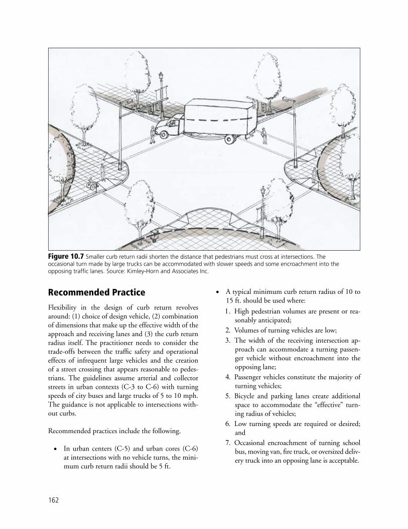
162
Recommended Practice
Flexibility in the design of curb return revolves around: (1) choice of design vehicle, (2) combination of dimensions that make up the effective width of the approach and receiving lanes and (3) the curb return radius itself. The practitioner needs to consider the trade-offs between the traffi c safety and operational effects of infrequent large vehicles and the creation of a street crossing that appears reasonable to pedes-trians. The guidelines assume arterial and collector streets in urban contexts (C-3 to C-6) with turning speeds of city buses and large trucks of 5 to 10 mph. The guidance is not applicable to intersections with-out curbs.
Recommended practices include the following.
• In urban centers (C-5) and urban cores (C-6) at intersections with no vehicle turns, the mini-mum curb return radii should be 5 ft.
• A typical minimum curb return radius of 10 to 15 ft. should be used where:
1. High pedestrian volumes are present or rea-sonably anticipated;
2. Volumes of turning vehicles are low;3. The width of the receiving intersection ap-
proach can accommodate a turning passen-ger vehicle without encroachment into the opposing lane;
4. Passenger vehicles constitute the majority of turning vehicles;
5. Bicycle and parking lanes create additional space to accommodate the “effective” turn-ing radius of vehicles;
6. Low turning speeds are required or desired; and
7. Occasional encroachment of turning school bus, moving van, fi re truck, or oversized deliv-ery truck into an opposing lane is acceptable.
Figure 10.7 Smaller curb return radii shorten the distance that pedestrians must cross at intersections. The occasional turn made by large trucks can be accommodated with slower speeds and some encroachment into the opposing traffi c lanes. Source: Kimley-Horn and Associates Inc.

163
• Curb radii will need to be larger where:
1. Occasional encroachment of a turning bus, school bus, moving van, fi re truck, or over-sized delivery truck into the opposing lane is not acceptable;
2. Curb extensions are proposed or might be added in the future; and
3. Receiving thoroughfare does not have park-ing or bicycle lanes and the receiving lane is less than 12 ft. in width.
Recommendations for Curb Radii on Transit and Freight RoutesTrucks routes should be designated on a minimum number of appropriately selected streets to reduce the impact of large turning radii on pedestrian routes. Where designated local or regional truck routes con-
fl ict with high pedestrian volumes or activities, ana-lyze freight movement needs and consider re-designa-tion of local and regional truck routes to minimize such confl icts.
On bus and truck routes, the following guidelines should be considered.
• Curb return radii design should be based on the effective turning radius of the prevailing design vehicle.
• Where the potential for confl icts with pedestri-ans is high and large vehicle turning movements necessitate curb radii exceeding 50 ft., evaluate installation of a channelized right-turn lane with a pedestrian refuge island (see the section on pe-destrian refuge islands in Chapter 9 and the sec-tion on channelized right-turn lanes in Chapter 10). To better accommodate the path of large
Figure 10.8 The existence of parking and bicycle lanes creates an “effective” turning radius that is greater than the curb return radius. Source: Community, Design + Architecture, adapted from the Oregon Bicycle and Pedestrian Plan.

164
vehicles use a three-centered compound curve in the design of the island (see the AASHTO Green Book’s Chapter 9 for design guidance).
• Where frequent turning of large vehicles takes place, avoid inadequate curb return radii as it could potentially cause large vehicles to regular-ly travel across the curb and into the pedestrian waiting area of the roadside.
Justifi cation
Intersections designed for the largest turning vehicle traveling at signifi cant speeds with no encroachment results in long pedestrian crossings and potentially high-confl ict areas for pedestrians and bicyclists. Ra-dii designed to accommodate the occasional large ve-hicle will allow passenger cars to turn at high speeds. In CSS, the selection of curb returns ranging from 5 to 25 ft. in radius is preferable to shorten pedestrian crossings and slow vehicle turning speeds to increase safety for all users.
Channelized Right-Turns
Background and Purpose
In urban contexts, high-speed channel-ized right turns are often inappropriate because they create confl icts with pedes-trians. Under some circumstances, providing chan-nelized right-turn lanes on one or more approaches at a signalized intersection can be benefi cial, but un-less designed correctly, these right-turn lanes can be undesirable for pedestrians. According to the Oregon Bicycle and Pedestrian Plan a well-designed chan-nelization island can:
• Allow pedestrians to cross fewer lanes at a time and judge confl icts separately;
• Provide refuge for slower pedestrians;
• Improve accessibility to pedestrian push-but-tons; and
• Reduce total crossing distance, which provides signal-timing benefi ts.
Right-turning drivers may not have to stop for the traffi c signal when a poorly designed channelized right-turn lane is provided. Even where pedestrian signal heads are provided at the intersection, pedes-trians are usually expected to cross-channelized right-turn lanes without the assistance of a traffi c signal. Most channelized right-turn lanes consist of only one lane and the crossing distance tends to be relatively short. However, drivers are usually looking to their left to merge into cross-street traffi c and are not al-ways attentive to the presence of pedestrians.
General Principles and Considerations
The general principles and considerations regarding channelized right turns include the following.
• Avoid using channelized right-turn lanes where pedestrian activity is signifi cant. If a channelized right-turn lane is unavoidable, use design tech-niques described to lessen the impact on pedes-trians.
• Exclusive right-turn lanes should be limited. A right-turning volume threshold of 200–300 vehicles per hour is an acceptable range for the provision of right-turn lanes. Once determined that a right-turn lane is necessary, a well-designed channelization island can help slow down traf-fi c and separate confl icts between right-turning vehicles and pedestrians (Figure 10.9).
• If an urban channelized right-turn lane is justi-fi ed, design it for low speeds (5 to 10 mph) and high-pedestrian visibility.
• For signalized intersections with signifi cant pe-destrian activity, it is highly desirable to have pe-destrians cross fully under signal control. This minimizes vehicle-pedestrian confl icts and adds to the comfort of pedestrians walking in the area.
• Consider channelized right-turn lanes at multi-lane all-way stop controlled intersections to pro-vide pedestrians an additional refuge among the complex right-of-way patterns that affect traffi c movements.
Related Thoroughfare Design Elements: Curb return radii
Crosswalks
Bicycle lanes at intersections

165
Recommended Practice
Recommended practices regarding channelized right-turn lanes include the following.
• The provision of a channelized right-turn lane is appropriate only on signalized approaches where right-turning volumes are high or large vehicles frequently turn and confl icting pedes-trian volumes are low.
• Where channelized right-turn lanes already exist at a high pedestrian activity signalized intersec-tion, pedestrians can best be served by installing pedestrian signals to the right-turn lane cross-ing. This enables the pedestrian to cross the legs of the intersection fully under signalized con-trol.
• Removing channelized right-turn lanes also makes it possible to use signing, such as NO TURN ON RED or turn prohibition signs, or exclusive pedestrian signal phases to further as-sist pedestrians in safely crossing the street.
• When channelized right-turn lanes are justifi ed for traffi c capacity or large vehicle purposes, the following practices should be used:
• Provide a low-angle right turn (about 112 degrees). This angle slows down the speed of right-turning vehicles and improves driver
visibility of pedestrians within and approach-ing the crosswalk (Figure 10.10).
• Place crosswalks so that a motorist has a clear view of pedestrians.
• A well-illuminated crossing point should be placed where drivers and pedestrians have good sight distance and can see each other in advance of the crossing point. Unless no other choices are available, the crossing point should not be placed at the point where right-turning drivers must yield to other ve-hicles and therefore might not be watching for pedestrians.
• Provide accessible islands. The island that forms the channelized right-turn lane must be a raised island of suffi cient size (at least 150 sq. ft.) for pedestrians to safely wait in a position where they are at least 4 ft. from the face of curb in all directions. A painted island is not satisfactory for pedestrians. The island also has to be large enough to accommodate accessible features, such as curb ramps (usu-ally in three separate directions) or channels cut through the raised island that are fl ush with the surrounding pavement.
• Unless the turning radii of large vehicles, such as tractor-trailers or buses, must be ac-
Figure 10.9 A channelized right turn lane typically provides a pedestrian refuge island and an uncontrolled crosswalk. Source: Dan Burden, Walkable Communities Inc.

166
commodated, the pavement in the channel-ized right-turn lane should be no wider than 16 ft. For any width right-turn lane, mark edge lines and cross-hatching to restrict the painted width of the travel way of the channelized right-turn lane to 12 ft. to slow smaller vehicles.
• If vehicle-pedestrian confl icts are a signifi cant problem in the channelized right-turn lane, it might be appropriate to provide signing to remind drivers of their legal obligation to yield to pedestrians crossing the lane in the marked crosswalk. Regulatory signs such as the TURNING TRAFFIC MUST YIELD TO PEDESTRIANS (R10-15) sign or warning signs such as the Pedestrian Cross-ing (W11-2) sign could be placed in advance of or at the crossing location.
• Signalize the channelized right-turn move-ment to eliminate signifi cant vehicle-pedes-trian confl icts. Signalization may be provided when there is/are: (1) multiple right-turning lanes, (2) something inherently unsafe about the unsignalized crossing, such as poor sight
distance or an extremely high volume of high-speed right-turning traffi c, or (3) a high pe-destrian-vehicle crash experiences.
Modern Roundabouts
Background and Purpose
Modern roundabouts are an alternative form of intersection con-trol that is becoming more widely accepted in the United States. In the appropriate circumstances, signif-icant benefi ts can be realized by converting stop-controlled and signalized intersections into modern roundabouts. These benefi ts include improved safety, speed reduction, aesthetics and operational functionality and capacity.
Figure 10.10 The preferred design of a channelized right-turn lane uses an approach angle that results in a lower speed and improved visibility. Source: Kimley-Horn and Associates Inc., adapted from an illustration by Dan Burden.
Related Thoroughfare Design Elements General intersection
layout
Pedestrian refuge islands
Pedestrian treatments at intersections
Bicycle treatments at intersection

167
Studies conducted in the United States and published by the Federal Highway Administration in Round-abouts: An Informational Guide (2000) indicate that modern single-lane roundabouts in urban ar-eas can result in up to a 61 percent reduction in all crashes and a 77 percent reduction in injury crashes when compared with stop-controlled intersections. When signalized intersections are replaced by mod-ern single-lane roundabouts in urban areas, they have resulted in up to a 32 percent reduction in all crashes and up to a 68 percent reduction in injury crashes.
General Principles and Considerations
General principles and considerations for the design of modern roundabouts include the following.
• The purpose of a modern roundabout is to pro-vide vehicles with free-fl ow capability through an intersection, while enhancing pedestrian and bicycle safety with reduced traffi c speeds.
• Roundabouts are not always the appropriate so-lution. The application of roundabouts requires close attention to a number of issues including:
• Type of design vehicle;• Use by disabled and visually impaired per-
sons; and• Effects on pedestrian route directness.
• A modern roundabout should be designed to reduce the relative speeds between confl icting traffi c streams and the absolute speed of vehicles to improve pedestrian safety. The curved path that vehicles must negotiate slows the traffi c. Vehicles entering need to be properly defl ected
Figure 10.11 A typical single lane modern roundabout design provides yield control on all approaches and defl ects approaching traffi c to slow speeds. Source: Community, Design + Architecture, adapted from an illustration in Roundabouts, An Informational Guide (FHWA 2000).

168
and yield to traffi c already in the circulating roadway of the roundabout (Figure 10.11).
• Selecting a roundabout as the appropriate traf-fi c control for an intersection requires location-specifi c analysis. Intersections with more than four legs are also good candidates for conversion to modern roundabouts, as are streets intersect-ing at acute angles.
• Locate pedestrian crossings at least 25 ft. from the roundabout entry point.
• Bicyclists can be accommodated by: (1) mixing with the fl ow of vehicular traffi c (but without pavement markings delineating a bicycle lane), or (2) use of a slip ramp from the street to the sidewalk proceeding around the intersection along separate paths, which is usually combined with pedestrian facilities. This situation can cre-ate confl icts between bicyclists and pedestrians that must be addressed through good design and signage. To accommodate different ability levels of bicyclists, both options could be imple-mented at the same roundabout unless specifi c conditions warrant otherwise.
• Single-lane roundabouts (Figure 10.12) may typically accommodate up to 20,000 entering vehicles per day, depending on a location-spe-cifi c analysis. A double-lane roundabout typi-cally accommodates up to 40,000 vehicles per day. Capacity analyses should be conducted to
determine peak hour operating conditions and levels of service. Specifi c dimensions need to ac-commodate such volumes, as are determined us-ing roundabout analysis tools. Refer to Round-abouts: An Informational Guide (FHWA 2000) for more information.
• If considering a double-lane roundabout on a boulevard, carefully evaluate pedestrian crossings. It may be desirable to provide crosswalks at mid-block locations away from the roundabout.
• Where traffi c volumes at intersections of ramps with cross streets reach volumes that would re-quire freeway grade separation reconstruction, roundabouts at such intersections might fore-stall bridge replacement.
• Intersections near active railroad grade crossings are typically not good candidates for round-abouts since traffi c would be blocked in all di-rections when trains are present.
• Sight distance for drivers entering the round-about should be maintained to the left so that drivers are aware of vehicles and bicycles in the circle. Visibility across the center of the circle is not necessary.
• Roundabouts provide an opportunity to visu-ally enhance the area. Appropriate landscaping is encouraged, even in the center island. How-ever, for safety, pedestrians are not permitted to walk to the center island. Thus, water features
Figure 10.12 Typical layout of a single lane modern roundabout. Source: Kimley-Horn and Associates Inc.

169
or features that might attract pedestrians to the center island should be discouraged.
• Proper signing and pavement markings should be designed for motorists, bicyclists and pedes-trians in advance of and at the location of the roundabout. Consideration should be given to the use of a “yield line” where appropriate, as per Section 3B.16 of the Manual of Uniform Traffi c Control Devices (FHWA 2003).
Recommended Practice
Table 10.1 provides guidance for the selection of modern roundabouts for various thoroughfare types and presents general design parameters. There are three general roundabout design philosophies in use in the United States. First, many older traffi c circles and rotaries are being eliminated or redesigned to modern roundabouts. Second, the Australian model of smaller diameter and slower speed roundabouts is gaining popularity in the United States, as is the third, the British model of larger diameter, multilane, higher-speed roundabouts. The designer should refer-ence the planning section of FHWA’s informational guide to aid in the decision-making process.
Justifi cation
Roundabouts exist at more than 15,000 intersections in Europe and Australia with decades of successful op-eration, research and improvements. Introduced into the United States in the 1990s, modern roundabouts are much improved over older American traffi c circles and rotaries. Signifi cant benefi ts related to crash and delay reduction are cited by researchers based on con-version of four-way stop-controlled and signal-con-trolled intersections in eight states.
Pedestrian Treatments at Intersections—Crosswalks
Background and Purpose
Crosswalks are used to assist pedestrians in crossing streets. The defi nition provided in the MUTCD of an unmarked crosswalk makes it clear that unmarked crosswalks can exist only at intersections, whereas the defi nition of a marked crosswalk makes it clear that marked crosswalks can exist at intersections “or else-where.”
Parameter
Urban
Compact Roundabout
Urban Single-Lane Roundabout
Minimum
“Mini-Roundabout”
Urban Double-Lane Roundabout
Maximum entry speed (mph) 15 15 20 25
Design vehicle Bus and single-unit truck drive
over apron
Bus and single-unit truck
WB-50 WB-67 with lane encroachment on
truck apron
Inscribed circle diameter (ft.) 45 To 80 80 To 100 100 To 130 150 To 180
Maximum number of entering lanes 1 1 1 2
Typical capacity (vehicles per day entering from all approaches)
10,000 15,000 20,000 40,000
Applicability by thoroughfare type:
Boulevard Not applicable Not applicable Not applicable Applicable
Arterial avenue Not applicable Not applicable Applicable Applicable
Collector avenue Applicable Not applicable Applicable Not applicable
Street Applicable Applicable Applicable Not applicable
Table 10.1 Recommended Practice for Modern Roundabouts

170
If sidewalks exist on one or more quad-rants of the intersec-tion at a signalized or unsignalized intersec-tion, then crosswalks are legally present at the intersection whether they are marked or not. Even if sidewalks do not exist at the intersection, in some states crosswalks may be legally present.
Even if unmarked crosswalks legally exist at a sig-nalized intersection, it is almost always benefi cial to provide marked crosswalks from the perspective of pedestrian safety. Marked crosswalks alert drivers ap-proaching and traveling through the intersection of the potential presence of pedestrians. Marked cross-walks also restrict pedestrian movements to only cer-tain crossing points.
If an unmarked crosswalk legally exists across a stop-controlled approach to an intersection, it is usually not necessary to mark the crosswalk. However, if en-gineering judgment determines that pedestrian safety or the minimization of vehicle-pedestrian confl icts is especially important, then providing a marked cross-walk would be appropriate.
General Principles and Considerations
The following principles and considerations should help guide the planning or design of pedestrian crossings.
• Assume that pedestrians want and need safe access to all destinations that are accessible to motorists. Additionally, pedestrians will want to have access to destinations not accessible to motorists.
• Typical pedestrian generators and destinations include residential neighborhoods, schools, parks, shopping areas and employment centers. Most transit stops require that pedestrians be able to cross the street.
• Pedestrians need safe access at many uncon-trolled locations, including intersections and mid-block locations.
• Pedestrians must be able to cross streets and highways at regular intervals. Unlike motor vehicles, pedestrians cannot be expected to go more than 300 to 400 ft. out of their way to take advantage of a controlled intersection.
• Intersections provide the best locations to control motorized traffi c to permit pedestrian crossings.
• In order to effectively indicate to motorists that they are in, or approaching, a pedestrian area and that they should expect to encounter pedestrians cross-ing the street, the design of the crosswalk must be easily understood, clearly visible and incorporate realistic crossing opportunities for pedestrians.
• There are three primary marking options: transverse, longitudinal (ladder) and diagonal (zebra) lines (Fig-ure 10.13). The placement of lines for longitudinal markings should avoid normal wheel paths and line spacing should not exceed 2.5 times the line width.
• At unsignalized or uncontrolled crossings, special emphasis longitudinal or diagonal markings should be used to increase visibility. High-contrast mark-ings also aid people with vision impairments, but no MUTCD provisions for the use of high-contrast pavement markings has yet been developed.
• Although it is not a traffi c control device, col-ored and textured crosswalk design treatments are sometimes used between transverse lines to further delineate the crosswalk, provide tactile feedback to drivers and improve aesthetics (Figure 10.14). Care should be taken to ensure that the material
Related Thoroughfare Design Elements Minimizing pedes-
trian and vehicle confl icts
Mid-block crossings
Intersection layout
Manual of Uniform Traffic Control Devices (MUTCD) Defi nition of “Crosswalk”
Unmarked Crosswalk — that part of a roadway at an intersection included within the connections of the lateral lines of the sidewalks on opposite sides of the highway measured from the curbs or in the absence of curbs, from the edges of the travers-able roadway, and in the absence of a sidewalk on one side of the roadway, the part of a roadway included within the extension of the lateral lines of the sidewalk at right angles to the centerline.
Marked Crosswalk - any portion of a roadway at an intersection or elsewhere distinctly indicated as a pedestrian crossing by lines on the surface, which may be supplemented by contrasting pavement texture, style, or color.

171
Figure 10.13 The three primary types of crosswalk markings (from left to right) are transverse, longitudinal and diagonal. Source: Kimley-Horn and Associates Inc.
used in these crosswalks is smooth, non-slip and visible. Avoid using a paver system that may shift and/or settle or that induces a high degree of vi-bration in wheelchair caster or drive wheels.
Recommended Practice
The following practice is recommended:• Provide marked crosswalks at urban signalized
intersections for all legs of the intersection; and
• Provide a marked crosswalk across an approach controlled by a STOP sign where engineering
judgment determines there is signifi cant pedes-trian activity and pedestrian safety or the mini-mization of vehicle-pedestrian confl icts is espe-cially important at that particular location.
Justifi cation
Marked crosswalks are one tool to get pedestrians safely across the street and they should be used in combination with other treatments (such as curb extensions, pe-destrian refuge islands, proper lighting, etc.). In most cases, marked crosswalks alone (with-out other treatments) should not be installed within an uncon-trolled environment when speeds are great-er than 40 mph according to AASHTO’s Guide for the Planning, Design and Operation of Pedestrian Fa-cilities (2004b) and FHWA’s Safety Effects of Marked vs. Unmarked Crosswalks at Uncontrolled Locations (2002).
Figure 10.14 Crosswalks with colored bricks contrast with concrete pavement. Painted stripes marking the brick crosswalks increase visibility. Source: Kimley-Horn and Associates Inc.
Related Thoroughfare Design Elements Curb return radii
Channelized right turns
Lane width
Crosswalks
Mid-block crossings
Bus stops

172
Pedestrians can legally cross the street at any inter-section whether a marked crosswalk exists or not. To enhance awareness by motorists, install crosswalks on all approaches of signalized intersections. If special circumstances make it unsafe to do so, attempt to mitigate the circumstance.
Curb Extensions
Background and Purpose
Curb extensions (also called nubs, bulb-outs, knuck-les, or neck-downs) extend the line of the curb into the traveled way reducing the width of the street. Curb extensions typically occur at intersections, but can be used at mid-block locations to shadow the width of a parking lane, bus stop, or loading zone. Curb exten-sions can provide the following benefi ts:
• Reduce pedestrian crossing distance and expo-sure to traffi c;
• Improve driver and pedestrian sight distance and visibility at intersections;
• Separate parking maneuvers from vehicles turn-ing at the intersections;
• Visually and physically narrow the traveled way, resulting in a calming effect;
• Encourage and facilitate pedestrian crossing at preferred locations;
• Keep vehicles from parking too close to inter-sections and blocking crosswalks;
• Provide wider waiting areas at crosswalks and intersection bus stops;
• Reduce the effective curb return radius and slow turning traffi c;
• Enhance ADA requirements by providing space for level landings; and
• Provide space for streetscape elements if extend-ed beyond crosswalks.
Curb extensions serve to better defi ne and delineate the traveled way as being separate from the parking lane and roadside. They are used only where there is on-street parking and the distance between curbs is greater than what is needed for the vehicular traveled way.
General Principles and Considerations
General principles and considerations regarding curb extensions include the following.
• Curb extensions may be used at intersections in any context zone, but are emphasized in urban centers (C-5), urban cores (C-6) and other loca-tions with high levels of pedestrian activity.
• Curb extensions help manage confl ict between modes, particularly between vehicles and pedes-trians. The curb extension is an effective mea-sure to improve pedestrian safety and comfort and might contribute to slower vehicle speed.
• The design of the curb extension should cre-ate an additional pedestrian area in the driver’s fi eld of vision, thereby increasing the visibility of pedestrians as they wait to cross the street, as shown in Figure 10.15.
• Curb extensions are used only where there is on-street parking and only a small percentage of turning vehicles that are larger than the design vehicle.
• Curb extensions are not applicable to roadways without on-street parking lanes, intersections
Figure 10.15 Curb extensions can improve pedestrian visibility and reduce crossing distance. Source: Community, Design + Architecture.

173
with exclusive right-turn lanes adjacent to the curb, or intersections with a high volume of right-turning trucks or buses turning into nar-row cross streets.
• Carefully consider drainage in the design of curb extensions to avoid interrupting the fl ow of water along the curb, thus pooling water at the crosswalk.
• Curb extensions work especially well with di-agonal parking, shadowing the larger profi le of
the row of parking and providing large areas in the pedestrian realm.
• Adjusting the curb return radius can accommo-date emergency vehicle and large design vehi-cles. An “effective” radius can accommodate the design vehicle through the use of a mountable (or fl ush with pavement) extension with bol-lards to protect the pedestrian area as shown in Figures 10.16 and 10.17. Flush curb extensions are frequently combined with raised intersec-
Figure 10.16 A mid-block crossing with a fl ush curb in Australia. Pedestrians are separated from passing vehicles with bollards. Source: Community, Design + Architecture.
Figure 10.17 Use of contrasting material and bollards to delineate the pedestrian and vehicle areas. Source: Kimley-Horn and Associates Inc.

174
tions. However, care should be taken to provide adequate vehicle turning paths outside the des-ignated pedestrian waiting area.
• Where bicycle lanes exist, the curb extension must be outside the width of the bicycle lane.
• Design curb extension radii to allow street clean-ing vehicles to reach and turn all inside and out-side corners. Normally this requires a radius of 15 ft. This will also help stormwater fl ow in the gutters around corners.
Recommended Practice
The following practices are recommended when de-signing curb extensions on major urban thorough-fares:
• Reduce crossing width at intersections by ex-tending the curb line into the street by 6 or 7 ft. for parallel parking and to within 1 ft. of stall depth with angled parking. Ensure that the curb extension does not extend into travel or bicycle lanes.
• Apply the appropriate curb return radius in the design of a curb extension. If necessary, use three-centered or asymmetric curb returns to accommodate design vehicles.
• Where buses stop in the travel lane, curb ex-tensions can be used to defi ne the location of the stop and create additional waiting area and space for shelters, benches and other pedestrian facilities.
• When possible, allow water to drain away from the curb extension. In other cases a drainage in-let may need to be installed and connected to an existing underground stormdrain system.
• Curb extensions are usually constructed integral with the curb. In retrofi t projects, curb exten-sions may be constructed away from the curb to allow drainage along the original fl owline (Fig-ure 10.18). Consider that this design might re-quire additional maintenance to keep the fl ow-line clear.
• When considering construction of curb exten-sions where an existing high road crown exists, reconstruction of the street might be necessary to avoid back draining the sidewalk toward abutting buildings. Slot drains along the side-walk may provide an alternate solution.
• Sidewalks, ramps, curb extensions and cross-walks should all align with no unnecessary me-andering.
Justifi cation
Curb extensions in unused or underutilized street space can be used to shorten pedestrian crossing dis-tance, increase pedestrian visibility and provide ad-ditional space for pedestrian queuing and support activity. Extensions can increase safety, effi ciency and attractiveness.
Figure 10.18 Curb extensions may be used as landscaping or hardscape opportunities. This example shows a retrofi t curb extension with drainage retained between the extension and the curb. Source: Community, Design + Architecture.

175
Bicycle Lane Treatment at Intersections
Background and Purpose
Selecting appropri-ate bicycle lane treat-ments at intersections requires providing uniformity in facil-ity design, signs and pavement markings for bicyclists and motorist safety. The objective is to promote a clear understand-ing of safe paths through all intersection movements for bicyclists and motorists.
General Principles and Considerations
General principles and considerations regarding bi-cycle lane treatment at intersections include the fol-lowing.
• To maintain continuity and improve bicyclist safety, bicycle lanes should be striped through the intersection approach and up to the stop line or crosswalk.
• Since bicyclists ride on the right-hand side of adjacent motor vehicle traffi c, bicyclists desiring to travel straight through an intersection con-fl ict with motor vehicles that are making a right turn at the intersection. On intersection ap-proaches that have a shared through/right-turn lane, the only choice is to have bicyclists and right-turning motor vehicles yield to each other at the intersection.
• On intersection approaches that have an ex-clusive right-turn lane, the bicycle lane should be positioned to the left of the right-turn lane. Drivers of right-turning motor vehicles moving into the turn lane have an obligation to yield to any present bicyclists. The higher-speed motor vehicle is usually approaching the beginning of the turn lane from behind the bicyclist and has a better view of the potential confl ict.
Related Thoroughfare Design Elements Bicycle facilities
Curb extensions
Right-turn channelization
Lane width
• A more complex situation exists when an ex-clusive right-turn lane is created by dropping a through lane. The bike lane can typically transi-tion from the right of the right-turn lane to the left of the right-turn lane with a shift in align-ment.
• Where there are numerous left-turning bicy-clists, a left-turn bicycle lane may be provided on an intersection approach. This lane is located between the vehicular left-turn lane and the ad-jacent through lane so that bicyclists can keep to the outside as they turn left.
• On approaches to roundabout intersections, the bicycle lane needs to be terminated just prior to entering the roundabout and should not be provided on the circular roadway of the round-about intersection.
Recommended Practice
The recommended practice for bicycle lane treat-ment at intersections on major urban thoroughfares is shown in Table 10.2.
Justifi cation
At intersections, bicyclists proceeding straight through and motorists turning right must cross paths. Striping and signing confi gurations that encourage crossings in advance of the intersection in a weaving fashion reduce confl icts at the intersection and improve bicy-cle and motor vehicle safety. Similarly, modifi cations such as special sight distance considerations, wider roadways to accommodate on-street lanes, special lane markings to channelize and separate bicycles from right-turning vehicles, provisions for left-turn bicycle movements and special traffi c signal designs (such as conveniently located push-buttons at actuated signals or even separate signal indications for bicyclists) also improve safety and operations and balance the needs of both transportation modes when on-street bicycle lanes or off-street bicycle paths enter an intersection.

176
Bus Stops at Intersections
Background and Purpose
CSS for bus stops at intersections empha-sizes an improved en-vironment for pedes-trians and techniques for effi cient transit operations. Design considerations for buses are addressed in detail in the section on mid-block bus stops in Chapter 9.
Recommended Practice
Placement of Bus Stops at IntersectionsThe preferred location for bus stops is the nearside or far side of an intersection. This location provides the best pedestrian accessibility from both sides of the street and connection to intersecting bus routes. While not preferred, bus stops may also be placed at a mid-block location on long blocks or serve a major transit generator (See Chapter 9). Guidance and considerations related to bus stops at intersections include the following.
• Consider a nearside stop on two lane thorough-fares where vehicles will not pass a stopped bus.
• Consider a far-side stop on thoroughfares with multiple lanes where vehicular traffi c may pass uncontrolled around the bus.
With pedestrian crosswalks• Bike lane striping should not be installed across any pedestrian crosswalks, and, in most cases, should not continue
through any street intersections.With no pedestrian crosswalks• Bike lane striping should stop a the intersection stop line, or the near side cross street right of way line projection, and
then resume at the far side right-of-way line projection.• Bike lane striping may be extended through complex intersections with the use of dotted or skip lines.Parking considerations• The same bike lane striping criteria apply whether parking is permitted or prohibited in the vicinity of the intersection.Bus stop on near side of intersection or high right-turn volume at unsignalized minor intersections with no stop controls• 6-in. solid line should be replaced with a broken line with 2-ft. dashes and 6-ft. spaces for the length of the bus stop.
Bike lane striping should resume at the outside line of the crosswalk on the far side of the intersection.Bus stop located on far side of the intersection• Solid white line should be replaced with a broken line for a distance of at least 80 ft. from the crosswalk on the far side
of the intersection.T-intersections with no painted crosswalks• Bike lane striping on the far side across from the T-intersection should continue through the intersection area with
no break. If there are painted crosswalks, bike lane striping on the side across from the T-intersection should be discontinued at the crosswalks.
Pavement markings• Bike lane markings should be installed according to the provisions of Chapter 9C of the MUTCD. • The standard pavement symbols are one of two bicycle symbols (or the words “BIKE LANE”) and a directional arrow as
specifi ed in the MUTCD. Symbols should be painted on the far side of each intersection. Pavement markings should be white and refl ectorized.
Signs• Bike lanes should be accompanied by appropriate signing at intersections to warn of confl icts (see Chapter 9B of the
MUTCD).
Table 10.2 Recommended Practice for Bicycle Lane Treatment at Intersections on Major Urban Thoroughfares
Related Thoroughfare Design Lane width
Curb extensions
Mid-block bus stops
Curb return radius
Crosswalks

177
• On thoroughfares where vehicular traffi c is con-trolled by a signal, the bus stop may be located either nearside or far side.
• Where it is not desirable to stop the bus in a travel lane and a bus pullout is warranted, a far-side or mid-block stop is generally preferred. As with other elements of the roadway, consistency of stop placement lessens the potential for op-erator and passenger confusion.
• When locating a bus stop in the vicinity of a driveway, consider issues related to sight distance, blocking access to development and potential confl icts between automobiles and buses.
The placement of bus stops at intersections vary from site to site. However general considerations for the placement of bus stops at intersections include the following.
• When the route alignment requires a left turn, the preferred location for the bus stop is on the far side of the intersection after the left turn is completed.
• When the route alignment requires a left turn and it is infeasible or undesirable to locate a bus stop far side of the intersection after the left turn, a mid-block location is preferred. A mid-block bus stop should be located far enough upstream from the intersection so a bus can maneuver into the proper lane to turn left.
• If there is a high volume of right turns at an in-tersection or when the transit route turns right at an intersection, the preferred location for a stop is on the far side of the intersection.
• In circumstances where the accumulation of buses at a far-side stop would spill over into the intersection and additional length is not avail-able, the stop should be placed on the nearside of the intersection.
• At complex intersections with dual right- or left-turn lanes, far-side stops are preferred be-cause they remove the buses from the area of complicated traffi c movements.
• When there is substantial transfer activity be-tween two bus routes on opposite sides of the street, placing one stop nearside and one far side can minimize pedestrian activity within the in-tersection.
Table 10.3 summarizes the advantages and disadvantages of far-side and nearside bus stop placements.
Curb Extension Bus Stops (Bus Bulbs)A curb extension may be constructed along streets with on-street parking in urban centers (C-5) and ur-ban cores (C-6). Curb extensions may be designed in conjunction with bus stops to facilitate bus operations and passenger access. The placement of a bus stop on a curb extension should follow the same guidelines as those previously stated (a nearside stop is preferred on two-lane streets where vehicles cannot pass a stopped bus). In the case of a street with multiple lanes where vehicular traffi c may pass uncontrolled around the bus, a far side stop is preferred for sight distance issues.
A bus stop on the nearside of a single-lane approach of an uncontrolled intersection should completely obstruct the traffi c behind it. Where it is not accept-able to have stopped buses obstruct a lane of traffi c and a bus turnout is justifi ed according to the crite-ria presented in Chapter 9 (section on mid-block bus stops), a bus stop may be placed on the far side in the parking lane just beyond the curb extension. It might be appropriate to place a bus stop on a far-side curb extension at an uncontrolled intersection if the war-rants for a bus pullout are not met and its placement will not create a traffi c hazard.
Nearside curb extensions are usually about 6 ft. in width and of suffi cient length to allow passengers to use the front and back doors of a bus. A nearside curb extension bus stop is shown in Figure 10.19.
Besides reducing the pedestrian crossing distances, curb extensions with nearside bus stops can reduce the impact to parking (compared to typical bus zones), mitigate traffi c confl icts with autos for buses merging back into the traffi c stream, make crossing pedestrians more visible to drivers and create additional space for passenger amenities, such as a shelter and/or a bench.
In areas where curb extensions are desired, but it is not acceptable to have the bus stop in the travel lane, a far-side pullout area can be created in the parking lane. This location and design eliminates the safety hazard of vehicles passing the bus prior to entering the intersection.

178
Queue JumpersQueue jumpers provide priority treatment for buses along arterial streets by allowing buses to bypass traf-fi c queued at congested intersections. Queue jump-ers evolved from the need to solve problems not an-swered by bus turnouts. In the past, traffi c engineers constructed bus turnouts to move buses out of the traffi c stream while they are stopped for passengers. Bus turnouts introduce signifi cant travel time penal-ties to bus patrons because buses are delayed while at-tempting to re-enter the traffi c stream. Queue jump-ers are able to provide the double benefi t of removing stopped buses from the traffi c stream to benefi t the general traffi c and getting buses through congested intersections so as to benefi t bus operations.
Queue jumpers consist of a nearside right-turn lane and a far-side bus stop and/or acceleration lane. Buses are allowed to use the right-turn lane to bypass traf-fi c congestion and proceed through the intersection. Additional enhancements to queue jumpers could in-clude an exclusive bus-only lane upstream from the traffi c signal, extension of the right-turn lane to by-pass traffi c queued at the intersection, or advanced green indication allowing the bus to pass through the intersection before general traffi c does.
Queue Jumper with an Acceleration LaneThis option includes a nearside right-turn lane (buses excepted), nearside bus stop and acceleration lane for buses with a taper back to the general-purpose lanes. The length of the acceleration lane is based on speed and should be designed by an experienced engineer.
Source: Bus Stop Safety and Design Guidelines Manual, Orange County Transportation Authority and Kimley-Horn and Associates, Inc.
Farside Bus StopsAdvantages Disadvantages
• Minimizes confl ict between buses and right turning vehicles traveling in the same direction.
• Minimizes sight distance problems on approaches to the intersection.
• Encourages pedestrians to cross behind the bus.
• Minimizes area needed for curbside bus zone.
• If placed just beyond a signalized intersection in a bus turnout, buses may more easily re-enter the traffi c stream.
• If a turnout is provided, vehicle capacity through intersection is unaffected.
• If bus stops in travel lane, could result in traffi c queued into intersection behind the bus (turnout will allow traffi c to pass around the stopped bus).
• If bus stops in travel lane, could result in rear-end accidents as motorists fail to anticipate stopped traffi c.
• May cause passengers to access buses further from crosswalk.
• May interfere with right turn movement from cross street.
Nearside Bus StopsAdvantages Disadvantages
• Minimizes interference when traffi c is heavy on the farside of an intersection.
• Allows passengers to access buses close to crosswalk.
• Driver may use the width of the intersection to pull away from the curb.
• Allows passengers to board and alight when the bus is stopped for a red light.
• Provides the driver with the opportunity to look for oncoming traffi c, including other buses with potential passengers.
• Stopped bus may interfere with a dedicated right turn lane.
• May cause sight distance problem for cross-street traffi c and pedestrians.
• If located at a signalized intersection, and if the shoulder width at the stop is such that buses will exit the traffi c stream, a traffi c queue at a signal may make it diffi cult for buses to re-enter the traffi c stream.
• Prohibits through traffi c movement with green light, similar to farside stop without a bus turnout.
• May cause pedestrians to cross in front of the bus at intersections.
Table 10.3 Advantages and Disadvantages of Farside and Nearside Bus Stops

179
Figure 10.19 A curb extension bus stop. Source: Kimley-Horn and Associates Inc.
Queue Jumper with a Far Side Bus StopThis option may be used when there is a heavy direc-tional transfer to an intersecting transit route. Bus-es can bypass queues either using a right-turn lane (buses excepted) or an exclusive bus queue jump lane. Since the bus stop is located on the far side, a standard transition can be used for buses to re-enter the traffi c stream. Queue jumpers at major urban thoroughfare intersections should be considered when:
1. High-frequency bus routes have an average headway of 15 min. or less;
2. Forecasted traffi c volumes exceed 500 vehicles per hour in the curb lane during the peak hour and right-turn volumes exceed 250 vehicles per hour during the peak hour; and
3. Intersection operates at an unacceptable level of service (defi ned by the local jurisdiction).
Works Cited
American Association of State Highway and Trans-portation Offi cials. 2004a. A Policy on Geometric Design of Highways and Streets. Washington, DC: AASHTO.
American Association of State Highway and Trans-portation Offi cials. 2004b. Guide for the Planning, Design and Operation of Pedestrian Facilities. Washington, DC: AASHTO.
Federal Highway Administration. 2003. Manual of Uniform Traffi c Control Devices. Washington, DC: FHWA.
Federal Highway Administration. 2000. Round-abouts: An Informational Guide. Washington, DC: FHWA.
Federal Highway Administration. 2002. Safety Ef-fects of Marked vs. Unmarked Crosswalks at Un-controlled Locations. Washington, DC: FHWA.
Oregon DOT. Oregon Bicycle and Pedestrian Plan.

180
References for Further Reading
American Association of State Highway and Trans-portation Offi cials. A Guide to Achieving Flexibility in Highway Design. Washington, DC: AASHTO, May 2004.
American Association of State Highway and Trans-portation Offi cials. Guide for the Development of Bicycle Facilities. Washington, DC: AASHTO, 1999.
American Planning Association. Bicycle Facility Planning. Chicago, IL: APA, 1995.
Congress for the New Urbanism. Codifying New Urbanism. Chicago, IL: American Planning Associa-tion, May 2004.
Federal Highway Administration. Flexibility in Highway Design. Washington, DC: FHWA, 1997.
Institute of Transportation Engineers. Innovative Bi-cycle Treatments. Washington, DC: ITE, 2002.
Insurance Institute for Highway Safety/Ryerson Poly-technic University. Crash Reductions Following Installation of Roundabouts in the United States. March 2000.
Jacobs, Allan. Great Streets. Cambridge, MA: MIT Press, 1995.
Leisch, Joel P. Freeway and Interchange Geometric Design Handbook. Washington, DC: ITE, 2005.
Oregon Department of Transportation. Main Street—When a Highway Runs Through It, A Handbook for Oregon Communities. Oregon Department of Trans-portation, November 1999.
Transportation Research Board. NCHRP Report 330: Effective Utilization of Street Width on Urban Arterials. Washington, DC: TRB, 1990.
Transportation Research Board. NCHRP Report 500, Volume 3: A Guide for Addressing Collisions with Trees in Hazardous Locations. Washington, DC: TRB, 2003.

181
Purpose
This chapter identifi es resources to help practitioners achieve CSS for major thoroughfares in urban areas comprised of homogenous land uses (business park, industrial, etc.) or where vehicle mobility is a prior-ity. Stakeholder involvement continues to be an im-portant part of the planning process that establishes a vision for the corridor/thoroughfare. Although in this case, the vision is a mobility priority character that plays a major mobility/capacity role in the network, thus permitting other thoroughfares to emphasize other roles.
Objectives
This chapter:
1. Defi nes the types of land use categories appli-cable to this section of the report;
2. Compares the conventional and CSS processes for determining cross sections for vehicle mobil-ity priority roadways;
3. Identifi es the applicability of the guidelines in this report for single land use and vehicle mobil-ity priority areas; and
4. Identifi es general design parameters for thor-oughfares in single land use and vehicle mobil-ity priority areas.
Single Land Use Categories
This report addresses CSS primarily in walkable, mixed-use residential and commercial urban areas. There are many areas in urban areas that contain homogenous or single type of land use. These areas might be long corridors or large districts which, by their nature, are low intensity and low density and do not provide the mix of uses, development patterns, or roadway networks conducive to walking. Transpor-tation in single land use areas is primarily by motor
vehicles, although transit and bicycling can be viable modes. Single land use areas might contain commer-cial or industrial uses that rely on freight movement and therefore need to accommodate signifi cant num-bers of large vehicles.
The following are brief descriptions of some of the land use categories that fall under the single-use defi -nition.
• Auto-oriented commercial/employment—These areas are comprised of large, or multiple, commercial developments located within a cor-ridor or a district. They are primarily comprised of:
• Strip commercial/shopping center or mall (Figure 11.1)—Large commercial sites with surface parking lots adjacent to the thorough-fare right-of-way. Buildings are either at the back of the site away from the thoroughfare or for large centers and malls, in the middle of parcels.
• Business park/campus offi ce (see Figure 11.2)—Large parcel offi ce/business campus or park. Buildings are set well back from the thoroughfare and surrounded by large land-scaped edges and surface parking lots. Road-way pattern and block size are of a nearly unwalkable scale.
• Single-use residential not fronting on thor-oughfare (Figure 11.3)—Housing units front on side streets or back up to the thoroughfare. Developments are inwardly focused or oriented away from the thoroughfare, often presenting a high wall at the edge of the right-of-way. Resi-dences are buffered from the thoroughfare by roadside width. There are typically no signifi -cant complementary uses within walking dis-tance.
• Industrial/manufacturing (Figure 11.4)—Sim-ilar in description to business park except that developments might be single parcels, charac-terized by large, low-density buildings, equip-
C h a p t e r
Thoroughfares in Single Land Use or Vehicle Mobility Priority Areas
11

182
Figure 11.1 Large retail centers are examples of single uses. Source: Kimley-Horn and Associates Inc.
Figure 11.2 Offi ce complexes are often set back away from the thoroughfare creating an auto-oriented environment. Source: Kimley-Horn and Associates Inc.

183
Figure 11.4 Industrial areas may have roadways dominated by large vehicles. Source: Kimley-Horn and Associates Inc.
ment yards and parking. Freight vehicles might dominate roadways.
Passive park, natural reserve, or intentional buffer area—These areas are mainly open space with little human activity. These areas may also include land adjacent to access controlled right-of-way or easements (railroad, freeway, power lines).
Determining Thoroughfare Cross-Sections
Determining thoroughfare cross sections in single use areas uses a similar process to that described in Chap-ters 5 and 6 for walkable, mixed-use urban areas. This section compares the conventional process for deter-mining cross sections for single land-use areas and vehicle mobility priority thoroughfares with the CSS process.
Conventional Cross-Section Determination The conventional process for determining initial thoroughfare cross sections typically includes the fol-lowing steps:
• Identify the functional classifi cation;
• Identify the area type (rural or urban);
• Develop traffi c projections and conduct opera-tional analyses;
• Assess right-of-way availability and require-ments; and
• Design the initial cross section.
The conventional process begins with identifying the functional classifi cation and area type. Combined, the functional class and area type provide the practi-tioner with the facility’s service characteristics, types of design vehicles, design speed, etc. and often is tied to an agency’s geometric design standards. Next, the practitioner projects design year traffi c conditions and evaluates the facility’s operations and level of ser-
Figure 11.3 Residential subdivisions adjacent to major thoroughfares are often inwardly focused and separated by walls. Source: Kimley-Horn and Associates Inc.

184
vice (LOS). This step typically results in the number of lanes needed to accommodate future traffi c, meet LOS objectives or standards and identify geometric requirements, particularly at intersections. The prac-titioner assesses the available or required right-of-way to accommodate the number of lanes and other de-sign features. If right-of-way is constrained, the prac-titioner evaluates trade-offs and determines the high-est priority design elements. This step leads to the development of an initial cross section, upon which the practitioner can begin detailed designs.
The conventional process emphasizes the role of functional classifi cation and traffi c operations in the development of cross sections. In vehicle-dominated areas, this process is appropriate for accommodating traffi c, but de-emphasizes other modes of travel. Pe-destrian, bicycle and transit user needs in single land use and vehicle mobility priority areas, even though demand is less, are often addressed through the provi-sion of minimal facilities.
CSS Cross-Section Determination In contrast to the conventional process, the CSS pro-cess for determining thoroughfare cross sections in single land use and vehicle mobility priority areas is similar to any CSS thoroughfare design process. The steps are as follows:
• Determine the local objectives and priorities from stakeholder process;
• Identify the land use category;
• Assess adjacent activity and other conditions;
• Determine the functional classifi cation;
• Determine the thoroughfare type; and
• Design the initial cross section.
The CSS process begins with identifying the local vision, objectives and priorities for the area and thoroughfare. This involves working with stakeholders. The existing and future character of the area and its supporting thor-oughfares is determined by assessing land use categories and types of adjacent activities, which result in user needs. For example, the character of a single use business park may be low-intensity development set back amidst large landscaped grounds, but the buildings need to be accessible by pedestrians who arrive by transit or walk between buildings. This may lead to a series of off-street paths that connect the roadside to buildings and connect
buildings to each other. User needs can include traffi c projections and operations analysis.
Once the practitioner has identifi ed the land use, ad-jacent activities, user needs and character, the design process is similar to the process described in Chapters 3 and 5 for identifying functional classifi cation and associated thoroughfare type. This leads to the devel-opment of an initial cross section.
Applicability of Report to Vehicle Mobility Priority Thoroughfare Design
Most of the guidance presented in this report is applicable to the design of major urban thorough-fares in single land use and vehicle mobility prior-ity areas. Table 11.1 identifies the applicability of each of the chapters and sections that provide de-sign guidelines for the roadside (Chapter 8), the traveled way (Chapter 9) and intersections (Chap-ter 10). When designing a vehicle mobility pri-ority thoroughfare, the practitioner can use this table to identify the sections with relevant and ap-plicable considerations and guidance. If not iden-tified in the table, the guidance provided in local agency standards or the AASHTO A Policy for the Geometric Design of Highways and Streets, otherwise known as the Green Book (2004) is rec-ommended.
Vehicle Mobility Priority Thoroughfare Design Parameters
Table 11.2 and 11.3 present the general design pa-rameters for arterial and collector thoroughfares in single land use and vehicle mobility priority areas. The tables provide general guidance on dimensions and criteria for common elements of the cross sec-tion and other vital design elements of major urban thoroughfares. Table 11.2 presents guidance for arte-rial thoroughfares (boulevards and avenues) and Table 11.3 presents guidance for collector thoroughfares (avenues and streets).
The guidance in these tables does not necessar-ily refl ect the recommended dimensions and/or practices of each of the design criteria presented

185
Chapter/Section Applicable for CSS?Chapter 8 – Roadside
Principles and considerations YesEdge zones YesFurnishing zones Yes Street furniture No Landscaping Yes Pedestrian buffers Yes
Pedestrian throughway zones Yes
Frontage zones NoDriveway crossings Yes
Chapter 9 – Travelway
Functions/actions to be accommodated YesAccess management YesEmergency vehicle operations YesTransition principles YesMedians YesBicycle facilities YesOn-street parking Only where permittedTransition design YesMid-block crosswalks YesPedestrian refuge islands YesMid-block bus stops YesSnow removal considerations Yes
Chapter 10 – Intersections
Intersection geometry YesCurb return radii NoChannelized right turns NoRoundabouts YesPedestrian treatments Yes
Curb extensionsWhere curb parking is to be
provided full timeBike lane treatments YesBus stops Yes
Table 11.1 Applicability of Report Sections to Vehicle Mobility Priority Major Urban Thoroughfares
in Chapters 8 through 10 for walkable mixed-use urban areas. Tables 11.2 and 11.3 refl ect the more conventional practice and design criteria for auto-oriented roadway design. The primary source of these criteria is A Policy on Geometric Design of Streets and Highways, American Association of State Highways and Transportation Offi cials, Washington, DC.
Works Cited
American Association of State Highway and Trans-portation Offi cials. A Policy on the Geometric De-sign of Highways and Streets. Washington, DC: AASHTO, 2004.

Des
ign
Char
acte
rist
ics
Para
met
erSt
rip
Com
mer
cial
/Sho
ppin
g Ce
nter
Busi
ness
Par
k/In
dust
rial
Sing
le-U
se R
esid
enti
al N
ot
Fron
ting
On
Thor
ough
fare
Pass
ive
Park
, Nat
ure
Pres
erve
, In
tent
iona
l Buf
fer
Are
aCa
mpu
s O
ffi c
eTr
avel
ed W
ayTy
pica
l ADT
20,0
00+
<25
,000
20,0
00+
<25
,000
25,0
00+
<25
,000
20,0
00+
<20
,000
10,0
00+
<10
,000
Thor
ough
fare
type
Boul
evar
dAv
enue
Boul
evar
dAv
enue
Boul
evar
dAv
enue
Boul
evar
dAv
enue
Boul
evar
dAv
enue
Off-
stre
et p
arki
ng a
cces
sLi
mite
d fro
m
thor
ough
fare
; sid
e st
reet
Lim
ited
from
th
orou
ghfa
re; s
ide
stre
et
Lim
ited
from
thor
-ou
ghfa
re; s
ide
stre
et
Lim
ited
from
th
orou
ghfa
re; s
ide
stre
et
Lim
ited
from
thor
-ou
ghfa
re; s
ide
stre
et
Lim
ited
from
th
orou
ghfa
re; s
ide
stre
et
From
sid
e st
reet
on
ly
Lim
ited
from
th
orou
ghfa
re; s
ide
stre
et
From
sid
e st
reet
on
ly
Lim
ited
from
th
orou
ghfa
re; s
ide
stre
etO
pera
ting
spee
d (m
ph)
35 to
40
3545
35 to
40
4535
to 4
035
to 4
030
to 3
545
40(d
esig
n sp
eed
= 5
mph
hi
gher
)
Num
ber o
f thr
ough
lane
s
4 to
6 ty
pica
l; 6
to
8 w
here
par
alle
l ca
pacit
y no
t ava
il-ab
le
2 to
44
to 6
typi
cal;
6 to
8
whe
re p
aral
lel c
apac
-ity
not
ava
ilabl
e2
to 4
4 to
6 ty
pica
l; 6
to 8
w
here
par
alle
l cap
ac-
ity n
ot a
vaila
ble
2 to
4
4 to
6 ty
pica
l; 6
to
8 w
here
par
alle
l ca
pacit
y no
t ava
il-ab
le
2 to
4
4 to
6 ty
pica
l; 6
to
8 w
here
par
alle
l ca
pacit
y no
t ava
il-ab
le
2 to
4
Lane
wid
th11
to 1
2 ft.
11 to
12
ft.11
to 1
2 ft.
11 to
12
ft.12
ft.+
12 ft
.+11
to 1
2 ft.
11 to
12
ft.11
to 1
2 ft.
11 to
12
ft.
On-
stre
et p
arki
ng
Depe
nds
on n
eed
Depe
nds
on n
eed
Non
eN
one
Non
eN
one
Non
eN
one
Non
eN
one
Med
ian
[1]
16 to
18
ft.O
ptio
nal
16 to
18
ft.O
ptio
nal
16 to
22
ft.N
one
16 to
18
ft.O
ptio
nal
16 to
18
ft.O
ptio
nal
14 to
18
ft.14
to 1
8 ft.
14 to
18
ft.14
to 1
8 ft.
Acce
ss m
anag
emen
t [2]
High
Mod
erat
eM
oder
ate
Low
Mod
erat
eLo
wHi
ghLo
wM
oder
ate
Mod
erat
e
Bike
Lan
es6
ft. b
ike
lane
whe
n ne
eded
for b
icycle
net
wor
k co
nnec
tivity
; Opt
iona
l 6 ft
. lan
e w
here
ther
e ar
e ne
arby
par
alle
l fac
ilitie
sRo
adsid
e
Min
imum
/des
irabl
e ro
adsid
e w
idth
(inc
l. 1
ft. c
lear
ance
be
hind
sid
ewal
k)6
ft./1
4 ft.
6 ft.
/14
ft.6
ft./1
4 ft.
6 ft.
/14
ft.6
ft./1
4 ft.
6 ft.
/14
ft.6
ft./1
2 ft.
6 ft.
/12
ft.6
ft./1
4 ft.
6 ft.
/14
ft.
Pede
stria
n bu
ffers
/pla
ntin
g st
rip w
idth
0 to
8 ft
.0
to 8
ft.
0 to
8 ft
.0
to 8
ft.
0 to
8 ft
.0
to 8
ft.
0 to
6 ft
. [3]
0 to
6 ft
. [3]
0 to
8 ft
.0
to 8
ft.
Min
. sid
ewal
k w
idth
5 ft.
5 ft.
5 ft.
5 ft.
5 ft.
5 ft.
5 ft.
5 ft.
5 ft.
5 ft.
Stre
et li
ghtin
gSa
fety
ligh
ting
reco
mm
ende
d th
roug
hout
seg
men
t and
at i
nter
sect
ions
Inte
rsec
tions
Traf
fi c s
igna
l con
trol
Prio
ritize
sig
nal p
rogr
essio
n, tr
affi c
mov
emen
t effi
cienc
y, tra
nsit
rout
es; s
afel
y ac
com
mod
ate
pede
stria
n cr
ossin
gs w
ith m
ulti-
stag
e cr
ossin
gs if
nec
essa
ry w
here
med
ians
are
pro
vide
d w
ith a
dequ
ate
pede
stria
n re
fuge
w
idth
(min
. 8 ft
.).
Curb
radi
i
30 ft
. to
50 ft
. or 3
-cen
ter c
urve
s; la
rger
with
hea
vy ri
ght t
urns
or t
ruck
vol
umes
and
cor
ner i
sland
s30
ft.
30 ft
.
30-5
0 ft.
or 3
-cen
ter c
urve
s; la
rger
with
he
avy
right
-turn
s or
truc
k vo
lum
es a
nd
corn
er is
land
s
Roun
dabo
uts
Opt
iona
l at l
ow a
nd m
ediu
m v
olum
e in
ters
ectio
ns w
here
suf
fi cie
nt ro
unda
bout
cap
acity
can
be
deve
lope
d.N
otes
:
[1] D
imen
sions
sho
wn
in ta
ble
are
for s
ingl
e le
ft-tu
rn la
nes.
Maj
or in
ters
ectio
ns m
ay b
e siz
ed to
acc
omm
odat
e do
uble
left-
turn
lane
s.
[2] A
cces
s m
anag
emen
t inv
olve
s pr
ovid
ing
(in o
ther
wor
ds, m
anag
ing)
acc
ess
to la
nd d
evel
opm
ent i
n a
way
that
pre
serv
es s
afet
y an
d re
ason
able
traf
fi c fl
ow o
n pu
blic
stre
ets.
See
Chap
ter 9
Trav
eled
Way
Des
ign
Gui
delin
es (a
cces
s m
anag
emen
t sec
tion)
for m
ore
info
rma-
tion.
Low
, mod
erat
e, a
nd h
igh
desig
natio
ns re
late
d to
the
leve
l of a
cces
s re
stric
tions
. A h
igh
leve
l of a
cces
s m
anag
emen
t use
s m
edia
ns to
rest
rict m
idbl
ock
turn
s, co
nsol
idat
es d
rivew
ays
and
cont
rols
the
spac
ing
of in
ters
ectio
ns. A
low
leve
l of a
cces
s m
anag
emen
t lim
its fu
ll ac
cess
at s
ome
inte
rsec
tions
.
[3] I
f tru
cks
are
allo
wed
to p
ark
on th
e st
reet
, the
pla
ntin
g st
rip s
houl
d no
t con
tain
stre
et tr
ees
that
ext
end
into
the
park
ing
lane
.
Tabl
e 11
.2 G
ener
al P
aram
eter
s fo
r Ve
hicl
e M
obili
ty P
rior
ity
Art
eria
ls

Des
ign
Char
acte
rist
ics
Para
met
erSt
rip
Com
mer
cial
/Sho
ppin
g Ce
nter
Busi
ness
Par
k/In
dust
rial
Sing
le-U
se R
esid
enti
al N
ot
Fron
ting
On
Thor
ough
fare
Pass
ive
Park
, Nat
ure
Pres
erve
, In
tent
iona
l Buf
fer
Are
aCa
mpu
s O
ffi c
eTr
avel
ed W
ay
Typi
cal A
DT>
10,0
00>
5,00
0>
10,0
00>
5,00
0>
10,0
00>
5,00
0>
10,0
00>
5,00
0>
10,0
00>
5,00
0
Thor
ough
fare
type
Aven
ueSt
reet
Aven
ueSt
reet
Aven
ueSt
reet
Aven
ueSt
reet
Aven
ueSt
reet
Off-
stre
et p
arki
ng a
cces
sDi
rect
from
thor
ough
fare
; acc
ess
man
agem
ent o
ptio
nal
Ope
ratin
g sp
eed
(mph
) 30
to 3
530
30 to
35
3030
3030
25 to
30
30 to
35
30(d
esig
n sp
eed
= 5
mph
hi
gher
)
Num
ber o
f thr
ough
lane
s2
to 4
22
to 4
22
to 4
22
to 4
22
to 4
2
Lane
wid
th11
to 1
2 ft.
10 to
11
ft.11
to 1
2 ft.
10 to
11
ft.11
to 1
2 ft.
10 to
11
ft.10
to 1
1 ft.
10 to
11
ft.11
to 1
2 ft.
10 to
11
ft.
On-
stre
et p
arki
ng
Non
eO
ptio
nal
Non
eO
ptio
nal
Opt
iona
lO
ptio
nal
Opt
iona
lO
ptio
nal
Opt
iona
lO
ptio
nal
Med
ians
[1]
Opt
iona
l 14
to 1
6 ft.
Non
eO
ptio
nal 1
4 to
16
ft.N
one
Opt
iona
l 14
- 16
ft.N
one
Opt
iona
l 14
- 16
ft.N
one
Opt
iona
l 14
to 1
6 ft.
Non
e
Acce
ss m
anag
emen
t [2]
Mod
erat
eLo
wM
oder
ate
Low
Low
Low
Low
Low
Low
Low
Bike
Lan
es6
ft. la
nes
6 ft.
lane
s or
13
ft.
com
bine
d pa
rkin
g/bi
ke la
ne6
ft. la
nes
6 ft.
lane
s or
13
ft.
com
bine
d pa
rkin
g/bi
ke la
ne
6 ft.
lane
s or
13
ft.
com
bine
d pa
rkin
g/bi
ke la
ne
6 ft.
lane
s or
13
ft.
com
bine
d pa
rkin
g/bi
ke la
ne
6 ft.
lane
s or
13
ft.
com
bine
d pa
rkin
g/bi
ke la
ne
6 ft.
lane
s or
13
ft.
com
bine
d pa
rkin
g/bi
ke la
ne
6 ft.
lane
s or
13
ft.
com
bine
d pa
rkin
g/bi
ke la
ne
6 ft.
lane
s or
13
ft.
com
bine
d pa
rkin
g/bi
ke la
ne
Road
side
Min
imum
/des
irabl
e ro
adsid
e w
idth
(inc
l. 1
ft. c
lear
ance
be
hind
sid
ewal
k)6/
14 ft
.6/
12 ft
.6/
14 ft
.6/
12 ft
.6/
12 ft
.6/
12 ft
.6/
12 ft
.6/
12 ft
.6/
14 ft
.6/
12 ft
.
Pede
stria
n bu
ffers
/pla
ntin
g st
rip w
idth
0 to
8 ft
.0
to 6
ft.
0 to
8 ft
.0
to 6
ft.
0 to
6 ft
. [3]
0 to
6 ft
. [3]
0 to
6 ft
.0
to 6
ft.
0 to
8 ft
.0
to 6
ft.
Min
. sid
ewal
k w
idth
5 ft.
5 ft.
5 ft.
5 ft.
5 ft.
5 ft.
5 ft.
5 ft.
5 ft.
5 ft.
Stre
et li
ghtin
gSa
fety
ligh
ting
reco
mm
ende
d th
roug
hout
seg
men
t and
at i
nter
sect
ions
Inte
rsec
tion
s
Traf
fi c s
igna
l con
trol
Tim
e fo
r tra
ffi c
oper
atio
ns e
ffi cie
ncy,
trans
it ve
hicle
prio
rity,
safe
ped
estri
an c
ross
ings
Curb
radi
i15
ft. t
o 30
ft.
15 ft
. to
25 ft
.15
ft. t
o 30
ft.
15 ft
. to
25 ft
.20
ft. t
o 30
ft.
15 ft
. to
25 ft
.15
ft. t
o 30
ft.
15 ft
. to
25 ft
.15
ft. t
o 30
ft.
15 ft
. to
25 ft
.
Roun
dabo
uts
Opt
iona
l at l
ow a
nd m
ediu
m v
olum
e in
ters
ectio
ns w
here
suf
fi cie
nt ro
unda
bout
cap
acity
can
be
deve
lope
d
Not
es:
[1] D
imen
sions
sho
wn
in ta
ble
are
for s
ingl
e le
ft-tu
rn la
nes.
Maj
or in
ters
ectio
ns m
ay b
e siz
ed to
acc
omm
odat
e do
uble
left-
turn
lane
s.[2
] Acc
ess
man
agem
ent i
nvol
ves
prov
idin
g (in
oth
er w
ords
., m
anag
ing)
acc
ess
to la
nd d
evel
opm
ent i
n a
way
that
pre
serv
es s
afet
y an
d re
ason
able
traf
fi c fl
ow o
n pu
blic
stre
ets.
See
Chap
ter 9
Trav
eled
Way
Des
ign
Gui
delin
es (a
cces
s m
anag
emen
t se
ctio
n) fo
r mor
e in
form
atio
n. L
ow, m
oder
ate,
and
hig
h de
signa
tions
rela
ted
to th
e le
vel o
f acc
ess
rest
rictio
ns. A
hig
h le
vel o
f acc
ess
man
agem
ent u
ses
med
ians
to re
stric
t mid
bloc
k tu
rns,
cons
olid
ates
driv
eway
s an
d co
ntro
ls th
e sp
acin
g of
in
ters
ectio
ns. A
low
leve
l of a
cces
s m
anag
emen
t lim
its fu
ll ac
cess
at s
ome
inte
rsec
tions
.[3
] If t
ruck
s ar
e al
low
ed to
par
k on
the
stre
et, t
he p
lant
ing
strip
sho
uld
not c
onta
in s
treet
tree
s th
at e
xten
d in
to th
e pa
rkin
g la
ne.
Tabl
e 11
.3 G
ener
al P
aram
eter
s fo
r Ve
hicl
e M
obili
ty P
rior
ity
Colle
ctor
s

189
C A S E S T U D Y
Excelsior Avenue, Minneapolis, MN

190
Case Study: Arterial Avenue in Urban Center
Excelsior Boulevard, St. Louis Park, MN
The avenue characteristics of Excelsior Boulevard are designed to refl ect an appropriate speed and incorporate parking and sidewalk design elements that support street-fronting land uses. The width of the thoroughfare sup-ports a four-story enclosure and establishes the build-to lines that will bring future development out to the thor-oughfare and move parking to the back.
Context ZoneEvolving CZ-5 in a larger CZ-3 area.
Surrounding Land UsesOffi ce and residential over retail and service with multi-family residential to north. Main Street on north with public green and a mix of local businesses and national franchises. South side has multi-story offi ce and one-story free-standing retail and auto-related businesses.
Thoroughfare ElementsFunctional class: Minor arterialJurisdiction: CountyThrough lanes: 4Turn lanes: Left turnMedian: YesSidewalks: Both sidesPlanting strip: Tree wells in sidewalkSpeed limit: 35 mphDrainage: Urban, curb and gutterParking: Parallel, baysBicycle lanes: NoneTransit: Two local/ limited routes ADT: 19,400
Livability Features• High level of pedestrian amenity with public green.
• Wide sidewalks.
• Outdoor seating for restaurants.
Mobility Features:• Off-street parking in mid-block shared parking structures.
• Angled parking is provided on nearby Grand Way.
• Roundabouts are used at intersections with local streets to the north.
• Two local routes on Excelsior, one is also limited stop; shelters provided.
• The current design refl ects a compromise between the city and the county to move this segment of the thoroughfare toward an avenue design that supports a CZ-5 pattern.
• Transit stops on the thoroughfare are a combination of near- and far-side in relation to the skewed cross streets east of the study location that take advantage of “left-over” space created by the skew in the grid.

191
• Stops allows for larger waiting areas and more direct crossing access at intersections. The higher density development at Grand Way is new and transit service patterns do not refl ect the potential new demand from this develop-ment pattern.
Safety Characteristics• Paving treatments extended across Excelsior
Boulevard to transit stop.
• Curb extensions.
Strengths and Successes• Excelsior Boulevard is a radial route that
supports a suburb-to-city commute pattern from Minneapo-lis through St. Louis Park and Hopkins out to the Southwest Metro.
• Traffi c volumes on Excelsior Boulevard are in the range of 20,000 vehicles per day (higher to the west). The divided four-lane design is consistent with this level of traffi c volume.
The design of Excelsior Boulevard contains several features that sup-port the Avenue within the CZ-5 context. These features include:
• Establishing a build-to line on the south side to guide future development to appropriately frame the thoroughfare;
• On-street parking in parking bays;
• Curb extensions at intersections to reduce crossing width;
• Reduced transition rates and two-car turn bays for left and right turns in place of Hennepin County’s standard 150 to 300 ft. design requirements; and
• Bicycle accommodation is off route, which is consistent with the existing bicycle network plan.
CSD Elements to Strengthen• Inconsistent with the CZ-5 context, the travel
lanes are wider than necessary, which contrib-utes to higher travel speeds than desirable (or posted).
• The median provides for landscaping and left-turn lanes, but the width separates rather than unites the two sides of Excelsior.
• Speeds and travel-way width west of this sec-tion increase and the overall street, while tech-nically slowed in the study location and to the

192
east, is designed for higher speed operation than is necessary for a CZ-5 pattern. Move-ment priority is given over to longer distance trips and Excelsior functions more like a bou-levard than an avenue.
• Transit service levels on the street refl ect an inner suburban route structure that currently does not provide suffi cient service to support higher density development. The service pat-tern currently matches the lower density char-acteristics of the surrounding area and fi ts into the hub-to-hub strategy used in the suburban area of the Twin Cities.
Typical Cross-Section

193
C A S E S T U D Y
Culver Boulevard, Culver City, CA

194
Case Study: Arterial Boulevard in Urban Center Context
Culver Boulevard, Culver City, CA
Regional LocationCulver City is located in the Los Angeles Metropolitan Area between Santa Monica and East Los Angeles. The case study focuses on four blocks of Culver Boulevard in downtown Culver City.
Local Network ContextMap of local street system highlighting length of subject street.
Functional Classifi cationCulver Boulevard is classifi ed as a major arterial in Culver City’s General Plan.
Context ZoneCulver Boulevard is located in a general urban (CZ-4) context area.
Surrounding Land UsesCulver Boulevard is one of Culver City’s primary commercial corridors and travels through downtown. The study segment of Culver Boulevard encompasses two of the city’s redevelopment areas. Land uses along Culver Boulevard are a mix of offi ce, retail, general commercial and the city’s civic center. Commercial uses include entertainment uses such as a cinema and numerous restaurants and cafes. Nearby are the Brotman Medical Complex and Sony Studios. Within several blocks of Culver Boulevard commercial uses transition into low- and medium-density residential.
Thoroughfare Elements: Functional Class: Major arterialJurisdiction: CityThrough Lanes: 4 to 6Turn Lanes: Median turn lanesMedian: Raised with left-turn pocketsSidewalks: Both sides (approximately 30-ft. wide on north side, approx. 8–10-ft. wide on south
side)Planting Strip: Tree grates in sidewalk near storefronts, landscaping planters near curb with benches and
bicycle racks; walk-ways located between planters and treewells and between treewells and building fronts
Speed limit: 35 mphDrainage: Urban curb and gutterParking: ParallelBicycle Lanes: NoneTransit: Four local routes/one
express routeADT: 34,700

195
Land Use/Street Integration
Livability Features
• Sidewalks vary from 8 to 12 ft. in width on the south side and 15 to 30 ft. in width on the north side.
• Building entries are located at back of side-walk.
• Good street connectivity. The angular inter-section of Washington Boulevard makes the street network in the area more complex with restricted vehicular movement and reduced opportunities for pedestrian crossings at the intersection.
• Many street cafes, some with outside seating in the sidewalk area.
• Pedestrian scaled lighting.
• Benches.
• Bicycle racks.
• Street trees are located approximately every 25 ft. on the sidewalk.
• On street parking buffers sidewalk from travel lanes, but is prohibited during the hours of 7–10 a.m. or 4–7 p.m.
• No curb extensions (bulb-outs) at street cross-ings.
Mobility Features
Four local routes and one express route:• Culver City bus Line 1 (Washington Blvd.).
• Culver City bus Line 4 (Jefferson Blvd.).
• Culver City bus Line 5 (Braddock Drive).
• MTA Line 220 (Culver Blvd./Robertson Blvd.).
• LADOT Commuter Express Line 437 (Cul-ver Blvd.).
Frequent bus stops located at the following inter-sections:
• Culver Blvd./Lafayette Place.
• Culver Blvd./Main Street.
• Culver Blvd./Cardiff Ave.

196
Access management features:
• No driveways are located on Culver Boule-vard.
• Some alleyways are located in back of build-ings for loading.
• Culver Boulevard has center medians that act both as traffi c control devices and opportuni-ties for landscaping and signage.
Signals are located at every intersection in this area (fi ve signals within one-fourth of a mile)
Safety Characteristics• High visibility ladder-style crosswalks.
• Countdown pedestrian signal heads at some locations.
• Large push buttons for pedestrian signal phase recall.
Strengths and SuccessesThe section of Culver Boulevard in the downtown serves many functions. It is the central retail and busi-ness corridor for the downtown Culver City area. It also serves as a connector between the two segments of Washington Boulevard and carries large volumes of through traffi c along the Culver and Washington corridors. Four local bus lines and one express line converge on this segment of roadway. The roadway has been designed for large volumes of traffi c, but the many traffi c signals in this segment allow for the movement of pedestrians to cross the street at reason-able intervals. Sidewalks are very wide to facilitate pe-destrian movement and the large amounts of plant-ings create a pleasant walking atmosphere. Crosswalks lack curb extensions that would reduce the crossing distance for pedestrians. Parking prohibition during peak periods is not for utilization of parking lanes as travel lanes, but appears to be a method of reducing friction on traffi c fl ows during peaks.
Intersection approaches do not have advance stop bars that would improve the visibility between vehicular traffi c and pedestrians at crosswalks. The sidewalk areas work well because there are no driveways to cross and building entrances are located on the sidewalk. Parking is provided on the street as well as in parking structures in back of the stores and shops. Some of the restaurants and cafes have outdoor seating on a portion of the sidewalk. Street trees have decorative lights to create a festive atmosphere in the evening. A farmers’ market occurs on Main Street adjacent to Culver Boulevard every Tuesday afternoon. This weekly event brings pedestrians to the downtown area and contributes to the active and pedestrian-friendly nature of the downtown Culver City area.

197
CSD Elements to Strengthen• Elimination of peak period parking prohibitions.
• Curb extensions at intersections.
• Introduction of high-density housing into the corridor.
Typical Cross-SectionNorth side of street only:
• Sidewalk width: 8–30 ft.
• Planting strip: 8.5 ft. (South side)
• Treewells: 6.5 ft. (North side)
• Parking lane: 8 ft.
• Outside travel lane: 13 ft.
• Inside travel lane(s): 13 ft.
• Turn lane: 10 ft.
• Median: 16 ft.

199
C A S E S T U D Y
Addison Circle, Addison, TX

200
Case Study: Arterial Avenue in Urban Center Context
Quorum Drive, Addison, TX
Regional LocationThe Town of Addison is a fi rst-ring, edge-city suburb north of Dallas. The town enjoys strategic transporta-tion advantages, such as having an airport that caters to corporate clientele, good access from the Dallas North Tollway (a major north-south link to downtown) and IH 635 (Lyndon B. Johnson or the outer loop).
Addison has a large employment base (45,649), but a disproportionate share of households (7,879). This means that during the working hours of the weekday the population will swell to more than 50,000 people only to dwindle to around 14,000 by close of business day. This case study concentrates on Quorum Drive and the development that has occurred around it during the last 20 years.
Functional Classifi cationQuorum Drive is designated as a minor arterial according to the Town of Addison’s thoroughfare plan. The roadway was constructed in 1983 as a reliever route for construction that was taking place on the Dallas North Tollway. Therefore the roadway was designed for through-movement of automobile traffi c. The original road-way as depicted in Figure 1 had a typical four-lane median divided cross section. It was not until a few years later (early 1990s) that the street started to add the attributes that make it livable. These attributes are discussed further in the land use/street integration section.
Context Zone—Urban Center (CZ-5)The section of Quorum Drive from Goodman Road to the North to 400 ft. south of the roundabout is within an urban center (CZ-5) area called Addison Circle. The town center type development has the following characteristics: Commercial mixed use (offi ce over retail/service) with medium- to high-density residential. The area contains some ground fl oor cafes with street seating. Retail consists of spe-cialty shops (book, music, dress and beauty stores). There are also many insurance, fi nancial and other service-related storefronts that add to the character and activity level of the area. Building facades are two to four stories with some taller buildings. No setbacks and parking is on the street or in the rear of buildings in parking structures.

201
Surrounding Land UsesAddison Circle is an 80-acre high density, mixed-use town center. First proposed in the town’s 1991 comprehensive vision plan, the town center was a joint effort by the property owner, Gaylord Prop-erties and two development fi rms, Post Properties and Champion Partners. When built-out the area will contain 3,500 residential units and up to 4 million sq. ft. of offi ce, hotel and retail space. Typical land uses within Addison Circle and along Quorum Drive include: residential over offi ce, residential over retail and offi ce over retail.
Thoroughfare ElementsFunctional class: Minor arterialJurisdiction: City Through lanes: 4 Turn lanes: Center left-turn laneMedian: RaisedSidewalks: Both sides Planting strip: Tree grates in sidewalkSpeed limit: 35 mphDrainage: Urban, curb and gutterParking: ParallelBicycle lanes: NoneTransit: Six local/limited routesADT: 12,000
Land Use/Street IntegrationLivability Features
• Sidewalks vary from 8 to 24 ft. in width.
• Building entries at back of sidewalk.
• Good street connectivity.
• Street cafés.
• Pedestrian scaled lighting/urban design features.
• Healthy and closely spaced street trees.
• On-street parking buffers sidewalk from travel lanes.
• Unique fountains and public art.
• Frequent benches, movable chairs and shady spots.
• Trash receptacles are hidden.
• Abundance of park space.
• Attention to detail in streetscape amenities.

202
Mobility Features
• Three local routes and one express route.
• Local bus routes (31, 36, 183).
• Express bus (205).
• Suburban bus routes (333, 341, 344, 350, 361).
• Cross-town buses (400, 463, 488).
• Access management (buildings are rear ac-cessed, median, grid system and mews).
• Bicycle parking.
• Excellent access to the Dallas North Tollway and IH 635.
• Local circulator bus that is unique in character (trolley) could feed transit center and relieve lunchtime traffi c.
Safety Characteristics
• Curb extensions at intersections.
• High visibility bricked crosswalks.
• Roundabout reduces confl ict points for pedestrians (from 36 to 16).
• Street trees, planters and parallel park-ing shelter pedestrians from passing cars.
• Lack of driveways reduces confl icts for pedestrians, bicyclist and autos.
Strengths and SuccessesAddison Circle is an excellent example of a new suburban town center that is integrated into the existing community. More importantly, a pedestrian-friendly street grid, a series of public parks and a landmark sculpture have defi ned a focus for community life. Adjacent to a traffi c-calming roundabout, three mid-rise buildings wrap structured parking, embracing a public park created from an existing group of trees. A public esplanade and adjacent retail, residential and offi ce uses reach towards the Dallas North Tollway to establish a highly visible commercial presence.
Factors in the Success of the Development in Addison Circle
• Within walking distance of major cen-ters of employment, retail and entertain-ment.
• Adjacent to a proposed Dallas Area Rapid Transit (DART) station location.

203
• Near the Town of Addison’s conference and arts center, the nearest manifestation of a community center that exists in Addison to-day.
• Addison Circle is being used as the temporary home for community activities, art fests, festi-vals and special events.
• The parcels surrounding Addison Circle are large enough to create a special district that will have mixed housing with employment.
Factors in the Success of the Re-Design of Quorum Drive
• The original roadway was modifi ed based on a traffi c impact analysis and the new roadway section is a result of high-quality public infrastructure costing three times the normal city allocation for streetscape and landscape elements. This framework incorporated a district-wide, pedestrian-friendly, street grid made up of residential collector streets and a se-ries of more randomly spaced garage access mews, wide side-walks, paved crosswalks, neck downs, shade trees, benches, signage and outdoor lighting.
• The key-planning imperative was to avoid the isolated self-contained development pattern of the typical North Dallas garden apartment complex. The plan therefore extends this road/sidewalk framework in all directions to surrounding activity generators, creating meaningful links to centers of employment, entertainment and shopping.
• The land-use plan has two sub-areas. The fi rst, the interior mixed-use zone, was planned for approximately 3,000 to 4,000 residential units with life support retail and com-munity services. This zone also called for restrictions on large-scale commercial uses in order to avoid traffi c genera-tion that impacts the scale and character of the pedestrian friendly street system. The second sub-area fronted a major highway and is planned as a mixed-use zone. It permits up to 4 million sq. ft. of commercial space, ranging from high-density offi ce, residential, hotels and commercial uses, creating a potential employment base for approximately 10,000 jobs.
• An urban form that uses mid-rise buildings, corridor streets and the layering and mixing of uses with resi-dential development over street level supports retail and “in-home” offi ces. The increased activity creates a sense of neighborhood by reclaiming the public street space and building up a self-policing street life.
• Development controls that go beyond typical zoning and building code requirements set standards for exterior fi nishes, site landscaping, the compatibility of building scale, setbacks and lot coverage, and en-closure and screening of parking for all categories of land use.
• A public open space system is designed to refl ect the likely “renters-by choice” tenant profi le, including ur-ban parks, jogging trails, a large public space for the town sponsored special events and the central feature of the district, a circle or round point. This landmark feature will ultimately becomes a special place within the community and an opportunity to create a unique signature for the town that will be recognized as

204
one of the major landmarks in the Dallas/Ft. Worth Metropolitan area.
CSD Elements to Strengthen• No transit shelters present or defi ned stops.
• Area needs better pedestrian access to transit station.
• Too many dull service related businesses (in-surance, travel and fi nancial) at street level.
Typical Cross-SectionSidewalk width residential areas: 8 ft.Retail areas: 12–24 ft.Planting strip or treewells on both sides: 5 ft. by 5ft.Parking lane: 8 ft.Outside travel lane: 10.5 ft.Inside travel lane: 10.5 ft.Median/turn lane: 16 ft. median, 10.5 ft. turn lane
AcknowledgmentsAerial Photographs—Ron Greteman owner of Aerial Photomaps “ADDISON CIRCLE—BEYOND NEW URBANISM,” John R. Gosling ARIBA, AICP Vice President, RTKL Associates Inc. Town of Addison Transportation Plan, Parsons Transportation Group, June 1998 Carmen Morano, Town of Addison Photographs, Bill Nygard, KHA Transportation Planner, Andrew Howard, KHA

205
C A S E S T U D Y
Washington Avenue, Miami, FL

206
Case Study: Arterial Avenue in General Urban/Urban CenterWashington Avenue, Miami Beach, FL
Washington Avenue is located in the Southpointe de-velopment of Miami Beach. It is in a mix of uses that transition from retail/commercial to commercial/resi-dential, in a new urban center adjacent to the Historic Art Deco District. Innovative design treatments in-clude a raised intersection with adjacent public plaza, on street parking and wide sidewalks to building front (includes planting/treewell). There is high pedestrian movement along the corridor as well as perpendicu-lar to the corridor (from residential neighborhood to the ocean). Metro Dade County bus lines serve the corridor, including a local electric bus that runs from a major regional park to major commercial corridor and terminates in an interactive fountain on the in-tracoastal waterway. The park will connect into a bay walk that proceeds along the intracoastal waterway.
Context ZoneCZ-4 and CZ-5.
Surrounding Land UsesMedium- to high-density residential, mixed use and commercial.
Thoroughfare ElementsFunctional class: minor arterialJurisdiction: countyThrough lanes: 4Turn lanes: noneMedian: yesSidewalks: both sides (13-ft. Wide)Planting strip: tree wells in sidewalkSpeed limit: 30 mphDrainage: urban, curb and gutterParking: parallelBicycle lanes: noneTransit: local city electric bus routeADT: 15,000
Livability Features• Wide sidewalks (up to 15 ft.) provide for outdoor seating opportunities, allow for comfortable walking
areas and bicycling.
• Buildings are located at zero lot lines that engage the sidewalk and increase the level of activity and use of the public realm.

207
• Streets are well lit at night by decorative pe-destrian lighting. This provides a safer envi-ronment and encourages nighttime, as well as daytime, use.
• Mix density and uses along the street provide for a variety of attractions and level of interac-tion.
• Canopy trees are spaced no more than 30 ft. on center, providing an almost continuous canopy cover now, and in the future, an en-tirely continuous canopy cover.
• 12-ft. wide median with up-lit palm trees and lush planting softens the streetscape and adds a higher level of fi nish to the corridor.
• The street opens up to include a plaza that of-fers many gathering opportunities.
• The street is anchored by another plaza, which includes a fountain and is adjacent to a park and views of the ocean.
• On street parallel parking buffers travel lanes from sidewalk.
Mobility Features• Frequently placed crosswalks at signed inter-
sections.
• Local bus route with three stops along proj-ect.
• Wide sidewalks offer mobility for pedestrians as well as bicyclists and roller bladers.
• Access management features—the streetscape is paralleled by an alley way on the east side that offers access opportunities for the prop-erties located on that side.
Safety Characteristics• Planting is kept below 30 in. at site triangles
for clear pedestrian/vehicular visibility.
• Corridor is well lit with metal halide fi xtures.
• Stop bars set back from intersections.
• Intersection with plaza is raised and has a ma-terial change to encourage slow down of traf-fi c.
• Building placement directly at back of sidewalk offers many “eyes on the street” opportunities that provide for “natural surveillance.”

208
Strengths and Successes• Overall the streetscape is a success in becom-
ing a boulevard for the South Pointe com-munity. Since the inception of the streetscape 3 years ago, many buildings have sprung up, which adds to the urban quality of the neigh-borhood. The streetscape is indeed a spine for this redevelopment.
• One element that could be strengthened in the streetscape is the addition of a light rail system that is planned to go straight down the street and have two stops along the length of the project. One stop in particular, which is planned to be located at the central plaza, will be a great amenity to attract more use to that area.
Typical Cross Section

209
C A S E S T U D Y
A Avenue, Lake Oswego, OR
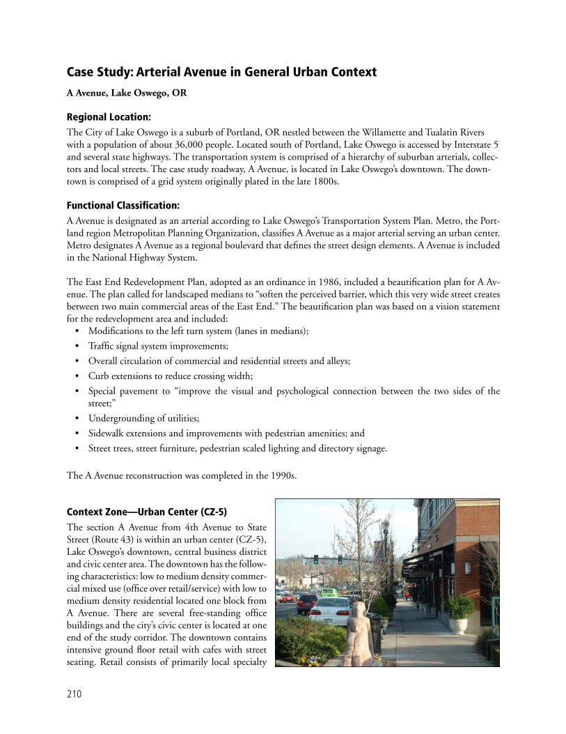
210
Case Study: Arterial Avenue in General Urban Context
A Avenue, Lake Oswego, OR
Regional Location: The City of Lake Oswego is a suburb of Portland, OR nestled between the Willamette and Tualatin Rivers with a population of about 36,000 people. Located south of Portland, Lake Oswego is accessed by Interstate 5 and several state highways. The transportation system is comprised of a hierarchy of suburban arterials, collec-tors and local streets. The case study roadway, A Avenue, is located in Lake Oswego’s downtown. The down-town is comprised of a grid system originally plated in the late 1800s.
Functional Classifi cation: A Avenue is designated as an arterial according to Lake Oswego’s Transportation System Plan. Metro, the Port-land region Metropolitan Planning Organization, classifi es A Avenue as a major arterial serving an urban center. Metro designates A Avenue as a regional boulevard that defi nes the street design elements. A Avenue is included in the National Highway System.
The East End Redevelopment Plan, adopted as an ordinance in 1986, included a beautifi cation plan for A Av-enue. The plan called for landscaped medians to “soften the perceived barrier, which this very wide street creates between two main commercial areas of the East End.” The beautifi cation plan was based on a vision statement for the redevelopment area and included:
• Modifi cations to the left turn system (lanes in medians);
• Traffi c signal system improvements;
• Overall circulation of commercial and residential streets and alleys;
• Curb extensions to reduce crossing width;
• Special pavement to “improve the visual and psychological connection between the two sides of the street;”
• Undergrounding of utilities;
• Sidewalk extensions and improvements with pedestrian amenities; and
• Street trees, street furniture, pedestrian scaled lighting and directory signage.
The A Avenue reconstruction was completed in the 1990s.
Context Zone—Urban Center (CZ-5)The section A Avenue from 4th Avenue to State Street (Route 43) is within an urban center (CZ-5), Lake Oswego’s downtown, central business district and civic center area. The downtown has the follow-ing characteristics: low to medium density commer-cial mixed use (offi ce over retail/service) with low to medium density residential located one block from A Avenue. There are several free-standing offi ce buildings and the city’s civic center is located at one end of the study corridor. The downtown contains intensive ground fl oor retail with cafes with street seating. Retail consists of primarily local specialty

211
shops and some national retailers. Upper fl oors are a mix of professional offi ces and personal services. Building height is primarily single story but newer development is two to three stories. Older build-ings have a 5–20-ft. setback (with small parking lots in front), but all of the new development has no setback with parking located in rear lots, or struc-tures.
Surrounding Land UsesThe downtown core is surrounded by older low-density single-family residential and medium density multi-family development. The A Avenue corridor transitions from an urban center at the east end to a single family residential at its west end. Adjacent and cross streets contain a mix of retail, hotel, restaurant and residential uses.
Thoroughfare ElementsFunctional class: Major arterialJurisdiction: City Through lanes: 4 Turn lanes: Center left-turn laneMedian: RaisedSidewalks: Both sides Planting strip: Tree grates in sidewalk and
planting stripsSpeed limit: 25 mphDrainage: Urban, curb and gutterParking: ParallelBicycle lanes: NoneTransit: Local/limited routesADT: 24,000
Land Use/Street IntegrationLivability Features
• Sidewalks vary from 8 to 15 ft. in width.
• Each block contains several pieces of public art.
• Ample and well-placed street furniture, benches.
• Most building entries at back of sidewalk.
• Good street connectivity on older grid of streets.
• Some cafes with outdoor seating (mostly on side streets).
• Pedestrian scaled lighting/urban design features including monuments, walls and built in plazas.
• Well-maintained street trees and indigenous landscaping in median, planting strips and grated treewells.
• On-street parking, street trees and urban design features buffer sidewalk from travel lanes.
• Attention to detail in streetscape amenities.

212
• Public and private investment in streetscape, including private provision and maintenance of planters and landscaping.
Mobility Features
• Local bus routes.
• Access management (buildings are rear ac-cessed, median, grid system and some alleys).
• Access to historic Willamette Trolley con-necting Lake Oswego to Portland.
Safety Characteristics
• Use of alternative paving for crossings and parking lanes.
• Curb extensions.
• Raised intersection at central cross street.
• Raised median serves as pedestrian refuge.
• Street trees, planters and parallel parking shel-ter pedestrians from passing cars.
• Bollards and low iron fencing separate pedes-trians at curb returns and narrow segments of sidewalk.
Strengths and SuccessesA Avenue is a functional and highly attractive ma-jor urban thoroughfare that may be considered an exemplary application of streetscape and urban de-sign. While the context and adjacent land uses con-tinue to evolve, the thoroughfare provides a popular multimodal community asset.
Factors in the Success of A Avenue• Adoption of a redevelopment plan that included a beautifi cation plan for A Avenue.
• Careful attention to the urban design, public art and aesthetics of the street creating a desirable walking environment.
• Maximization of on-street parking (parallel on A Avenue and diagonal on some cross streets).
• Private participation and investment in streetscape and care and maintenance of landscaping.
• The downtown is part of the East End Commercial Zoning District.

213
CSD Elements to StrengthenThe design of the thoroughfare is very well done and little improvement can be made. Over time re-development of the adjoining land will need to re-duce setbacks, intensify uses and increase building height to create a more defi ned street enclosure.
Typical Cross-SectionSidewalk width retail areas: 8–15 ft.Planting strip 4–7 ft. and treewells on both sides: 4 ft. by 4 ft.Parking lane: 8 ft. Outside travel lane: 11 ft.Inside travel lane: 10 ft. Median/turn lane: 10–12 ft.
median, 10 ft. turn lane
AcknowledgmentsCity of Lake Oswego Community Development, Redevelopment and Engineering DepartmentsTom Kloster, Metro

215
A P P E N D I C E S

neighborhoods, distributing trips from the arterials through the area to the ultimate destination. Collec-tor streets also collect traffi c from local streets in resi-dential neighborhoods and channel it into the arterial system. In the central business district, and in other areas of like development and traffi c density, the col-lector system may include the street grid that forms a logical entity for traffi c circulation.
Community—A group of people living within a de-fi ned geographic area or political boundary such as a neighborhood, district, town, city, or region. It is both a physical place of streets, buildings, schools and parks and a socio-economic structure, often defi ned by qualities including social traits, values, beliefs, cul-ture, history, government structure, issues of concern and type of leadership.
Community Livability—Refers to the environmen-tal and social quality of an area as perceived by resi-dents, employees, customers and visitors, including safety and health, local environmental conditions, quality of social interactions, opportunities for recre-ation and entertainment, aesthetics and existence of unique cultural and environmental resources. Context—The nature of the natural or built environ-ment created by the land, topography, natural features, buildings and associated features, land use types, and activities on property adjacent to streets and on side-walks and a broader area created by the surrounding neighborhood, district, or community. Context also refers to the diversity of users of the environment.
Context Sensitive Solutions (CSS) —Collaborative, interdisciplinary process that involves all stakeholders to design a transportation facility that fi ts its applica-ble setting and preserves scenic, aesthetic, historic and environmental resources while maintaining safety and mobility. CSS respects design objectives for safety, ef-fi ciency, capacity and maintenance while integrating community objectives and values relating to compat-ibility, livability, sense of place, urban design, cost and environmental impacts.
Accessibility—The ability to physically reach desired destinations, services and activities.
Access Management—The management of the in-terference with through traffi c caused by traffi c enter-ing, leaving and crossing thoroughfares. It is also the control and regulation of the spacing and design of driveways, medians, median openings, traffi c signals and intersections on arterial streets to improve safe and effi cient traffi c fl ow on the road system.
Arterial—A street that typically emphasizes a high level of traffi c mobility and a low level of access to land. Arterials accommodate relatively high levels of traffi c at higher speeds than other functional classes and serve longer distance trips. Arterial streets serve major centers of activity of a metropolitan area and carry a high proportion of the total urban area travel. Arterials also serve signifi cant intra-area travel, such as between central business districts and outlying resi-dential areas, between major inner city communities or major suburban centers. Arterial streets carry im-portant intra-urban as well as intercity bus routes.
Articulation—An architectural term that refers to di-viding building facades into distinct parts that reduce the appearance of the building’s mass adjacent to the sidewalk, identify building entrances and minimize uninviting blank walls.
Bicycle Boulevard—A roadway that motorists may use, but it prioritizes bicycle traffi c through the use of various treatments. Through motor vehicle traffi c is discouraged by periodically diverting it off the street. Remaining traffi c is slowed to approximately the same speed as bicyclists. STOP signs and signals on the bicy-cle boulevard are limited to the greatest extent possible, except when aiding bicyclists in crossing busy streets.
Collector—A street that typically balances traffi c mobility and access to land. Collector streets provides both land access service and traffi c circulation within residential neighborhoods, commercial and indus-trial areas. Collector streets pass through residential
217
I A p p e n d i x
Glossary of Terms

218
Context Zone—One of a set of categories used to describe the overall character of the built and natu-ral environment, building from the concept of the “transect”—a geographical cross section through a sequence ranging from the natural to the highly ur-banized built environment. There are six context zones plus special districts describing the range of environments including four urban context zones for the purpose of CSS—suburban, general urban, urban center and urban core.
Control Vehicle—A vehicle that infrequently uses a facility and must be accommodated, but encroach-ment into the opposing traffi c lanes, multiple-point turns, or minor encroachment into the roadside is acceptable. A condition that uses the control vehicle concept arises where occasional large vehicles turn at an intersection with low opposing traffi c volumes (such as, a moving van in a residential neighborhood or once per week delivery at a business) or where large vehicles rarely turn at an intersection with moderate to high opposing traffi c volumes (such as, emergency vehicles).
Corridor—A transportation pathway that provides for the movement of people and goods between and within activity centers. A corridor encompasses single or multiple transportation routes or facilities (such as thoroughfares, public transit, railroads, highways, bikeways, etc.), the adjacent land uses and the con-necting network of streets.
Corridor plan—Document that defi nes a compre-hensive package of recommendations for managing and improving the transportation system within and along a specifi c corridor, based upon a 20-year plan-ning horizon. Recommendations may include any ef-fective mix of strategies and improvements for many modes.
Corridor planning—Process that is collaborative with local governments and includes extensive public participation opportunities. A corridor may be di-vided into logical, manageable smaller areas for the purpose of corridor planning.
Design Control—Factors, physical and operational characteristics and properties that control or signifi -cantly infl uence the selection of certain geometric de-sign criteria and dimensions. Design speed, traffi c and pedestrian volumes and sight distance are examples of design controls.
Design Vehicle—Vehicle that must be regularly ac-commodated without encroachment into the oppos-ing traffi c lanes. A condition that uses the design ve-hicle arises where large vehicles regularly turn at an intersection with high volumes of opposing traffi c (such as, a bus route).
Edge Zone—The area between the face of curb and furnishing zone, an area of required clearance between parked vehicles or traveled way and appurtenances or landscaping.
Environment—The natural and built places within or surrounding a community. The natural environ-ment includes the topography, natural landscape, fl ora and fauna, streams, lakes and watersheds, and other natural resources, while the human/built envi-ronment includes the physical infrastructure of the community, as well as its institutions, neighborhoods, districts, and historical and cultural resources.
Frontage Zone—The distance between the through-way and the building front or private property line that is used to buffer pedestrians from window shop-pers, appurtenances and doorways. It contains private street furniture, private signage, merchandise displays, etc. The frontage zone can also be used for street cafes. This zone is sometimes referred to as the “shy” zone.
Functional Classifi cation—A system in which streets and highways are grouped into classes according to the character of service they intended to provide.
Furnishings Zone—The area of the roadside that provides a buffer between pedestrians and vehicles. It contains landscaping, public street furniture, transit stops, public signage, utilities, etc.
Human Scale—How humans perceive the size of their surroundings and their comfort with the ele-ments of the natural and built environment relative to their own size. In urban areas, human scale represents

219
features and characteristics of buildings that can be observed within a short distance and at the speed of a pedestrian, and sites and districts that are walkable. In contrast, auto scale represents a built environment where buildings, sites, signs, etc. are designed to be observed and reached at the speed of an automobile.
Intermodal—Refers to the connections between transportation modes.
Intersection—Where two or more public streets meet. They are characterized by a high level of ac-tivity and shared use, multi-modal confl icts, complex movements and special design treatments.
Local Street—Streets with a low level of traffi c mobil-ity and a high level of land access, serving residential, commercial and industrial areas. Local governments typically have jurisdiction for these streets.
Major Thoroughfare—As defi ned for this report, major streets (and rights-of-way, including improve-ments between the pavement edge and right-of-way line) in urban areas that fall under the conventional functional classes of arterials and collector streets. Thoroughfares are multimodal in nature and are de-signed to integrate with and serve the functions of the adjacent land uses.
Mixed-Use—The combining of, or zoning for, retail/commercial and/or service uses with residential or of-fi ce use in the same building or on the same site either vertically (with different uses stacked upon each other in a building) or horizontally (with different uses ad-jacent to each other or within close proximity).
Mobility—The movement of people or goods within the transportation system.
Multimodal—Refers to the availability of transporta-tion options within a system or corridor whether it be walking, bicycling, driving, or transit.
New Urbanism—A multi-disciplinary movement dedicated to restoring existing urban centers and towns within metropolitan regions, re-confi guring sprawling suburbs into real neighborhoods and diverse districts, conserving natural environments and preserving a community’s built legacy. The new urbanist vision is
to transform sprawl and establish compact, walkable, sustainable neighborhoods, streets and towns.
Placemaking—A holistic and community-based ap-proach to the development and revitalization of cit-ies and neighborhoods. Placemaking creates unique places with lasting value that are compact, mixed-use and pedestrian and transit oriented, and have a strong civic character.
Public Participation—A collaborative process that encourages stakeholders to participate in the forma-tion, evaluation and conclusion of a plan or transpor-tation improvement project.
Right-of-Way—The publicly owned land within which a thoroughfare can be constructed. Outside of the right-of-way the land is privately owned and can-not be assumed to be available for thoroughfare con-struction without acquiring the land through dedica-tion or purchase.
Roadside—The public right-of-way, which typi-cally includes the planting area and sidewalk, from the back of the curb to the front property line of ad-joining parcels. The roadside is further divided into a series of zones that emphasize different functions including the frontage, throughway, furnishings and edge zones. Transportation facilities, including bus shelters, waiting areas and bicycle parking, may be part of the roadside.
Safety—A condition of being safe, free from dan-ger, risk, or injury. In traffi c engineering, safety in-volves reducing the occurrences of crashes, reducing the severity of crashes, improving crash survivability, developing programmatic safety programs and apply-ing appropriate design elements in transportation im-provement projects.
Sight Distance—Distance that a driver can see ahead in order to observe and successfully react to a hazard, obstruction, decision point, or maneuver.
Smart Growth—Land use development practices that create more resource effi cient and livable com-munities, with accessible land use patterns. It is an alternative to sprawl development patterns.

220
Stakeholders—Groups or individuals that have an interest (stake) in the outcome of the planning or project development process. Typical stakeholders include elected offi cials, appointed commissioners, metropolitan planning organizations, state and lo-cal departments of transportation, transit authorities, utility companies, business interests, neighborhood associations and the general public.
Throughway Zone—The walking zone that must remain clear both horizontally and vertically for the movement of pedestrians.
Traditional Urban Environments—Places with development pattern, intensity and design charac-teristics that combine to make frequent walking and transit use attractive and effi cient choices, as well as provide for automobiles and convenient and accessi-ble parking. Traditional urban environments typically have mixed land uses in close proximity to one anoth-er, building entries that front directly on the street, building, landscape, and thoroughfare design that is pedestrian-scale, relatively compact development, a highly-connected, multimodal circulation network, usually with a fi ne “grain” created by relatively small blocks, thoroughfares and other public spaces that contribute to “placemaking” (the creation of unique locations that are compact, mixed-use, and pedestrian and transit oriented, that have a strong civic character and with lasting economic value).
Transect—A continuum of contexts ranging from the natural and agricultural (parks, open space, farmland) to varying intensities of urbanism (from suburban to urban core). The transect is the basis for the four ur-ban context zones used in this guidance.
Transitions—A change in thoroughfare type, context (for example, rural to urban), right-of-way width, number of lanes, or neighborhood or district. Geo-metrically, transitions refer to the provision of a proper smooth taper where lanes or shoulders change width, lanes diverge or merge, or lanes have been added or dropped.
Traveled Way—The public right-of-way between curbs, including parking lanes, and the travel lanes for private vehicles, goods movement, transit vehicles and bicycles. Medians, turn lanes, transit stops and exclusive transit lanes, curb and gutter, and loading/unloading zones are included in the traveled way.
Urban Area—As defi ned by federal-aid highway law (Section 101 of Title 23, U.S. Code) urban area means an urbanized area as an urban place as desig-nated by the Bureau of the Census having a popula-tion of 5,000 or more.
Values—Attributes and characteristics regarded by a community as having ultimate importance, signifi -cance, or worth. Community values encompass the natural and built environment, its social structure, people and institutions. The term often refers to a set of principles, standards, or beliefs concerning the elements of the community that are of ultimate im-portance.
Vision—Part of the process of planning a commu-nity that involves residents looking into the future, thinking creatively and establishing what they want their community to be in a 20- or 50-year plan-ning horizon. A vision describes an ideal picture and guides goal-setting, policies and actions by helping to understand community concerns, prioritize issues, determine necessary actions and identify indicators to measure progress.
Walkable—Streets and places designed or recon-structed to provide safe and comfortable facilities for pedestrians, and are safe and easy to cross for people of all ages and abilities. Walkable streets and places provide a comfortable, attractive and effi cient envi-ronment for the pedestrian including an appropriate separation from passing traffi c, adequate width of roadside to accommodate necessary functions, pedes-trian-scaled lighting, well-marked crossings, protec-tion from the elements (such as, street trees for shade, awnings or arcades to block rain), direct connections to destinations in a relatively compact area, facilities such as benches, attractive places to gather or rest such as plazas and visually interesting elements (such as, urban design, streetscapes, architecture of adjacent buildings).

221
Walkable Communities—Walkable communities are desirable places to live, work, learn and play, and therefore a key component of smart growth. Their desirability comes from two factors. First, locating, within an easy and safe walk, goods (such as housing, offi ces and retail) and services (such as transporta-tion, schools, libraries) that a community resident or employee needs on a regular basis. Second, by defi ni-tion, walkable communities make pedestrian activity possible, thus expanding transportation options and creating a streetscape that better serves a range of us-ers—pedestrians, bicyclists, transit riders and drivers. To foster walkability, communities must mix land uses and build compactly, and ensure safe and invit-ing pedestrian corridors.
Additional Sources of Defi nitions
Victoria Transport Policy Institute. TDM Encyclo-pedia Glossary. May 10, 2005. www.vtpi.org/tdm/tdm61.htm.
Federal Highway Administration. FHWA Functional Classifi cation Guidelines, Section II. Concepts, Defi -nitions, and System Characteristics. April 2000. www.fhwa.dot.gov/planning/fcsec2_1.htm.
Metropolitan Transportation Commission (San Fran-cisco Bay Area). Arterial Operations Program Ped/Bike Safety Toolbox. April 2003. www.bayareatraffi c-signals.org/toolbox/Tools/BikeBlvd.html

American Association of State Highway and Transportation Offi cials
Accommodating Utilities Within Highway Right-of-Way. October 2005.
A Policy on Geometric Design of Highways and Streets. 2001.
Guide for Achieving Flexibility in Highway Design. July 2004.
Guide for the Planning, Design and Operation of Pedestrian Facilities. July 2004.
Guide for the Development of Bicycle Facilities. 1999.
Roadside Design Guide. 2002.
Institute of Transportation Engineers
Colman, Steve. Planning Urban Arterial and Freeway Systems: An ITE Recommended Practice. 1997.
Design and Safety of Pedestrian Facilities, A Recom-mended Practice. March 1998.
Lalani, Nazir. Alternative Treatments for At-Grade Pe-destrian Crossings. 2001.
Nabti, Jumana and Matthew Ridgway. Innovative Bi-cycle Treatments. May 2002.
Neighborhood Street Design Guidelines. 2003
Review of Planning Guidelines and Design Standards for Bicycle Facilities. 1996.
Traditional Neighborhood Development Street Design Guidelines. June 1997.
Traffi c Engineering for Neo-Traditional Neighborhood Design. 1994.
Federal Highway Administration
Flexibility in Highway Design. 1997. www.fhwa.dot.gov/environment/fl ex/index.htm.
Pedestrian Facilities Users Guide—Providing Safety and Mobility. March 2002.
Roundabouts: An Informational Guide. June 2000.
Selecting Roadway Design Treatments to Accommodate Bicycles. 1994.
The Effects of Innovative Pedestrian Signals at Unsignal-ized Locations. August 2000.
The Effects of Traffi c Calming Measures on Pedestrian and Motorist Behavior. August 2001.
Zegeer, Charles. Safety Effects of Marked vs. Unmarked Crosswalks at Uncontrolled Locations: Executive Sum-mary and Recommended Guidelines. 2002.
Transportation Research Board
Access Management Manual. November, 2003.
CH2M Hill. A Guide for Addressing Collisions with Trees in Hazardous Locations, NCHRP Draft Final Guide. December 2002.
Fitzpartrick, Kay et al., TCRP Report 65: Evaluation of Bus Bulbs. 2001.
Fitzpartrick, Kay and Mark Woolridge. NCHRP Syn-thesis 299: Recent Geometric Design Research for Im-proved Safety and Operations. 2001.
II A p p e n d i x
Bibliography
223

224
NCHRP Report 435: Guidebook for Transportation Corridor Studies: A Process for Effective Decision-Mak-ing. 1999.
NCHRP Report 500: A Guide for Addressing Collisions with Trees in Hazardous Locations. 2003.
NCHRP Synthesis 264: Modern Roundabout Practice in the United States. 1998.
Neuman, Timothy R., Marcy Schwartz, Leofwin Clark, and James Bednar. NCHRP Report 480: A Guide to Best Practices for Achieving Context Sensitive Solutions. 2002.
Texas Transportation Institute. NCHRP Report 19: Guidelines for the Location and Design of Bus Stops. 1996.
State Departments of Transportation
California Department of Transportation. Main Streets: Flexibility in Design and Operations. Caltrans, July 2002.www.dot.ca.gov/hq/oppd/guidance.htm.
Florida Department of Transportation. Bicycle Facili-ties Planning and Design Handbook. Tallahassee, FL, July 1999.
Ewing, Reid, and Michael King. Flexible Design of New Jersey’s Main Streets. Prepared by the Voorhees Transportation Policy Institute Rutgers University for the New Jersey Department of Transportation, De-cember 2001.
Maryland Department of Transportation. When Main Street is a State Highway: A Handbook for Communi-ties and Designers. www.sha.state.md.us/ohd/mainstreet.htm
Minnesota Department of Transportation. Access Management Policy: Highway Access Category System and Spacing Guidelines. March 2002.
Minnesota Department of Transportation. Minnesota Bicycle Transportation Planning and Design Guidelines. June 1996.www.dot.state.mn.us/sti/mg1004.pdf
New Jersey Department of Transportation. Pedestrian Compatible Planning and Design Guidelines. safety.fhwa.dot.gov/fourthlevel/design_p.htm
Oregon Department of Transportation. Main Street…When a Highway Runs Through It: A Handbook for Oregon Communities. November 1999.
Oregon Department of Transportation. Oregon Bi-cycle and Pedestrian Plan. 1995.
Otak, Inc. Pedestrian Facilities Guidebook: Incorporat-ing Pedestrians Into Washington’s Transportation System. Washington State Department of Transportation. September 1997.
Additional Resources
Appleyard, Donald. Livable Streets. Los Angeles: Uni-versity of California Press, 1981.
Bicycle Federation of America Campaign to Make America Walkable. Creating Walkable Communities: A Guide for Local Governments. December 1998. safety.fhwa.dot.gov/ped_bike/docs/marc.pdf
City of San Diego. Street Design Manual. May 2002. www.sannet.gov/planning
Congress For the New Urbanism. Civilizing Down-town Highways. Local Government Commission, 2002.
Dock, Frederick, William Morrish and Carol Swen-son. Design/Development Principles for Livable Sub-urban Arterial Roadways. Minnesota Department of Transportation, June 2001.
Duany Plater-Zyberk & Company. Smart Code v. 2.6. Transect Codeware Company, July 5, 2002.
Jacobs, Allan B. et al. The Boulevard Book. Cambridge, MA: Massachusetts Institute of Technology, 2001.

225
Jacobs, Allan B. et al. Multiple Roadway Boulevards: Case Studies, Designs and Design Guidelines. Univer-sity of California Berkeley: Institute of Urban and Re-gional Planning, November 1995.
Metro Regional Services (Portland). Creating Livable Streets: Street Design Guidelines for 2040. www.metro-region.org/article.cfm?ArticleID=261
Orange County Transportation Authority. Bus Stop Safety and Design Guidelines. Kimley-Horn and As-sociates Inc., 2004.
Portland Offi ce of Transportation. Portland Pedestrian Design Guide. June 1998. www.trans.ci.portland.or.us/DesignReferences/Pe-destrian/INDEX.PDF
Santa Clara Valley Transportation Authority. Bicycle Technical Guidelines—A Guide for Local Agencies in Santa Clara County. September 1999.
Santa Clara Valley Transportation Authority. Com-munity Design and Transportation—A Manual of Best Practices for Integrating Transportation and Land Use. October, 2001.
Santa Clara Valley Transportation Authority. Pedes-trian Technical Guidelines—A Guide to Planning and Design for Local Agencies in Santa Clara County. Oc-tober 2003.
Tri-County Metropolitan Transportation District. Planning and Design for Transit. Portland, Oregon, 1993.
Western Australia Planning Commission. Liv-able Neighborhoods: Street Layout, Design and Traffi c Management Guidelines. June 2000. www.planning.wa.gov.au/publications/27.aspx