An Investigation the Effects of Geometric Tolerances on...
9
Journal of Applied and Computational Mechanics, Vol. 1, No. 2, (2014), 103-111 An Investigation the Effects of Geometric Tolerances on the Natural Frequencies of Rotating Shafts Ali Akbar Ansarifard 1 , Abdolrahman Jaamialahmadi 2 1 MSc. Mechanical Student, Amirkabir University of Technology, Hafez Street, Tehran, [email protected] , 2 Assistant Prof. of Mechanical Engineering Department, Ferdowsi University of Mashhad, Azadi Square, Mashhad, jaami-[email protected] Abstract This paper presents the effects of geometric tolerances on the rotating shafts natural frequencies. Due to modeling the tolerances, a code is written in MATLAB 2013 software that produces deviated points. Deviated points are controlled by different geometric tolerances, including cylindricity, total run-out and coaxiality tolerances. Final surfaces and models passing through the points are created using SolidWorks 2013 software and finally modal analysis is carried out with the FE software. It is observed whatever the natural frequency is higher or the geometric tolerances are greater, the real and ideal shafts natural frequencies are more distant. Also difference percentage between ideal and real frequencies is investigated. The results show that the percentage value is approximately constant for every mode shapes. Keywords: Geometric tolerance, Natural frequency, Critical rotational speed, Rotating shafts, Modal analysis. 1. Introduction Today, high rotational speed shafts are very applicable especially in rapid pump and turbomachinery industries. Investigating the natural frequency of rotating shafts is necessary in designing of shafts. In order to comply with safety lines to prevent failure due the deflections over the allowable limit, applying rotational speeds close to the critical speeds are avoided. In the manufacturing processes, creation of pieces with no tolerance in the view of dimension and geometry, will be very difficult and expensive and its value depends on the performance characteristics of the piece. In general, manufacturing the parts with relative motions compared to each other, should be more accurate than the fixed parts. Moving parts are always being excited by applied loads and if the frequency of the applied loads becomes equal to one of the natural frequencies of the moving parts, the resonance phenomenon occurs. Therefore themanufacturing process should be such a way that the final product be ever closer to the ideal target. Then natural frequencies of produced models can be estimated by obtaining natural frequencies of ideal models from the possible methods and then necessary forecasts and preventions can be performed. These frequencies are known as the critical rotational speeds in rotating shafts. Today, the critical rotational speed is highly regarded and the damping system should be designed such a way that damps the extremely large lateral forces acting on the bearings during the resonance. When the rotational speed of rotating shafts is high, any defects and deviations in the geometry and material of the system, could bring destructive events. Lots of researchers have studied the vibrations of rotating shafts with the effects of different parameters such as misalignment, unbalancing, clearance and cracks. Xu and Maragoni [1] developed a theoretical model of a complete motor-flexible coupling-rotor system capable of describing the mechanical vibration resulting from misalignment and unbalance. They presented that the vibrations induced by misalignment are amplified into major vibration sources. They also validated the results by some experimental Received May 20 2014; revised August 24 2014;accepted for publication September 05 2014. Corresponding author: Ali Akbar Ansarifard, [email protected], [email protected]
Transcript of An Investigation the Effects of Geometric Tolerances on...
Journal of Applied and Computational Mechanics, Vol. 1, No. 2, (2014), 103-111
An Investigation the Effects of Geometric Tolerances on the Natural Frequencies of Rotating Shafts
Ali Akbar Ansarifard1, Abdolrahman Jaamialahmadi2
1MSc. Mechanical Student, Amirkabir University of Technology,
Hafez Street, Tehran, [email protected],2
Assistant Prof. of Mechanical Engineering Department, Ferdowsi University of Mashhad,Azadi Square, Mashhad, [email protected]
Abstract
This paper presents the effects of geometric tolerances on the rotating shafts natural frequencies. Due tomodeling the tolerances, a code is written in MATLAB 2013 software that produces deviated points.Deviated points are controlled by different geometric tolerances, including cylindricity, total run-out andcoaxiality tolerances. Final surfaces and models passing through the points are created using SolidWorks2013 software and finally modal analysis is carried out with the FE software. It is observed whatever thenatural frequency is higher or the geometric tolerances are greater, the real and ideal shafts naturalfrequencies are more distant. Also difference percentage between ideal and real frequencies is investigated. The results show that the percentage value is approximately constant for every mode shapes.
Keywords: Geometric tolerance, Natural frequency, Critical rotational speed, Rotating shafts, Modal analysis.
1. Introduction
Today, high rotational speed shafts are very applicable especially in rapid pump and turbomachinery industries.Investigating the natural frequency of rotating shafts is necessary in designing of shafts. In order to comply withsafety lines to prevent failure due the deflections over the allowable limit, applying rotational speeds close to thecritical speeds are avoided. In the manufacturing processes, creation of pieces with no tolerance in the view ofdimension and geometry, will be very difficult and expensive and its value depends on the performancecharacteristics of the piece. In general, manufacturing the parts with relative motions compared to each other, shouldbe more accurate than the fixed parts. Moving parts are always being excited by applied loads and if the frequency of the applied loads becomes equal to one of the natural frequencies of the moving parts, the resonance phenomenonoccurs. Therefore themanufacturing process should be such a way that the final product be ever closer to the idealtarget. Then natural frequencies of produced models can be estimated by obtaining natural frequencies of idealmodels from the possible methods and then necessary forecasts and preventions can be performed. These frequencies are known as the critical rotational speeds in rotating shafts. Today, the critical rotational speed is highly regardedand the damping system should be designed such a way that damps the extremely large lateral forces acting on thebearings during the resonance.
When the rotational speed of rotating shafts is high, any defects and deviations in the geometry and material ofthe system, could bring destructive events. Lots of researchers have studied the vibrations of rotating shafts with theeffects of different parameters such as misalignment, unbalancing, clearance and cracks. Xu and Maragoni [1]developed a theoretical model of a complete motor-flexible coupling-rotor system capable of describing themechanical vibration resulting from misalignment and unbalance. They presented that the vibrations induced bymisalignment are amplified into major vibration sources. They also validated the results by some experimental
Received May 20 2014; revised August 24 2014;accepted for publication September 05 2014.Corresponding author: Ali Akbar Ansarifard, [email protected], [email protected]
Ali Akbar Ansarifard, Abdolrahman Jaamialahmadi Vol. 1, No. 2, 2014
Journal of Applied and Computational Mechanics, Vol. 1, No. 2, (2014), 103-111
104studies [2]. Lee et. al. [3] derived a dynamic model for misaligned rotor-ball bearing systems driven through aflexible coupling by treating the reaction loads and deformations at the bearing and coupling elements as themisalignment effect. They showed as the angular misalignment increases, the whirling orbits tend to collapse towarda straight line and the natural frequency of the misaligned rotor system associated with the misalignment directionincreases largely. Tejas et. al. [4] investigated the effect of misalignment on vibration response of coupled rotors.They modelled the coupled rotor system using Timoshenko beam elements with all six dof. They found that themisalignment couples vibrations in bending, longitudinal and torsional modes. They also presented experimentalinvestigations for validating the results [5]. Dimarogonas and Papadopoulos [6] investigated the vibration of crackedshafts in bending. They obtained analytical solutions for the closing crack under the assumption of large staticdeflections, a situation common in turbomachinery. Vibration and stability of a rotating shaft containing a transversecrack was studied by Huang et. al. [7]. The steady state responses and the stability criteria are then obtained, and theeffects of crack depth, crack location and rotational speed are discussed. It is discovered that the crack affects thedynamic response more significantly when it occurs near a place where the bending moment exhibits a larger value.Also the investigations of the dynamics of a rotor system with bearing clearance is presented by Flowers et. al. [8].Akturk [9] presented some characteristic parameters affecting the natural frequency of a rotating shaft supported bydefect-free ball bearings. He presented a new analytical investigation into the effects of preload, the number ofrolling elements and ball set position. So controlling the geometry of shafts and their involved rotating parts is veryimportant and geometric tolerances are more important and effective than dimensional tolerances. This paperinvestigates the effects of geometric tolerances of rotating shafts on the vibrations of rotating shafts. Tolerances ofthe bearings and the type of adaptation between shaft and bearings are not discussed here and rigid bearings with nodamping effects and friction are considered. Geometric tolerances associated with shafts are such as straightness,circularity, cylindricity, concentricity, coaxiality, circular run-out (radial) and total radial run-out tolerances [10-12].
The results of such an analysis would be useful in every system that has rotating shafts. But the presented studywill be more valuable for very sensitive and high speed systems that any deviation in critical rotational speed is veryimportant. Up to now, industrially-developed motors have normally reached 250,000 revolutions per minute [13].Some rotating shafts are supercritical that means their rotational speed goes further than the first critical rotationalspeed. So the effects of the tolerances on the higher natural frequencies than fundamental frequency, are investigatedtoo. This article aims to show the effects of geometric tolerances, by increasing the natural frequencies and modeshapes.
2. Implementation Method
In this paper three different rotating shafts from view of size and shape are considered:I) Rotating shaft with 50 mm diameter and 500 mm length.II) Rotating shaft with 50 mm diameter and 1,000 mm length.III) Step shaft including narrow section with 50 mm diameter and 300 mm length and stockish section with 66 mmdiameter and 600 mm length that is modeled from a real rotating shaft.
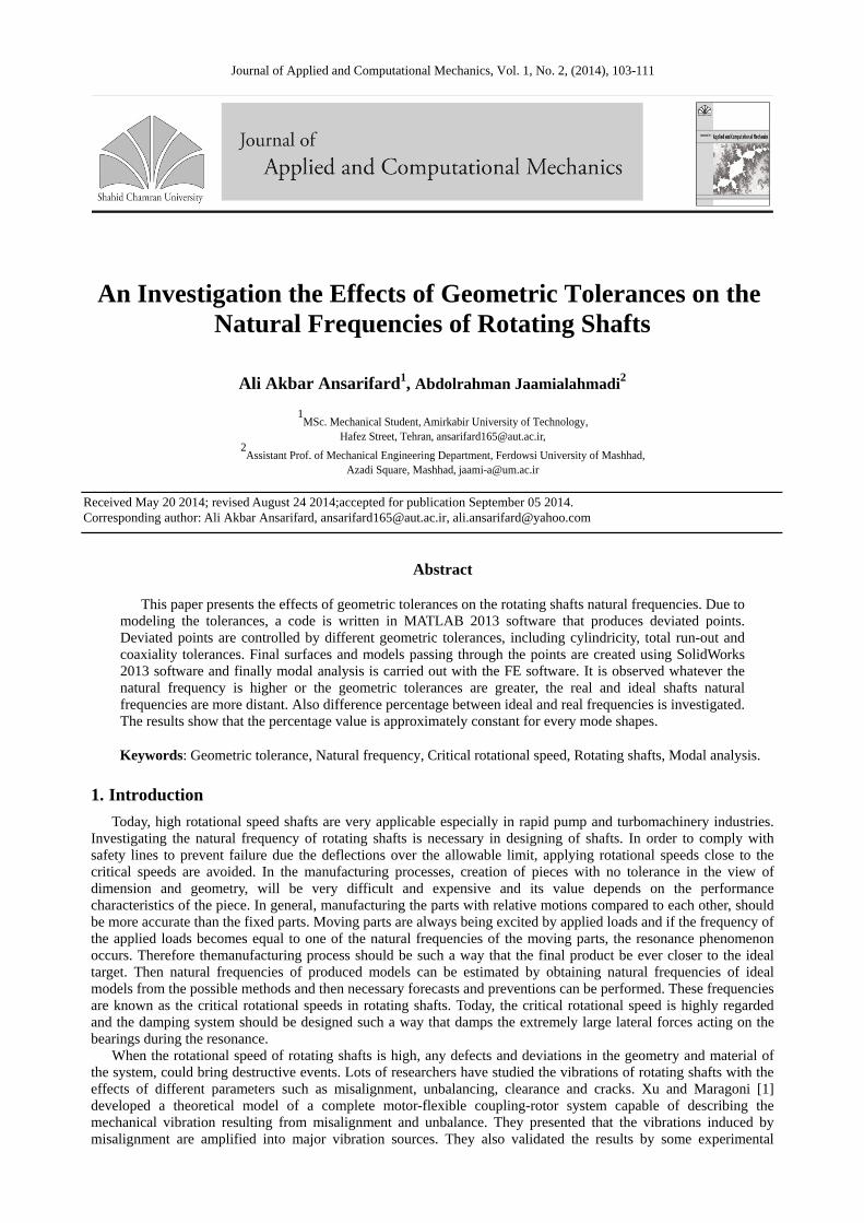
In the manufacturing processes of these presented shafts, three types of output deviated surfaces are considered.Specific geometric tolerances should be used for geometry controlling for each of these types. Here the kind oftolerance is less important, because each of these tolerances may contain another one too and also differenttolerances can be applied on a same type and relatively same results may be achieved. These types and relatedgeometric tolerances are followed in Fig. 1.
Fig. 1. Exaggerated output surface of manufacturing processes. a first manufacturing process cylindricity tolerance used.bsecond manufacturing process total radial run-out tolerance used. c third manufacturing process coaxiality tolerance used.
For the first type, the deviations generated from Ideal state are applied on specific sections along the axis ofrotation by a negative effect such a way that on each of these sections, based on a specified angle, deviations areconsidered on different points of the circumference of the cross section. Therefore the circumferences of thesesections are not uniform circles and have some deviations. For the second type, negative deviations on specificsections along the axis of rotation are applied only on the radius of the section circles. Therefore these sections areuniform circles and they only differ in size, from each other. In addition, centers of all these circles are located on the axis of ideal cylinder (datum axis). For the third type, the deviations are such a way that all sections are uniformcircles with a diameter equal to the ideal diameter, but the deviations are applied on the centers of the sections and
a) b) c)
An Investigation the Effects of Geometric Tolerances on the Natural Frequencies of Rotating Shafts
Journal of Applied and Computational Mechanics, Vol. 1, No. 2, (2014), 103-111
105the centers are not located on a straight line and they have distances from datum axis.
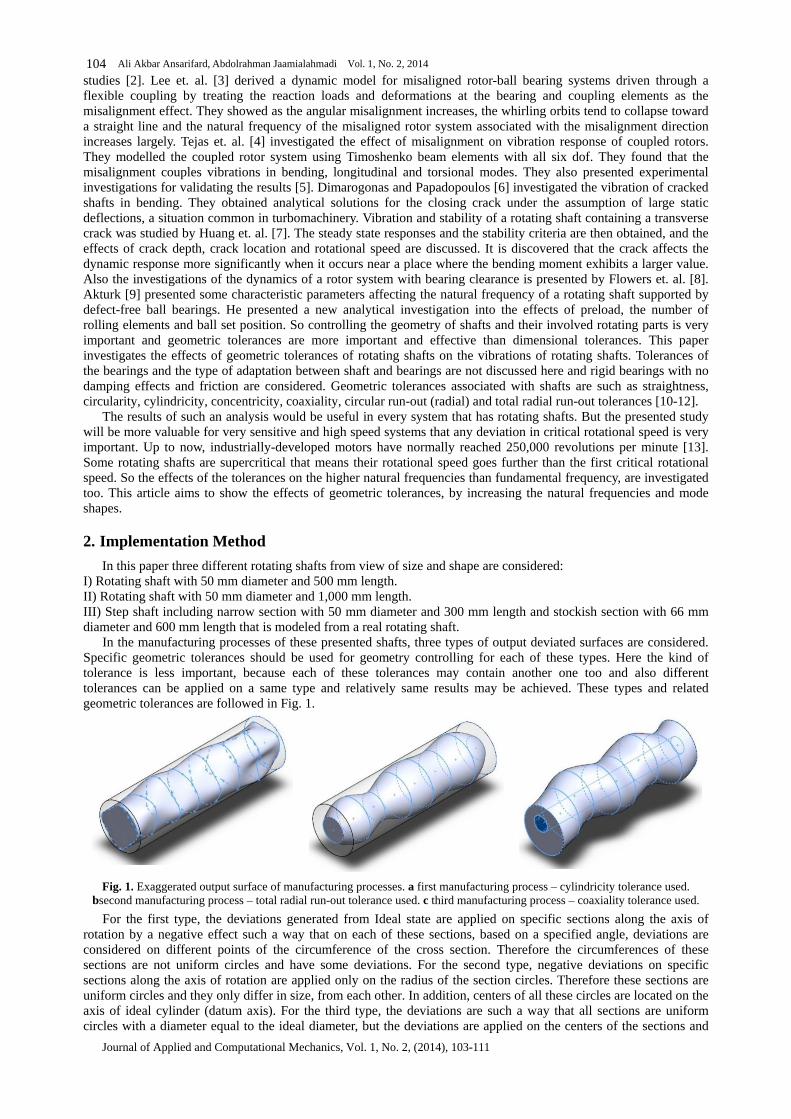
These three mentioned types for machining processes, are applied on the models. Modeling the deviations is done by generating a set of deviated points with the help of random numbers in MATLAB. Different types of deviationswith different tolerance values and different number of deviated points are applied on the mentioned rotating shafts.So the effects of these parameters on the natural frequencies will be investigated too. Furthermore to enhance theaccuracy of the results, several models will be created with the same conditions and the average of the results isconsidered as the final result. This will reduces the errors. Desired parameters are followed in Fig. 2.
Fig. 2. Displaying considerable parameters on the shaftWhere, e1 is the number of longitudinal sections and e2 is the number of points applying the deviations in every
section. For applying the deviations, a parameter called the diametric tolerance coefficient (Tc) will be used that isequal to the ratio of geometric tolerance to the shaft diameter. So for step shaft with a constant diametric tolerancecoefficient, surface deviation ranges of the shaft parts are different.
(1)For generating random numbers, standard normal distribution (Gaussian distribution) is used which the
probability density function includes =0 and =1. The intervals of the numbers generated by this function areinfinite, so for limiting them only the in the range [ -3 , +3 ] are acceptable. This range includes more than 99.7%of total generated numbers so its error can be neglected.
For example if the input for the diametric tolerance coefficient is 0.01 and the diameter of the shaft is 50mm, then the tolerance equals to 0.5mm that means the maximum deviation between the ideal points and generated points is0.5mm. After generating the deviated points, they are imported into the SolidWorks software. it is necessary to create closed curves passing through the points on the same longitudinal plane. After passing a cylindrical surface throughthese section curves, the external surface of the shafts may be created and finally the solid model could be createdeasily.
3. Analyzing the Models
Finite element method is used for estimating the natural frequencies. For this purpose, Ansys the commercial FEsoftware is used. Two dimensional quadratic order surface elements are used. Shafts are made of steel with thefollowing characteristics:
Table 1. Physical characteristics of presented shafts
Module of elasticity (N/m2) Poisson s ratio Density (Kg/m3)E = 2.1×1011 = 0.3 = 7800
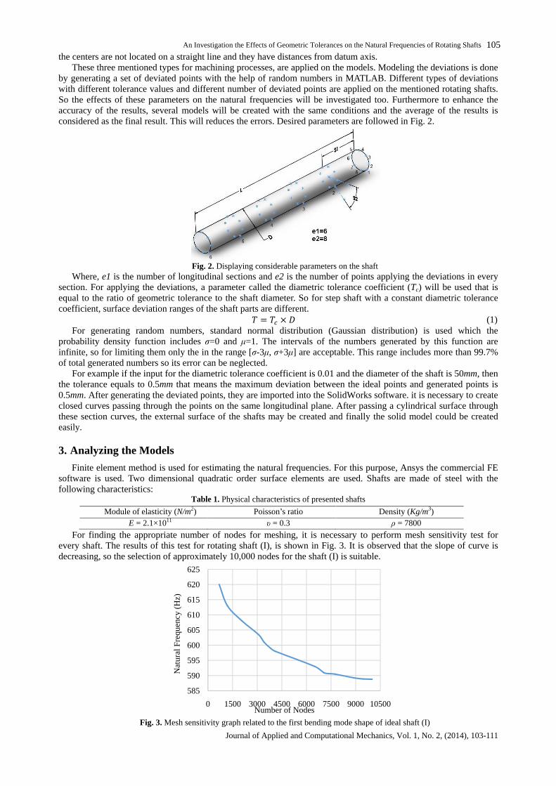
For finding the appropriate number of nodes for meshing, it is necessary to perform mesh sensitivity test forevery shaft. The results of this test for rotating shaft (I), is shown in Fig. 3. It is observed that the slope of curve isdecreasing, so the selection of approximately 10,000 nodes for the shaft (I) is suitable.
Fig. 3. Mesh sensitivity graph related to the first bending mode shape of ideal shaft (I)
585
590
595
600
605
610
615
620
625
0 1500 3000 4500 6000 7500 9000 10500
Nat
ural
Freq
uenc
y(H
z)
Number of Nodes
Ali Akbar Ansarifard, Abdolrahman Jaamialahmadi Vol. 1, No. 2, 2014
Journal of Applied and Computational Mechanics, Vol. 1, No. 2, (2014), 103-111
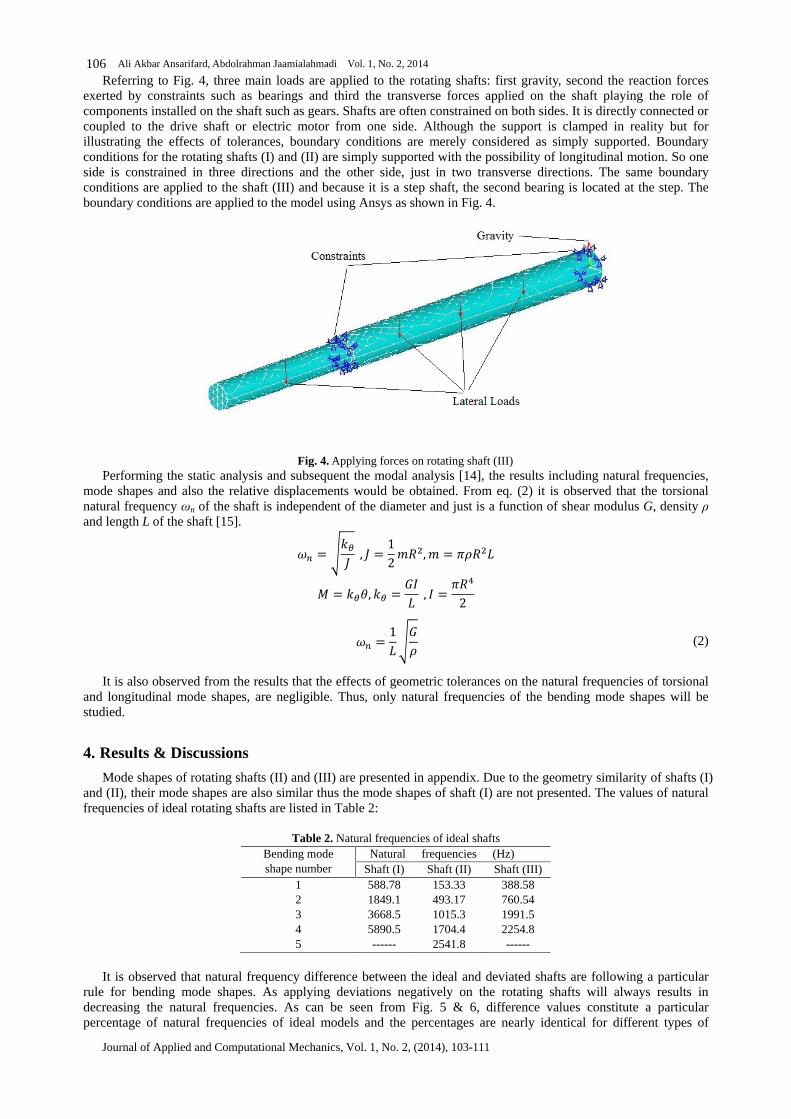
106Referring to Fig. 4, three main loads are applied to the rotating shafts: first gravity, second the reaction forces
exerted by constraints such as bearings and third the transverse forces applied on the shaft playing the role ofcomponents installed on the shaft such as gears. Shafts are often constrained on both sides. It is directly connected or coupled to the drive shaft or electric motor from one side. Although the support is clamped in reality but forillustrating the effects of tolerances, boundary conditions are merely considered as simply supported. Boundaryconditions for the rotating shafts (I) and (II) are simply supported with the possibility of longitudinal motion. So oneside is constrained in three directions and the other side, just in two transverse directions. The same boundaryconditions are applied to the shaft (III) and because it is a step shaft, the second bearing is located at the step. Theboundary conditions are applied to the model using Ansys as shown in Fig. 4.
Fig. 4. Applying forces on rotating shaft (III)Performing the static analysis and subsequent the modal analysis [14], the results including natural frequencies,
mode shapes and also the relative displacements would be obtained. From eq. (2) it is observed that the torsionalnatural frequency n of the shaft is independent of the diameter and just is a function of shear modulus G, densityand length L of the shaft [15].
(2)
It is also observed from the results that the effects of geometric tolerances on the natural frequencies of torsionaland longitudinal mode shapes, are negligible. Thus, only natural frequencies of the bending mode shapes will bestudied.
4. Results & Discussions
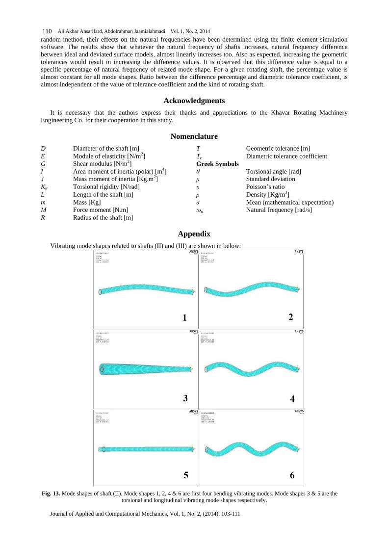
Mode shapes of rotating shafts (II) and (III) are presented in appendix. Due to the geometry similarity of shafts (I)and (II), their mode shapes are also similar thus the mode shapes of shaft (I) are not presented. The values of naturalfrequencies of ideal rotating shafts are listed in Table 2:
Table 2. Natural frequencies of ideal shaftsBending modeshape number
Natural frequencies (Hz)Shaft (I) Shaft (II) Shaft (III)
1 588.78 153.33 388.582 1849.1 493.17 760.543 3668.5 1015.3 1991.54 5890.5 1704.4 2254.85 ------ 2541.8 ------
It is observed that natural frequency difference between the ideal and deviated shafts are following a particularrule for bending mode shapes. As applying deviations negatively on the rotating shafts will always results indecreasing the natural frequencies. As can be seen from Fig. 5 & 6, difference values constitute a particularpercentage of natural frequencies of ideal models and the percentages are nearly identical for different types of
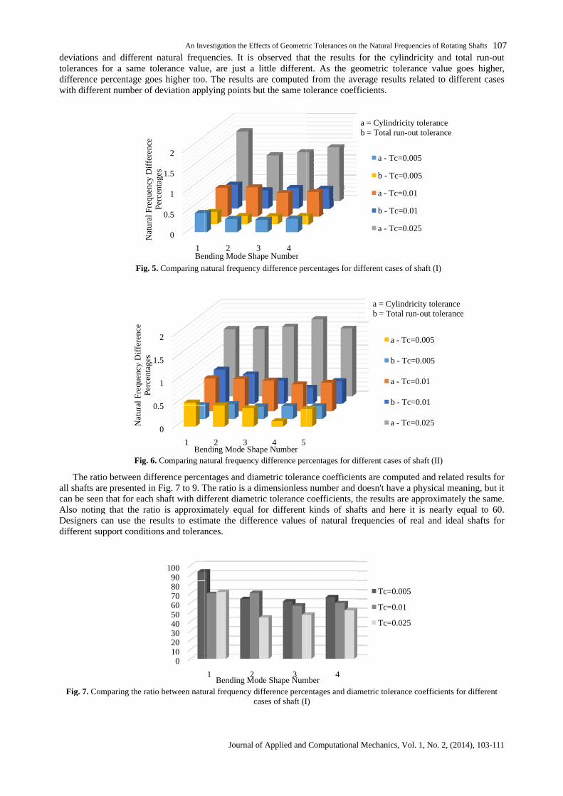
deviations atolerances fdifference pwith differen
The ratioall shafts arecan be seenAlso notingDesigners cdifferent sup
Fig. 7. Com
s and differents for a same to
percentage goerent number of d
Fig. 5
Fig. 6.
tio between diffare presented inen that for eachng that the rati
can use the resupport conditio
omparing the ratio
Nat
ural
Freq
uenc
yD
iffe
renc
ePe
rcen
tage
s
0
1
Nat
ural
Freq
uenc
yD
iffe
renc
ePe
rcen
tage
s
An Inv
nt natural frequtolerance value
goes higher too.of deviation appl
. 5. Comparing na
. 6. Comparing na
ifference percen in Fig. 7 to 9. Tch shaft with difatio is approximresults to estim
tions and toleran
atio between natu
0
0.5
1
1.5
2
1
Perc
enta
ges
Ben
0
0.5
1
1.5
2
1Ben
0102030405060708090
100
nvestigation the Eff
Journal o
quencies. It islue, are just aoo. The results applying points b
natural frequency
natural frequency
centages and dia. The ratio is a ddifferent diametrximately equaltimate the differrances.
tural frequency dc
2ending Mode Sha
2 3ending Mode Sha
1 2Bending Mo
Effects of Geometri
l of Applied and
is observed thaa little differen
ts are computeds but the same to
ncy difference per
cy difference per
diametric tolerana dimensionless etric tolerance c
al for differenterence values
y difference percecases of shaft (I)
3 4Shape Number
4 5hape Number
3ode Shape Num
tric Tolerances on t
Computational
hat the results frent. As the geed from the ave tolerance coeff
percentages for di
ercentages for dif
rance coefficienss number and de coefficients, thnt kinds of shafes of natural fre
rcentages and diam (I)
4mber
n the Natural Frequ
al Mechanics, Vo
ts for the cylindgeometric toleraaverage resultsefficients.
different cases of
different cases of
ients are computd doesn't have a, the results arehafts and here ifrequencies of
iametric tolerance
a - Tc=0.0
b - Tc=0.0
a - Tc=0.
b - Tc=0.
a - Tc=0.0
a - Tc
b - Tc
a - Tc
b - Tc
a - Tc
Tc=0.005
Tc=0.01
Tc=0.025
a = Cylindricitb = Total run-o
a = Cylindrb = Total ru
quencies of Rotatin
Vol. 1, No. 2, (20
indricity and tolerance value gts related to diff
of shaft (I)
of shaft (II)
uted and relatede a physical meare approximatele it is nearly ef real and idea
nce coefficients fo
0.005
0.005
.01
.01
0.025
Tc=0.005
Tc=0.005
Tc=0.01
Tc=0.01
Tc=0.025
05
25
city toleranceout tolerance
ndricity tolerancel run-out tolerance
ting Shafts
2014), 103-111
107total run-outgoes higher,
ifferent cases
ted results for eaning, but it
tely the same.equal to 60.
eal shafts for
for different
cence

Ali Ak
Journal of
108
Fig. 8. Co
Fig. 9. Co
As mentsufficient alorelated to thlots of timesof natural frepoints aboutpoints are exTherefore asthe mean va
Fig. 10By comp
deviation ofdifference frabout 0.04%
kbar Ansarifard, A
l of Applied and C
Comparing the ra
Comparing the ra
ntioned before talone and the dthe first naturales would result
frequencies betout the mean vaexpanded, the c
as the input app value based on t
10. Distribution cmparing the Figof normal curvfrom the mean
4% to 0.06% dif
Abdolrahman Jaam
Computational M
ratio between na
ratio between na
re to enhance thee data distributioral frequency ofults in differentetween the outpvalue. As prese curve goes do
applied deviationn the normal dis
n curve of output Fig. 10 with Figurve in Fig. 10an value and abdifferent from th
0
10
20
30
40
50
60
70
80
1B
01020304050607080
-0.08 -0.0Diff
aamialahmadi Vol
al Mechanics, Vol
natural frequencyca
natural frequencyca
the accuracy, avtion around theof shaft (I) withnt sets of pointsutput values andresented, wheredownward. Tren
tion was based odistribution too.
t results of the fiFig. 11 that is a10 is about 0.0about 27% of th the mean value
2Bending Mode S
1 2Bending M
0.06 -0.04 -ifference Percent
Outp
ol. 1, No. 2, 2014
ol. 1, No. 2, (201
cy difference perccases of shaft (II
cy difference perccases of shaft (IIIaverage of the rhe mean value sith Tc=0.005 are
ints. As shown, tnd mean value. re the points arrend of the poin
d on the normal oo.
e first natural freqs a normal dens0.02. Thereforef the results are 0lue.
3 4e Shape Number
3g Mode Shape Nu
-0.02 0entage of Natural tput Values and M
014), 103-111
ercentages and di(II)
ercentages and di(III)e results were pre should be presare presented inn, the horizontale. The vertical aare compact, th
oints is approximal distribution, t
equency of shaft (ensity function,re about 68% ore 0.02% to 0.04
5er
4 Number
0.02 0.04ral Frequencies Bed Mean Value
diametric toleran
diametric toleran
presented. In thresented. For exin Fig. 10. Runntal axis shows t
al axis just show, the curve goesximated by then, the output res
ft (I) with Tc=0.0n, it can be con
of the results.04% different, a
Tc=0.00
Tc=0.01
Tc=0.02
Tc=0.005
Tc=0.01
0.06 0.0 Between the
rance coefficients
rance coefficients
this case, meanexample the ou
unning the writts the differenceows the compacoes upward andhe normal densitresults are distrib
0.005 about the moncluded that thlts just have upt, and the rest o
005
.01
025
.08
nts for different
nts for different
an value isn toutput results
ritten code force percentageactness of the nd where thesity function.
tributed about
mean value.t the standardup to 0.02%
t of points are
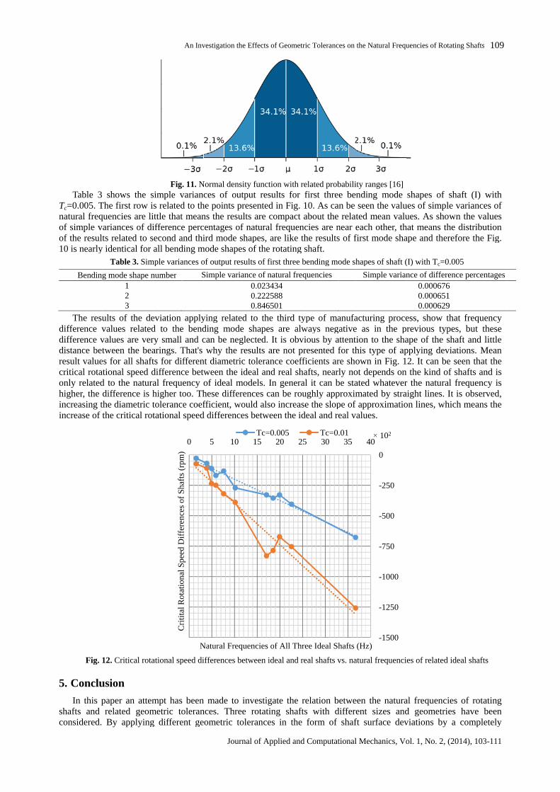
Table 3Tc=0.005. Thnatural frequof simple vaof the result10 is nearly
Bending
The resudifference vdifference vdistance betresult valuescritical rotatonly relatedhigher, the dincreasing thincrease of t
Fig. 1
5. Conclu
In this pshafts andconsidered.
3 shows the si. The first row isequencies are litvariances of dif
ults related to sely identical for a
Table 3. Simp
ing mode shape n123
esults of the devalues relatedvalues are very
between the beaues for all shaftstational speed ded to the naturae difference is h
the diametric tf the critical rot
. 12. Critical rota
lusion
s paper an attemd related geomd. By applying
An Inv
Fig. 11. Nosimple variancis related to thelittle that meandifference percesecond and thirr all bending mo
imple variances of
e number S
deviation applyted to the bendery small and cearings. That's
afts for differentdifference betw
ural frequency os higher too. Thc tolerance coeffrotational speed
tational speed dif
tempt has beenometric tolerancng different ge
0
Cri
tita
lRot
atio
nalS
peed
Dif
fere
nces
ofSh
afts
(rpm
)
N
nvestigation the Eff
Journal o
Normal density fances of outputthe points preseans the results arcentages of natthird mode shap mode shapes ofs of output results
Simple variance0.0.0.
lying related tonding mode shcan be neglect
t's why the resuent diametric toletween the ideay of ideal modeThese differenceefficient, would
ed differences be
differences betwe
en made to inveances. Three rogeometric tolera
5 10 1
Natural Frequenc
Effects of Geometri
l of Applied and
y function with reut results for fsented in Fig. 1
ts are compact anatural frequencapes, are like th of the rotating slts of first three be
ce of natural freq0.0234340.2225880.846501
to the third typshapes are alw
ected. It is obviosults are not pretolerance coeffieal and real shadels. In generalnces can be rouuld also increase between the ide
ween ideal and re
nvestigate the rerotating shafts
erances in the f
15 20 25
encies of All Thre
Tc=0.005
tric Tolerances on t
Computational
related probabilitr first three ben. 10. As can bet about the relatncies are near ethe results of fi
g shaft. bending mode sh
equencies
type of manufalways negativevious by attentipresented for thfficients are shohafts, nearly noral it can be staoughly approximase the slope of ideal and real va
real shafts vs. nat
relation betweefts with differee form of shaft
25 30 35
hree Ideal Shafts (
Tc=0.01
n the Natural Frequ
al Mechanics, Vo
ility ranges [16]bending mode se seen the valuelated mean valur each other, thaf first mode shap
shapes of shaft (I
Simple varian
facturing proceve as in the prntion to the shathis type of ap
shown in Fig. 12not depends onstated whateverximated by straiof approximatiol values.
natural frequencie
een the naturalerent sizes andaft surface dev
-1500
-1250
-1000
-750
-500
-250
0
40
ts (Hz)
102
quencies of Rotatin
Vol. 1, No. 2, (20
e shapes of shalues of simple values. As shownthat means the dhape and therefo
t (I) with Tc=0.00
iance of differenc0.0006760.0006510.000629
cess, show thatprevious typeshape of the shaapplying deviat
. 12. It can be seon the kind of sher the natural fr
traight lines. It ition lines, which
cies of related ide
ral frequenciesnd geometrieseviations by a
ting Shafts
2014), 103-111
109
shaft (I) withvariances of
wn the valuese distributionefore the Fig.
.005
nce percentages
hat frequencyes, but thesehaft and littleiations. Meanseen that the
f shafts and isl frequency isIt is observed,ich means the
ideal shafts
es of rotatinges have beena completely
Ali Akbar Ansarifard, Abdolrahman Jaamialahmadi Vol. 1, No. 2, 2014
Journal of Applied and Computational Mechanics, Vol. 1, No. 2, (2014), 103-111
110random method, their effects on the natural frequencies have been determined using the finite element simulationsoftware. The results show that whatever the natural frequency of shafts increases, natural frequency differencebetween ideal and deviated surface models, almost linearly increases too. Also as expected, increasing the geometrictolerances would result in increasing the difference values. It is observed that this difference value is equal to aspecific percentage of natural frequency of related mode shape. For a given rotating shaft, the percentage value isalmost constant for all mode shapes. Ratio between the difference percentage and diametric tolerance coefficient, isalmost independent of the value of tolerance coefficient and the kind of rotating shaft.
Acknowledgments
It is necessary that the authors express their thanks and appreciations to the Khavar Rotating MachineryEngineering Co. for their cooperation in this study.
Nomenclature
Geometric tolerance [m]TDiameter of the shaft [m]DDiametric tolerance coefficientTcModule of elasticity [N/m2]E
Greek SymbolsShear modulus [N/m2]GTorsional angle [rad]Area moment of inertia (polar) [m4]IStandard deviationMass moment of inertia [Kg.m2]JPoisson s ratioTorsional rigidity [N/rad]KDensity [Kg/m3]Length of the shaft [m]LMean (mathematical expectation)Mass [Kg]mNatural frequency [rad/s]nForce moment [N.m]M
Radius of the shaft [m]R
Appendix
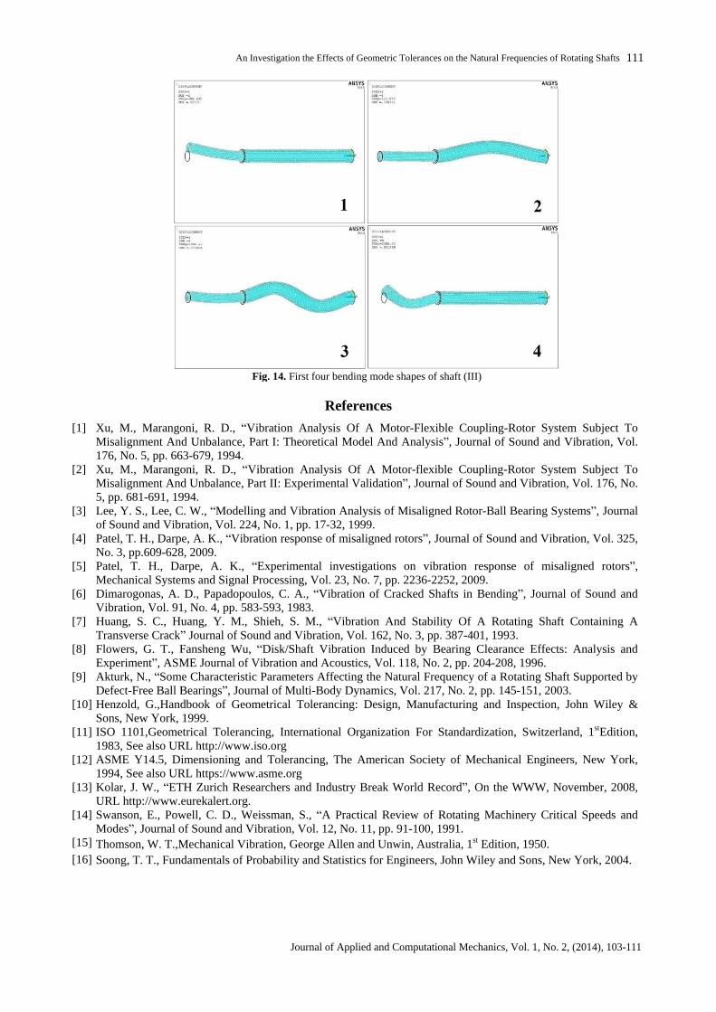
Vibrating mode shapes related to shafts (II) and (III) are shown in below:
Fig. 13. Mode shapes of shaft (II). Mode shapes 1, 2, 4 & 6 are first four bending vibrating modes. Mode shapes 3 & 5 are the torsional and longitudinal vibrating mode shapes respectively.
An Investigation the Effects of Geometric Tolerances on the Natural Frequencies of Rotating Shafts
Journal of Applied and Computational Mechanics, Vol. 1, No. 2, (2014), 103-111
111
Fig. 14. First four bending mode shapes of shaft (III)
References
Xu, M., Marangoni, R. D., Vibration Analysis Of A Motor-Flexible Coupling-Rotor System Subject ToMisalignment And Unbalance, Part I: Theoretical Model And Analysis , Journal of Sound and Vibration, Vol.176, No. 5, pp. 663-679, 1994.
[1]
Xu, M., Marangoni, R. D., Vibration Analysis Of A Motor-flexible Coupling-Rotor System Subject ToMisalignment And Unbalance, Part II: Experimental Validation , Journal of Sound and Vibration, Vol. 176, No. 5, pp. 681-691, 1994.
[2]
Lee, Y. S., Lee, C. W., Modelling and Vibration Analysis of Misaligned Rotor-Ball Bearing Systems , Journalof Sound and Vibration, Vol. 224, No. 1, pp. 17-32, 1999.
[3]
Patel, T. H., Darpe, A. K., Vibration response of misaligned rotors , Journal of Sound and Vibration, Vol. 325,No. 3, pp.609-628, 2009.
[4]
Patel, T. H., Darpe, A. K., Experimental investigations on vibration response of misaligned rotors ,Mechanical Systems and Signal Processing, Vol. 23, No. 7, pp. 2236-2252, 2009.
[5]
Dimarogonas, A. D., Papadopoulos, C. A., Vibration of Cracked Shafts in Bending , Journal of Sound andVibration, Vol. 91, No. 4, pp. 583-593, 1983.
[6]
Huang, S. C., Huang, Y. M., Shieh, S. M., Vibration And Stability Of A Rotating Shaft Containing ATransverse Crack Journal of Sound and Vibration, Vol. 162, No. 3, pp. 387-401, 1993.
[7]
Flowers, G. T., Fansheng Wu, Disk/Shaft Vibration Induced by Bearing Clearance Effects: Analysis andExperiment , ASME Journal of Vibration and Acoustics, Vol. 118, No. 2, pp. 204-208, 1996.
[8]
Akturk, N., Some Characteristic Parameters Affecting the Natural Frequency of a Rotating Shaft Supported byDefect-Free Ball Bearings , Journal of Multi-Body Dynamics, Vol. 217, No. 2, pp. 145-151, 2003.
[9]
Henzold, G.,Handbook of Geometrical Tolerancing: Design, Manufacturing and Inspection, John Wiley &Sons, New York, 1999.
[10]
ISO 1101,Geometrical Tolerancing, International Organization For Standardization, Switzerland, 1stEdition,1983, See also URL http://www.iso.org
[11]
ASME Y14.5, Dimensioning and Tolerancing, The American Society of Mechanical Engineers, New York,1994, See also URL https://www.asme.org
[12]
Kolar, J. W., ETH Zurich Researchers and Industry Break World Record , On the WWW, November, 2008,URL http://www.eurekalert.org.
[13]
Swanson, E., Powell, C. D., Weissman, S., A Practical Review of Rotating Machinery Critical Speeds andModes , Journal of Sound and Vibration, Vol. 12, No. 11, pp. 91-100, 1991.
[14]
Thomson, W. T.,Mechanical Vibration, George Allen and Unwin, Australia, 1st Edition, 1950.[15]
Soong, T. T., Fundamentals of Probability and Statistics for Engineers, John Wiley and Sons, New York, 2004.[16]