An Intuitive Framework for Real-Time Freeform Modeling
5
An Intuitive Framework for Real-Time Freeform Modeling Mario Botsch Leif Kobbelt Computer Graphics Group RWTH Aachen University Abstract We present a freeform modeling framework for unstructured trian- gle meshes which is based on constraint shape optimization. The goal is to simplify the user interaction even for quite complex freeform or multiresolution modifications. The user first sets vari- ous boundary constraints to define a custom tailored (abstract) basis function which is adjusted to a given design task. The actual mod- ification is then controlled by moving one single 9-dof manipula- tor object. The technique can handle arbitrary support regions and piecewise boundary conditions with smoothness ranging continu- ously from C 0 to C 2 . To more naturally adapt the modification to the shape of the support region, the deformed surface can be tuned to bend with anisotropic stiffness. We are able to achieve real-time response in an interactive design session even for complex meshes by precomputing a set of scalar-valued basis functions that corre- spond to the degrees of freedom of the manipulator by which the user controls the modification. CR Categories: I.3.5 [Computer Graphics]: Computational Ge- ometry and Object Modeling—Physically based modeling; I.3.6 [Computer Graphics]: Methodology and Techniques—Interaction Techniques Keywords: surface editing, freeform design, user interaction 1 Introduction Computer aided geometric design techniques have become an im- portant key technology in the industrial design and development process. The availability of digital 3D models during the various stages of the design process triggers a large number of applications ranging from numerical simulation and assembly planning to de- sign studies and product presentation. This variety of applications implies that there are many different (and sometimes contradict- ing) requirements for how these 3D models have to be accessed in an interactive design session. Especially in the earlier (concep- tual) design stages, the major bottleneck is still the freeform design metaphor which should allow the user to convey an imaginary shape to the computer system in an intuitive fashion. The fundamental problem here is that the space of possible geomet- ric shapes is extremely high dimensional and has a very complex structure with esthetically pleasing shapes sometimes lying surpris- ingly close to unacceptable shapes. The designer has to explore this rich space of shapes by just pressing buttons or clicking and drag- ging 2D positions on the screen. More sophisticated interaction technology like haptic input devices, immersive displays [Schkolne et al. 2001], or two-handed input metaphors [Llamas et al. 2003] are available today but they did not replace the well-established PC- based working place as it can be found in every industrial design company. In an interactive design session, the user usually drags control ver- tices which have three degrees of freedom (translation) or he moves more general manipulator objects having six (translation and rota- tion) or nine (plus scaling) degrees of freedom. For complex shape modifications several control handles have to be dragged sequen- tially or simultaneously. This rudimentary interface is the reason why it takes highly skilled experts to operate a CAD system. Never- theless it is the widely accepted standard and implemented in many NURBS or subdivision based modeling frameworks. Let S be the given shape that the designer wants to modify into another shape S 0 and let us assume that S and S 0 do not differ too much. Obviously, every extreme modification can be decomposed into a sequence of smaller modifications and this is what designers usually do – even traditional designers working with real clay, not just CAD designers. If we accept that interactive design is about dragging manipulators and verifying the result by visual feedback then any shape modifi- cation can be characterized by S 0 = S + B (δ C) (1) where B represents an abstract basis function and δ C somehow rep- resents the change of position and orientation of the control handles. For a modeling tool based on NURBS surfaces, e.g., B could be the set of tensor-product basis functions and δ C the displacement vec- tors by which we shift the corresponding control vertices. A shape modification is complex if the update B (δ C) is complex. This can be achieved by either providing a complicated handle ob- ject with many degrees of freedom or by using special basis func- tions that are adapted to the desired modification. Since our goal is to keep the user interaction simple, the possible types of modifi- cations that we can apply to the object S are hence limited by the abstract basis functions that our system associates with the control handles. In the case of NURBS or subdivision surfaces, this means that with each elementary modification we can add a smooth bump with rect- angular or polygonal support to the surface. Every more sophis- ticated modeling operation has to be built from these elementary modifications. An important limitation with most of the existing modeling frame- works is that the underlying mathematical surface representation is tightly linked to the type and number of control handles. This prob- lem is more than obvious if our geometry representation is based on unstructured triangle meshes since here, shifting a (control) ver- tex just adds a tiny hat function to the surface. In order to perform some non-trivial modification one has to manually move a larger number of control vertices simultaneously. In the setting of (1) this would correspond to a highly complex δ C, i.e. a highly complex user interaction.
Transcript of An Intuitive Framework for Real-Time Freeform Modeling
An Intuitive Framework for Real-Time Freeform Modeling
Mario Botsch Leif Kobbelt
Computer Graphics GroupRWTH Aachen University
Abstract
We present a freeform modeling framework for unstructured trian-gle meshes which is based on constraint shape optimization. Thegoal is to simplify the user interaction even for quite complexfreeform or multiresolution modifications. The user first sets vari-ous boundary constraints to define a custom tailored (abstract) basisfunction which is adjusted to a given design task. The actual mod-ification is then controlled by moving one single 9-dof manipula-tor object. The technique can handle arbitrary support regions andpiecewise boundary conditions with smoothness ranging continu-ously from C0 to C2. To more naturally adapt the modification tothe shape of the support region, the deformed surface can be tunedto bend with anisotropic stiffness. We are able to achieve real-timeresponse in an interactive design session even for complex meshesby precomputing a set of scalar-valued basis functions that corre-spond to the degrees of freedom of the manipulator by which theuser controls the modification.
CR Categories: I.3.5 [Computer Graphics]: Computational Ge-ometry and Object Modeling—Physically based modeling; I.3.6[Computer Graphics]: Methodology and Techniques—InteractionTechniques
Keywords: surface editing, freeform design, user interaction
1 Introduction
Computer aided geometric design techniques have become an im-portant key technology in the industrial design and developmentprocess. The availability of digital 3D models during the variousstages of the design process triggers a large number of applicationsranging from numerical simulation and assembly planning to de-sign studies and product presentation. This variety of applicationsimplies that there are many different (and sometimes contradict-ing) requirements for how these 3D models have to be accessedin an interactive design session. Especially in the earlier (concep-tual) design stages, the major bottleneck is still the freeform designmetaphor which should allow the user to convey an imaginary shapeto the computer system in an intuitive fashion.
The fundamental problem here is that the space of possible geomet-ric shapes is extremely high dimensional and has a very complexstructure with esthetically pleasing shapes sometimes lying surpris-ingly close to unacceptable shapes. The designer has to explore thisrich space of shapes by just pressing buttons or clicking and drag-ging 2D positions on the screen. More sophisticated interaction
technology like haptic input devices, immersive displays [Schkolneet al. 2001], or two-handed input metaphors [Llamas et al. 2003] areavailable today but they did not replace the well-established PC-based working place as it can be found in every industrial designcompany.
In an interactive design session, the user usually drags control ver-tices which have three degrees of freedom (translation) or he movesmore general manipulator objects having six (translation and rota-tion) or nine (plus scaling) degrees of freedom. For complex shapemodifications several control handles have to be dragged sequen-tially or simultaneously. This rudimentary interface is the reasonwhy it takes highly skilled experts to operate a CAD system. Never-theless it is the widely accepted standard and implemented in manyNURBS or subdivision based modeling frameworks.
Let S be the given shape that the designer wants to modify intoanother shape S′ and let us assume that S and S′ do not differ toomuch. Obviously, every extreme modification can be decomposedinto a sequence of smaller modifications and this is what designersusually do – even traditional designers working with real clay, notjust CAD designers.
If we accept that interactive design is about dragging manipulatorsand verifying the result by visual feedback then any shape modifi-cation can be characterized by
S′ = S +B(δC) (1)
where B represents an abstract basis function and δC somehow rep-resents the change of position and orientation of the control handles.For a modeling tool based on NURBS surfaces, e.g., B could be theset of tensor-product basis functions and δC the displacement vec-tors by which we shift the corresponding control vertices.
A shape modification is complex if the update B(δC) is complex.This can be achieved by either providing a complicated handle ob-ject with many degrees of freedom or by using special basis func-tions that are adapted to the desired modification. Since our goalis to keep the user interaction simple, the possible types of modifi-cations that we can apply to the object S are hence limited by theabstract basis functions that our system associates with the controlhandles.
In the case of NURBS or subdivision surfaces, this means that witheach elementary modification we can add a smooth bump with rect-angular or polygonal support to the surface. Every more sophis-ticated modeling operation has to be built from these elementarymodifications.
An important limitation with most of the existing modeling frame-works is that the underlying mathematical surface representation istightly linked to the type and number of control handles. This prob-lem is more than obvious if our geometry representation is basedon unstructured triangle meshes since here, shifting a (control) ver-tex just adds a tiny hat function to the surface. In order to performsome non-trivial modification one has to manually move a largernumber of control vertices simultaneously. In the setting of (1) thiswould correspond to a highly complex δC, i.e. a highly complexuser interaction.
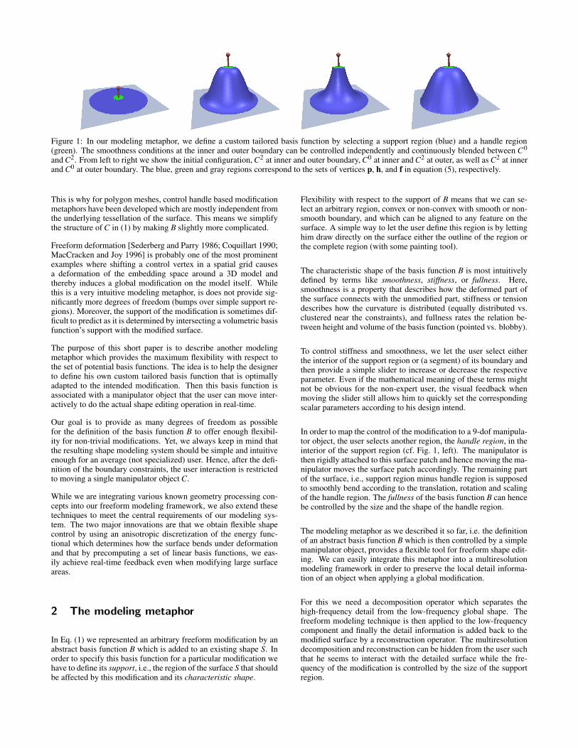
Figure 1: In our modeling metaphor, we define a custom tailored basis function by selecting a support region (blue) and a handle region(green). The smoothness conditions at the inner and outer boundary can be controlled independently and continuously blended between C0
and C2. From left to right we show the initial configuration, C2 at inner and outer boundary, C0 at inner and C2 at outer, as well as C2 at innerand C0 at outer boundary. The blue, green and gray regions correspond to the sets of vertices p, h, and f in equation (5), respectively.
This is why for polygon meshes, control handle based modificationmetaphors have been developed which are mostly independent fromthe underlying tessellation of the surface. This means we simplifythe structure of C in (1) by making B slightly more complicated.
Freeform deformation [Sederberg and Parry 1986; Coquillart 1990;MacCracken and Joy 1996] is probably one of the most prominentexamples where shifting a control vertex in a spatial grid causesa deformation of the embedding space around a 3D model andthereby induces a global modification on the model itself. Whilethis is a very intuitive modeling metaphor, is does not provide sig-nificantly more degrees of freedom (bumps over simple support re-gions). Moreover, the support of the modification is sometimes dif-ficult to predict as it is determined by intersecting a volumetric basisfunction’s support with the modified surface.
The purpose of this short paper is to describe another modelingmetaphor which provides the maximum flexibility with respect tothe set of potential basis functions. The idea is to help the designerto define his own custom tailored basis function that is optimallyadapted to the intended modification. Then this basis function isassociated with a manipulator object that the user can move inter-actively to do the actual shape editing operation in real-time.
Our goal is to provide as many degrees of freedom as possiblefor the definition of the basis function B to offer enough flexibil-ity for non-trivial modifications. Yet, we always keep in mind thatthe resulting shape modeling system should be simple and intuitiveenough for an average (not specialized) user. Hence, after the defi-nition of the boundary constraints, the user interaction is restrictedto moving a single manipulator object C.
While we are integrating various known geometry processing con-cepts into our freeform modeling framework, we also extend thesetechniques to meet the central requirements of our modeling sys-tem. The two major innovations are that we obtain flexible shapecontrol by using an anisotropic discretization of the energy func-tional which determines how the surface bends under deformationand that by precomputing a set of linear basis functions, we eas-ily achieve real-time feedback even when modifying large surfaceareas.
2 The modeling metaphor
In Eq. (1) we represented an arbitrary freeform modification by anabstract basis function B which is added to an existing shape S. Inorder to specify this basis function for a particular modification wehave to define its support, i.e., the region of the surface S that shouldbe affected by this modification and its characteristic shape.
Flexibility with respect to the support of B means that we can se-lect an arbitrary region, convex or non-convex with smooth or non-smooth boundary, and which can be aligned to any feature on thesurface. A simple way to let the user define this region is by lettinghim draw directly on the surface either the outline of the region orthe complete region (with some painting tool).
The characteristic shape of the basis function B is most intuitivelydefined by terms like smoothness, stiffness, or fullness. Here,smoothness is a property that describes how the deformed part ofthe surface connects with the unmodified part, stiffness or tensiondescribes how the curvature is distributed (equally distributed vs.clustered near the constraints), and fullness rates the relation be-tween height and volume of the basis function (pointed vs. blobby).
To control stiffness and smoothness, we let the user select eitherthe interior of the support region or (a segment) of its boundary andthen provide a simple slider to increase or decrease the respectiveparameter. Even if the mathematical meaning of these terms mightnot be obvious for the non-expert user, the visual feedback whenmoving the slider still allows him to quickly set the correspondingscalar parameters according to his design intend.
In order to map the control of the modification to a 9-dof manipula-tor object, the user selects another region, the handle region, in theinterior of the support region (cf. Fig. 1, left). The manipulator isthen rigidly attached to this surface patch and hence moving the ma-nipulator moves the surface patch accordingly. The remaining partof the surface, i.e., support region minus handle region is supposedto smoothly bend according to the translation, rotation and scalingof the handle region. The fullness of the basis function B can hencebe controlled by the size and the shape of the handle region.
The modeling metaphor as we described it so far, i.e. the definitionof an abstract basis function B which is then controlled by a simplemanipulator object, provides a flexible tool for freeform shape edit-ing. We can easily integrate this metaphor into a multiresolutionmodeling framework in order to preserve the local detail informa-tion of an object when applying a global modification.
For this we need a decomposition operator which separates thehigh-frequency detail from the low-frequency global shape. Thefreeform modeling technique is then applied to the low-frequencycomponent and finally the detail information is added back to themodified surface by a reconstruction operator. The multiresolutiondecomposition and reconstruction can be hidden from the user suchthat he seems to interact with the detailed surface while the fre-quency of the modification is controlled by the size of the supportregion.
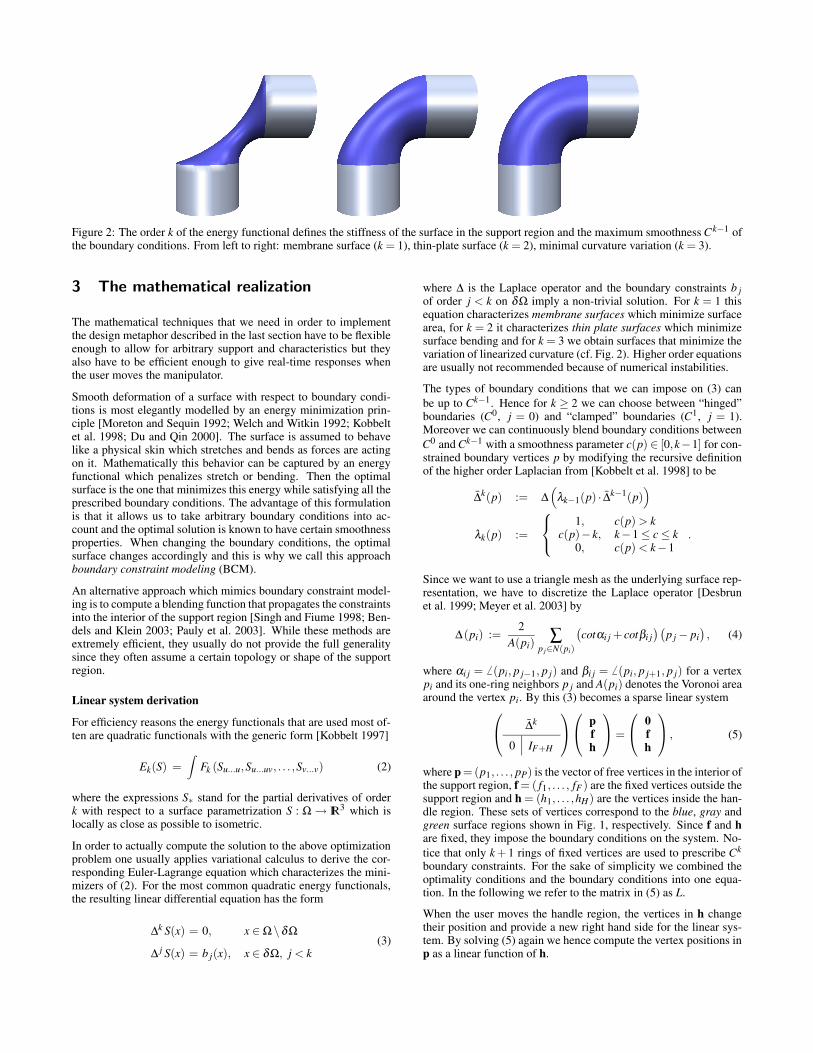
Figure 2: The order k of the energy functional defines the stiffness of the surface in the support region and the maximum smoothness Ck−1 ofthe boundary conditions. From left to right: membrane surface (k = 1), thin-plate surface (k = 2), minimal curvature variation (k = 3).
3 The mathematical realization
The mathematical techniques that we need in order to implementthe design metaphor described in the last section have to be flexibleenough to allow for arbitrary support and characteristics but theyalso have to be efficient enough to give real-time responses whenthe user moves the manipulator.
Smooth deformation of a surface with respect to boundary condi-tions is most elegantly modelled by an energy minimization prin-ciple [Moreton and Sequin 1992; Welch and Witkin 1992; Kobbeltet al. 1998; Du and Qin 2000]. The surface is assumed to behavelike a physical skin which stretches and bends as forces are actingon it. Mathematically this behavior can be captured by an energyfunctional which penalizes stretch or bending. Then the optimalsurface is the one that minimizes this energy while satisfying all theprescribed boundary conditions. The advantage of this formulationis that it allows us to take arbitrary boundary conditions into ac-count and the optimal solution is known to have certain smoothnessproperties. When changing the boundary conditions, the optimalsurface changes accordingly and this is why we call this approachboundary constraint modeling (BCM).
An alternative approach which mimics boundary constraint model-ing is to compute a blending function that propagates the constraintsinto the interior of the support region [Singh and Fiume 1998; Ben-dels and Klein 2003; Pauly et al. 2003]. While these methods areextremely efficient, they usually do not provide the full generalitysince they often assume a certain topology or shape of the supportregion.
Linear system derivation
For efficiency reasons the energy functionals that are used most of-ten are quadratic functionals with the generic form [Kobbelt 1997]
Ek(S) =∫
Fk (Su...u,Su...uv, . . . ,Sv...v) (2)
where the expressions S∗ stand for the partial derivatives of orderk with respect to a surface parametrization S : Ω → IR3 which islocally as close as possible to isometric.
In order to actually compute the solution to the above optimizationproblem one usually applies variational calculus to derive the cor-responding Euler-Lagrange equation which characterizes the mini-mizers of (2). For the most common quadratic energy functionals,the resulting linear differential equation has the form
∆k S(x) = 0, x ∈ Ω\δΩ
∆ j S(x) = b j(x), x ∈ δΩ, j < k(3)
where ∆ is the Laplace operator and the boundary constraints b jof order j < k on δΩ imply a non-trivial solution. For k = 1 thisequation characterizes membrane surfaces which minimize surfacearea, for k = 2 it characterizes thin plate surfaces which minimizesurface bending and for k = 3 we obtain surfaces that minimize thevariation of linearized curvature (cf. Fig. 2). Higher order equationsare usually not recommended because of numerical instabilities.
The types of boundary conditions that we can impose on (3) canbe up to Ck−1. Hence for k ≥ 2 we can choose between “hinged”boundaries (C0, j = 0) and “clamped” boundaries (C1, j = 1).Moreover we can continuously blend boundary conditions betweenC0 and Ck−1 with a smoothness parameter c(p) ∈ [0,k−1] for con-strained boundary vertices p by modifying the recursive definitionof the higher order Laplacian from [Kobbelt et al. 1998] to be
∆k(p) := ∆(
λk−1(p) · ∆k−1(p))
λk(p) :=
1, c(p) > kc(p)− k, k−1 ≤ c ≤ k
0, c(p) < k−1.
Since we want to use a triangle mesh as the underlying surface rep-resentation, we have to discretize the Laplace operator [Desbrunet al. 1999; Meyer et al. 2003] by
∆(pi) :=2
A(pi)∑
p j∈N(pi)
(
cotαi j + cotβi j)(
p j − pi)
, (4)
where αi j = 6 (pi, p j−1, p j) and βi j = 6 (pi, p j+1, p j) for a vertexpi and its one-ring neighbors p j and A(pi) denotes the Voronoi areaaround the vertex pi. By this (3) becomes a sparse linear system
∆k
0 IF+H
pfh
=
0fh
, (5)
where p = (p1, . . . , pP) is the vector of free vertices in the interior ofthe support region, f = ( f1, . . . , fF ) are the fixed vertices outside thesupport region and h = (h1, . . . ,hH) are the vertices inside the han-dle region. These sets of vertices correspond to the blue, gray andgreen surface regions shown in Fig. 1, respectively. Since f and hare fixed, they impose the boundary conditions on the system. No-tice that only k + 1 rings of fixed vertices are used to prescribe Ck
boundary constraints. For the sake of simplicity we combined theoptimality conditions and the boundary conditions into one equa-tion. In the following we refer to the matrix in (5) as L.
When the user moves the handle region, the vertices in h changetheir position and provide a new right hand side for the linear sys-tem. By solving (5) again we hence compute the vertex positions inp as a linear function of h.
Anisotropic bending
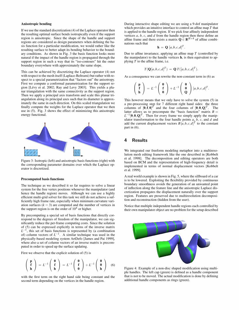
If we use the standard discretization (4) of the Laplace operator thenthe resulting optimal surface bends isotropically even if the supportregion is anisotropic. Since the shape of the handle and supportregions are considered as design parameters when defining the ba-sis function for a particular modification, we would rather like theresulting surface to better adapt its bending behavior to the bound-ary conditions. As shown in Fig. 3 the basis function looks morenatural if the impact of the handle region is propagated through thesupport region in such a way that its “iso-contours” hit the outerboundary everywhere with approximately the same slope.
This can be achieved by discretizing the Laplace operator (4) notwith respect to the mesh itself (Laplace-Beltrami) but rather with re-spect to a special parametrization that “factors out” the anisotropy.First we compute a conformal parametrization for the support re-gion [Levy et al. 2002; Ray and Levy 2003]. This yields a pla-nar triangulation with the same connectivity as the support region.Then we apply a principal axis transform and scale this planar tri-angulation along its principal axes such that its diameter is approx-imately the same in each direction. On this scaled triangulation wefinally compute the weights for the Laplace operator that we thenuse in (5). Fig. 3 shows the effect of minimizing this anisotropicenergy functional.
Figure 3: Isotropic (left) and anisotropic basis functions (right) withthe corresponding parameter domains over which the Laplace op-erator is discretized.
Precomputed basis functions
The technique as we described it so far requires to solve a linearsystem for the free vertex positions whenever the manipulator (andhence the handle region) moves. Although we can use a highlyefficient multi-grid solver for this task we still do not achieve a suf-ficiently high frame rate, especially when minimum curvature vari-ation surfaces (k = 3) are computed and the number of vertices inthe support region is on the order of 104 or higher.
By precomputing a special set of basis functions that directly cor-respond to the degrees of freedom of the manipulator, we can sig-nificantly reduce the per-frame computing costs. Since the solutionof (5) can be expressed explicitly in terms of the inverse matrixL−1, this set of basis functions is represented by (a combinationof) column vectors of L−1. A similar technique was used in thephysically-based modeling system ArtDefo [James and Pai 1999],where also a set of column vectors of an inverse matrix is precom-puted in order to speed up the surface updating.
First we observe that the explicit solution of (5) is
pfh
= L−1
0fh
= L−1
0f0
+ L−1
00h
(6)
with the first term on the right hand side being constant and thesecond term depending on the vertices in the handle region.
During interactive shape editing we are using a 9-dof manipulatorwhich provides an intuitive interface to control an affine map T thatis applied to the handle region. If we pick four affinely independentvertices a, b, c, and d from the handle region then these define anaffine frame and there exists a matrix Q ∈ IRH×4 of affine combi-nations such that
h = Q [a,b,c,d]T .
Due to affine invariance, applying an affine map T (controlled bythe manipulator) to the handle vertices h, is then equivalent to ap-plying T to the affine frame, i.e.
T (Q [a,b,c,d]T ) = Q T ([a,b,c,d]T ).
As a consequence we can rewrite the non-constant term in (6) as
pfh
= L−1
0f0
+ L−1
00Q
[a,b,c,d]T .
This however means that we only have to solve the system (5) ina pre-processing step for 7 different right hand sides: the threecolumns of [0, f,0]T and the four columns of [0,0,Q]T . Thelatter allows us to precompute the “basis function” matrix B =L−1[0,0,Q]T . Then for every frame we simply apply the manip-ulator transformation to the four handle points a, b, c, and d andadd the current displacement vectors B [a,b,c,d]T to the constantpart in (6).
4 Results
We integrated our freeform modeling metaphor into a multireso-lution mesh editing framework like the one described in [Kobbeltet al. 1998]. The decomposition and editing operators are bothbased on BCM and the representation of high-frequency detail isimplemented in terms of normal displacement vectors [Kobbeltet al. 1999].
A real world example is shown in Fig. 5, where the sillboard of a caris to be lowered. Exploiting the flexibility provided by continuousboundary smoothness avoids the generation of an unwanted pointof inflection along the feature line and the anisotropic Laplace dis-cretization propagates the displacement naturally over the supportregion. Features are preserved due to multiresolution decomposi-tion and reconstruction (hidden from the user).
Notice that multiple independent handle regions each controlled bytheir own manipulator object are no problem for the setup described
Figure 4: Example of a non-disc shaped modification using multi-ple handles. The left cap (green) is defined as a handle componentthat is not to be moved. The actual modification is done by definingadditional handle components as rings (green).
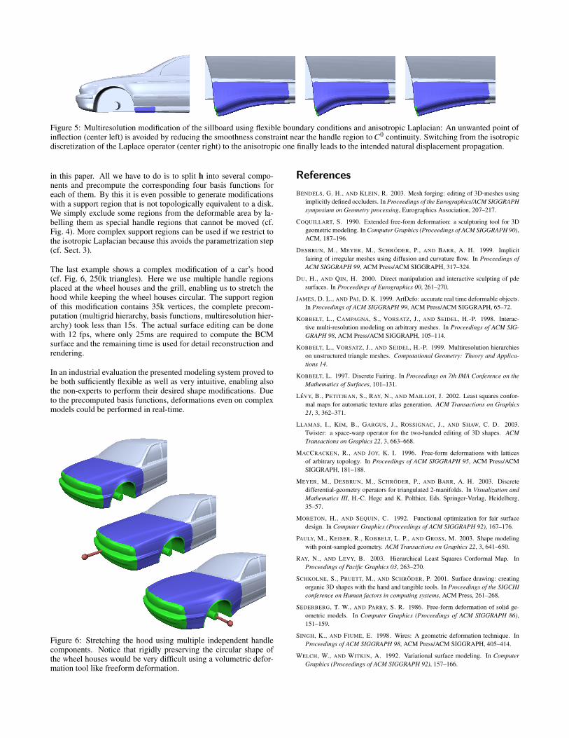
Figure 5: Multiresolution modification of the sillboard using flexible boundary conditions and anisotropic Laplacian: An unwanted point ofinflection (center left) is avoided by reducing the smoothness constraint near the handle region to C0 continuity. Switching from the isotropicdiscretization of the Laplace operator (center right) to the anisotropic one finally leads to the intended natural displacement propagation.
in this paper. All we have to do is to split h into several compo-nents and precompute the corresponding four basis functions foreach of them. By this it is even possible to generate modificationswith a support region that is not topologically equivalent to a disk.We simply exclude some regions from the deformable area by la-belling them as special handle regions that cannot be moved (cf.Fig. 4). More complex support regions can be used if we restrict tothe isotropic Laplacian because this avoids the parametrization step(cf. Sect. 3).
The last example shows a complex modification of a car’s hood(cf. Fig. 6, 250k triangles). Here we use multiple handle regionsplaced at the wheel houses and the grill, enabling us to stretch thehood while keeping the wheel houses circular. The support regionof this modification contains 35k vertices, the complete precom-putation (multigrid hierarchy, basis functions, multiresolution hier-archy) took less than 15s. The actual surface editing can be donewith 12 fps, where only 25ms are required to compute the BCMsurface and the remaining time is used for detail reconstruction andrendering.
In an industrial evaluation the presented modeling system proved tobe both sufficiently flexible as well as very intuitive, enabling alsothe non-experts to perform their desired shape modifications. Dueto the precomputed basis functions, deformations even on complexmodels could be performed in real-time.
Figure 6: Stretching the hood using multiple independent handlecomponents. Notice that rigidly preserving the circular shape ofthe wheel houses would be very difficult using a volumetric defor-mation tool like freeform deformation.
References
BENDELS, G. H., AND KLEIN, R. 2003. Mesh forging: editing of 3D-meshes usingimplicitly defined occluders. In Proceedings of the Eurographics/ACM SIGGRAPHsymposium on Geometry processing, Eurographics Association, 207–217.
COQUILLART, S. 1990. Extended free-form deformation: a sculpturing tool for 3Dgeometric modeling. In Computer Graphics (Proceedings of ACM SIGGRAPH 90),ACM, 187–196.
DESBRUN, M., MEYER, M., SCHRODER, P., AND BARR, A. H. 1999. Implicitfairing of irregular meshes using diffusion and curvature flow. In Proceedings ofACM SIGGRAPH 99, ACM Press/ACM SIGGRAPH, 317–324.
DU, H., AND QIN, H. 2000. Direct manipulation and interactive sculpting of pdesurfaces. In Proceedings of Eurographics 00, 261–270.
JAMES, D. L., AND PAI, D. K. 1999. ArtDefo: accurate real time deformable objects.In Proceedings of ACM SIGGRAPH 99, ACM Press/ACM SIGGRAPH, 65–72.
KOBBELT, L., CAMPAGNA, S., VORSATZ, J., AND SEIDEL, H.-P. 1998. Interac-tive multi-resolution modeling on arbitrary meshes. In Proceedings of ACM SIG-GRAPH 98, ACM Press/ACM SIGGRAPH, 105–114.
KOBBELT, L., VORSATZ, J., AND SEIDEL, H.-P. 1999. Multiresolution hierarchieson unstructured triangle meshes. Computational Geometry: Theory and Applica-tions 14.
KOBBELT, L. 1997. Discrete Fairing. In Proceedings on 7th IMA Conference on theMathematics of Surfaces, 101–131.
LEVY, B., PETITJEAN, S., RAY, N., AND MAILLOT, J. 2002. Least squares confor-mal maps for automatic texture atlas generation. ACM Transactions on Graphics21, 3, 362–371.
LLAMAS, I., KIM, B., GARGUS, J., ROSSIGNAC, J., AND SHAW, C. D. 2003.Twister: a space-warp operator for the two-handed editing of 3D shapes. ACMTransactions on Graphics 22, 3, 663–668.
MACCRACKEN, R., AND JOY, K. I. 1996. Free-form deformations with latticesof arbitrary topology. In Proceedings of ACM SIGGRAPH 95, ACM Press/ACMSIGGRAPH, 181–188.
MEYER, M., DESBRUN, M., SCHRODER, P., AND BARR, A. H. 2003. Discretedifferential-geometry operators for triangulated 2-manifolds. In Visualization andMathematics III, H.-C. Hege and K. Polthier, Eds. Springer-Verlag, Heidelberg,35–57.
MORETON, H., AND SEQUIN, C. 1992. Functional optimization for fair surfacedesign. In Computer Graphics (Proceedings of ACM SIGGRAPH 92), 167–176.
PAULY, M., KEISER, R., KOBBELT, L. P., AND GROSS, M. 2003. Shape modelingwith point-sampled geometry. ACM Transactions on Graphics 22, 3, 641–650.
RAY, N., AND LEVY, B. 2003. Hierarchical Least Squares Conformal Map. InProceedings of Pacific Graphics 03, 263–270.
SCHKOLNE, S., PRUETT, M., AND SCHRODER, P. 2001. Surface drawing: creatingorganic 3D shapes with the hand and tangible tools. In Proceedings of the SIGCHIconference on Human factors in computing systems, ACM Press, 261–268.
SEDERBERG, T. W., AND PARRY, S. R. 1986. Free-form deformation of solid ge-ometric models. In Computer Graphics (Proceedings of ACM SIGGRAPH 86),151–159.
SINGH, K., AND FIUME, E. 1998. Wires: A geometric deformation technique. InProceedings of ACM SIGGRAPH 98, ACM Press/ACM SIGGRAPH, 405–414.
WELCH, W., AND WITKIN, A. 1992. Variational surface modeling. In ComputerGraphics (Proceedings of ACM SIGGRAPH 92), 157–166.