
An introduction to Realistic Ocean Rendering through FFT - Fabio Suriano - Codemotion Rome 2017
48
An Introduction to Realistic Ocean Rendering through FFT
-
Upload
codemotion -
Category
Technology
-
view
174 -
download
20
Transcript of An introduction to Realistic Ocean Rendering through FFT - Fabio Suriano - Codemotion Rome 2017
An Introduction to Realistic Ocean Rendering throughFFT

FABIO SURIANO
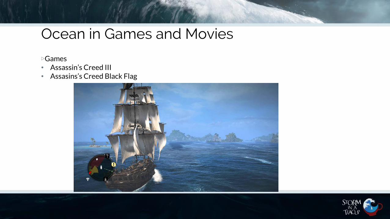
Ocean in Games and Movies
▷Games• Assassin’s Creed III• Assasins’s Creed Black Flag

Ocean in Games and Movies
▷Games
• Crysis
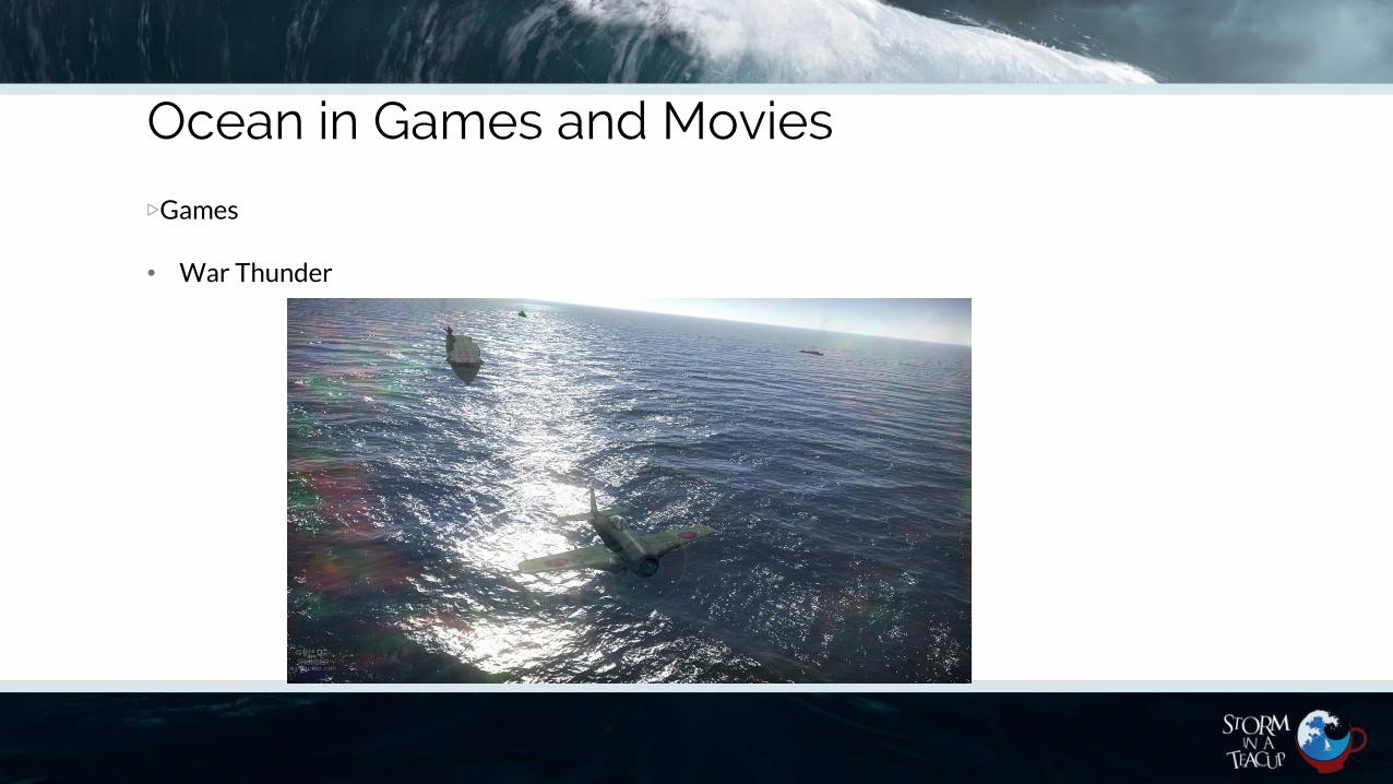
Ocean in Games and Movies
▷Games
• War Thunder
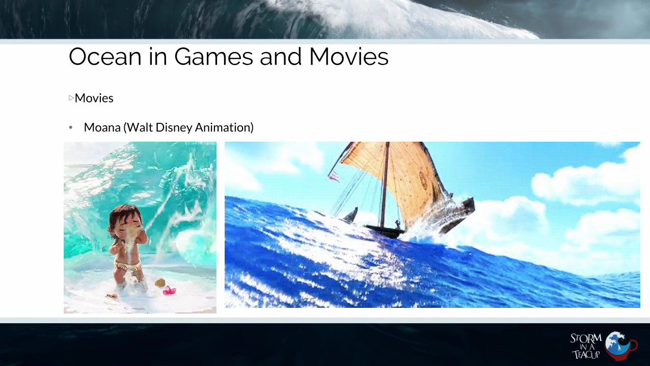
Ocean in Games and Movies
▷Movies
• Moana (Walt Disney Animation)

Ocean in Games and Movies
▷Movies
• Titanic
What they have in common ?
▷They all run an ocean simulation based on Fast Fourier Transform (FFT) (Simulating Ocean Water by Jerry Tessendorf [Tessendorf J. 2001])
▷The simulation takes as input a frequency domain spectrum representationand perfom the inverse of the Discrete Fourier Trasform (DFT) of thatspectrum
▷The result will be the time domain representation of the signal
▷The time domain representation is basically our heightmap at time t

Why FFT ?
▷Because computing the DFT as is, is expensive
▷DFT Complexity is for n samples
▷FFT (Fast fourier transform) has a complexity of
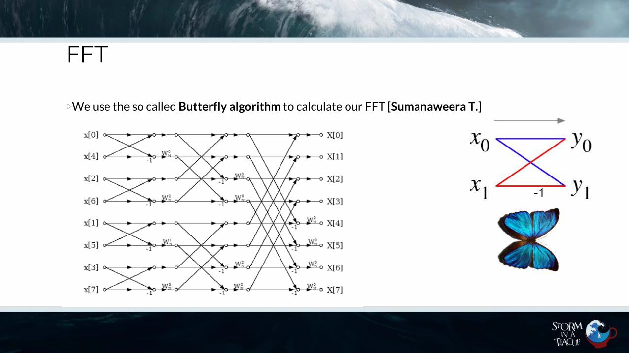
▷The FFT algorithm that we use is the so calledCooley–Tukey (or Butterfly) algorithm
How big should the Fourier grid be?
▷For many situations, values in the range 128 to 512 are sufficient [Tessendorf J. 2001].
▷Titanic and Waterworld were 2048x2048
▷Above a value of 2048, one should be careful because the limits of numerical accuracy for floating point calculations can become noticeable
▷We use a grid size of 512x512
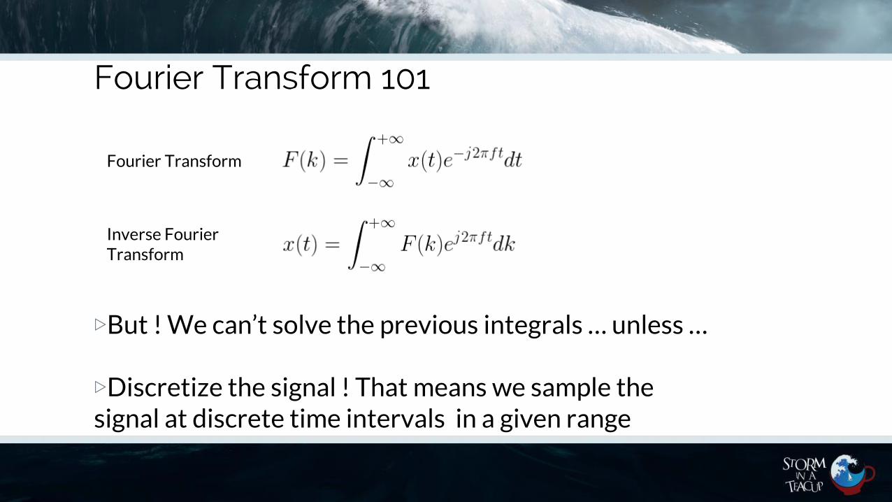
Fourier Transform 101
▷But ! We can’t solve the previous integrals … unless …
▷Discretize the signal ! That means we sample the signal at discrete time intervals in a given range
Inverse Fourier Transform
Fourier Transform
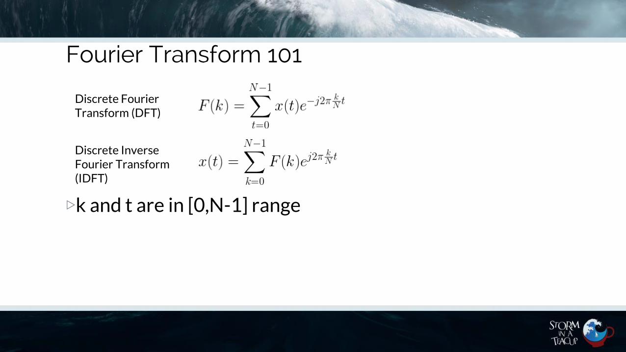
Fourier Transform 101
▷k and t are in [0,N-1] range
Discrete Inverse Fourier Transform(IDFT)
Discrete Fourier Transform (DFT)
FFT
▷We use the so called Butterfly algorithm to calculate our FFT [Sumanaweera T.]
FFT
▷Butterfly algorithm is quite complex
▷Normally you could find third party libraries that will perform FFT and inverse (IFFT) for you
▷I decided to implement a Radix-2 IFFT on my own on the Compute Shaderin order to transform our frequency spectrum to the time domain
▷Our ocean simulation is mostly implemented on compute shaders under Unreal Engine 4
▷We won’t go through the implementation details as you can find tons of information online on the butterfly algorithm itself
What’s the math(ter) ☺ ?
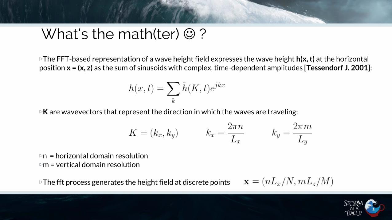
▷The FFT-based representation of a wave height field expresses the wave height h(x, t) at the horizontal position x = (x, z) as the sum of sinusoids with complex, time-dependent amplitudes [Tessendorf J. 2001]:
▷K are wavevectors that represent the direction in which the waves are traveling:
▷n = horizontal domain resolution▷m = vertical domain resolution
▷The fft process generates the height field at discrete points

What’s the math(ter) ☺ ?
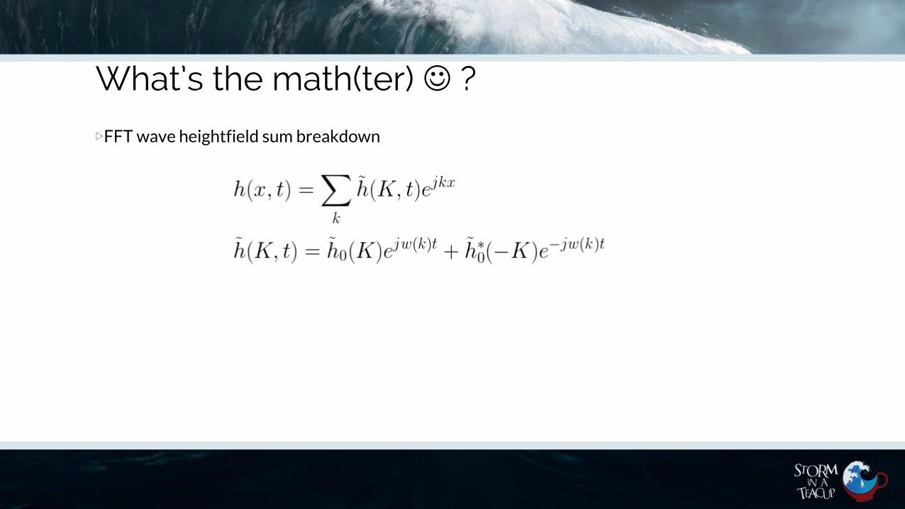
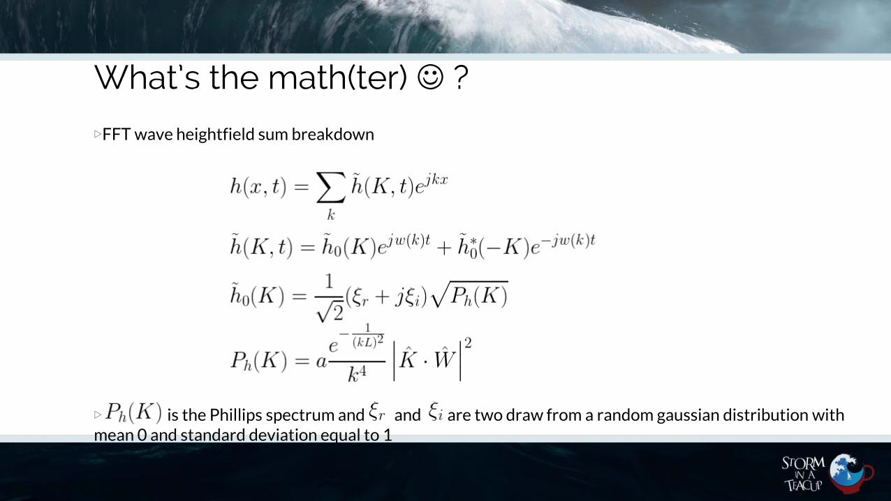
▷FFT wave heightfield sum breakdown
What’s the math(ter) ☺ ?
▷FFT wave heightfield sum breakdown

What’s the math(ter) ☺ ?
▷FFT wave heightfield sum breakdown

What’s the math(ter) ☺ ?
▷FFT wave heightfield sum breakdown
What’s the math(ter) ☺ ?
▷FFT wave heightfield sum breakdown
▷ is the Phillips spectrum and and are two draw from a random gaussian distribution with mean 0 and standard deviation equal to 1

What’s the math(ter) ☺ ?
▷Animating Waves: The Dispersion Relation
▷Relationship between the set of frequencies and the magnitude of their corrisponding wave vectors
▷Given the Euler formula we have
And therefore we can easily derive that

Phillips Spectrum
▷It’s a spectrum derived from empirical data based on the observation of the real sea
▷ : global wave amplitude▷ : normalized wave direction vector▷ : the magnitude of ▷ : normalized wind direction vector▷ : wind speed ▷ : gravitational constant

Normal and Displacement map
Height Map Normal Map
Central Difference▷
Normal and Displacement map
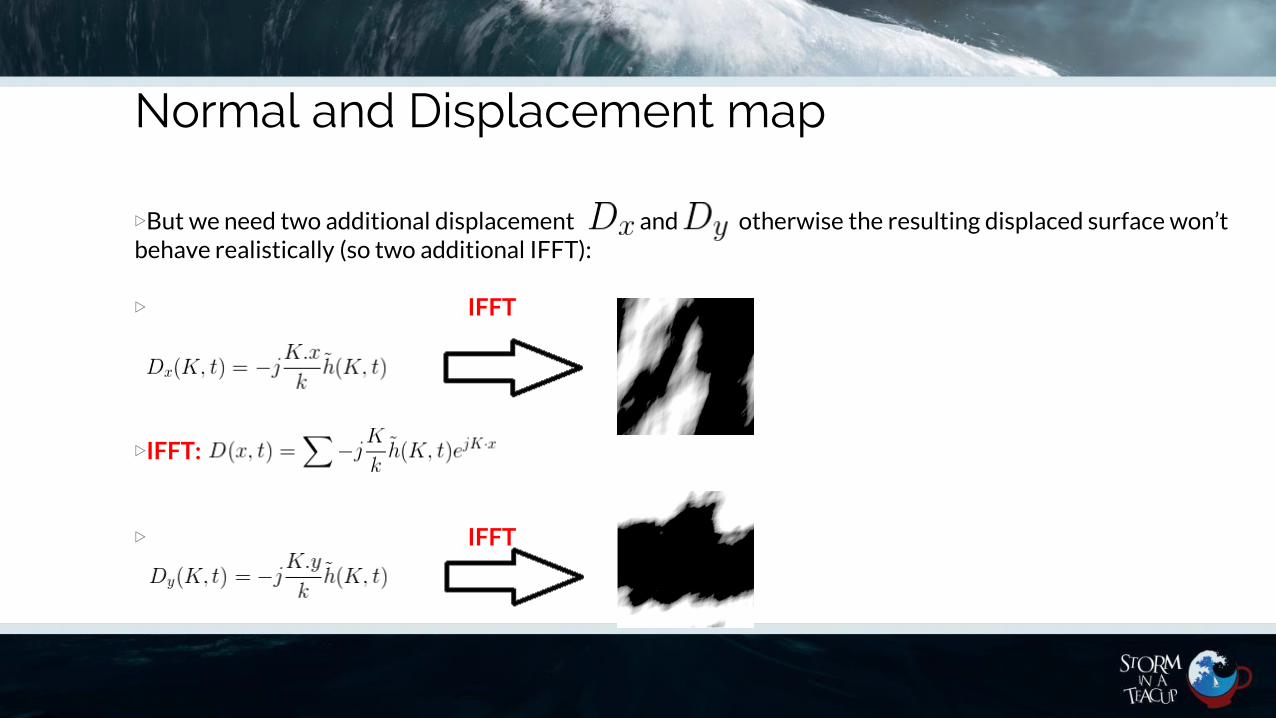
▷But we need two additional displacement and otherwise the resulting displaced surface won’tbehave realistically (so two additional IFFT):
▷ IFFT
▷IFFT:
▷ IFFT
Normal and Displacement map
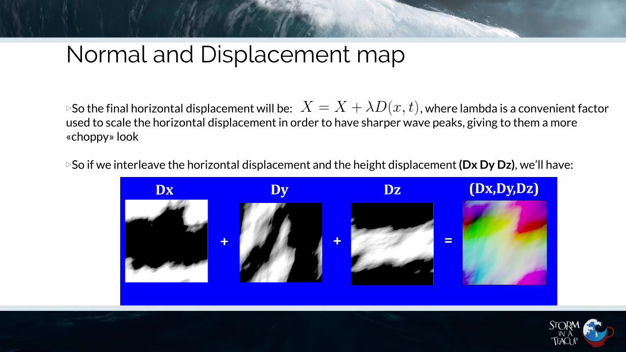
▷So the final horizontal displacement will be: , where lambda is a convenient factorused to scale the horizontal displacement in order to have sharper wave peaks, giving to them a more «choppy» look
▷So if we interleave the horizontal displacement and the height displacement (Dx Dy Dz), we’ll have:
Normal and displacement map
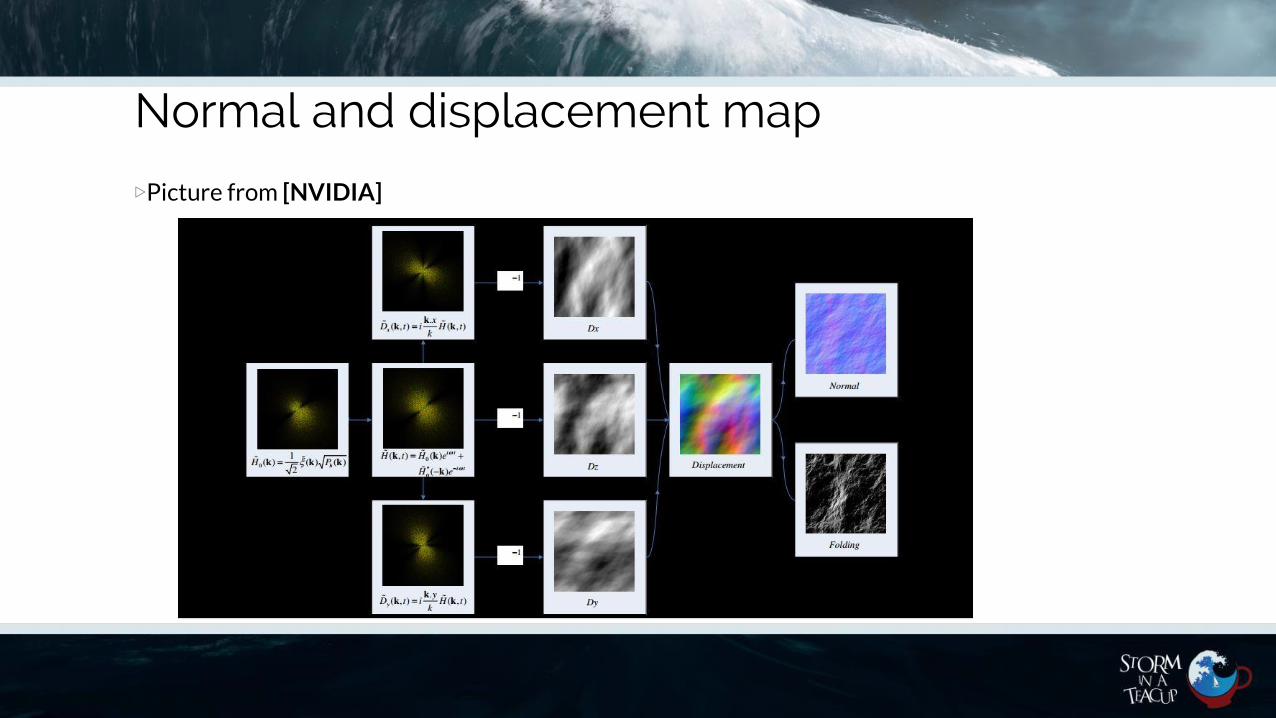
▷Picture from [NVIDIA]
Kenshiro is crying in this very moment …
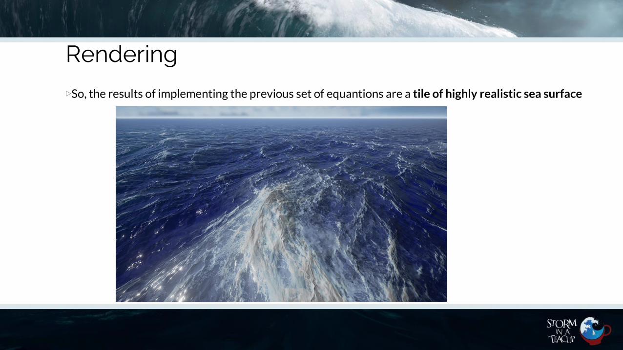
Rendering
▷So, the results of implementing the previous set of equantions are a tile of highly realistic sea surface

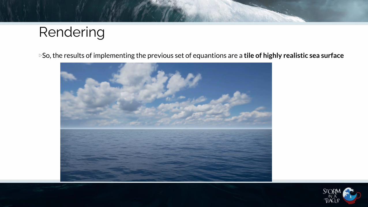
Rendering
▷So, the results of implementing the previous set of equantions are a tile of highly realistic sea surface

Rendering
▷So, the results of implementing the previous set of equantions are a tile of highly realistic sea surface

What about Ocean Foams ?
▷Ocean has Foams☺
▷
Foams happen on the tip/crest of a given wave

What about Ocean Foams ?
▷We can use the Jacobian [Tessendorf J. 2001] of our displacement map in order to calculate a convenientmap that will mask only the wave peaks:
Folding Map
*
We will call this map folding map because it represents were the wave peaks self intersect them until they fold on themselves
Rendering
▷So, the results of implementing the previous set of equantions are a tile of highly realistic sea surface
Ocean LOD
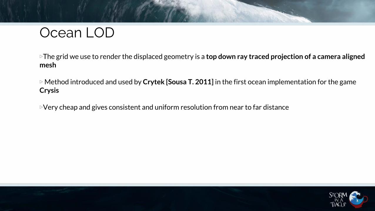
▷The grid we use to render the displaced geometry is a top down ray traced projection of a camera alignedmesh

Ocean LOD
▷The grid we use to render the displaced geometry is a top down ray traced projection of a camera alignedmesh
▷Method introduced and used by Crytek [Sousa T. 2011] in the first ocean implementation for the game Crysis
Ocean LOD
▷The grid we use to render the displaced geometry is a top down ray traced projection of a camera alignedmesh
▷Method introduced and used by Crytek [Sousa T. 2011] in the first ocean implementation for the game Crysis
▷Very cheap and gives consistent and uniform resolution from near to far distance
Ocean LOD
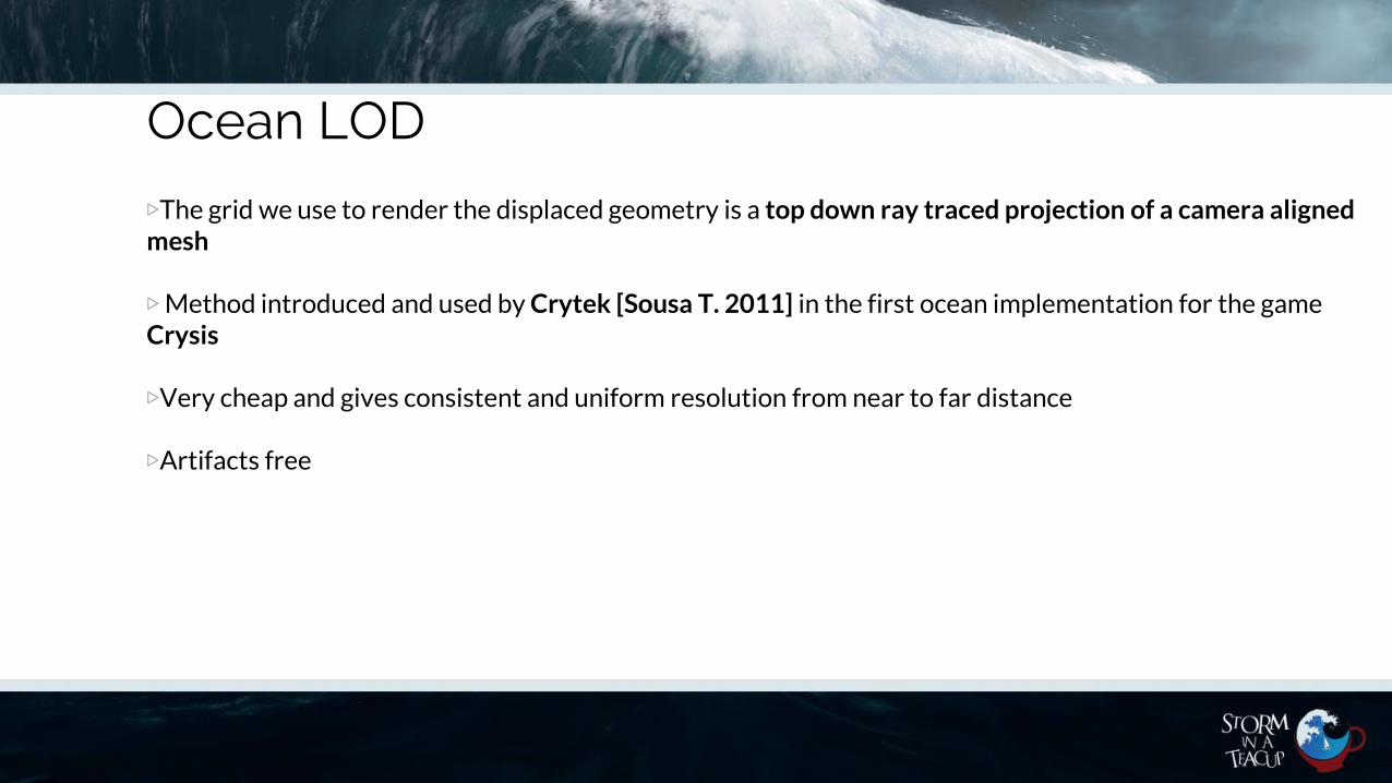
▷The grid we use to render the displaced geometry is a top down ray traced projection of a camera alignedmesh
▷Method introduced and used by Crytek [Sousa T. 2011] in the first ocean implementation for the game Crysis
▷Very cheap and gives consistent and uniform resolution from near to far distance
▷Artifacts free

Ocean LOD
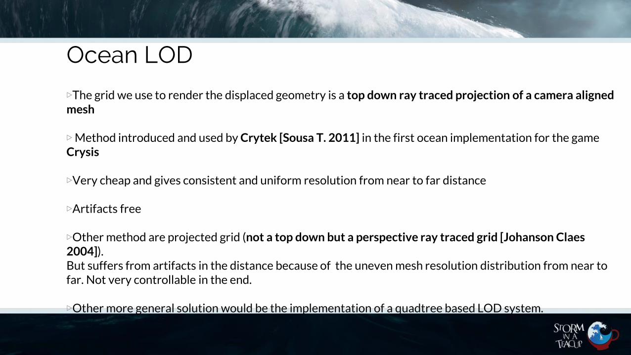
▷The grid we use to render the displaced geometry is a top down ray traced projection of a camera alignedmesh
▷Method introduced and used by Crytek [Sousa T. 2011] in the first ocean implementation for the game Crysis
▷Very cheap and gives consistent and uniform resolution from near to far distance
▷Artifacts free
▷Other method are projected grid (not a top down but a perspective ray traced grid [Johanson Claes2004]). But suffers from artifacts in the distance because of the uneven mesh resolution distribution from near to far. Not very controllable in the end.
Ocean LOD
▷The grid we use to render the displaced geometry is a top down ray traced projection of a camera alignedmesh
▷Method introduced and used by Crytek [Sousa T. 2011] in the first ocean implementation for the game Crysis
▷Very cheap and gives consistent and uniform resolution from near to far distance
▷Artifacts free
▷Other method are projected grid (not a top down but a perspective ray traced grid [Johanson Claes2004]). But suffers from artifacts in the distance because of the uneven mesh resolution distribution from near to far. Not very controllable in the end.
▷Other more general solution would be the implementation of a quadtree based LOD system.

Ocean level of detail (LOD)
▷The grid used to render the displaced geometry is a top down projection of a camera aligned mesh
▷ Player Camera point of view (POV)
Ocean LOD
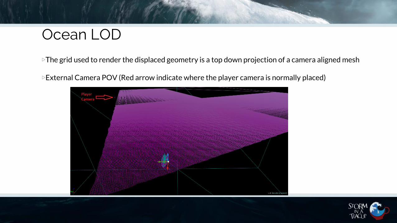
▷The grid used to render the displaced geometry is a top down projection of a camera aligned mesh
▷External Camera POV (Red arrow indicate where the player camera is normally placed)
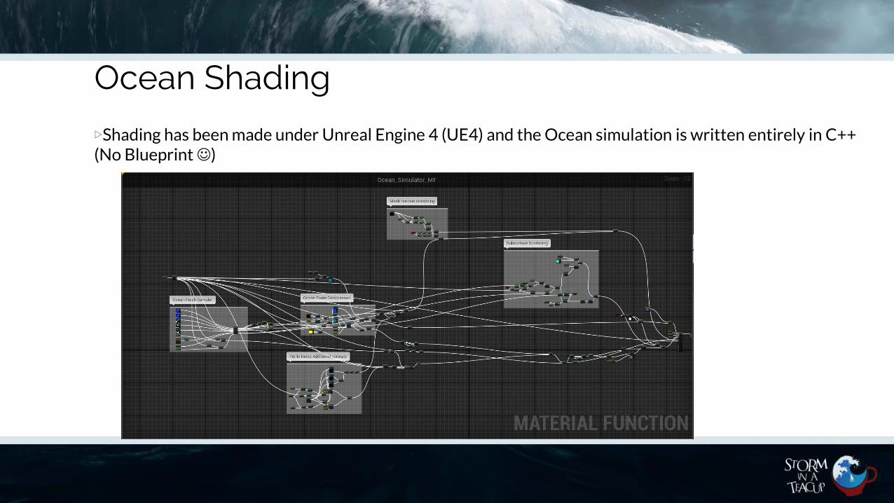
Ocean Shading
▷Shading has been made under Unreal Engine 4 (UE4) and the Ocean simulation is written entirely in C++ (No Blueprint☺)

Ocean Shading
▷Water in general is rendered by a minimum of two main shading aspects:
• Reflection• Refraction
The Fresnel term will state the probability for a ray to be reflected
See the complete Fresnel expression below only for the vertical polarization:
So we normally won’t use the previous expression because it’s expensive
We use then the Schlick Fresnel approximation [Schilck C. 1994]
Ocean Shading
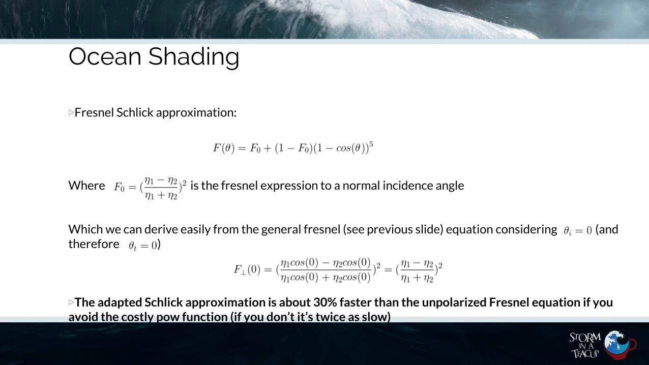
▷Fresnel Schlick approximation:
Where is the fresnel expression to a normal incidence angle
Which we can derive easily from the general fresnel (see previous slide) equation considering (and therefore )
▷The adapted Schlick approximation is about 30% faster than the unpolarized Fresnel equation if you avoid the costly pow function (if you don’t it’s twice as slow)

Ocean Shading
▷Because by the definition Fresnel (F) is a probability function, we know that will be in [0,1] range
▷Therefore our final reflected/refracted Ocean color will be
FinalColor = lerp(WaterColor,EnvMapColor,F)
▷Where F is our fresnel computed with the Schlick approximation [Schlick C. 1994]
▷When it comes to UE4 we also have the chance to add screen space reflections that will give us an additional occlusion for the ambient reflection that EnvMap can’t

Questions ?

References
[Tessendorf J. 2001]: Simulating ocean water. In ACM SIGGRAPH course notes (2001).
[Golias R., Jensen L.S.]: Deep Water Animation and Rendering. Gamasutra.com
[Schlick C. 1994]: An inexpensive BRDF model for physically-based rendering. Computer Graphics Forum 13 (1994), 233–246.
[Seymour M. 2012]: Assassin’s Creed III: The tech behind (or beneath) the action. FxGuide
[Sumanaweera T.]: Medical Image Reconstruction with the FFT. GPU Gems 2, Chapter 48
[NVIDIA]: Ocean Surface Simulation
[Sousa T. 2011]: CryENGINE 3 Rendering Techniques. Gamefest 2011
[Johanson Claes 2004]: Real-time water rendering - introducing the projected grid concept. Master of Science thesis in computer graphics

Thanks for your time!
Contacts:
Senior Graphics Programmer [email protected]
PR & Marketing [email protected]
Information [email protected]