An Introduction to Mixed-Signal IC Test and Measurement · · 2007-05-11An Introduction to...
13
An Introduction to Mixed-Signal IC Test and Measurement Mark Burns Texas Instruments, Incorporated Gordon W. Roberts McGill University New York Oxford OXFORD UNIVERSITY PRESS 2001
-
Upload
truongkhuong -
Category
Documents
-
view
223 -
download
1
Transcript of An Introduction to Mixed-Signal IC Test and Measurement · · 2007-05-11An Introduction to...
An Introduction to
Mixed-Signal IC Test and Measurement
Mark BurnsTexas Instruments, Incorporated
Gordon W. RobertsMcGill University
New York Oxford
OXFORD UNIVERSITY PRESS
2001
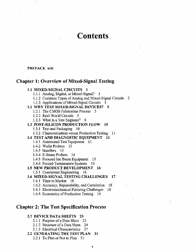
Contents
PREFACE xvii
Chapter 1: Overview of Mixed-Signal Testing
1.1 MIXED-SIGNAL CIRCUITS 11.1.1 Analog, Digital, or Mixed-Signal? 11.1.2 Common Types of Analog and Mixed-Signal Circuits1.1.3 Applications of Mixed-Signal Circuits 3
1.2 WHY TEST MIXED-SIGNAL DEVICES? 51.2.1 The CMOS Fabrication Process 51.2.2 Real-World Circuits 51.2.3 What Is a Test Engineer? 8
1.3 POST-SILICON PRODUCTION FLOW 101.3.1 Test and Packaging 101.3.2 Characterization versus Production Testing 11
1.4 TEST AND DIAGNOSTIC EQUIPMENT 111.4.1 Automated Test Equipment 111.4.2 Wafer Probers 131.4.3 Handlers 131.4.4 E-Beam Probers 141.4.5 Focused Ion Beam Equipment 151.4.6 Forced-Temperature Systems 15
1.5 NEW PRODUCT DEVELOPMENT 161.5.1 Concurrent Engineering 16
1.6 MIXED-SIGNAL TESTING CHALLENGES 171.6.1 Time to Market 181.6.2 Accuracy, Repeatability, and Correlation 181.6.3 Electromechanical Fixturing Challenges 181.6.4 Economics of Production Testing 19
Chapter 2: The Test Specification Process
2.1 DEVICE DATA SHEETS 232.1.1 Purpose of a Data Sheet 232.1.2 Structure of a Data Sheet 242.1.3 Electrical Characteristics 27
2.2 GENERATING THE TEST PLAN 312.2.1 To Plan or Not to Plan 31
vi Contents
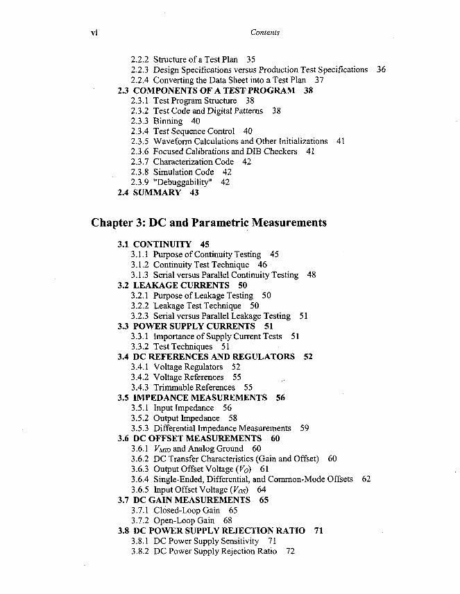
2.2.2 Structure of a Test Plan 352.2.3 Design Specifications versus Production Test Specifications 362.2.4 Converting the Data Sheet into a Test Plan 37
2.3 COMPONENTS OF A TEST PROGRAM 382.3.1 Test Program Structure 382.3.2 Test Code and Digital Patterns 382.3.3 Binning 402.3.4 Test Sequence Control 402.3.5 Waveform Calculations and Other Initializations 412.3.6 Focused Calibrations and DIB Checkers 412.3.7 Characterization Code 422.3.8 Simulation Code 422.3.9 "Debuggability" 42
2.4 SUMMARY 43
Chapter 3: DC and Parametric Measurements
3.1 CONTINUITY 453.1.1 Purpose of Continuity Testing 453.1.2 Continuity Test Technique 463.1.3 Serial versus Parallel Continuity Testing 48
3.2 LEAKAGE CURRENTS 503.2.1 Purpose of Leakage Testing 503.2.2 Leakage Test Technique 503.2.3 Serial versus Parallel Leakage Testing 51
3.3 POWER SUPPLY CURRENTS 513.3.1 Importance of Supply Current Tests 513.3.2 Test Techniques 51
3.4 DC REFERENCES AND REGULATORS 523.4.1 Voltage Regulators 523.4.2 Voltage References 553.4.3 Trimmable References 55
3.5 IMPEDANCE MEASUREMENTS 563.5.1 Input Impedance 563.5.2 Output Impedance 583.5.3 Differential Impedance Measurements 59
3.6 DC OFFSET MEASUREMENTS 603.6.1 VMID and Analog Ground 603.6.2 DC Transfer Characteristics (Gain and Offset) 603.6.3 Output Offset Voltage (Fo) 613.6.4 Single-Ended, Differential, and Common-Mode Offsets 623.6.5 Input Offset Voltage (VOs) 64
3.7 DC GAIN MEASUREMENTS 653.7.1 Closed-Loop Gain 653.7.2 Open-Loop Gain 68
3.8 DC POWER SUPPLY REJECTION RATIO 713.8.1 DC Power Supply Sensitivity 713.8.2 DC Power Supply Rejection Ratio 72
Contents vii
3.9 DC COMMON-MODE REJECTION RATIO 723.9.1 CMRRofOpAmps 723.9.2 CMRR of Differential Gain Stages 75
3.10 COMPARATOR DC TESTS 773.10.1 Input Offset Voltage 773.10.2 Threshold Voltage 783.10.3 Hysteresis 78
3.11 VOLTAGE SEARCH TECHNIQUES 793.11.1 Binary Searches versus Step Searches 793.11.2 Linear Searches 80
3.12 DC TESTS FOR DIGITAL CIRCUITS 823.12.1 Im/IiL 823.12.2 VIHIVIL 823.12.3 VOHIVOL 823.12.4 IOHIIOL' 823.12.5 IOSH and IOSL Short Circuit Current 82
3.13 SUMMARY 83
Chapter 4: Measurement Accuracy
4.1 TERMINOLOGY 874.1.1 Accuracy and Precision 874.1.2 Systematic Errors 884.1.3 Random Errors 884.1.4 Resolution (Quantization Error) 884.1.5 Repeatability 894.1.6 Stability 904.1.7 Correlation 914.1.8 Reproducibility 92
4.2 CALIBRATIONS AND CHECKERS 934.2.1 Traceability to Standards 934.2.2 Hardware Calibration 934.2.3 Software Calibration 934.2.4 System Calibrations and Checkers 964.2.5 Focused Instrument Calibrations 974.2.6 Focused DIB Circuit Calibrations 1014.2.7 DIB Checkers 1024.2.8 Tester Specifications 103
4.3 DEALING WITH MEASUREMENT ERROR 1064.3.1 Filtering 1064.3.2 Averaging 1114.3.3 Guardbanding 113
4.4 BASIC DATA ANALYSIS 1144.4.1 Datalogs 1144.4.2 Histograms 1154.4.3 Noise, Test Time, and Yield 118
4.5 SUMMARY 120
viii Contents
Chapter 5: Tester Hardware
5.1 MIXED-SIGNAL TESTER OVERVIEW 1235.1.1 General-Purpose Testers versus Focused Bench Equipment 1235.1.2 Generic Tester Architecture 123
5.2 DC RESOURCES 1255.2.1 General-Purpose Multimeters 1255.2.2 General-Purpose Voltage/Current Sources 1275.2.3 Precision Voltage References and User Supplies 1285.2.4 Calibration Source 1285.2.5 Relay Matrices 1285.2.6 Relay Control Lines 130
5.3 DIGITAL SUBSYSTEM 1315.3.1 Digital Vectors 1315.3.2 Digital Signals 1315.3.3 Source Memory' 1325.3.4 Capture Memory 1325.3.5 Pin Card Electronics 1345.3.6 Timing and Formatting Electronics 136
5.4 AC SOURCE AND MEASUREMENT 1395.4.1 AC Continuous Wave Source and AC Meter 1395.4.2 Arbitrary Waveform Generators 1395.4.3 Waveform Digitizers 1405.4.4 Clocking and Synchronization 141
5.5 TIME MEASUREMENT SYSTEM 1415.5.1 Time Measurements 1415.5.2 Time Measurement Interconnects 142
5.6 COMPUTING HARDWARE 1435.6.1 User Computer 1435.6.2 Tester Computer 1445.6.3 Array Processors and Distributed Digital Signal Processors 1445.6.4 Network Connectivity 144
5.7 SUMMARY 144
Chapter 6: Sampling Theory
6.1 ANALOG MEASUREMENTS USING DSP 1476.1.1 Traditional versus DSP-Based Testing of AC Parameters 147
6.2 SAMPLING AND RECONSTRUCTION 1486.2.1 Use of Sampling and Reconstruction in Mixed-Signal Testing 1486.2.2 Sampling: Continuous-Time and Discrete-Time Representation 1496.2.3 Reconstruction 1526.2.4 The Sampling Theorem and Aliasing 1596.2.5 Quantization Effects 1616.2.6 Sampling Jitter 166
6.3 REPETITIVE SAMPLE SETS 1706.3.1 Finite and Infinite Sample Sets 1706.3.2 Coherent Signals and Noncoherent Signals 171
Contents ix
6.3.3 Peak-to-RMS Control in Coherent Multitones 1736.3.4 Spectral Bin Selection 175
6.4 SYNCHRONIZATION OF SAMPLING SYSTEMS 1796.4.1 Simultaneous Testing of Multiple Sampling Systems 1796.4.2 ATE Clock Sources 1816.4.3 The Challenge of Synchronization 183
6.5 SUMMARY 184
Chapter 7: DSP-Based Testing
7.1 ADVANTAGES OF DSP-BASED TESTING 1897.1.1 Reduced Test Time 1897.1.2 Separation of Signal Components 1897.1.3 Advanced Signal Manipulations 190
7.2 DIGITAL SIGNAL PROCESSING 1907.2.1 DSP and Array Processing 1907.2.2 Fourier Analysis of Periodic Signals 1917.2.3 The Trigonometric Fourier Series 1927.2.4 The Discrete-Time Fourier Series 1957.2.5 Complete Frequency Spectrum 2057.2.6 Time and Frequency Denormalization 2107.2.7 Complex Form of the DTFS 211
7.3 DISCRETE-TIME TRANSFORMS 2137.3.1 The Discrete Fourier Transform 2137.3.2 The Fast Fourier Transform 2167.3.3 Interpreting the FFT Output 218
7.4 THE INVERSE FFT 2307.4.1 Equivalence of Time-and Frequency-Domain Information 2307.4.2 Parseval's Theorem 2327.4.3 Applications of the Inverse FFT 2337.4.4 Frequency-Domain Filtering 2347.4.5 Noise Weighting 239
7.5 SUMMARY 240APPENDIX A.7.1 241
Chapter 8: Analog Channel Testing
8.1 OVERVIEW 2498.1.1 Types of Analog Channels 2498.1.2 Types of AC Parametric Tests 2508.1.3 Review of Logarithmic Operations 250
8.2 GAIN AND LEVEL TESTS 2518.2.1 Absolute Voltage Levels 2518.2.2 Absolute Gain and Gain Error 2568.2.3 Gain Tracking Error 2588.2.4 PGA Gain Tests 2608.2.5 Frequency Response 265
Contents
8.3 PHASE TESTS 2738.3.1 Phase Response 2738.3.2 Group Delay and Group Delay Distortion 278
8.4 DISTORTION TESTS 2808.4.1 Signal to Harmonic Distortion 2808.4.2 Intel-modulation Distortion 283
8.5 SIGNAL REJECTION TESTS 2848.5.1 Common-Mode Rejection Ratio 2848.5.2 Power Supply Rejection and Power Supply Rejection Ratio 2878.5.3 Channel-to-Channel Crosstalk 2898.5.4 Clock and Data Feedthrough 293
8.6 NOISE TESTS 2938.6.1 Noise 2938.6.2 Idle Channel Noise 2948.6.3 Signal to Noise, Signal to Noise and Distortion 2968.6.4 Spurious Free Dynamic Range 2988.6.5 Weighting Filters 300
8.7 SIMULATION OF ANALOG CHANNEL TESTS 3048.7.1 MATLAB Model of an Analog Channel 304
8.8 SUMMARY 308
Chapter 9: Sampled Channel Testing
9.1 OVERVIEW 3159.1.1 What Are Sampled Channels? 3159.1.2 Examples of Sampled Channels 3159.1.3 Types of Sampled Channels 318
9.2 SAMPLING CONSIDERATIONS 3209.2.1 DUT Sampling Rate Constraints 3209.2.2 Digital Signal Source and Capture 3219.2.3 Simultaneous DAC and ADC Channel Testing 3269.2.4 Mismatched Fundamental Frequencies 3309.2.5 Undersampling 3339.2.6 Reconstruction Effects in AWGs, DACs, and Other Sampled-Data Circuits 335
9.3 ENCODING AND DECODING 3389.3.1 Signal Creation and Analysis 3389.3.2 Data Formats 3399.3.3 Intrinsic Errors 344
9.4 SAMPLED CHANNEL TESTS 3509.4.1 Similarity to Analog Channel Tests 3509.4.2 Absolute Level, Absolute Gain, Gain Error, and Gain Tracking 3519.4.3 Frequency Response 3569.4.4 Phase Response (Absolute Phase Shift) 3599.4.5 Group Delay and Group Delay Distortion 3609.4.6 Signal to Harmonic Distortion, Intennodulation Distortion 3609.4.7 Crosstalk 3619.4.8 CMRR 362
Contents xi
9.4.9 PSRandPSRR 3629.4.10 Signal-to-Noise Ratio and ENOB 3639.4.11 Idle Channel Noise 363
9.5 SUMMARY 364
Chapter 10: Focused Calibrations
10.1 OVERVIEW 36910.1.1 Traceability to National Standards 36910.1.2 Why Are Focused Calibrations Needed? 37010.1.3 Types of Focused Calibrations 37210.1.4 Mechanics of Focused Calibration 37210.1.5 Program Structure 375
10.2 DC CALIBRATIONS 37610.2.1 DC Offset Calibration 37610.2.2 DC Gain and Offset Calibrations 37810.2.3 Cascading DC Offset and Gain Calibrations 380
10.3 AC AMPLITUDE CALIBRATIONS 38210.3.1 Calibrating AWGs and Digitizers 38210.3.2 Low-Level AWG and Digitizer Amplitude Calibrations 38910.3.3 Amplitude Calibrations for ADC and DAC Tests 390
10.4 OTHER AC CALIBRATIONS 39210.4.1 Phase Shifts 39210.4.2 Digitizer and AWG Synchronization 39610.4.3 DAC and ADC Phase Shifts 39610.4.4 Distortion Tests 39610.4.5 Noise Tests 397
10.5 ERROR CANCELLATION TECHNIQUES 39710.5.1 Avoiding Absolute Calibration 39710.5.2 Gain and Phase Matching 39710.5.3 Differential Gain and Differential Phase 399
10.6 SUMMARY 400
Chapter 11: DAC Testing
11.1 BASICS OF CONVERTER TESTING 40311.1.1 Intrinsic Parameters versus Transmission Parameters 40311.1.2 Comparison of DACs and ADCs 40411.1.3 DAC Failure Mechanisms 405
11.2 BASIC DC TESTS 40511.2.1 Code-Specific Parameters 40511.2.2 Full-Scale Range 40611.2.3 DC Gain, Gain Error, Offset, and Offset Error 40611.2.4 LSB Step Size 40911.2.5 DCPSS 410
11.3 TRANSFER CURVE TESTS 41011.3.1 Absolute Error 41011.3.2 Monotonicity 412

xii Contents
11.3.3 Differential Nonlinearity 41211.3.4 Integral Nonlinearity 41611.3.5 Partial Transfer Curves 41911.3.6 Major Carrier Testing 42011.3.7 Other Selected-Code Techniques 423
11.4 DYNAMIC DAC TESTS 42411.4.1 Conversion Time (Settling Time) 42411.4.2 Overshoot and Undershoot 42611.4.3 Rise Time and Fall Time 42611.4.4 DAC-to-DAC Skew 42611.4.5 Glitch Energy (Glitch Impulse) 42711.4.6 Clock and Data Feedthrough 428
11.5 DAC ARCHITECTURES 4281L5.1 Resistive Divider DACs 42811.5.2 Binary-Weighted DACs 43011.5.3 PWMDACs 43111.5.4 Sigma-Delta DACs 43311.5.5 Companded DACs 43411.5.6 Hybrid DAC Architectures 435
11.6 TESTS FOR COMMON DAC APPLICATIONS 43511.6.1 DC References 43511.6.2 Audio Reconstruction 43611.6.3 Data Modulation 43611.6.4 Video Signal Generators 436
11.7 SUMMARY 437APPENDIX A.11.1 437
Chapter 12: ADC Testing
12.1 ADC TESTING VERSUS DAC TESTING 44712.1.1 Comparison of DACs and ADCs 44712.1.2 Statistical Behavior of ADCs 448
12.2 ADC CODE EDGE MEASUREMENTS 45412.2.1 Edge Code Testing versus Center Code Testing 45412.2.2 Step Search and Binary Search Methods 45512.2.3 Servo Method 45512.2.4 Linear Ramp Histogram Method 45612.2.5 Conversion from Histograms to Code Edge Transfer Curves 45712.2.6 Accuracy Limitations of Histogram Testing 46012.2.7 Rising Ramps versus Falling Ramps 46112.2.8 Sinusoidal Histogram Method 462
12.3 DC TESTS AND TRANSFER CURVE TESTS 46712.3.1 DC Gain and Offset 46712.3.2 MLandDNL 46812.3.3 Monotonicity and Missing Codes 469
12.4 DYNAMIC ADC TESTS 47012.4.1 Conversion Time, Recovery Time, and Sampling Frequency 47012.4.2 Aperture Jitter 47212.4.3 Sparkling 472
Contents xiii
12.5 ADC ARCHITECTURES 47312.5.1 Successive Approximation Architectures 47312.5.2 Integrating ADCs (Dual-Slope and Single-Slope) 47412.5.3 Flash ADCs 47512.5.4 Semiflash ADCs 47612.5.5 PDM (Sigma-Delta) ADCs 477
12.6 TESTS FOR COMMON ADC APPLICATIONS 47912.6.1 DC Measurements 47912.6.2 Audio Digitization 47912.6.3 Data Transmission 47912.6.4 Video Digitization 480
12.7 SUMMARY 480
Chapter 13: DIB Design
13.1 DIB BASICS 48313.1.1 Purpose of a Device Interface Board 48313.1.2 DIB Configurations 48413.1.3 Importance of Good DIB Design 486
13.2 PRINTED CIRCUIT BOARDS 48613.2.1 Prototype DIBs versus PCB DIBs 48613.2.2 PCB CAD Tools 48713.2.3 Multilayer PCBs 48813.2.4 PCB Materials 489
13.3 DIB TRACES, SHIELDS, AND GUARDS 49013.3.1 Trace Parasitics 49013.3.2 Trace Resistance 49013.3.3 Trace Inductance 49113.3.4 Trace Capacitance 49613.3.5 Shielding 50213.3.6 Driven Guards 503
13.4 TRANSMISSION LINES 50413.4.1 Lumped-and Distributed-Element Models 50413.4.2 Transmission Line Termination 50813.4.3 Parasitic Lumped Elements 514
13.5 GROUNDING AND POWER DISTRIBUTION 51413.5.1 Grounding 51413.5.2 Power Distribution 51613.5.3 Power and Ground Planes 51713.5.4 Ground Loops 518
13.6 DIB COMPONENTS 51913.6.1 DUT Sockets and Contactor Assemblies 51913.6.2 Contact Pads, Pogo Pins, and Socket Pins 52013.6.3 Electromechanical Relays 52113.6.4 Socket Pins 52413.6.5 Resistors 52513.6.6 Capacitors 52613.6.7 Inductors and Ferrite Beads 52813.6.8 Transformers and Power Splitters 528
Contents
13.7 COMMON DIB CIRCUITS 53013.7.1 Local Relay Connections 53013.7.2 Relay Multiplexers 53213.7.3 Selectable Loads 53313.7.4 Analog Buffers (Voltage Followers) 53313.7.5 Instrumentation Amplifiers 53413.7.6 VMiD Reference Adder 53513.7.7 Current-to-Voltage and Voltage-to-Current Conversions 53613.7.8 Power Supply Ripple Circuits 536
13.8 COMMON DIB MISTAKES 54013.8.1 Poor Power Supply and Ground Layout 54013.8.2 Crosstalk 54113.8.3 Transmission Line Discontinuities 54113.8.4 Resistive Drops in Circuit Traces 54113.8.5 Tester Instrument Parasitics 54113.8.6 Oscillations in Active Circuits 54213.8.7 Poor DIB Component Placement and PCB Layout 542
13.9 SUMMARY 543APPENDIX A.13.1 543
Chapter 14: Design for Test (DfT)14.1 OVERVIEW 549
14.1.1 What Is DfT? 54914.1.2 Built-in Self-Test 55014.1.3 Differences between Digital DfT and Analog DfT 55014.1.4 Why Should We Use DfT? 551
14.2 ADVANTAGES OF DfT 55114.2.1 Lower Cost of Test 55114.2.2 Increased Fault Coverage and Improved Process Control 55314.2.3 Diagnostics and Characterization 55314.2.4 Ease of Test Program Development 55414.2.5 System-Level Diagnostics 55514.2.6 Economics of DfT 555
14.3 DIGITAL SCAN 55614.3.1 Scan Basics 55614.3.2 IEEE Std. 1149.1 Standard Test Access Port and Boundary Scan 55714.3.3 Full Scan and Partial Scan 559
14.4 DIGITAL BIST 56214.4.1 Pseudorandom BILBO Circuits 56214.4.2 Memory BIST 56314.4.3 Microcode BIST 564
14.5 DIGITAL DfT FOR MIXED-SIGNAL CIRCUITS 56514.5.1 Partitioning 56514.5.2 Digital Resets and Presets 56614.5.3 Device-Driven Timing 56714.5.4 Lengthy Preambles 569
14.6 MIXED-SIGNAL BOUNDARY SCAN AND BIST 56914.6.1 Mixed-Signal Boundary Scan (IEEE Std. 1149.4) 569
Contents xv
14.6.2 Analog and Mixed-Signal BIST 57114.7 AD HOC MIXED-SIGNAL DfT 573
14.7.1 Common Concepts 57314.7.2 Accessibility of Analog Signals 57314.7.3 Analog Test Buses, T-Switches, and Bypass Modes 57514.7.4 Separation of Analog and Digital Blocks 57714.7.5 Loopback Modes 57914.7.6 Precharging Circuits and AC Coupling Shorts 58014.7.7 On-Chip Sampling Circuits 58114.7.8 PLL Testability Circuits 58314.7.9 DAC and ADC Converters 58414.7.10 Oscillation BIST 58514.7.11 Physical Test Pads 585
14.8 SUBTLE FORMS OF ANALOG DfT 58514.8.1 Robust Circuits 58514.8.2 Design Margin as DfT 58614.8.3 Avoiding Overspecification 58614.8.4 Predictability of Failure Mechanisms 58614.8.5 Conversion of Analog Functions to Digital 58714.8.6 Reduced Tester Performance Requirements 58714.8.7 Avoidance of Trim Requirements 587
14.9 IDDQ 58714.9.1 Digital IDDQ 58714.9.2 Analog and Mixed-Signal IDDQ 588
14.10 SUMMARY 589APPENDIX A.14.1 589
Chapter 15: Data Analysis
15.1 INTRODUCTION TO DATA ANALYSIS 59715.1.1 The Role of Data Analysis in Test and Product Engineering 59715.1.2 Visualizing Test Results 597
15.2 DATA VISUALIZATION TOOLS 59815.2.1 Datalogs (Data Lists) 59815.2.2 Lot Summaries 59915.2.3 Wafer Maps 60015.2.4 Shmoo Plots 60115.2.5 Histograms 604
15.3 STATISTICAL ANALYSIS 60615.3.1 Mean (Average) and Standard Deviation (Variance) 60615.3.2 Probabilites and Probability Density Functions 60715.3.3 The Standard Gaussian Cumulative Distribution Function <t>(z) 61115.3.4 Non-Gaussian Distributions 61515.3.5 Guardbanding and Gaussian Statistics 61815.3.6 Effects of Measurement Variability on Test Yield 62015.3.7 Effects of Reproducibilty and Process Variation on Yield 623
15.4 STATISTICAL PROCESS CONTROL 62715.4.1 Goals of SPC 62715.4.2 Six-Sigma Quality 628
xvi Contents
15.4.3 Process Capability, Cp, and Cpk 62815.4.4 Gauge Repeatability and Reproducibility 63015.4.5 Pareto Charts 63115.4.6 Scatter Plots 63115.4.7 Control Charts 633
15.5 SUMMARY 634
Chapter 16: Test Economics
16.1 PROFITABILITY FACTORS 64116.1.1 What Is Meant by Test Economics? 64116.1.2 Time to Market 64116.1.3 Testing Costs 64216.1.4 Yield Enhancement 642
16.2 DIRECT TESTING COSTS 64316.2.1 Cost Models 64316.2.2 Cost of Test versus Cost of Tester 64316.2.3 Throughput 645
16.3 DEBUGGING SKILLS 64916.3.1 Sources of Error 64916.3.2 The Scientific Method 64916.3.3 Practical Debugging Skills 65116.3.4 Importance of Bench Instrumentation 65216.3.5 Test Program Structure 65216.3.6 Common Bugs and Techniques to Find Them 653
16.4 EMERGING TRENDS 65516.4.1 Test Language Standards 65516.4.2 Test Simulation 65616.4.3 Noncoherent Sampling 65816.4.4 Built-in Self-Test 65816.4.5 Defect-Oriented Testing 658
16.5 SUMMARY 659
ANSWERS TO SELECTED PROBLEMS 663
INDEX 677