An Introduction to IA-32 Processor Architecture Eddie Lopez CSCI 6303 Oct 6, 2008.
62
An Introduction to IA-32 Processor Architecture Eddie Lopez CSCI 6303 Oct 6, 2008
-
Upload
heather-george -
Category
Documents
-
view
214 -
download
0
Transcript of An Introduction to IA-32 Processor Architecture Eddie Lopez CSCI 6303 Oct 6, 2008.

An Introduction to IA-32 Processor
Architecture
Eddie LopezCSCI 6303
Oct 6, 2008

Overview
Microcomputer Design
Intel IA-32 Family Tree
Operating Environment
Input / Output
The Future
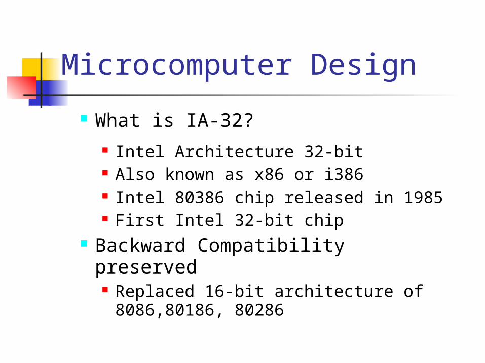
What is IA-32? Intel Architecture 32-bit Also known as x86 or i386 Intel 80386 chip released in 1985 First Intel 32-bit chip
Backward Compatibility preserved Replaced 16-bit architecture of
8086,80186, 80286
Microcomputer Design

Other Manufacturers also produced IA-32 compatible processors
AMD, Cyrix, VIA
Microcomputer Design

Microcomputer Design
The Central Processing Unit (CPU)

Microcomputer Design
Motherboard
Microcomputer Design
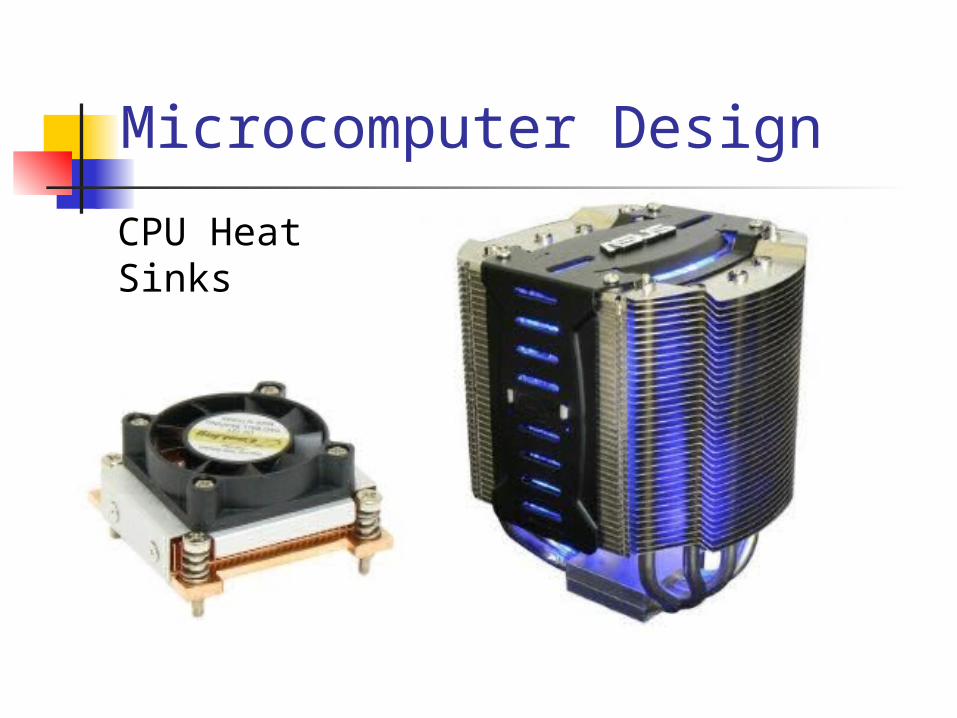
CPU Heat Sinks

Microcomputer Design
The Central Processing Unit contains: Control Unit Arithmetic Logic Unit (ALU) High Frequency Clock Registers

Microcomputer Design

Microcomputer Design
IA-32 Instruction Execution Pipeline: Bus Interface Unit – accesses memory Code Prefetch Unit – instruction queue Instruction Decode Unit – translates to
microcode Execution Unit – executes microcode Segment Unit – translates logical
addresses to linear addresses Paging Unit – translates linear addresses
to physical addresses.

Microcomputer Design
Instruction Execution Cycle Fetch – gets instruction from memory Decode – translate into microcode Fetch input – get data from memory Execute – ALU performs instruction Store output – store data back into
memory

Questions?

IA-32 Architecture
Microcomputer Design
Intel IA-32 Family Tree
Operating Environment
Input / Output
The Future

IA-32 Family Tree
8086 (1979) Segmented Memory 20 bit addressing 1 MB limit

IA-32 Family Tree
80286 (1982) Protected Mode Privilege Rings
Ring 0 – Kernel Ring 1 – OS / Device Drivers Ring 2 – Device Drivers Ring 3 - Applications
IA-32 Family Tree
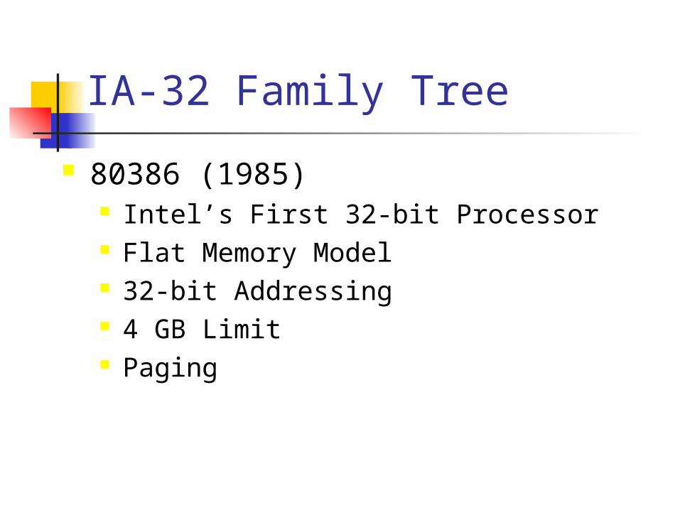
80386 (1985) Intel’s First 32-bit Processor Flat Memory Model 32-bit Addressing 4 GB Limit Paging

IA-32 Family Tree
80486 (1989) Level 1 Cache (8 KB) On-board FPU (Floating Point Unit) 5 Stage Pipeline

IA-32 Family Tree
Pentium (1993) Super Scalar (u,v pipelines) Separate Code and Data Cache (8KB) Branch Prediction

IA-32 Family Tree
Branch Prediction Model
Loop 100 times
Do something
Next loop
Next instruction

IA-32 Family Tree
Pentium Pro (1995) 3 instruction pipelines Out of order execution 36-bit address bus can address 64GB
memory 256kb Level 2 cache MMX Instruction Set
IA-32 Family Tree
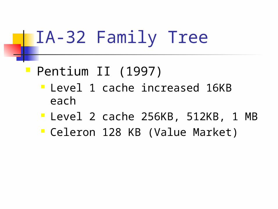
Pentium II (1997) Level 1 cache increased 16KB each Level 2 cache 256KB, 512KB, 1 MB Celeron 128 KB (Value Market)

IA-32 Family Tree
Pentium III (1999) SSE instruction set (XMM registers)
Pentium IV (2000) SSE2 instruction set NetBurst Micro-architecture Hyper-Threading

IA-32 Family Tree
NetBurst Micro-Architecture
•ALU runs at x2 speed
•Dynamic Execution
•Out-Of-Order
IA-32 Family Tree
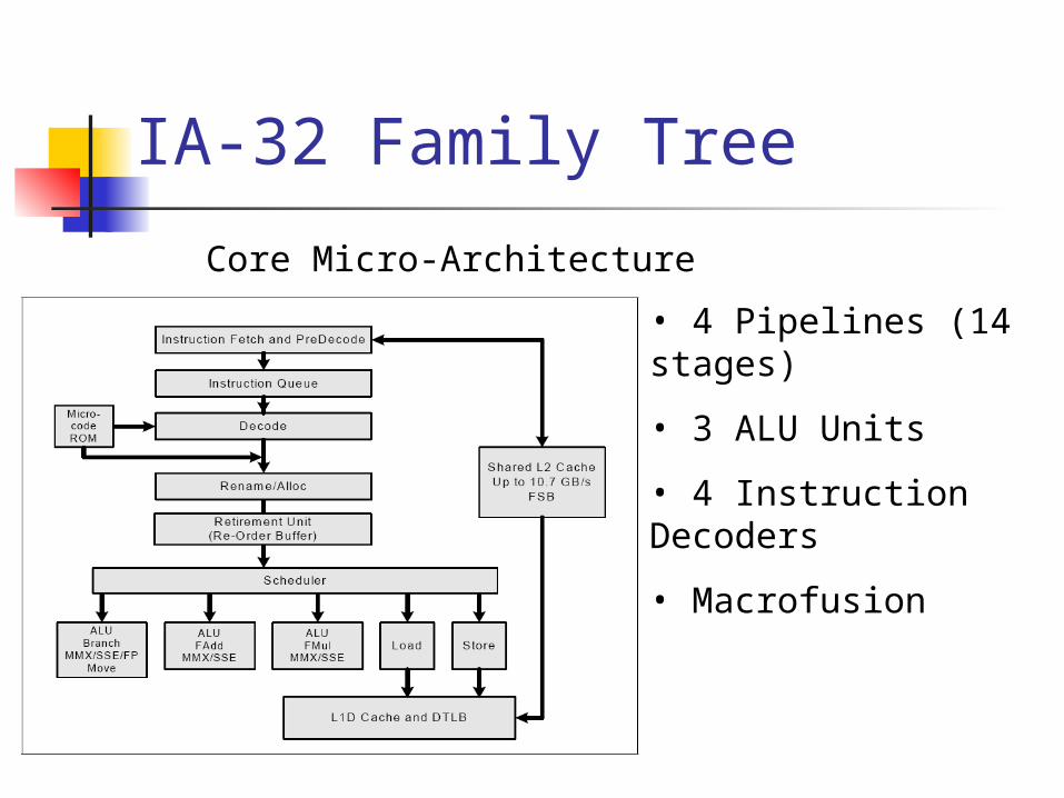
Core Micro-Architecture
• 4 Pipelines (14 stages)
• 3 ALU Units
• 4 Instruction Decoders
• Macrofusion
IA-32 Family Tree
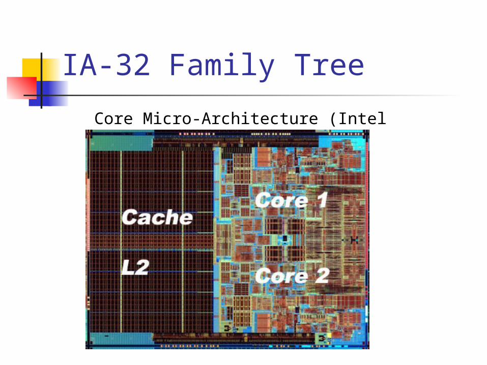
Core Micro-Architecture (Intel Conroe)

Questions?
Overview
Operating Environment Operating Modes
Registers
Memory Management
Instruction Format

Operating Modes
Real Mode Protected Mode System Management Mode Virtual 8086 Mode

Operating Modes
Real Mode Operating mode for 8086 20-bit addressing: 1MB of memory No memory protection or multitasking Modern chips start up in real-mode for
backward compatibility

Operating Modes
Protected Mode Introduced in Intel 80286 chip 32-bit addressing: 4GB of memory Flat memory model Uses privilege rings (0-3) to regulate
applications.

Operating Modes
Protection Rings
Operating Modes
Virtual 8086 Mode Allows “real mode” programs to run
under the supervision of a protected mode operating system
Allows operating systems to run Virtual DOS machines to run legacy software.

Operating Modes
System Management Mode Provides OS with power management
and system security functions.

Registers
What is a register? Storage space on the CPU Used for fast memory storage and
processing Each of the general registers has a
special name and a specific use.

Registers

Registers
Floating Point registers (80-bit) ST0 – ST7 (Part of Floating Point Unit)
MMX registers (64-bit) MMX0 – MMX7
SIMD registers (128-bit) XMM0 – XMM7
Control Registers (32-bit) CR0 - CR4
Registers
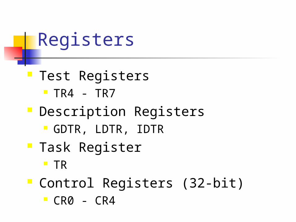
Test Registers TR4 - TR7
Description Registers GDTR, LDTR, IDTR
Task Register TR
Control Registers (32-bit) CR0 - CR4
Registers
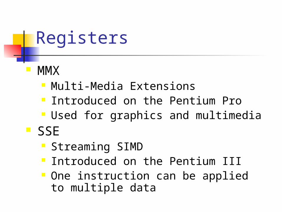
MMX Multi-Media Extensions Introduced on the Pentium Pro Used for graphics and multimedia
SSE Streaming SIMD Introduced on the Pentium III One instruction can be applied to
multiple data

Registers
6 Segment Registers (16 bit) contain address pointers to segments of the currently running process CS Code Segment DS, ES, FS, GS Data Segments SS Stack Segment
1 Instruction Pointer (32-bit) Contains the memory address of the
next instruction to execute.

Registers
Compatibility with previous architecture To allow backward compatibility,
registers EAX, EBX, ECX, and EDX can be addressed as subsets.
Example using the EAX register:

Registers
Roles for Generic Registers EAX – Accumulator EBX – Base Addressing ECX – Counter EDX – Data Operand EDI – Destination Address ESI – Source Address ESP – Stack Pointer EBP – Stack Base Pointer

Registers
EFLAGS register Carry Flag (CF) – Unsigned Carry Overflow Flag (OF) – Signed Overflow Sign Flag (SF) - Negative arithmetic
results Zero Flag (ZF) – Zero arithmetic
results Auxiliary Carry Flag Parity Flag – Even/Odd of a value

Instruction Set
IA-32 Architecture uses CISC CISC – Complex Instruction Set Computer Large amount of complex instructions Easier for compilers and programmers But placed a strain on decoder Backward Compatibility is a burden
RISC Reduced Instruction Set Computer Atomic instructions Easy to decode and run quickly

Instruction Format
Instructions of varying length Design decisions from 8086 have
placed a burden on modern architecture.
One instruction can vary from 1 byte to 17 bytes

Instruction Format
The instruction Format Prefix (0-4 bytes) Opcode (1-3 bytes) R/M Modifier (0-1 byte) SIB Modifier (0-1 byte) Displacement Modifier (0-4 bytes) Data elements (0-4 bytes)

Instruction Format
Prefix (0-4 bytes) Alerts the CPU that address or operand sizes
are about to change Opcode (1-3 bytes)
The operation to execute. Common operations have one byte code, less frequently used ones get three opcodes
R/M Modifier (0-1 byte) Specifies the addressing mode – Register or
Memory

Instruction Format
Scale / Index / Base (0-1 byte) Indicates whether the register serves
as an index or a base and gives the scale factor
Displacement Modifier (0-4 bytes) Provides an additional data offset
Data elements (0-4 bytes) Immediate data (values and
addresses)

Instruction Sets
Types of instructions in the set: Move data between memory and
registers Exchanging data Integer Arithmetic Flow Control Procedure call and return Manipulating the stack Character string operations

Memory Management
Real Mode 20 bit Addressing: 1 MB of memory Addresses: 00000 to FFFFF Memory is logically divided into 64KB
segments Segment registers stored the segment CPU converts segment:offset value to
its linear equivalent

Memory
Reading From Memory Fetching operands from RAM is slow Bus Interface Unit polls RAM for data and
waits. The CPU is goes into a wait state. Requires many clock cycles depending on
speed of RAM. Level-1 cache is much faster – keeps data
near Registers are the fastest

Memory
Reading From Memory Processor places address on the
address bus Processor asserts the memory read
control signal Processor waits for memory to place
the data on the data bus Processor reads the data from the
data bus Processor drops the memory read signal

Memory Management
Protected Mode 32 bit Addressing: 4 GB of memory Addresses: 00000000 to FFFFFFFF Each process “sees” the full 4 GB. Segment registers store indexes to a
global descriptor table. Multiple processes running
simultaneously Prevents processes from corrupting
each other's data.

Memory Management
Paging Segments are divided into 4KB blocks Virtual Memory Manager Blocks are sent to the page file on the
hard disk when they are not in use Switching between applications in low
memory condition requires a delay The more memory, the less paging is
required

Program Execution
What happens when program runs? User clicks on a program icon Operating System (OS) searches for program OS loads programs into available memory
What happens if memory is full? OS Allocates blocks of memory and adjusts
pointers in the code to point to the data OS branches to the first executable instruction At this point, it becomes a Process Memory is released after program ends

Program Execution
Multi-tasking OS can run multiple processes Only one process runs at any given time Processes run in a time slice CPU must support Task Switching Task Switching requires that all registers
and program counter be stored when switching to another process

Questions?

IA-32 Architecture
Microcomputer Design
Intel IA-32 Family Tree
Operating Environment
Input / Output
The Future

Input / Output
Input Keyboard, Mouse, Network Card, etc
Output Monitor, Printer, etc

Input / Output
There are 4 access levels of I/O interaction
Level 3 – High level programming language Level 2 – Operating System API Level 1 – BIOS Level 0 – Direct Hardware interaction
The lower the access level, the faster the result, but what is the trade-off?
Operating System may reserve direct access to hardware

Input / Output
Input/Output is Interrupt Driven What happens when you press a
key on the keyboard? Keyboard sends signal to CPU CPU stops and handles the request by
the keyboard that a key was struck CPU puts keystroke into a buffer and
returns to the previous process

The Future
Intel 64 Shrinking Cores
45 nm core (Intel Penryn) 32 nm (Intel 2009)
Multiple Cores Xeon 7400 Hexcore (9/16/08)
IA-32 phase-out

Questions?
The End…